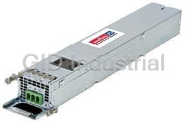
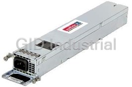
MURATA POWER SOLUTIONS DMR20-4/20S-R-C

Description
DMR20-4/20S-R-C. UNIPOLAR, LOOP-POWERED, RED LED METER. *20% DR DISCOUNT
Part Number
DMR20-4/20S-R-C
Price
Request Quote
Manufacturer
MURATA POWER SOLUTIONS
Lead Time
Request Quote
Category
Circuit Protection » AC-DC Power Supply
Specifications
Manufacturer
Murata Power Solutions
Manufacturers Part #
DMR20-4/20S-R-C
Industry Aliases
Factory Pack Quantity
12
Datasheet
Extracted Text
DMR20-4/20 Series Loop-Powered, 4-20 mA LED Display Process Monitors with 2.5V Loop Drop FEATURES Murata’s new DMR20-4/20 loop-powered digital process monitors feature a large, 2.5V maximum loop-drop (125 Ω burden) for red LED model! easy-to-read, bright LED display. All operating power is derived directly from the High-quality, 20-turn, span (gain) and zero (offset) Self-powered directly from 4-20 mA current loop, no external current loop itself—no external power source is required! The large, 0.30 [7.6 mm] power source needed digits exhibit uniform intensity over the entire 4-20 mA operating range. Unlike other Fits round 1.20 inch [30.5 mm] cutouts; less than 1.00 inch loop-powered LED displays, the total maximum loop voltage drop for the red LED [<25.4 mm] behind-the-panel depth model is 2.5V! Users no longer have to settle for difficult-to-read LCD displays in Ea sy-to-read, 0.30 inch [7.6 mm] high LED digits with excellent loop-powered applications. dis play brightness; available in red or green LEDs Both gain (span) and offset (zero) adjustments are performed with on-board, Supplied with EPDM rubber gasket and hex nut pr ecision, 20-turn potentiometers. All decimal-point and range-change selections are made on a six-position DIP switch featuring vibration-resistant, gold-plated High-quality, 20-turn, span (gain) and zero (offset) adjustments contacts. Unlike competitive meters, there are no jumpers or solder gaps to open Gold-plated DIP-switch for range and decimal points: Reliable sc rew-terminal input connections or close. Connections to the current loop are made via a reliable, two-position, screw-type terminal block. Rugged, polycarbonate, one-piece package The DMR20-4/20’s DIP-switch and potentiometers accommodate hundreds of Protected against dust and water submersion to IP67/NEMA 6 different input-current/output-reading combinations. This versatility eliminates the need to order more costly, long-lead-time customs meters in applications in which several different-range meters are required. The round plastic housing fits standard 1.20” [30.5mm] panel cutouts. An EPDM rubber gasket and hex nut simplify installation and provide IP67/NEMA 6 protection to environmental dirt and moisture. SIMPLIFIED SCHEMATIC DIAGRAM For full details go to: http://www.murata-ps.com/en/support/rohs- compliance.html www.murata-ps.com/support MPM_DMR20-4/20.A01 Page 1 of 5 DMR20-4/20 Series Subminiature 4-20 mA Loop-Powered 3½ Digit LED Process Monitors Performance/Functional Specifications OPERATING AND SETUP INSTRUCTIONS Typical at TA = +25°C, unless otherwise noted. DMR20-4/20S (Unipolar Reading Model) Current Loop Input Min. Typ. Max. Units As shipped, the DMR20-4/20S is factory calibrated to read “000” for a Full Scale Input Range ➀ +4 – +20 mA 4 mA input and “1000” for a 20 mA input. The following worst-case procedure assumes the DMR20-4/20S is completely misadjusted, i.e., – 175 Ω Input Impedance ➁ both potentiometers and the DIP switches are randomly set .When Loop Voltage Drop - Red LED ➁ – 2.2 2.5 Volts performing DIP-switch settings, be sure the DIP switch’s small Loop Voltage Drop - Green LED 3.2 3.5 Volts actuators are firmly engaged in their fully-ON or fully-OFF positions. ➁ Overcurrent Protection ➀ – – ±40 mA 1. Set R7 (full scale span/gain adjust) and R3 (zero/offset adjust) fully Performance counterclockwise, roughly 22 turns, and set SW1-SW6 to OFF. Sampling Rate 2.5 readings per second 2. Select DIP switch setting #2 in Table 1. Accuracy (1 minute warm-up) ±0.05% FS ±2 Count 3. Apply a precision 4 mA input to TB1 with proper polarity, and adjust Temperature Drift (0 to +60°C) – ±0.15 ±0.3 Cnts/°C R3 until the meter’s display reads “000.” Display 4. Apply a precision 20 mA input and adjust R7 until the meter’s display Display Type and Size 3½ digit, 0.30” / 7.6 mm high red LED reads “1000.” Repeat steps 3 and 4 to make sure the adjustments Polarity Indication “–” for negative reading do not affect one another. Overrange Indication “–1 “ for negative Vin 5. If required, select the appropriate decimal point by setting SW1 and “1 “ for positive Vin SW2 per the settings shown in Table 3. Physical/Environmental NOTE: If a display reading other than ”000” to ”1000” is Operating Temperature 0 – +60 °C desired, refer to DIP–Switch Settings Table 1 below for SW3– SW6 settings. Storage Temperature –40 – +75 °C Humidity (non-condensing) Table 1 0 – 85 % Case Material Polycarbonate DMR20-4/20S (Unipolar Model) DIP-Switch Settings Weight 0.65 ounces (18.5 grams) Display Readings ➀ The DMR20-4/20, using any of the DIP-switch settings described above, can 4 mA 20 mA SW3 SW4 SW5 SW6 withstand overcurrents, including those resulting from accidental reverse-polarity 1 000 to 1200-1999 Off Off Off Off connections, up to ±40 mA without sustaining any damage. 2 000 to 750-1350 On Off Off Off ➁ Because DMR20-4/20 loop-powered meters employ active circuitry to convert the loop current into a voltage; the meters’ effective series impedance varies in a 3 000 to 500-850 Off On Off Off manner that maintains the loop voltage drop relatively constant over the full 4-to- 4 000 to 350-600 Off Off On Off 20 mA current range. Listed input impedance specification applies at 20 mA with all DIP switches set to OFF. 5 000 to 250-350 On On On Off ➂ When looking up DIP-switch settings in the following Tables and the desired 6 000 to 150-250 On Off On On display readings can be achieved with either of two different settings, using the higher setting # will produce less sensitive offset (R3) and span (R7) Examples (DMR20-4/20S-Unipolar Models) adjustments. Please keep in mind that the accuracy specification of ±2 counts means it may not always be possible to obtain the exact desired display 1. Desired display readings are: reading. 4 mA = “0.00” Ordering Information 20 mA = “6.00” DMR20-4/20S-R-C Unipolar, loop-powered red LED meter Use DIP-switch setting #3 in Table 1 and enable decimal point DP2 by DMR20-4/20S-G-C Unipolar, loop-powered green ED meter setting SW1 to ‘On’ and SW2 to ‘Off’. Apply 4 mA and adjust R3 so DMR20-4/20B-R-C Unipolar, loop-powered red LED meter the display reads “0.00.” Apply 20 mA and adjust R7 so the display reads “6.00.” Note: An M30 x 1.5 nylon metric hex nut and EPDM sealing 2. Desired display readings are: gasket are supplied with each meter. The “-C” suffix indicates 4 mA=“000” RoHS compliance 20 mA =“800” Panel Knockout Tools: Use DIP-switch setting #2 in Table 1. Apply 4 mA and adjust R3 so DMR20-1-KP 1.22” [30.9 mm] punch (no keying notch) the display reads “000.” Apply 20 mA and adjust R7 so the display DMR20-2-KP 1.21” [30.7 mm] punch with 4 keying notches reads “800.” For these display readings, no decimal points are used DMR20-3-KP Keyway Punch tool so set SW1 and SW2 both to On. www.murata-ps.com/support MPM_DMR20-4/20.A01 Page 2 of 5 DMR20-4/20 Series Subminiature 4-20 mA Loop-Powered 3½ Digit LED Process Monitors 3. Desired display readings are: Examples (DMR20-4/20B-Bipolar Model) 4 mA =.”000” 12 mA =.”250” 1. Desired display readings are: This example is not as straightforward as the previous two. Notice that 4 mA=“–1.00” 12 mA is exactly halfway between 4 mA and 20 mA. If we assume that 20 mA =“1.00” the input could go up to 20 mA, the display reading would then be: 2 Use DIP-switch setting #5 in Table 2 and enable decimal point DP2 by x. 250 or .”500.” From Table 1 we can now select DIP-switch setting setting SW1 to ‘On’ and SW2 to ‘Off’. Apply 12 mA and adjust R3 so #4 and enable DP1 by setting SW1 to Off and SW2 to On. Apply 4 mA the display reads “0.00.” Apply 20 mA and adjust R7 so the display and adjust R3 so the display reads ”000.” Apply 12 mA and adjust R7 reads “1.00.” Apply 4 mA and verify that the display reads “–1.00,” so the display reads ”250.” readjust R3 and R7 if necessary. DMR20–4/20B (Bipolar Reading Model) 2. Desired display readings are: 4 mA=“–450” The DMR20-4/20B’s zero-offset circuit differs from the unipolar ‘S’ model described above in that with the ‘B’ model, a half-scale 12 mA input is 20 mA =“450” normally set to display ”000.” Therefore, all of the DIP-switch settings in Use DIP-switch setting #2 in Table 2. Apply 12 mA and adjust R3 so Table 2 assume a reading of “000” is desired with a 12 mA input. the display reads “000.” Apply 20 mA and adjust R7 so the display When configuring the DMR20-4/20B for the first time, or when selecting a reads “450.” Apply 4 mA and verify that the display reads “–450.” Repeat adjustment procedure if necessary. For these display new range, set both R3 and R7 fully counterclockwise (roughly 22 turns) readings, no decimal points are used, so set SW1 and SW2 to On. to their minimum offset/minimum-span positions, respectively. Then select the desired readings from Table 2 and configure DIP-switches 3. Desired display readings are: SW3, SW4, SW5, and SW6 accordingly. 4 mA=“–650” The procedure below illustrates how to calibrate the DMR20-4/20B to its 20 mA =“650” factory-calibrated readings of “–1000” with a 4 mA input and “1000” with Select DIP-setting # 1 in Table 2. Apply 12 mA and adjust R3 so the a 20 mA input. When performing DIP-switch settings, be sure the DIP- display reads “000.” Apply 20 mA and adjust R7 so the display reads switch’s small actuators are firmly engaged in their fully-ON or fully-OFF “650.” Apply 4 mA and verify that the display reads “–650.” Repeat positions. adjustment procedure if necessary. For these display readings, no 1. Set both R3 and R7 fully counterclockwise. decimal points are used, so set SW1 and SW2 to On. 2. Select DIP-switch setting #1 from Table 2. Table 3 3. Apply a precision 12 mA input and adjust R3 until the meter’s Decimal Point Settings (All Models) display reads “000.” 4. Apply a precision 20 mA input and adjust R7 until the meter’s SW1 SW2 Decimal Point display reads “1000.” Off Off DP3 5. Apply a precision 4 mA input and the display should read “–1000.” Repeat steps 3 and 4 to make sure the two adjustments did not affect On Off DP2 one another. Off On DP1 On On None Table 2 DMR20-4/20B (Bipolar Model) DIP-Switch Settings 4 mA 12 mA 20 mA SW3 SW4 SW5 SW6 1 –600 to –1000 000 600 to 1000 Off Off Off Off 2 –400 to –600 000 400 to 600 On Off Off Off 3 –250 to –400 000 250 to 400 Off On Off Off 4 –150 to –250 000 150 to 250 Off Off On Off 5 –100 to –150 000 100 to 150 On Off On On 6 –70 to –100 000 70 to 100 Off On On On www.murata-ps.com/support MPM_DMR20-4/20.A01 Page 3 of 5 DMR20-4/20 Series Subminiature 4-20 mA Loop-Powered 3½ Digit LED Process Monitors CONNECTION DIAGRAM Figure 2 Typical DMR20-4/20 Connection Diagram INSTALLATION DIAGRAM Figure 3 Panel Installation www.murata-ps.com/support MPM_DMR20-4/20.A01 Page 4 of 5 DMR20-4/20 Series Subminiature 4-20 mA Loop-Powered 3½ Digit LED Process Monitors MECHANICAL SPECIFICATIONS AND RECOMMENDED PANEL CUTOUT http://www.murata-ps.com/en/3d/meters.html Recommended Terminations at TB1 Available Panel Knockout Tools WIRE SIZE: 18 to 26 AWG (Solid or stranded) DMR20-1-KP 1.22” [30.9 mm] punch (no keying notch) STRIPPING LENGTH: 0.20” [5.1 mm] Nominal DMR20-2-KP 1.21” [30.7 mm] punch with 4 keying notches DMR20-3-KP Keyway Punch tool This product is subject to the following operating requirements Murata Power Solutions, Inc. and the Life and Safety Critical Application Sales Policy: 11 Cabot Boulevard, Mansfield, MA 02048-1151 U.S.A. Refer to: http://www.murata-ps.com/requirements/ ISO 9001 and 14001 REGISTERED Murata Power Solutions, Inc. makes no representation that the use of its products in the circuits described herein, or the use of other technical information contained herein, will not infringe upon existing or future patent rights. The descriptions contained herein do not imply the granting of licenses to make, use, or sell equipment constructed in accordance therewith. Specifications are subject to change without notice. © 2015 Murata Power Solutions, Inc. www.murata-ps.com/support MPM_DMR20-4/20.A01 Page 5 of 5
Frequently asked questions
How does Electronics Finder differ from its competitors?

Is there a warranty for the DMR20-4/20S-R-C?

Which carrier will Electronics Finder use to ship my parts?

Can I buy parts from Electronics Finder if I am outside the USA?

Which payment methods does Electronics Finder accept?

Why buy from GID?

Quality
We are industry veterans who take pride in our work

Protection
Avoid the dangers of risky trading in the gray market

Access
Our network of suppliers is ready and at your disposal

Savings
Maintain legacy systems to prevent costly downtime

Speed
Time is of the essence, and we are respectful of yours


 Manufacturers


What they say about us
FANTASTIC RESOURCE
One of our top priorities is maintaining our business with precision, and we are constantly looking for affiliates that can help us achieve our goal. With the aid of GID Industrial, our obsolete product management has never been more efficient. They have been a great resource to our company, and have quickly become a go-to supplier on our list!
Bucher Emhart Glass
EXCELLENT SERVICE
With our strict fundamentals and high expectations, we were surprised when we came across GID Industrial and their competitive pricing. When we approached them with our issue, they were incredibly confident in being able to provide us with a seamless solution at the best price for us. GID Industrial quickly understood our needs and provided us with excellent service, as well as fully tested product to ensure what we received would be the right fit for our company.
Fuji
HARD TO FIND A BETTER PROVIDER
Our company provides services to aid in the manufacture of technological products, such as semiconductors and flat panel displays, and often searching for distributors of obsolete product we require can waste time and money. Finding GID Industrial proved to be a great asset to our company, with cost effective solutions and superior knowledge on all of their materials, it’d be hard to find a better provider of obsolete or hard to find products.
Applied Materials
CONSISTENTLY DELIVERS QUALITY SOLUTIONS
Over the years, the equipment used in our company becomes discontinued, but they’re still of great use to us and our customers. Once these products are no longer available through the manufacturer, finding a reliable, quick supplier is a necessity, and luckily for us, GID Industrial has provided the most trustworthy, quality solutions to our obsolete component needs.
Nidec Vamco
TERRIFIC RESOURCE
This company has been a terrific help to us (I work for Trican Well Service) in sourcing the Micron Ram Memory we needed for our Siemens computers. Great service! And great pricing! I know when the product is shipping and when it will arrive, all the way through the ordering process.
Trican Well Service
GO TO SOURCE
When I can't find an obsolete part, I first call GID and they'll come up with my parts every time. Great customer service and follow up as well. Scott emails me from time to time to touch base and see if we're having trouble finding something.....which is often with our 25 yr old equipment.
ConAgra Foods