

 Manufacturers
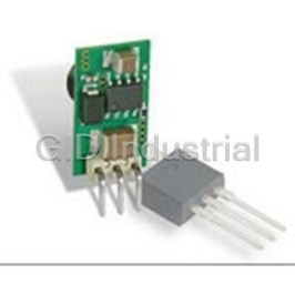
MURATA POWER SOLUTIONS LSM2-T/30-D12R-C

Description
Module DC-DC 12VIN 1-OUT 0.8V to 5V 30A 125W 10-Pin Case C-71
LSM2-T/30-D12R-C
Part Number
LSM2-T/30-D12R-C
Price
Request Quote
Manufacturer
MURATA POWER SOLUTIONS
Lead Time
Request Quote
Category
Capacitors » DC-DC Converter
Specifications
Manufacturer
Murata Power Solutions
Manufacturers Part #
LSM2-T/30-D12R-C
Lead Time
14 Week Lead Time
Series
LSM2-T/30-D12
Factory Pack Quantity
250
Cooling Method
Convection
Dimensions
1.30 x 0.53 x 0.36"
Efficiency
94%
Input Voltage Nominal
12 VDC
Mechanical Style
Non-Isolated / POL
Mounting
SMD/SMT
Operating Temperature
- 40 to + 85°C
Output Amps 1
30 A
Power
125 W
Subcategory
DC-DC Converter
Datasheet

Extracted Text
LSM2-T/30-D12 Series www.murata-ps.com DOSA-SMT, 30A POL DC/DC Converters Typical unit FEATURES DESCRIPTION Non-isolated Point-of-Load (POL) converter, ideal Today’s high performance CPU and programma- no additional external components required, for mixed voltage systems ble logic devices demand superior performance stable no-load operation, up to 10,000 µF output Optimized for CPUs, DSPs and programmable logic from their power source. The LSM2-T/30-D12 load capacitance and no reverse conduction. - FPGAs, ASICs series DC/DC converters offer up to 30 Amps System functions offer a remote On/Off 30 Amps maximum output current continuous output power with a user-selectable control, two additional ground pins (optional) output of 0.8 to 3.6 Volts. 25 Amps output is and a load Sense input. These converters meet User-selectable output voltage, 0.8Vdc to 5.0Vdc via trim resistor or voltage input available up to 5.0 Vout. This tiny converter is agency standards UL/EN 60950-1, CAN/CSA- ideal for applications with an input range of C22.2 60950-1, IEC 60950-1, 2nd edition, and Wide input range 6Vdc to 14Vdc (Vout <3.6V) 6 to 14 Volts DC. The pinout, trim system and EN55022/CISPR22 emissions characterization. Selectable phased start-up sequencing and tracking mechanical footprint is compatible with the DOSA The automated surface mount assembly is fully Excellent efficiency over output voltage range (www.dosapower.com) industry standard. compatible with RoHS (Reduction of Hazard- Two models available, with or without additional To ensure very high performance of powered ous Substances) construction and attachment. ground/thermal pads logic systems, the LSM2-T/30-D12 features low The LSM2-T/30-D12 mounts to its host carrier Fast settling, high di/dt slew rate, low output noise output noise, high slew rates (20 Amps/µSec.), board via reflow-soldered PCB pads. fast transient response (25 µSec settling) and The extraordinary efficiency means low heat Extensive self protection plus 'hiccup' short circuit tight line and load regulation. Many logic devices and freedom from expensive, bulky heat sinks. A auto recovery require controlled start up and tracking capabili- wealth of protection features include input under- Meets full safety and emission certification ties. The LSM2-T/30-D12 includes a Sequence/ voltage shutdown, output overcurrent current lim- Track function and prebias protection against iting, short circuit protection and overtemperature external startup voltages. Other features include shutdown/recycle. For full details go to www.murata-ps.com/rohs www.murata-ps.com/support MDC_LSM2_T30_D12 Series.E03∆ Page 1 of 12 LSM2-T/30-D12 Series DOSA-SMT, 30A POL DC/DC Converters PERFORMANCE SPECIFICATIONS SUMMARY AND ORDERING GUIDE Output Input Package R/N (mVp-p) Regulation (max.) Efficiency VOUT IOUT Power VIN Nom. Range IIN (Case/ Model Family (Volts) (Amps) (Watts) Typ. Max. Line Load (Volts) (Volts) (mA/A) Min. Typ. Pinout) LSM2-T/30-D12-C 0.8-5 30 125 15 25 ±0.2% ±0.4% 12 6-14 210/11.1 92.5% 94% C71, P72 LSM2-T/30-D12R-C To Be 0.8-5 30 125 15 25 ±0.2% ±0.4% 12 6-14 210/11.1 92.5% 94% C71, P72 LSM2-T/30-D12R-C-CIS 0.8-5 30 125 15 25 ±0.2% ±0.4% 12 6-14 210/11.1 92.5% 94% C71, P72 Typical @ Ta=+25°C. under nominal line voltage and full-load conditions unless noted. Nominal Nominal line voltage, no-load/full-load conditions. output is +5 Volts. LSM2-T/30-D12 efficiencies are shown at Vout = 5 Volts. Ripple/Noise (R/N) is tested/specified over a 5 Hz to 20 MHz bandwidth and may be reduced by Iout max. is 30 Amps with Vout = 0.8 to 3.6 Volts. With Vout >3.6 Volts, Iout max. is 25 Amps. adding external filtering. R/N is shown at Vout <= 2.5 Volts. ➆ If Vout >3.63V, input range is 7-14V. These devices have no minimum load requirements and will regulate under no-load conditions. ➇ LSM2-T/30-D12R-C-CIS models use a 100KΩ resistor between the gate and source of the internal Regulation specifications describe the output voltage deviation as the line voltage or load is varied On/Off (Enable) FET controlling the PWM. from its nominal/midpoint value to either extreme. PART NUMBER STRUCTURE L SM2 - T / 30 - D12 R - C RoHS6 Hazardous Substance Compliant Output Configuration: (does not claim EU RoHS exemption 7b–lead in solder) L = Unipolar Low Voltage Additional Grounds: Blank = Omitted R = Installed Non-Isolated SMT Nominal Output Voltage: Input Voltage Range: 0.8-5.0 Volts D12 = 6-14 Volts (12V nominal) See note 7 above. Maximum Rated Output Current in Amps CONNECTION DIAGRAM +OUTPUT +INPUT Additional +SENSE ground/thermal * pads COMMON COMMON VCC CURRENT PWM SENSE ON/OFF CONTROLLER CONTROL REFERENCE & VTRACK/ VOUT ERROR AMP SEQUENCE TRIM INPUT Typical topology is shown. *One phase of two is shown. www.murata-ps.com/support MDC_LSM2_T30_D12 Series.E03∆ Page 2 of 12 LSM2-T/30-D12 Series DOSA-SMT, 30A POL DC/DC Converters MECHANICAL SPECIFICATIONS Case C71 PIN #1 THIS SMT contacts: copper alloy with CORNER (FARSIDE) 5μ" Au (min.) over 50μ" Ni (min.) INPUT/OUTPUT CONNECTIONS P72 13.5 TOP 0.53 VIEW Pad Function 1 On/Off Control 2 +Input ISOMETRIC VIEW 33.0 3 Sequence/Track In 1.30 PIN #1 4 Common SIDE END 5 +Output VIEW VIEW 6 Trim 9.1 0.36 7 Sense In 9* Common MTG PLANE 10* Common 0.020 MIN 2.03±0.13 BETWEEN MTG PLANE Pins 9 & 10 PRESENT 0.080±0.005 * AND COMPONENTS 1.57±0.20 REF ONLY ON 'R' OPTION 0.062±0.008 CONTACTS TYP ALL PINS COPLANAR WITHIN 4 MILS 4 EQ SP @ 8.76 0.190 [4.83] EACH Dimensions are in inches (mm) shown for ref. only. 0.345 EQUALS 0.760 [19.30] Third Angle Projection 4.83 Component locations 0.190 BOTTOM are typical. REF VIEW 3 4 5 6 7 3.05 0.120 Tolerances (unless otherwise specified): 10.92 .XX ± 0.02 (0.5) 9 1.91 0.430 10 .XXX ± 0.010 (0.25) 0.075 Angles ± 2˚ 2 1 Components are shown for reference only. 1.27 29.90 0.050 1.177 2.90 0.69 1.22 0.114 0.027 0.048 1.47 2.16 0.058 0.085 0.64 DIMENSIONS ARE IN INCHES [mm] 0.025 1 2 0 0 TOLERANCES: 10 2 PLACE 0.02 ANGLES: 1 9 2.26 3 PLACE 0.010 3.05 14.0 0.089 2.41 * 0.120 0.55 0.095 COMPONENTS SHOWN ARE FOR REFERENCE ONLY 3 4 5 6 7 10.29 REF 0.405 MATERIAL: SMT PINS: COPPER ALLOY 3.56 2.41 0.095 [2.41] x 0.140 [3.56] x FINISH: (ALL PINS) 0.140 0.095 0.082 [2.08] PADS GOLD (5u"MIN) OVER NICKEL (50u" MIN) 0.095 [2.41] REF REF FOR PINS 9 & 10 PADS FOR PINS (OPTIONAL GNDS) 1 THRU 7 (7 PLS) 33.5 1.32 Additional Ground/Thermal Pads (“R” models) To realize the additional current and thermal capacity of “R” models, you must have a substantial area of several square inches of copper etch flow- The LSM2-T/30-D12 is optionally available with two additional ground soldered to these pads and sufficient feed-throughs or other means of con- pads for increased current handling and better heat transfer. These are ducting current. The “R” pads and the standard pads 1 and 2 are in parallel. indicated with the “R” designator in the model number, LSM2-T/30-D12R-C. MPS recommends that users lay out their PC boards to accept these two If your application uses a standard DOSA pad layout and you cannot connect pads for larger current applications. Please note that the Derating curves for to these ground pads, order model LSM2-T/30-D12-C without the “R” designa- the “R” models accept higher temperature and greater current limits than tor. Please observe the lower Derating curves for standard, “non-R” models. units without the additional pads. www.murata-ps.com/support MDC_LSM2_T30_D12 Series.E03∆ Page 3 of 12 30.58 1.204 29.90 1.177 26.85 1.057 22.02 0.867 17.20 0.677 12.37 0.487 7.54 0.297 0 LSM2-T/30-D12 Series DOSA-SMT, 30A POL DC/DC Converters SHIPPING SPECIFICATIONS FEED (UNWIND) PICK-UP NOZZLE LOCATION DIRECTION ------ ( 6mm MAX) PIN #1 TYP (ORIENTATION) 2.0 4.00 9.7 0.08 0.157 0.38 TYP 20.3 40.4 44.0 0.80 35.1 1.59 1.73 1.38 REF WIDTH 24.00 0.945 PITCH Dimensions are in inches (mm) shown for ref. only. Third Angle Projection TOP COVER TAPE Tolerances (unless otherwise specified): .XX ± 0.02 (0.5) .XXX ± 0.010 (0.25) Angles ± 2˚ Components are shown for reference only. PIN #1 FEED (UNWIND) THIS CORNER (FAR SIDE) DIRECTION 44.0 ------- 1.73 REF 16.5 PICKUP NOZZLE 0.65 LOCATION ( 6.5-7.5mm) 330.2 13.00 101.6 13.00 4.00 0.512 (CORE) 6.7 0.27 REEL INFORMATION PICK & PLACE PICKUP (P/U) (250 UNITS PER REEL) www.murata-ps.com/support MDC_LSM2_T30_D12 Series.E03∆ Page 4 of 12 LSM2-T/30-D12 Series DOSA-SMT, 30A POL DC/DC Converters Performance and Functional Specifications See Note 1 Input Dynamic Characteristics Input Voltage Range See Ordering Guide Dynamic Load Response 60 µSec to within ±2% of final value (50-100-50% load step, di/dt=20A/µSec) Isolation Not isolated. Input and output Commons are internally connected. Start-Up Time 10 mSec for Vout=nominal (Vin on to Vout regulated or On/Off to Vout) Start-Up Voltage 5.6 Volts Switching Frequency 430 KHz Undervoltage Shutdown 5 Volts Overvoltage Shutdown None Environmental Reflected (Back) Ripple Current (Note 2) 50 mA pk-pk Calculated MTBF (4) 3,917,077 Hours Internal Input Filter Type Capacitive Operating Temperature Range -40 to +85°C. (Note 9) With derating See Derating Curves (Note 12) Reverse Polarity Protection None, install external fuse. Storage Temperature Range -55 to +125°C. Recommended External Fuse 35 Amps, fast blow Thermal Protection/Shutdown +115°Celsius Input Current: Full Load Conditions See Ordering Guide MSL Rating 2a 2 Inrush Transient 0.4 A Sec. Relative Humidity to 85%/+85°C, non-condensing Shutdown Mode (Off, UV, OT) 5 mA Output Short Circuit 60 mA Physical Low Line (Vin=Vmin, 5Vout) 18.9 Amps Outline Dimensions See Mechanical Specifications Remote On/Off Control (Note 5) Weight 0.28 ounces (7.8 grams) Negative Logic (No model suffix) ON = Open pin or 0 to +0.55 V max. Electromagnetic Interference Meets EN55022/CISPR22 OFF = +3.0V min. to +Vin max. (conducted and radiated) (may need external filter) Current 1.3 mA max. Safety Meets UL/cUL 60950-1, IEC/EN 60950-1, Output 2nd edition Minimum Loading No minimum load Absolute Maximum Ratings Accuracy (50% load) ±1.5 % of Vnominal Input Voltage (Continuous or transient) +15 Volts Voltage Adjustment Range (Note 13) See Ordering Guide On/Off Control (negative logic) Zero Volts min. to +Vin max. Overvoltage Protection (Note 20) None Input Reverse Polarity Protection None, install external fuse. ο Temperature Coefficient ±0.01% per C of Vout range Output Current (Note 7) Current-limited. Devices can withstand Ripple/Noise (20 MHz bandwidth) See Ordering Guide and Note 8 sustained short circuit without damage. Line/Load Regulation (See Tech. Notes) See Ordering Guide and Note 10 ° Storage Temperature -55 to +125 C. Efficiency See Ordering Guide Lead Temperature See soldering guidelines Maximum Capacitive Loading (Note 15) Cap-ESR=0.001 to 0.01 Ohms 5,000 µF Absolute maximums are stress ratings. Exposure of devices to greater than any of these conditions may adversely affect long-term reliability. Proper operation under conditions other than those listed Cap-ESR >0.01 Ohms 10,000 µF in the Performance/Functional Specifications Table is neither implied nor recommended. Current Limit Inception (Note 19) 48 Amps (cold startup) Specification Notes: (98% of Vout setting) 42 Amps (after warm up) (1) Specifications are typical at +25°C, Vin=nominal (+12V), Vout=nominal (+5V), full load, external Short Circuit Mode (Note 6) caps and natural convection unless otherwise indicated. Tests at full power should supply substantial forced airflow. Short Circuit Current Output 600 mA All models are tested and specified with external 0.1µF and 10 µF paralleled ceramic/tantalum Protection Method Hiccup autorecovery upon overload output capacitors and a 22 µF external input capacitor. All capacitors are low ESR types. These removal. (Note 17) capacitors are necessary to accommodate our test equipment and may not be required to achieve specified performance in your applications. All models are stable and regulate within spec under Short Circuit Duration Continuous, no damage (output shorted no-load conditions. to ground) (2) Input Back Ripple Current is tested and specified over a 5 Hz to 20 MHz bandwidth. Input filter- ing is Cin=2 x 100 µF tantalum, Cbus=1000 µF electrolytic, Lbus=1 µH. Prebias Startup (Note 16) Converter will start up if the external (3) Note that Maximum Power Derating curves indicate an average current at nominal input output voltage is less than Vnominal. voltage. At higher temperatures and/or lower airflow, the DC/DC converter will tolerate brief full Sequencing current outputs if the total RMS current over time does not exceed the Derating curve. (4) Mean Time Before Failure is calculated using the Telcordia (Belcore) SR-332 Method 1, Case 3, Slew Rate 2V per millisecond max. ground fixed conditions, Tpcboard=+25°C, full output load, natural air convection. Startup delay until sequence start 10 milliseconds min. (5) The On/Off Control may be driven with external logic or by applying appropriate external volt- ages which are referenced to -Input Common. The On/Off Control Input should use either an Tracking accuracy, rising input Vout=±100 mV of Sequence In open collector/open drain transistor or logic gate which does not exceed +Vin. Tracking accuracy, falling input Vout=±200 mV of Sequence In (6) Short circuit shutdown begins when the output voltage degrades approximately 2% from the selected setting. Remote Sense to Vout 0.5V max. (Note 7) www.murata-ps.com/support MDC_LSM2_T30_D12 Series.E03∆ Page 5 of 12 LSM2-T/30-D12 Series DOSA-SMT, 30A POL DC/DC Converters Specification Notes continued: Resistor Trim Equation (7) If Sense is connected remotely at the load, up to 0.5 Volts difference is allowed between the Sense and +Vout pins to compensate for ohmic voltage drop in the power lines. A larger volt- age drop may cause the converter to exceed maximum power dissipation. 1200 (8) Output noise may be further reduced by adding an external filter. See I/O Filtering and Noise Reduc- RTRIM (in Ohms) = --------------------- -100 tion. VOUT – 0.8 (9) All models are fully operational and meet published specifications, including “cold start” at –40°C. (10) Regulation specifications describe the deviation as the line input voltage or output load current is varied from a nominal midpoint value to either extreme. The fixed trim resistors to set the output voltage are: (11) Other input or output voltage ranges will be reviewed under scheduled quantity special order. (12) Maximum continuous power requires that all on-board components not exceed +128°C pack- Vout 0.8V. 1.0V. 1.2V. 1.5V. 1.8V. age temperature. 1.614 (13) Do not exceed maximum power specifications when adjusting the output trim. Rtrim (Ohms) Open 5.90 KΩ 2.90 KΩ 1.10 KΩ KΩ (14) The “R” option includes extra ground pads. These pads offer two important features. In addition to carrying extra current, they also help dissipate additional heat. MPS strongly recommends Vout 2.0V. 2.5V. 3.3V. 5.0V. soldering the “R” pads to a thick ground plane with sizable area. The Operating Temperature 185.71 specification listed above assumes that these additional ground pads are connected to Rtrim (Ohms) 0.90 KΩ 605 Ω 380 Ω Ω a substantial ground plane below the converter ( at least several square inches). (15) The maximum output capacitive loads depend on the the Equivalent Series Resistance (ESR) of the external output capacitor. Larger caps will reduce output noise but may slow transient response. (16) Do not use Pre-bias startup and sequencing together. If you do not use the track function, leave the seq/trk pin open. (17) After short circuit shutdown, if the load is partially removed such that the load still exceeds the overcurrent (OC) detection, the converter will remain in hiccup restart mode. (18) Output current limiting is disabled at start up to avoid overcurrent shutdown while charging external bypass capacitors. Voltage Reference, Output Adjustments The LSM2-T/30-D12 series includes a special output voltage trimming fea- ture which is fully compatible with competitive units. The output voltage may be varied using a single trim resistor from the Trim Input to Power Common. ο Use a precision, low-tempco resistor (±100 ppm/ C) mounted close to Figure 2. Voltage Trim Connections the converter with short leads. Be aware that the voltage accuracy is ±1.5% (typical) therefore adjust this resistance to achieve your desired output. Voltage Trim The LSM2 Series may also be trimmed using an external low-noise voltage applied between the Trim input and Output Common. Be aware that the inter- nal “load” impedance looking into Trim pin is below 1000 Ohms and includes factors from the output voltage. Therefore, use a low impedance source resistance in your external voltage reference. The fixed trim voltages to set the output voltage are: Vout (typ.) 0.80V. 1.0V. 1.2V. 1.5V. 1.8V. Vtrim (Volts) Open 0.731V. 0.719V. 0.7V. 0.682V Figure 1. Trim Resistor Connections Vout (typ.) 2.0 V. 2.5V. 3.3V. 5.0V. Vtrim (Volts) 0.669V. 0.638V. 0.589V. 0.484V. Vtrim = 0.7434 – [(((Vout – 0.7434) ÷ 1620) – 0.000035) x 100] where Vout = desired voltage Soldering Guidelines Murata Power Solutions recommends the specifications below when installing these converters. These specifications vary depending on the solder type. Exceeding these specifica- tions may cause damage to the product. Your production environment may differ therefore please thoroughly review these guidelines with your process engineers. Reflow Solder Operations for surface-mount products (SMT) For Sn/Ag/Cu based solders: For Sn/Pb based solders: Preheat Temperature Less than 1 ºC. per second Preheat Temperature Less than 1 ºC. per second Time over Liquidus 45 to 75 seconds Time over Liquidus 60 to 75 seconds Maximum Peak Temperature 260 ºC. Maximum Peak Temperature 235 ºC. Cooling Rate Less than 3 ºC. per second Cooling Rate Less than 3 ºC. per second www.murata-ps.com/support MDC_LSM2_T30_D12 Series.E03∆ Page 6 of 12 LSM2-T/30-D12 Series DOSA-SMT, 30A POL DC/DC Converters PERFORMANCE DATA: OUTPUT VOLTAGE = 5 VOLTS Efficiency vs. Line Voltage and Load Current @ +25°C Output Ripple & Noise (Vin = 12 V, Iout = 20 A, Cout = 10µF || 1µF, ’scope = 20 MHz BW) Vertical = 20 mV/div., Sweep = 1µS/div. 98 93 88 VIN = 14 V 83 VIN = 12 V VIN = 7 V 78 73 68 63 58 1 2.66 4.31 5.97 7.62 9.28 10.9 12.6 14.2 15.9 17.6 19.2 20.9 22.5 24.2 Load Current (Amps) LSM2-T/30-D12R Maximum Current Temperature Derating at Sea Level Power-On Startup (Vin = 12 V, Iout = 25 A) (Vin= 12V, Transverse Airflow). Extra ground pads installed. Ch2 = 20 A/div. 31.00 30.00 300 LFM 29.00 400 LFM 28.00 500 LFM 27.00 26.00 25.00 24.00 23.00 22.00 21.00 20.00 Natural Convection 19.00 100 LFM 18.00 200 LFM 17.00 16.00 15.00 14.00 13.00 12.00 20 25 30 35 40 45 50 55 60 65 70 75 80 85 90 Ambient Temperature (°C) LSM2-T/30-D12 Maximum Current Temperature Derating at Sea Level StepLoad Transient Response (Vin = 12 V, 0-15A-0) (Vin= 12V, Transverse Airflow). No extra ground pads. 31.00 30.00 29.00 28.00 300 LFM 27.00 400 LFM 26.00 500 LFM 25.00 24.00 23.00 22.00 21.00 20.00 19.00 18.00 17.00 16.00 Natural Convection 15.00 100 LFM 14.00 200 LFM 13.00 12.00 11.00 20 25 30 35 40 45 50 55 60 65 70 75 80 85 90 Ambient Temperature (°C) www.murata-ps.com/support MDC_LSM2_T30_D12 Series.E03∆ Page 7 of 12 Output Current (Amps) Output Current (Amps) Efficiency (%) LSM2-T/30-D12 Series DOSA-SMT, 30A POL DC/DC Converters PERFORMANCE DATA: OUTPUT VOLTAGE = 3.3 VOLTS Efficiency vs. Line Voltage and Load Current (Vin = 12V) @ +25°C Output Ripple & Noise (Vin = 12 V, Iout = 20 A, Cout = 10µF || 1µF, ’scope = 20 MHz BW) Vertical = 20 mV/div., Sweep = 1µS/div. 93 88 VIN = 14 V 83 VIN = 12 V VIN = 6 V 78 73 68 63 58 1 2 3 4 5 6 7 8 9 10 11 12 13 14 15 16 17 18 19 20 21 22 23 24 25 26 27 28 29 30 O utput Current (Amps) LSM2-T/30-D12R Maximum Current Temperature Derating at Sea Level Power-On Startup (Vin = 12 V, Iout = 25 A) (Vin= 12V, Transverse Airflow). Extra ground pads installed. 31.00 30.00 300 LFM 29.00 400 LFM 28.00 27.00 26.00 25.00 24.00 23.00 22.00 21.00 20.00 Natural Convection 100 LFM 19.00 200 LFM 18.00 17.00 16.00 15.00 14.00 13.00 12.00 20 25 30 35 40 45 50 55 60 65 70 75 80 85 90 Ambient Temperature (°C) LSM2-T/30-D12 Maximum Current Temperature Derating at Sea Level StepLoad Transient Response (Vin = 12 V, 0-15A-0) (Vin= 12V, Transverse Airflow). No extra ground pads. 31.00 30.00 400 LFM 29.00 500 LFM 28.00 27.00 26.00 25.00 24.00 23.00 22.00 21.00 20.00 Natural Convection 19.00 100 LFM 18.00 200 LFM 17.00 300 LFM 16.00 15.00 14.00 13.00 12.00 20 25 30 35 40 45 50 55 60 65 70 75 80 85 90 Ambient Temperature (°C) www.murata-ps.com/support MDC_LSM2_T30_D12 Series.E03∆ Page 8 of 12 Output Current (Amps) Output Current (Amps) Efficiency (%) LSM2-T/30-D12 Series DOSA-SMT, 30A POL DC/DC Converters PERFORMANCE DATA: OUTPUT VOLTAGE = 2.5 VOLTS Efficiency vs. Line Voltage and Load Current (Vin = 12V) @ +25°C Output Ripple & Noise (Vin = 12 V, Iout = 20 A, Cout = 10µF || 1µF, ’scope = 20 MHz BW) Vertical = 20 mV/div., Sweep = 1µS/div. 93 88 VIN = 14 V 83 VIN = 12 V VIN = 6 V 78 73 68 63 58 1 2 3 4 5 6 7 8 9 10 11 12 13 14 15 16 17 18 19 20 21 22 23 24 25 26 27 28 29 30 O utput Current (Amps) LSM2-T/30-D12R Maximum Current Temperature Derating at Sea Level (Vin= 12V, Transverse Airflow). Extra ground pads installed. 31.00 30.00 300 LFM 29.00 400 LFM 28.00 27.00 26.00 25.00 24.00 23.00 22.00 Natural Convection 21.00 100 LFM 20.00 200 LFM 19.00 18.00 17.00 16.00 15.00 20 25 30 35 40 45 50 55 60 65 70 75 80 85 90 Ambient Temperature (°C) LSM2-T/30-D12 Maximum Current Temperature Derating at Sea Level StepLoad Transient Response (Vin = 12 V, 0-15A-0) (Vin= 12V, Transverse Airflow). No extra ground pads. 31.00 30.00 29.00 28.00 27.00 300 LFM 26.00 400 LFM 25.00 24.00 23.00 22.00 21.00 20.00 19.00 Natural Convection 18.00 100 LFM 17.00 200 LFM 16.00 15.00 14.00 13.00 20 25 30 35 40 45 50 55 60 65 70 75 80 85 90 Ambient Temperature (°C) www.murata-ps.com/support MDC_LSM2_T30_D12 Series.E03∆ Page 9 of 12 Output Current (Amps) Output Current (Amps) Efficiency (%) LSM2-T/30-D12 Series DOSA-SMT, 30A POL DC/DC Converters PERFORMANCE DATA: OUTPUT VOLTAGE = 1.8 VOLTS Efficiency vs. Line Voltage and Load Current @ +25°C Output Ripple & Noise (Vin = 12 V, Iout = 20 A, Cout = 10µF || 1µF, ’scope = 20 MHz BW) Vertical = 10 mV/div., Sweep = 1µS/div. 91 86 81 VIN = 14 V 76 VIN = 12 V VIN = 6 V 71 66 61 56 1 2 3 4 5 6 7 8 9 10 11 12 13 14 15 16 17 18 19 20 21 22 23 24 25 26 27 28 29 30 Load Current (Amps) LSM2-T/30-D12R Maximum Current Temperature Derating at Sea Level Power-On Startup (Vin = 12 V, Iout = 25 A) (Vin= 12V, Transverse Airflow). Extra ground pads installed. 31.00 30.00 300 LFM 29.00 400 LFM 28.00 27.00 26.00 25.00 Natural Convection 24.00 100 LFM 200 LFM 23.00 22.00 21.00 20.00 19.00 18.00 17.00 20 25 30 35 40 45 50 55 60 65 70 75 80 85 90 Ambient Temperature (°C) LSM2-T/30-D12 Maximum Current Temperature Derating at Sea Level StepLoad Transient Response (Vin = 12 V, 0-15A-0) (Vin= 12V, Transverse Airflow). No extra ground pads. 31.00 30.00 300 LFM 29.00 400 LFM 28.00 27.00 26.00 25.00 24.00 23.00 22.00 21.00 20.00 Natural Convection 19.00 100 LFM 18.00 200 LFM 17.00 16.00 15.00 14.00 13.00 20 25 30 35 40 45 50 55 60 65 70 75 80 85 90 Ambient Temperature (°C) www.murata-ps.com/support MDC_LSM2_T30_D12 Series.E03∆ Page 10 of 12 Output Current (Amps) Output Current (Amps) Efficiency (%) LSM2-T/30-D12 Series DOSA-SMT, 30A POL DC/DC Converters PERFORMANCE DATA: OUTPUT VOLTAGE = 1.2 VOLTS Efficiency vs. Line Voltage and Load Current @ +25°C (Vin = 12V) Output Ripple & Noise (Vin = 12 V, Iout = 30 A, Cout = 10µF || 1µF, ’scope BW = 20 MHz) 89 84 79 VIN = 6 V VIN = 12 V VIN = 14 V 74 69 64 59 54 49 1 2 3 4 5 6 7 8 9 10 11 12 13 14 15 16 17 18 19 20 21 22 23 24 25 26 27 28 29 30 Output Current (Amps) LSM2-T/30-D12R Maximum Current Temperature Derating Power-On Startup (Vin = 12 V, Iout = 30 A) (Vin= 12V, Transverse Airflow). Extra ground pads installed. 31.00 300 LFM 30.00 400 LFM 29.00 28.00 27.00 26.00 25.00 24.00 23.00 22.00 Natural Convection 21.00 100 LFM 200 LFM 20.00 19.00 18.00 17.00 16.00 20 25 30 35 40 45 50 55 60 65 70 75 80 85 90 Ambient Temperature (°C) StepLoad Transient Response (Vin = 12 V, 0-15A-0) www.murata-ps.com/support MDC_LSM2_T30_D12 Series.E03∆ Page 11 of 12 Efficiency (%) Output Current (Amps) LSM2-T/30-D12 Series DOSA-SMT, 30A POL DC/DC Converters PERFORMANCE DATA: OUTPUT VOLTAGE = 0.8 VOLTS Efficiency vs. Line Voltage and Load Current @ +25°C (Vin = 12V) Output Ripple & Noise (Vin = 12 V, Iout = 30 A, Cout = 10µF || 1µF, ’scope BW = 20 MHz) 87 82 77 VIN = 14 V 72 VIN = 12 V VIN = 6 V 67 62 57 52 47 42 1 2 3 4 5 6 7 8 9 10 11 12 13 14 15 16 17 18 19 20 21 22 23 24 25 26 27 28 29 30 Output Current (Amps) LSM2-T/30-D12R Maximum Current Temperature Derating Power-On Startup (Vin = 12 V, Iout = 30 A) (Vin= 12V, Transverse Airflow). Extra ground pads installed. 31.00 300 LFM 30.00 29.00 400 LFM 28.00 27.00 26.00 25.00 24.00 23.00 Natural Convection 22.00 100 LFM 21.00 200 LFM 20.00 19.00 18.00 17.00 16.00 20 25 30 35 40 45 50 55 60 65 70 75 80 85 90 Ambient Temperature (°C) StepLoad Transient Response (Vin = 12 V, 0-15A-0) This product is subject to the following operating requirements Murata Power Solutions, Inc. and the Life and Safety Critical Application Sales Policy: 129 Flanders Road, Westborough, MA 01581 U.S.A. Refer to: http://www.murata-ps.com/requirements/ ISO 9001 and 14001 REGISTERED Murata Power Solutions, Inc. makes no representation that the use of its products in the circuits described herein, or the use of other technical information contained herein, will not infringe upon existing or future patent rights. The descriptions contained herein do not imply the granting of licenses to make, use, or sell equipment constructed in accordance therewith. Specifications are subject to change without notice. © 2018 Murata Power Solutions, Inc. www.murata-ps.com/support MDC_LSM2_T30_D12 Series.E03∆ Page 12 of 12 Efficiency (%) Output Current (Amps)
Frequently asked questions
How does Electronics Finder differ from its competitors?

Is there a warranty for the LSM2-T/30-D12R-C?
Which carrier will Electronics Finder use to ship my parts?
Can I buy parts from Electronics Finder if I am outside the USA?
Which payment methods does Electronics Finder accept?
Why buy from GID?

Quality
We are industry veterans who take pride in our work

Protection
Avoid the dangers of risky trading in the gray market

Access
Our network of suppliers is ready and at your disposal

Savings
Maintain legacy systems to prevent costly downtime

Speed
Time is of the essence, and we are respectful of yours
Related Products
DC/DC 8-36VIN/3.3VOUT .5A SIP 7803SR-C
DC/DC 8-36VIN/3.3VOUT .5A HSIP 7803SRH-C
DC/DC 8-36VIN/5VOUT .5A SIP 7805SR-C
DC/DC 8-36VIN/5VOUT .5A HSIP 7805SRH-C
4.8 W, 15 -36 VDC VIN, SINGLE OUTPUT, 12 VDC@0.4 A DC-DC CONVERTER 7812SR-C
4.8 W, 15 -36 VDC VIN, SINGLE OUTPUT, 12 VDC@0.4 A DC-DC CONVERTER 7812SRH-C
Request a Quote

The quote request has been received
Close

Facing challenges or have inquiries? Feel free to contact us!
Call Us +1-469-283-2440
What they say about us
FANTASTIC RESOURCE
One of our top priorities is maintaining our business with precision, and we are constantly looking for affiliates that can help us achieve our goal. With the aid of GID Industrial, our obsolete product management has never been more efficient. They have been a great resource to our company, and have quickly become a go-to supplier on our list!
Bucher Emhart Glass
EXCELLENT SERVICE
With our strict fundamentals and high expectations, we were surprised when we came across GID Industrial and their competitive pricing. When we approached them with our issue, they were incredibly confident in being able to provide us with a seamless solution at the best price for us. GID Industrial quickly understood our needs and provided us with excellent service, as well as fully tested product to ensure what we received would be the right fit for our company.
Fuji
HARD TO FIND A BETTER PROVIDER
Our company provides services to aid in the manufacture of technological products, such as semiconductors and flat panel displays, and often searching for distributors of obsolete product we require can waste time and money. Finding GID Industrial proved to be a great asset to our company, with cost effective solutions and superior knowledge on all of their materials, it’d be hard to find a better provider of obsolete or hard to find products.
Applied Materials
CONSISTENTLY DELIVERS QUALITY SOLUTIONS
Over the years, the equipment used in our company becomes discontinued, but they’re still of great use to us and our customers. Once these products are no longer available through the manufacturer, finding a reliable, quick supplier is a necessity, and luckily for us, GID Industrial has provided the most trustworthy, quality solutions to our obsolete component needs.
Nidec Vamco
TERRIFIC RESOURCE
This company has been a terrific help to us (I work for Trican Well Service) in sourcing the Micron Ram Memory we needed for our Siemens computers. Great service! And great pricing! I know when the product is shipping and when it will arrive, all the way through the ordering process.
Trican Well Service
GO TO SOURCE
When I can't find an obsolete part, I first call GID and they'll come up with my parts every time. Great customer service and follow up as well. Scott emails me from time to time to touch base and see if we're having trouble finding something.....which is often with our 25 yr old equipment.
ConAgra Foods