

 Manufacturers
MURATA POWER SOLUTIONS LSS-T/10-W12-C

Description
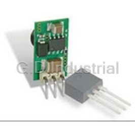
Module DC-DC 12VIN 1-OUT 0.591V to 6V 10A 60W 5-Pin SIP
LSS-T/10-W12-C
Part Number
LSS-T/10-W12-C
Price
Request Quote
Manufacturer
MURATA POWER SOLUTIONS
Lead Time
Request Quote
Category
Capacitors » DC-DC Converter
Specifications
Manufacturer
Murata Power Solutions
Manufacturers Part #
LSS-T/10-W12-C
Lead Time
14 Week Lead Time
Industry Aliases
LSS-T/10-W12C
Selling Alternatives
OKR-T/10-W12-C
Series
LSS-T/10-W12
Factory Pack Quantity
360
Cooling Method
Convection
Dimensions
0.65 x 0.41 x 0.38"
Efficiency
93%
Input Voltage Nominal
12 VDC
Mechanical Style
Non-Isolated / POL
Mounting
Through Hole
Operating Temperature
- 40 to + 85°C
Output Amps 1
10 A
Power
60 W
Subcategory
DC-DC Converter
Datasheet

Extracted Text
LSS-T/10-W12 www.murata-ps.com Adjustable Output 10 Amp SIP-mount DC/DC Converter PRODUCT OVERVIEW Fabricated on a Single Inline Package (SIP) module, stable no-load operation. A key feature is select- the LSS-T/10-W12 series is a miniature non-iso- able output voltage either by precision resistor, lated Point-of-Load (POL) switching DC/DC power trim pot or user’s voltage input. The output range is converter for embedded applications. The converter adjustable from 0.6 to 6 Vdc. offers both tight regulation and high efficiency A wealth of protection features prevents damage directly at the power usage site. Typically, no extra to both the converter and outside circuits. Inputs outside components are required. The module are protected from undervoltage and outputs offer mounts vertically, occupying a tiny board footprint. short circuit protection, overcurrent and excess The upright mounting improves cooling airflow. temperature shut down. The unit is designed to Suggested applications include powering CPU’s, meet all EMI/RFI certifications as well as HALT distributed bus architectures (DBA) with a master reliability. RoHS6 hazardous material compliance bus power supply, programmable logic and mixed is specified as standard. All units are precision voltage systems. assembled in a highly automated computer- FEATURES Based on synchronous buck converter topology, controlled surface mount facility with ISO-traceable the extraordinary efficiency means very low heat manufacturing quality standards. Additional system n Vertical SIP-mount small footprint package and little electrical noise. The ultra wide input functions include a remote On/Off control. n Output from 0.6 to 6 Volts up to range is 4.5 to 13.8 Volts. Additional features 51 Watts include quick transient response to step loads and n Ultra-wide 4.5 to 13.8 Vdc input range n Outstanding thermal performance and derating n Extensive self-protection and short circuit features with no output reverse conduction n On/Off control and trim functions n High efficiency up to 93% with no heatsink n Fully protected against temperature and voltage limits n Designed to meet UL/IEC/EN60950-1 safety approvals Simplified Block Diagram +VIN +VOUT PWM On/Off Controller Control OT Common Common Signal Conditioning Trim Typical topology is shown. Figure 1. LSS-T/10-W12 Series, 10 Amp Model For full details go to www.murata-ps.com/rohs www.murata-ps.com/support MDC_MDC_LSS-T10-W12.C01 Page 1 of 8 LSS-T/10-W12 Adjustable Output 10 Amp SIP-mount DC/DC Converter ➁ Performance Specifications and Ordering Guide ORDERING GUIDE Output Input Package Iout R/N (mVp-p)➁ Regulation (Max.)➂ Iin, Iin, Efficiency Vout (Amps Power Vin Nom. Range no load full load Root Model ➁ (Volts) max) (Watts) Typ. Max. Line Load (Volts) (Volts) (mA) (Amps) Min. Typ. Case C72 ➀ Pinout 0.41 × 0.65 × 0.4 LSS-T/10-W12 0.591 – 6 10 60 45 75 ±0.2% ±1.4% 12 4.5 – 13.8 80 4.48 91.5 93 (10.4 × 16.5 × 10.2) P73 I/O caps are necessary for our test equipment and may not be needed for your application. ➀ Dimensions are in inches (mm). ➁ All specifications are at nominal line voltage, Vout = 5V and full load, +25 °C unless otherwise ➂ Vin must be 2V or higher than Vout for 3.3 to 5V outputs. noted. See detailed specifications. Output capacitors are 2 x 0.47 µF ceramic. Input cap is 22 µF. PART NUMBER STRUCTURE L SS - T / 10 - W12 - C Output Configuration: RoHS Hazardous L = Unipolar Substance Compliance Low Voltage C = RoHS6 (does not claim EU RoHS exemption Non-Isolated SIP 7b–lead in solder) Output Voltage Range Wide Input Voltage Range T = Trimmable, 0.6 – 6 Volts W12 = 4.5 – 13.8 Volts (10Amp) Maximum Rated Output Current in Amps MECHANICAL SPECIFICATIONS 0.41 0.38 MAX (10.4) (9.7) INPUT/OUTPUT CONNECTIONS LSS-T/10-W12 0.24 MAX 0.205 REF Pin Function P73 (6.1) (5.2) 1 Enable On/Off 2 +Vin 3 Ground 4 +Vout 0.65 5 Output Trim (16.5) 0.12 (3.0) Dimensions are in inches (mm) shown for ref. only. 0.06 REF THK Third Angle Projection (1.5) 0.067 (1.7) 0.05 0.067 (1.7) (1.3) .032 (0.8) ±.002 OR 0.134 (3.4) Tolerances (unless otherwise specified): .025 (0.6) ±.002 TYP .XX ± 0.02 (0.5) 0.134 (3.4) .XXX ± 0.010 (0.25) Angles ± 2˚ Components are shown for reference only. Figure 2 . LSS-T/10-W12 Series Component locations are typical. www.murata-ps.com/support MDC_MDC_LSS-T10-W12.C01 Page 2 of 8 LSS-T/10-W12 Adjustable Output 10 Amp SIP-mount DC/DC Converter Performance/Functional Specifications Dynamic Characteristics All specifications are typical unless noted See Note 1. Dynamic Load Response 20 µSec to within ±2% of final value Input (0 to 50% load step, di/dt = 10A/µSec, no external caps) Input Voltage Range See Ordering Guide. See note 19. Turn-On Time 6 mSec for Vout regulated Recommended External Fuse 20 Amps Remote On/Off Time 6 mSec for Vout regulated Isolation Not isolated. The input and output Switching Frequency 600 kHz commons internally connected. Start-up Voltage 4.2 Volts Environmental Undervoltage Shutdown 3.4 Volts Calculated MTBF (Note 4) TBC Overvoltage Shutdown None Operating Temperature Range –45 to +85°C (Note 9) Reflected (Back) Ripple Current 20 mA pk-pk With Derating See Derating Curves (Note 18) Internal Input Filter Type Capacitive Storage Temperature Range –55 to +125°C Reverse Polarity Protection1(Note 15) See fuse information Thermal Protection Shutdown +115°C Input Current: Relative Humidity 85%/+85°C Full Load Conditions See Ordering Guide 2 Inrush Transient 0.4 A sec Physical Shutdown mode (Off, UV, OT) 5 mA Output Short-Circuit 60 mA Outline Dimensions See Mechanical Specifications No load, 5Vout 80 mA Weight 0.07 ounces (2 grams) Low Line (Vin = Vmin, 5Vout) 11.95 Amps Electromagnetic Interference Designed to meet FCC Part 15, EN55022, Remote On/Off Control (Note 5) (may require external filter) conducted and radiated (LSS-T/10-W12, no suffix) Safety Designed to meet UL/cUL 60950-1, CSA-C22.2 Positive Logic On = +1.5 V to plus Vin max. or open pin Off = 0 to +0.2 V max. or ground pin No. 60950-1, IEC/EN 60950-1 Current 1 mA Absolute Maximum Ratings Output Input Voltage Minimum Loading (Note 7) No minimum load Continuous or transient 15 Volts max. Maximum Output Power 51 Watts (Note 11) Output Power 51 Watts max. Accuracy (50% load) ±1.5% of V setting On/Off Control 0V. min to +Vin max. Voltage Adjustment Range (Notes 13, 19) See Ordering Guide Input Reverse-Polarity Protection See Fuse section Temperature Coefficient ±0.02% max. per °C of Vout range Output Current Current limited. Devices can withstand sustained Ripple/Noise (20MHz bandwidth) See Ordering Guide and Note 8 output short circuits without damage. Line Load Regulation (See Tech Notes) See Ordering Guide and Note 10 Storage Temperature –40 to +125°C Efficiency See Ordering Guide Lead Temperature See soldering guidelines Maximum Capacitive Loading Cap-ESR = 0.001 to 0.01 Ω 5,000 µF Absolute maximums are stress ratings. Exposure of devices to greater than any of these Cap-ESR > 0.01 Ω 10,000 µF conditions may adversely affect long-term reliability. Proper operation under conditions other than those listed in the Performance/Functional Specifications Table is not implied Current Limit Inception (98% of Vout setting) (Note 12) nor recommended. 33 Amps (after warm up) Short Circuit Mode (Note 6, 12) CAUTION: This product is not internally fused. To comply with safety agency certifications Short Circuit Current Output 0.6 Amp and to avoid injury to personnel or equipment, the user must supply an external fast-blow Protection Method Hiccup autorecovery upon overload fuse to the input terminals. See fuse information. removal. (Note 16) Short Circuit Duration Continuous, no damage (output shorted to ground) www.murata-ps.com/support MDC_MDC_LSS-T10-W12.C01 Page 3 of 8 LSS-T/10-W12 Adjustable Output 10 Amp SIP-mount DC/DC Converter Notes (1) All models are tested and specified with external 1||10 μF ceramic/tantalum output (9) All models are fully operational and meet published specifications, including “cold start” at capacitors and a 22 μF external input capacitor. All capacitors are low ESR types. These –40°C. capacitors are necessary to accommodate our test equipment and may not be required (10) Regulation specifications describe the deviation as the line input voltage or output load to achieve specified performance in your applications. All models are stable and regulate current is varied from a nominal midpoint value to either extreme. within spec under no-load conditions. (11) For the LSS-T/10-W12, the maximum rated output power is 51 Watts (5.1 Volts and All specifications are typical unless noted. General conditions for Specifications are 10 Amps). Output adjustment up to 6 Volts must reduce current to remain within the +25 °C, Vin=nominal, Vout=5V, full load. Adequate airflow must be supplied for extended 51 Watt output limit. testing under power. (12) Output current limit and short circuit protection is non-latching. When the overcurrent (2) Input Ripple Current is tested and specified over a 5 Hz to 20 MHz bandwidth. Input filter- fault is removed, the converter will immediately recover. ing is Cin=2 × 100 μF, 100V tantalum, Cbus=1000 μF, 100V electrolytic, Lbus=1 μH. (13) Do not exceed maximum power specifications when adjusting the output trim. (3) Note that Maximum Power Derating curves indicate an average current at nominal input (14) At zero output current, the output may contain low frequency components which exceed voltage. At higher temperatures and/or lower airflow, the DC/DC converter will tolerate the ripple specification. The output may be operated indefinitely with no load. brief full current outputs if the total RMS current over time does not exceed the Derating curve. All Derating curves are presented at sea level altitude. Be aware of reduced power (15) Input Fusing: If reverse polarity is accidentally applied to the input, a body diode will dissipation with increasing density altitude. become forward biased and will conduct considerable current. To ensure reverse input protection with full output load, always connect an external input fast-blow fuse in series (4) Mean Time Before Failure is calculated using the Telcordia (Belcore) SR-332 Method 1, with the +Vin input. Use approximately twice the full input current rating with nominal Case 3, ground fixed conditions, Tpcboard=+25°C, full output load, natural air convec- input voltage. tion. (16) “Hiccup” overcurrent operation repeatedly attempts to restart the converter with a brief, (5) The On/Off Control is normally controlled by a switch or open collector or open drain tran- full-current output. If the overcurrent condition still exists, the restart current will be sistor. But it may also be driven with external logic or by applying appropriate external removed and then tried again. This short current pulse prevents overheating and damag- voltages which are referenced to Input Common. ing the converter. Once the fault is removed, the converter immediately recovers normal (6) Short circuit shutdown begins when the output voltage degrades approximately 2% from operation. the selected setting. (17) Output accuracy is dependent on user-supplied trim resistors. To achieve high accuracy, (7) The outputs are not intended to sink appreciable reverse current. This may damage the use ±1% or better tolerance metal-film resistors. outputs. (18) At full power, on-board component package temperatures must not exceed +128°C. (8) Output noise may be further reduced by adding an external filter. See I/O Filtering and (19) Vin must be 2 Volts or higher than Vout for +3.3 to +5V outputs. Noise Reduction. Use only as much output filtering as needed and no more. Larger caps may slow transient response or degrade dynamic performance. Thoroughly test your system under full load, especially with low-ESR ceramic capacitors. Trim Connections LSS-T/10-W12 +VOUT RTRIM Trim RLOAD Ground 1.182 RTRIM (kΩ) = VOUT − 0.591 Soldering Guidelines Murata Power Solutions recommends the specifications below when installing these converters. These specifications vary depending on the solder type. Exceeding these specifica- Note: To avoid output overvoltage shutdown, tions may cause damage to the product. Be cautious when there is high atmospheric humidity. We strongly recommend a mild pre-bake (100° C. for 30 minutes). Your production trim must always be connected. environment may differ; therefore please thoroughly review these guidelines with your process engineers. Do not exceed maximum output power when adjusting trim. Wave Solder Operations for through-hole mounted products (THMT) For Sn/Ag/Cu based solders: For Sn/Pb based solders: Maximum Preheat Temperature 115° C. Maximum Preheat Temperature 105° C. Maximum Pot Temperature 270° C. Maximum Pot Temperature 250° C. Maximum Solder Dwell Time 7 seconds Maximum Solder Dwell Time 6 seconds www.murata-ps.com/support MDC_MDC_LSS-T10-W12.C01 Page 4 of 8 LSS-T/10-W12 Adjustable Output 10 Amp SIP-mount DC/DC Converter PERFORMANCE DATA: EFFICIENCY VS LINE VOLTAGE AND LOAD CURRENT Ta = +25°C Vout = 1.2V Vout = 3.3V 98% LSS-T/10-W12 Efficiency vs. Line Voltage and Load Current @ 25°C (VOUT = 1.2V) 96% 92 94% 90 92% 88 VIN = 4.5 V 86 90% VIN = 12 V VIN = 14 V 84 88% 82 86% 80 84% 78 VIN = 4.5V 82% 76 VIN = 12V 80% 74 VIN = 14V 78% 72 76% 70 1A 2A 3A 4A 5A 6A 7A 8A 9A 10A 68 Load Current (Amps) 1 2 3 4 5 6 7 8 9 10 Vout = 1.8V Vout = 5V Load Current (Amps) 96% 100% 94% 98% 92% 96% 90% 94% 88% 92% VIN = 7 V 86% VIN = 4.5 V 90% VIN = 12 V VIN = 12 V 84% VIN = 14 V 88% VIN = 14 V 82% 86% 80% 84% 78% 82% 76% 80% 74% 72% 78% 1A 2A 3A 4A 5A 6A 7A 8A 9A 10A 1A 2A 3A 4A 5A 6A 7A 8A 9A 10A Load Current (Amps) Load Current (Amps) Vout = 6V 100% 98% 96% 94% VIN = 7 V 92% VIN = 12 V 90% VIN = 14 V 88% 86% 84% 82% 80% 78% 1A 2A 3A 4A 5A 6A 7A 8A 9A 10A Load Current (Amps) www.murata-ps.com/support MDC_MDC_LSS-T10-W12.C01 Page 5 of 8 Efficiency (%) Efficiency (%) Efficiency (%) Efficiency (%) Efficiency (%) LSS-T/10-W12 Adjustable Output 10 Amp SIP-mount DC/DC Converter PERFORMANCE DATA: MAXIMUM CURRENT TEMPERATURE DERATING (Vin = 12V, transverse airflow, at sea level) Vout = 1.2V Vout = 2.5V LSS-T/10-W12 Maximum Current Temperature Derating at sea level, 10.03 VIN = 12V, transverse airflow, VOUT = 1.2V, 300 LFM 9.78 400 LFM 9.53 10.00 9.28 9.75 9.03 9.50 8.78 9.25 8.53 8.28 9.00 8.03 8.75 7.78 8.50 7.53 Natural Convection 8.25 7.28 100 LFM 8.00 7.03 200 LFM 6.78 7.75 6.53 7.50 6.28 7.25 6.03 7.00 100 lfm 5.78 6.75 5.53 200 lfm 5.28 6.50 5.03 6.25 300 lfm 4.78 Natural Convection 6.00 4.53 5.75 400 lfm 20 25 30 35 40 45 50 55 60 65 70 75 80 85 90 5.50 Ambient Temperature (°C) 20 25 30 35 40 45 50 55 60 65 70 75 80 85 90 Ambient Temperature (ºC) Vout = 1.8V Vout = 3.3V 10.03 10.00 300 LFM 300 LFM 9.78 9.75 400 LFM 400 LFM 9.53 9.50 9.28 9.25 9.03 8.78 9.00 8.53 8.75 8.28 8.50 8.03 8.25 7.78 8.00 7.53 Natural Convection 7.28 100 LFM 7.75 7.03 200 LFM Natural Convection 7.50 6.78 100 LFM 7.25 6.53 200 LFM 7.00 6.28 6.03 6.75 5.78 6.50 5.53 6.25 5.28 6.00 5.03 4.78 5.75 4.53 5.50 20 25 30 35 40 45 50 55 60 65 70 75 80 85 90 20 25 30 35 40 45 50 55 60 65 70 75 80 85 90 Ambient Temperature (°C) Ambient Temperature (ºC) Vout = 5V 10.03 300 LFM 9.78 400 LFM 9.53 9.28 9.03 8.78 8.53 8.28 8.03 7.78 7.53 Natural Convection 7.28 100 LFM 7.03 200 LFM 6.78 6.53 6.28 6.03 5.78 5.53 5.28 5.03 4.78 4.53 20 25 30 35 40 45 50 55 60 65 70 75 80 85 90 Ambient Temperature (°C) www.murata-ps.com/support MDC_MDC_LSS-T10-W12.C01 Page 6 of 8 Output Current (Amps) Output Current (Amps) Output Current (Amps) Output Current (Amps) Output Current (Amps) LSS-T/10-W12 Adjustable Output 10 Amp SIP-mount DC/DC Converter PERFORMANCE DATA: OUTPUT RIPPLE AND NOISE (PARD) Vin = 12V Vout = 1.2V Vout = 3.3V Vout = 1.8V Vout = 5V Vout = 2.5V Vout = 6V www.murata-ps.com/support MDC_MDC_LSS-T10-W12.C01 Page 7 of 8 LSS-T/10-W12 Adjustable Output 10 Amp SIP-mount DC/DC Converter PERFORMANCE DATA: TURN-ON, TURN-OFF TIMES Vin = 12V On/Off Enable Vin Power On On/Off Disable Vin Power Off This product is subject to the following operating requirements Murata Power Solutions, Inc. and the Life and Safety Critical Application Sales Policy: 11 Cabot Boulevard, Mansfield, MA 02048-1151 U.S.A. Refer to: http://www.murata-ps.com/requirements/ ISO 9001 and 14001 REGISTERED Murata Power Solutions, Inc. makes no representation that the use of its products in the circuits described herein, or the use of other technical information contained herein, will not infringe upon existing or future patent rights. The descriptions contained herein do not imply the granting of licenses to make, use, or sell equipment constructed in accordance therewith. Specifications are subject to change without notice. © 2017 Murata Power Solutions, Inc. www.murata-ps.com/support MDC_MDC_LSS-T10-W12.C01 Page 8 of 8
Frequently asked questions
How does Electronics Finder differ from its competitors?

Is there a warranty for the LSS-T/10-W12-C?
Which carrier will Electronics Finder use to ship my parts?
Can I buy parts from Electronics Finder if I am outside the USA?
Which payment methods does Electronics Finder accept?
Why buy from GID?

Quality
We are industry veterans who take pride in our work

Protection
Avoid the dangers of risky trading in the gray market

Access
Our network of suppliers is ready and at your disposal

Savings
Maintain legacy systems to prevent costly downtime

Speed
Time is of the essence, and we are respectful of yours
Related Products
DC/DC 8-36VIN/3.3VOUT .5A SIP 7803SR-C
DC/DC 8-36VIN/3.3VOUT .5A HSIP 7803SRH-C
DC/DC 8-36VIN/5VOUT .5A SIP 7805SR-C
DC/DC 8-36VIN/5VOUT .5A HSIP 7805SRH-C
4.8 W, 15 -36 VDC VIN, SINGLE OUTPUT, 12 VDC@0.4 A DC-DC CONVERTER 7812SR-C
4.8 W, 15 -36 VDC VIN, SINGLE OUTPUT, 12 VDC@0.4 A DC-DC CONVERTER 7812SRH-C
Request a Quote

The quote request has been received
Close

Facing challenges or have inquiries? Feel free to contact us!
Call Us +1-469-283-2440
What they say about us
FANTASTIC RESOURCE
One of our top priorities is maintaining our business with precision, and we are constantly looking for affiliates that can help us achieve our goal. With the aid of GID Industrial, our obsolete product management has never been more efficient. They have been a great resource to our company, and have quickly become a go-to supplier on our list!
Bucher Emhart Glass
EXCELLENT SERVICE
With our strict fundamentals and high expectations, we were surprised when we came across GID Industrial and their competitive pricing. When we approached them with our issue, they were incredibly confident in being able to provide us with a seamless solution at the best price for us. GID Industrial quickly understood our needs and provided us with excellent service, as well as fully tested product to ensure what we received would be the right fit for our company.
Fuji
HARD TO FIND A BETTER PROVIDER
Our company provides services to aid in the manufacture of technological products, such as semiconductors and flat panel displays, and often searching for distributors of obsolete product we require can waste time and money. Finding GID Industrial proved to be a great asset to our company, with cost effective solutions and superior knowledge on all of their materials, it’d be hard to find a better provider of obsolete or hard to find products.
Applied Materials
CONSISTENTLY DELIVERS QUALITY SOLUTIONS
Over the years, the equipment used in our company becomes discontinued, but they’re still of great use to us and our customers. Once these products are no longer available through the manufacturer, finding a reliable, quick supplier is a necessity, and luckily for us, GID Industrial has provided the most trustworthy, quality solutions to our obsolete component needs.
Nidec Vamco
TERRIFIC RESOURCE
This company has been a terrific help to us (I work for Trican Well Service) in sourcing the Micron Ram Memory we needed for our Siemens computers. Great service! And great pricing! I know when the product is shipping and when it will arrive, all the way through the ordering process.
Trican Well Service
GO TO SOURCE
When I can't find an obsolete part, I first call GID and they'll come up with my parts every time. Great customer service and follow up as well. Scott emails me from time to time to touch base and see if we're having trouble finding something.....which is often with our 25 yr old equipment.
ConAgra Foods