

 Manufacturers
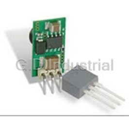
MURATA POWER SOLUTIONS LXDC2SCAAB-352

Description
Non-Isolated DC/DC Converters 2.8x2.9 Buck/boost 3.3Vo 2.8-5Vin 1.2A
Part Number
LXDC2SCAAB-352
Price
Request Quote
Manufacturer
MURATA POWER SOLUTIONS
Lead Time
Request Quote
Category
Capacitors » DC-DC Converter
Specifications
Manufacturer
Murata Power Solutions
Manufacturers Part #
LXDC2SCAAB-352
Industry Aliases
LXDC2SCAAB-352
Series
LXDC
Factory Pack Quantity
2500
Dimensions
0.11 x 0.11 x 0.05"
Efficiency
95%
Input Type
DC
Mechanical Style
Non-Isolated / POL
Mounting
SMD/SMT
Number of Outputs
1
Operating Temperature
- 40 to + 85°C
Output Amps 1
1.2 A
Output Voltage V1 Nominal
3.3 VDC
Package Type
Enclosed
Subcategory
DC-DC Converter
Datasheet

Extracted Text
LXDC2SCAAB-352 Micro DC-DC converter 1. Features Buck-Boost DC-DC converter Low EMI noise and small footprint using inductor-embedded ferrite substrate High efficiency using synchronous rectifier technology at 2.5MHz operation Wide Input voltage range : 2.8~5.0V Output voltage:3.3V Maximum load current: 1,200mA Automatic transition between buck mode and boost mode Fully protected for short-circuit, over-temperature, and under voltage 2. Description The LXDC2SCAAB-352 is a buck-boost DC-DC converter, which is suitable for a space-limited or a noise-sensitive portable application. The device utilizes an inductor-embedded ferrite substrate, and the substrate eliminates radiated EMI noise and conduction noise efficiently. The LXDC2SCAAB-352 has automatic buck-boost operations to prolong Li-ion battery life and efficiency. By switching automatically between the buck-mode operation (stepping down the voltage) when the battery is fully charged and the boost-mode operation (stepping up the voltage) as the battery is discharged, the LXDC2SCAAB-352 maximizes the overall operating voltage from the lithium battery. 3. Typical Application Circuit 1 Sep, 2015 LXDC2SCAAB-352 Micro DC-DC converter 4.Mechanical details 4-1 Outline Unit:mm Symbol Dimension Symbol Dimension L 2.8±0.2 d 0.5±0.1 W e 2.9±0.2 0.54±0.1 T 1.15MAX f 0.4±0.1 g 0.5±0.1 a h 0.26±0.2 0.39±0.1 b 0.49±0.1 i 0.36±0.2 c 0.4±0.1 j 0.44±0.1 4-2 Pin Function Pin No, Symbol I/O Description Mode=H: auto PFM mode 1 MODE Input Mode=L: Forced PWM mode 2,5,6,9 GND - Ground pin 3,4 Vout Output Regulated voltage output pin. 7 EN Input ON/OFF control pin EN=H: Device ON, EN=L: Device OFF 8 Vin Input Vin pin supplies current to the LXDC2SC internal regulator. 2 Sep, 2015 LXDC2SCAAB-352 Micro DC-DC converter 4-3 Functional Block Diagram 5. Ordering Information Part number Device Specific Feature MOQ LXDC2SCAAB-352 Standard Type T/R, 2,500pcs/R 3 Sep, 2015 LXDC2SCAAB-352 Micro DC-DC converter 6. Electrical Specification 6-1 Absolute maximum ratings Parameter symbol rating Unit Input voltage Vin 6.3 V Pin voltage EN, MODE 6.3 V o Operating Ambient temperature T -40 to +85 C OP o Operating IC temperature T -40 to +125 C IC o Storage temperature T -40 to +85 C STO 6-2 Electrical characteristics (Ta=25℃) Parameter Symbol Condition Min. Typ. Max. Unit Input voltage Vin 2.8 5.0 V Rising 1.75 1.795 UVLO voltage UVLO V Falling 1.60 1.71 Input leak current Iinoff Vin=3.8V, EN=0V 2 uA Output voltage Vout PWM mode 3.217 3.3 3.383 V accuracy Load current range Iout Vin=3.8V 1.2 A Vin=3.8V, Iout=100mA, Ripple voltage Vrpl 20 mVpp BW=100MHz Vin=3.8V, Iout=100mA Efficiency EFF 95 % EN=H, MODE=H VENH ON:Enable 1.4 Vin V EN control voltage VENL OFF:Disable 0 0.4 VMODEH Automatic PFM/PWM mode 1.4 - Vin MODE control V Voltage VMODEL Forced PWM mode 0 - 0.4 SW Frequency Fosc 2.5 MHz (*1) External capacitors (Cout: 22uF×2) should be placed near the module for proper operation. (*2) The above characteristics are tested using the test circuit in section 8. 4 Sep, 2015 LXDC2SCAAB-352 Micro DC-DC converter 6-3 Thermal and Current De-rating Information The following figure shows the power dissipation and temperature rise characteristics example. These data are measured on Murata’s evaluation board of this device at no air-flow condition. Io - Loss Characteristics (Vin=3.8V) Loss-ΔT Characteristics (Vin=3.8V) 800 50 45 700 40 600 35 500 30 25 400 20 300 15 200 10 100 5 0 0 0 100 200 300 400 500 600 0 200 400 600 800 1000 1200 Power Dissipation [mW] Iout[mA] The output current of the device may need to be de-rated if it is operated in a high ambient temperature or in a continuous power delivering application. The amount of current de-rating is highly dependent on the environmental thermal conditions, i.e. PCB design, nearby components or effective air flows. Care should o especially be taken in applications where the device temperature exceeds 85 C. o The IC temperature of the device must be kept lower than the maximum rating of 125 C. It is generally recommended to take an appropriate de-rating to IC temperature for a reliable operation. A general de-rating for the temperature of semiconductor is 80%. MLCC capacitor’s reliability and lifetime are also depending on temperature and applied voltage stress. Higher temperature and/or higher voltage cause shorter lifetime of MLCC, and the degradation can be described by the Arrhenius model. The most critical parameter of the degradation is IR (Insulation Resistance). The below figure shows MLCC’s B1 life based on a failure rate reaching 1%. It should be noted that wear-out mechanisms in MLCC capacitor is not reversible but cumulative over time. 5 Sep, 2015 Power Dissipation[mW] ΔT[℃] LXDC2SCAAB-352 Micro DC-DC converter Capacitor B1 Life vs Capacitor Case temperature 100000 Vin=5V Vin=3.8V 10000 Vin=2.8V 1000 100 10 1 0.1 20 40 60 80 100 120 Capacitor Case Temperature (℃ ) The following steps should be taken before the design fix of user’s set for a reliable operation. o 1. The ambient temperature of the device should be kept below 85 C 2. The IC temperature should be measured on the worst condition of each application. The temperature must be o kept below 125 C. An appropriate de-rating of temperature and/or output current should be taken. 3. The MLCC temperature should be measured on the worst condition of each application. Considering the above figure, it should be checked if the expected B1 life of MLCC is acceptable or not. 6 Sep, 2015 Capacitor B1 Life (Thousand Hours) LXDC2SCAAB-352 Micro DC-DC converter 7. Detailed Description Automatic buck-boost operations The LXDC2SCAAB uses 4-switch buck-boost circuit topology. The device compares the input and output voltage, and chooses the buck converter mode or boost converter mode automatically. Its transition is very smooth and seamless. Enable The device starts operation when EN is set high and starts up with soft start. For proper operation, the EN pin must be terminated to logic high and must not be left floating. Pulling the EN pin to logic low forces the device into shutdown mode. Mode selection The MODE pin allows selecting the operating mode. If the MODE pin is pulled to logic high voltage (VMODH), the converter operates automatic PFM and PWM mode. In this mode, the converter operates in PFM mode at light load current, and when the load current increase, the operating mode will change to PWM mode automatically. In this mode, the converter can work in high efficiency over wide load current range. If the MODE pin is pulled to logic low voltage (VMODL), the device operates in PWM forced mode. In this mode, the converter operates in PWM mode with the full load current range. The advantage of this mode is that the converter operates with the fixed frequency that allows simple filtering of switching frequency. In this mode, the efficiency is lower compared to the PFM mode at light load current. PFM mode at light load PWM mode at heavy load Nominal output voltage UVLO (Under Voltage Lock Out) The under voltage lockout circuit prevents the device from malfunctioning at low input voltages and the battery from excessive discharge. It disables the output stage of the converter once the falling VIN trips the under-voltage lockout threshold VUVLO which is typically 1.65V. The device starts operation once the rising VIN trips VUVLO threshold plus its hysteresis of 75 mV at typ. 1.725V. Soft Start The device has an internal soft-start function that limits the inrush current during start-up. The soft-start system progressively increases the switching on-time from a minimum pulse-width to that of normal operation. Because of this function, the output voltage increases gradually from zero to nominal voltage at start-up event. The nominal soft-start time is 3msec. 7 Sep, 2015 LXDC2SCAAB-352 Micro DC-DC converter Discharge Function To make sure the device starts up under defined conditions, the output gets discharged with a typical discharge resistor of 120 Ω whenever the device shuts down. This happens when the device is disabled or any of the protection function (thermal shutdown, under voltage lockout, over current) is triggered. Over Current Protection The converter has a hiccup-mode over current protection function. When the current in the P-Channel MOSFET is sensed to reach the current limit for 16 consecutive switching cycles, the internal protection circuit is triggered, and switching is stopped for approximately 40ms. The device then performs a soft-start cycle. Thermal Shutdown o As soon as the internal IC’s junction temperature exceeds 150 C (typ), the device goes into thermal shutdown. The device returns to its normal operation when the Internal IC’s junction temperature again falls below o 120 C(typ). 8 Sep, 2015 LXDC2SCAAB-352 Micro DC-DC converter 8. Test Circuit Cout : 22uF/6.3V GRM155R60J226M / GRM188R60J226M 9 Sep, 2015 LXDC2SCAAB-352 Micro DC-DC converter 9. Measurement Data Micro DC-DC Converter evaluation board Measurement setup The enable switch has three positions. 1. When it is toggled “ON”, the device starts operation. 2. When it is toggled “OFF”, the device stops operation and stays in shut down mode. 3. When it is set to the middle of “ON” and “OFF”, the EN pin becomes floating and can be can have an external voltage applied through the EN terminal pin on the EVB. If you don’t apply an external voltage to the EN pin, the enable switch should not to be set to the middle position. The mode switch has three states (PWM, PFM, and Open). 1. When it is shorted to “PWM” side, the device operates in PWM forced mode. 2. When it is shorted to “PFM” side, the device operates in PFM/PWM automatic mode. 3. When it is set to open, the mode pin becomes floating and can have an external voltage applied to it through the Mode terminal pin on the EVB. If you don’t apply external voltage to the Mode pin, the mode switch should not to be set to the middle position. ※The 47uF capacitor is for the evaluation kit only, and has been added to compensate for the long test cables. 10 Sep, 2015 LXDC2SCAAB-352 Micro DC-DC converter Typical Measurement Data (reference purpose only) (Ta=25℃) Efficency Vin=3.8V, PFM/PWM Operation 100 95 90 85 80 75 1 10 100 1000 Iout[mA] Output Ripple-Noise Vin=3.8V, BW : 100MHz PFM/PWM Operation 50 45 40 35 30 25 20 15 10 5 0 0 200 400 600 800 1000 1200 Iout [mA] 11 Sep, 2015 Vrpl [mV] EFF[%] LXDC2SCAAB-352 Micro DC-DC converter Load Regulation Vin=3.8V PFM/PWM Operation 3.383 3.341 3.300 3.259 3.218 0 200 400 600 800 1000 1200 Iout [mA] Load Transient Response Vin=3.8V, PFM/PWM Operation 152mV ΔIo=1.2A 12 Sep, 2015 Vout [V] LXDC2SCAAB-352 Micro DC-DC converter 10.Reliability Tests Result No. Items Specifications Test Methods QTY (NG) 1 Vibration Appearance : Solder specimens on the testing jig Resistance No severe damages (glass fluorine boards) shown in appended Fig.1 by a Pb free solder. The soldering shall be done either by iron or reflow and be conducted with care so that the soldering is uniform and free of defect such as by heat G 18 shock. (0) Frequency : 10~2000 Hz 2 Acceleration : 196 m/s Direction : X,Y,Z 3 axis Period : 2 h on each direction Total 6 h. 2 Deflection Solder specimens on the testing jig (glass epoxy boards) shown in appended Fig.2 by a Pb free solder. The soldering shall be done either by G iron or reflow and be conducted with 18 (0) care so that the soldering is uniform and free of defect such as by heat shock. Deflection : 1.6mm 3 Soldering strength 9.8 N Minimum Solder specimens onto test jig shown (Push Strength) below. Apply pushing force at 0.5mm/s until electrode pads are peeled off or ceramics are broken. Pushing force is applied to longitudinal direction. G Pushing Direction 18 (0) Specimen Jig 4 Solderability of 75% of the Immerse specimens first an ethanol Termination terminations is to be solution of rosin, then in a Pb free soldered evenly and solder solution for 3±0.5 sec. at G continuously. 245±5 °C. 18 Preheat : 150 °C, 60 sec. (0) Solder Paste : Sn-3.0Ag-0.5Cu Flux : Solution of ethanol and rosin (25 % rosin in weight proportion) 5 Resistance to Preheat Temperature : 150-180 °C Soldering Heat Preheat Period : 90+/-30 sec. (Reflow) Appearance No severe damages High Temperature : 220 °C High Temp. Period : 20sec. Satisfy Peak Temperature : 260+5/-0 °C G 18 specifications listed Specimens are soldered twice with Electrical (0) in paragraph 6-2. the above condition, and then kept in specifications room condition for 24 h before measurements. 13 Sep, 2015 LXDC2SCAAB-352 Micro DC-DC converter Result No. Items Specifications Test Methods QTY (NG) 6 High Temp. Temperature:85±2 ℃ Exposure G Period:1000+48/-0 h 18 (0) Room Condition:2~24h 7 Temperature Condition:100 cycles in the following Cycle table Step Temp(°C) Time(min) Min. G 1 Operating 30±3 18 (0) Temp.+0/-3 Max. 2 Operating 30±3 Temp.+3/-0 Appearance No severe damages 8 Humidity Temperature:85±2 ℃ Electrical Satisfy (Steady State) Humidity:80~90%RH specifications specifications listed G 18 Period:1000+48/-0 h in paragraph 6-2. (0) Room Condition:2~24h 9 Low Temp. Temperature:-40±2 ℃ Exposure Period:1000+48/-0 h G 18 Room Condition:2~24h (0) 10 C:200pF、R:0Ω ESD(Machine G TEST Voltage :+/-100V 5 Model) (0) Number of electric discharges:1 11 C:100pF、R:1500Ω ESD(Human G TEST Voltage :+/-1000V 5 Body Model) (0) Number of electric discharges:1 14 Sep, 2015 LXDC2SCAAB-352 Micro DC-DC converter Fig.1 Land Pattern d e f e d a 1 3 2 1 3 2 b 4 c 9 8 8 9 4 b g 6 7 5 a 7 6 5 h Unit:mm Symbol Dimension Symbol Dimension a 0.55 e 0.4 b 0.4 f 0.5 c 0.5 g 0.45 d 0.6 h 0.5 ・Reference purpose only. 15 Sep, 2015 LXDC2SCAAB-352 Micro DC-DC converter Fig.2 Testing board 100 Unit:mm ■: Land pattern is same as figure1 Glass-fluorine board t=1.6mm 40 Copper thickness over 35 m Mounted situation Unit:mm チップ Device 45 45 Test method Unit:mm 20 50 R230 deflection 16 Sep, 2015 LXDC2SCAAB-352 Micro DC-DC converter 11. Tape and Reel Packing 1)Dimensions of Tape (Plastic tape) Unit:mm Φ1.5+0.1 0 (0.3) 1.75±0.1 (3.5) 8.0±0.2 (3.2) (1.4) 2.0±0.05 4.0±0.1 (3.2) 4.0±0.1 引き出し方向 Feeding direction 2) Dimensions of Reel Unit:mm 2±0.5 Φ180 Φ60 Φ13±0.2 (9.0) 13.0±1.4 17 Sep, 2015 LXDC2SCAAB-352 Micro DC-DC converter 3)Taping Diagrams [1] Feeding Hole : As specified in (1) [2] Hole for chip : As specified in (1) [3] Cover tape : 50um in thickness [4] Base tape : As specified in (1) [3] [1] [2] [3] [4] 引 Feediき出 ng Hole し穴 Feeding derection 引き出し方向 Chip 部品 18 Sep, 2015 LXDC2SCAAB-352 Micro DC-DC converter 4)Leader and Tail tape A B Components 部品収納部 C Symbol Items Ratings(mm) A No components at trailer min 160 B No components at leader min 100 C Whole leader min 400 5)The tape for modules is wound clockwise with the feeding holes to the right side as the tape is pulled towards the user. 6)Packaging unit: :2,500 pcs./ reel 7) Material: Base Tape … Plastic Reel … Plastic Antistatic coating for both base tape and reel 8)Peeling of force 0.7 N max. 0.1~1.0N 165 to 180 ° Cov カバー er テ Tー apプe ベーステープ Base Tape 19 Sep, 2015 LXDC2SCAAB-352 Micro DC-DC converter NOTICE 1. Storage Conditions: To avoid damaging the solderability of the external electrodes, be sure to observe the following points. - Store products where the ambient temperature is 15 to 35 °C and humidity 45 to 75% RH. (Packing materials, In particular, may be deformed at the temperature over 40 °C.). - Store products in non corrosive gas (Cl , NH ,SO , No , etc.). 2 3 2 x - Stored products should be used within 6 months of receipt. Solderability should be verified if this period is exceeded This product is applicable to MSL1 (Based on IPC/JEDEC J-STD-020) 2. Handling Conditions: Be careful in handling or transporting the product. Excessive stress or mechanical shock may damage the product because of the nature of ceramics structure. Do not touch the product, especially the terminals, with bare hands. Doing so may result in poor solderability. 3. Standard PCB Design (Land Pattern and Dimensions): All the ground terminals should be connected to ground patterns. Furthermore, the ground pattern should be provided between IN and OUT terminals. Please refer to the specifications for the standard land dimensions. The recommended land pattern and dimensions are shown for a reference purpose only. Electrical, mechanical and thermal characteristics of the product shall depend on the pattern design and material / thickness of the PCB. Therefore, be sure to check the product performance in the actual set. When using underfill materials, be sure to check the mechanical characteristics in the actual set. 20 Sep, 2015 LXDC2SCAAB-352 Micro DC-DC converter 4. Soldering Conditions: Soldering is allowed up through 2 times. Carefully perform preheating :△ T less than 130 °C. When products are immersed in solvent after mounting, pay special attention to maintain the temperature difference within 100 °C. Soldering must be carried out by the above mentioned conditions to prevent products from damage. Contact Murata before use if concerning other soldering conditions. Reflow soldering standard conditions (example) Reflow soldering standard conditions (Example) Use rosin type flux or weakly active flux with a chlorine content of 0.2 wt % or less. 21 Sep, 2015 LXDC2SCAAB-352 Micro DC-DC converter 5. Cleaning Conditions: The product is not designed to be cleaned after soldering. 6. Operational Environment Conditions: Products are designed to work for electronic products under normal environmental conditions (ambient temperature, humidity and pressure). Therefore, products have no problems to be used under the similar conditions to the above-mentioned. However, if products are used under the following circumstances, it may damage products and leakage of electricity and abnormal temperature may occur. - In an atmosphere containing corrosive gas ( Cl NH SO NO etc.). 2, 3, x, x - In an atmosphere containing combustible and volatile gases. - In a dusty environment. - Direct sunlight - Water splashing place. - Humid place where water condenses. - In a freezing environment. If there are possibilities for products to be used under the preceding clause, consult with Murata before actual use. If static electricity is added to this product, degradation and destruction may be produced. Please use it after consideration enough so that neither static electricity nor excess voltage is added at the time of an assembly and measurement. If product malfunctions may result in serious damage, including that to human life, sufficient fail-safe measures must be taken, including the following: (1) Installation of protection circuits or other protective device to improve system safety (2) Installation of redundant circuits in the case of single-circuit failure 7. Input Power Capacity: Products shall be used in the input power capacity as specified in this specifications. Inform Murata beforehand, in case that the components are used beyond such input power capacity range . 22 Sep, 2015 LXDC2SCAAB-352 Micro DC-DC converter 8. Limitation of Applications: The products are designed and produced for application in ordinary electronic equipment (AV equipment, OA equipment, telecommunication, etc). If the products are to be used in devices requiring extremely high reliability following the application listed below, you should consult with the Murata staff in advance. - Aircraft equipment. - Aerospace equipment - Undersea equipment. - Power plant control equipment. - Medical equipment. - Transportation equipment (vehicles, trains, ships, etc.). - Automobile equipment which includes the genuine brand of car manufacture, car factory-installed option and dealer-installed option. - Traffic signal equipment. - Disaster prevention / crime prevention equipment. - Data-procession equipment. - Application which malfunction or operational error may endanger human life and property of assets. - Application which related to occurrence the serious damage - Application of similar complexity and/ or reliability requirements to the applications listed in the above. ! Note: Please make sure that your product has been evaluated and confirmed against your specifications when our product is mounted to your product. Product specifications are subject to change or our products in it may be discontinued without advance notice. This catalog is for reference only and not an official product specification document, therefore, please review and approve our official product specification before ordering this product. 23 Sep, 2015
Frequently asked questions
How does Electronics Finder differ from its competitors?

Is there a warranty for the LXDC2SCAAB-352?
Which carrier will Electronics Finder use to ship my parts?
Can I buy parts from Electronics Finder if I am outside the USA?
Which payment methods does Electronics Finder accept?
Why buy from GID?

Quality
We are industry veterans who take pride in our work

Protection
Avoid the dangers of risky trading in the gray market

Access
Our network of suppliers is ready and at your disposal

Savings
Maintain legacy systems to prevent costly downtime

Speed
Time is of the essence, and we are respectful of yours
Related Products
DC/DC 8-36VIN/3.3VOUT .5A SIP 7803SR-C
DC/DC 8-36VIN/3.3VOUT .5A HSIP 7803SRH-C
DC/DC 8-36VIN/5VOUT .5A SIP 7805SR-C
DC/DC 8-36VIN/5VOUT .5A HSIP 7805SRH-C
4.8 W, 15 -36 VDC VIN, SINGLE OUTPUT, 12 VDC@0.4 A DC-DC CONVERTER 7812SR-C
4.8 W, 15 -36 VDC VIN, SINGLE OUTPUT, 12 VDC@0.4 A DC-DC CONVERTER 7812SRH-C
Request a Quote

The quote request has been received
Close

Facing challenges or have inquiries? Feel free to contact us!
Call Us +1-469-283-2440
What they say about us
FANTASTIC RESOURCE
One of our top priorities is maintaining our business with precision, and we are constantly looking for affiliates that can help us achieve our goal. With the aid of GID Industrial, our obsolete product management has never been more efficient. They have been a great resource to our company, and have quickly become a go-to supplier on our list!
Bucher Emhart Glass
EXCELLENT SERVICE
With our strict fundamentals and high expectations, we were surprised when we came across GID Industrial and their competitive pricing. When we approached them with our issue, they were incredibly confident in being able to provide us with a seamless solution at the best price for us. GID Industrial quickly understood our needs and provided us with excellent service, as well as fully tested product to ensure what we received would be the right fit for our company.
Fuji
HARD TO FIND A BETTER PROVIDER
Our company provides services to aid in the manufacture of technological products, such as semiconductors and flat panel displays, and often searching for distributors of obsolete product we require can waste time and money. Finding GID Industrial proved to be a great asset to our company, with cost effective solutions and superior knowledge on all of their materials, it’d be hard to find a better provider of obsolete or hard to find products.
Applied Materials
CONSISTENTLY DELIVERS QUALITY SOLUTIONS
Over the years, the equipment used in our company becomes discontinued, but they’re still of great use to us and our customers. Once these products are no longer available through the manufacturer, finding a reliable, quick supplier is a necessity, and luckily for us, GID Industrial has provided the most trustworthy, quality solutions to our obsolete component needs.
Nidec Vamco
TERRIFIC RESOURCE
This company has been a terrific help to us (I work for Trican Well Service) in sourcing the Micron Ram Memory we needed for our Siemens computers. Great service! And great pricing! I know when the product is shipping and when it will arrive, all the way through the ordering process.
Trican Well Service
GO TO SOURCE
When I can't find an obsolete part, I first call GID and they'll come up with my parts every time. Great customer service and follow up as well. Scott emails me from time to time to touch base and see if we're having trouble finding something.....which is often with our 25 yr old equipment.
ConAgra Foods