

 Manufacturers
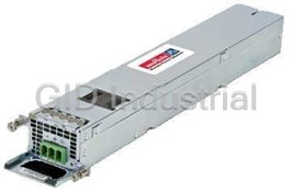
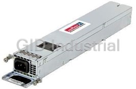
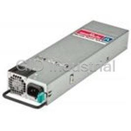
MURATA POWER SOLUTIONS MVAC250-24AFD

Description
250 W, TRIPLE OUTPUT, 24 VDC@10.4 A | 12 VDC@1 A | 5 VDC@2:00 AM AC-DC POWER SUPPLY
Part Number
MVAC250-24AFD
Price
Request Quote
Manufacturer
MURATA POWER SOLUTIONS
Lead Time
Request Quote
Category
Circuit Protection » AC-DC Power Supply
Specifications
Manufacturer
Murata Power Solutions
Manufacturers Part #
MVAC250-24AFD
Series
MVAC250
Factory Pack Quantity
18
Cooling Method
Air-Cooled, Convection
Dimensions
5.00 x 3.00 x 1.18"
Efficiency
93%
Input Voltage Nominal
230 VAC, 115 VAC
Isolation
4000 VAC
Mechanical Style
PFC Front End
Mounting
Chassis
Number of Outputs
3
Operating Temperature
- 10 to + 70°C
Output Amps 1
10.4 A
Output Amps 2
1 A
Output Amps 3
2:00 AM
Output Voltage V1 Nominal
24 VDC
Output Voltage V2 Nominal
12 VDC
Output Voltage V3 Nominal
5 VDC
Power
250 W
Subcategory
AC-DC Power Supply
Datasheet

Extracted Text
Recommended Alternative: MVAC250 Series PQC250 Series www.murata-ps.com 250W 3" x 5" High Density AC-DC Power Supply Converter ORDERING GUIDE Main Output Fan Output Aux Output Model Number Natural Convection Cooling Forced Air Cooling (V1) (V2) (V3) MVAC250-12F 12V 12V MVAC250-24F 24V 12V MVAC250-48F 50V 12V MVAC250-12AF 12V 12V 5V 170W 250W @ 250LFM MVAC250-12AFD* 12V 12V 5V MVAC250-24AFD* 24V 12V 5V MVAC250-48AFD* 50V 12V 5V # MVAC250-24AFT 24V 12V 5V To Be Discontinued* *LAST TIME BUY: 4/1/2018. FEA FEATURES TURES MVAC-COVER Optional cover kit assembly; see MVAC-COVER datasheet for details IEC60601 Ed.3 medical (2 x MOPP Pri-Sec) * Refer to page 2 for current sharing model number MVAC250-xxAFD notes. EN60950 ITE safety approved # CCC Certifi cation is not available for these models. 250W compact high density INPUT CHARACTERISTICS Parameter Conditions Min. Typ. Max. Units 3" x 5" standard footprint Single phase 90 115/230 264 Vac High effi ciency up to 94% Input Voltage Operating Range DC 127 300 Vdc Remote sense Input Frequency 47 50/60 63 Hz Turn-on Input Voltage Input rising 80 90 Remote On/Off, Power OK (MVAC250-xxAFx) Vac Turn-off Input Voltage Input falling 70 80 Universal AC input with active PFC Input Current 90Vac input, full load all outputs 3.4 A 7 No Load Input Power (MVAC250-xxAFD) (PS_ON = OFF, 5V_Aux = 0A) 1.5 2.0 W Less than 1U high – 1.4" Inrush Current At 264Vac, at 25°C cold start 15 Apk Convection cooled operation up to 170W Power Factor At 230Vac, full load 0.96 Isolated 12V@1A fan output OUTPUT CHARACTERISTICS Isolated 5V@2A standby/auxiliary output with Main Output Maximum Load Line, Load, Cross Typical Effi ciency models MVAC250-xxAFx Model Number Load Current Voltage (V1) Capacitance Regulation @230Vac MVAC250-12F 12V 0.4 to 20.8A 0 to 1500µF ± 1% 93% RoHS compliant MVAC250-24F 24V 0.2 to 10.4A 0 to 300µF ± 1% 93% Active inrush protection MVAC250-24AFT MVAC250-48F 50V 0.1 to 5.0A 0 to 82µF ± 1% 94% Current sharing option MVAC250-12AF 12V 0 to 20.8A 0 to 1500uF ± 1% 93% 6 6 MVAC250-12AFD 12V @ 10.4A 0 to 20.8A 0 to 1500µF ± 1.5% 93% DESCRIPTION 6 6 MVAC250-24AFD 24V @ 5.2A 0 to 10.4A 0 to 300µF ± 1.5% 93% 6 6 The MVAC250 series switching power supplies MVAC250-48AFD 50V @ 2.5A 0 to 5.0A 0 to 68µF +3.0% / –1.5% 94% utilize advanced component and circuit Main Output Characteristics (all models) technologies to deliver high effi ciency. Designed Parameter Conditions Typ. Max. Units 9 for medical, computing, communications, telecom Transient Response 50% load step, 1A/µsec slew rate ± 5 % and other OEM applications to satisfy 1U height Settling Time to 1% of Nominal 500 µsec Turn On Delay After application of input power 3 sec design considerations, the MVAC250 Series 5 Output Voltage Rise Monotonic 50 measures only 3.0" x 5.0" x 1.40". All models msec Output Holdup 120Vac/60Hz, full load 20 offer universal AC input with active power factor Temperature Coeffi cient 0.02 %/°C correction (PFC) and compliance to worldwide 1 Ripple Voltage & Noise 1 % safety and EMC standards. Compensates for up to 0.5V of lead drop with Remote Sense remote sense connected. Protected against 500 mV www.murata-ps.com/en/3d/acdc.html short circuit and reverse connection. www.murata-ps.com/en/3d/acdc.html www.murata-ps.com/en/3d/acdc.html Auxiliary Output Characteristics (varies by model) www.murata-ps.com/en/3d/acdc.html Aux Output Line, Load, Cross Ripple Voltage & Auxiliary Output Load Current Load Capacitance www.murata-ps.com/en/3d/acdc.html 8 3 1 Voltage Regulation Noise www.murata-ps.com/en/3d/acdc.html Fan (V2) all models 12V 0 to 1A 0 to 220µF ± 10% 2% Aux (V3) – MVAC250-xxAFx 5V 0 to 2A 0 to 220µF ± 5% 1% Available now at www.murata-ps.com/en/3d/acdc.html CB Test Certifi cate REG.-Nr C457 . and Test Report For full details go to www.murata-ps.com/rohs www.murata-ps.com/support MVAC250.C03 Page 1 of 9 MVAC250 Series 250W 3" x 5" High Density AC-DC Power Supply Converter ENVIRONMENTAL CHARACTERISTICS Parameter Conditions Min. Typ. Max. Units Storage Temperature Range -40 85 See power rating curves -10 70 °C Operating Temperature Range Start up -20 Operating Humidity Non-condensing 10 95 % Operating Altitude -200 5000 m MTBF Telcordia SR-332 M1C3 @25°C 474K Hours Operating, MIL-HBK-810E Complies Shock Non-operating, MIL-HBK-810E Complies Operational Vibration IEC-68-2-27 standard Complies to levels of IEC721-3-2 IEC60601-1 (Ed. 3) – CB Cert & Report Safety – Medical Standards ANSI/AAMI ES60601-1 (2005+ C1:2005+A2:10) 2 x MOPP (Primary-Secondary) CAN/CSA 22.2 No. 60601-1 (2008) 3rd Edition EN60601-1:2006+CORR:2010 UL60950-1:, 2nd Edition, 2011-12-19 CSA22.2 No..60950-1-07, 2nd Edition, 2001-12. Safety – ITE Standards EN60950-1:2006+A11:2009/A1/2010/A12:2011 IEC 60950 (ed.2), IEC60950 (ed.2);am1 CE Marking per LVD Warranty 2 years Outside Dimensions 3.0" x 5.0" x 1.4" (76.2mm x 127mm x 35.6mm) Weight MVAC250-xxF: 0.73 lbs (332.9g); MVAC250-xxAFD: 0.76 lbs (344.7g); MVAC250-xxAFT 0.78 lbs (352.7g) RESIDUAL RISK (PER ISO 14971 & IEC60601-1) FOR USER CONSIDERATION Fault Condition Residual Risk Complies Contact your Murata salesperson for details PROTECTION CHARACTERISTICS Parameter Conditions Min. Typ. Max. Units V1 (main output) latching 110 125 % 4 Over Voltage Protection V3 (aux output: MVAC250-xxAFx) latching 5.5 7.5 V 4 Over Current Protection V1, hiccup mode 110 130 %Amax Over Temperature Protection Auto-recovery Complies Remote Sense Short Circuit Protection Complies Remote Sense Reverse Connection Protection Complies ISOLATION CHARACTERISTICS Parameter Conditions Min. Typ. Max. Units Primary to Chassis 1500 Primary to Secondary (2xMOPP) 4000 Isolation Vac Secondary to Chassis 500 Output to Output 500 MVAC250-xxAFD 300 Earth Leakage Current (under single fault condition): MVAC250-xxAF; -xxAFT 300 264Vac, 60Hz, 25°C MVAC250-xxF 350 µA MVAC250-xxAFD 150 Earth Leakage Current (under normal conditions): MVAC250-xxAF; -xxAFT 150 264Vac, 60Hz, 25°C MVAC250-xxF 250 CURRENT SHARING OPTION – MVAC250-xxAFD ONLY Model Number Description Main Output: Current share is achieved using the droop method. Nominal output voltage is achieved at 50% load and output voltage increases/ drops at a rate of: • 48mv per amp for 12V output • 192mV per amp for 24V output MVAC250-12AFD • 800mV per amp for 50V output. Startup of parallel power supplies is not internally synchronized. If more than 250W combined power is needed, start-up synchronization must be MVAC250-24AFD provided by using a common PS_ON signal. To account for ±10% full load current sharing accuracy and the reduction in full load output voltage due to droop, available output power must be derated by 15% when units are operated in parallel. Current sharing can be achieved with or without remote sense connected to the common load. If ORing protection is desired, please contact Murata sales for external ORing FET board or external MVAC250-48AFD ORing FET reference circuit design. Aux (V3) output can be tied together for redundancy but total combined output power must not exceed 10W, external ORing devices must be used. Fan (V2) can be tied together for redundancy but total combined output power must not exceed 12W, external ORing diodes can be used. www.murata-ps.com/support MVAC250.C03 Page 2 of 9 MVAC250 Series 250W 3" x 5" High Density AC-DC Power Supply Converter EMISSIONS AND IMMUNITY Characteristic Standard Compliance Input Current Harmonics IEC/EN 61000-3-2 Class A Voltage Fluctuation and Flicker IEC/EN 61000-3-3 Complies EN 55022 Class B Conducted Emissions FCC Part 15 Class B ESD Immunity IEC/EN 61000-4-2 Level 4, Criterion 2 Radiated Field Immunity IEC/EN 61000-4-3 Level 3, Criterion A Electrical Fast Transient Immunity IEC/EN 61000-4-4 Level 4, Criterion A Surge Immunity IEC/EN 61000-4-5 Level 3, Criterion A Radiated Field Conducted Immunity IEC/EN 61000-4-6 Level 3, 10V/m, Criterion A Magnetic Field Immunity IEC/EN 61000-4-8 Level 3, Criterion A Voltage dips, interruptions IEC/EN 61000-4-11 Level 3, Criterion B EMI CONSIDERATIONS For optimum EMI performance, the power supply should be mounted to a metal plate grounded to all 4 mounting holes of the power supply. To comply with safety standards, this plate must be properly grounded to protective earth (see mechanical dimension notes). Pre-compliance testing has shown the stand-alone power supply to comply with EN55022 Class A radiated emissions. Class B radiated emissions are achievable with a metal enclosure. Radiated emission results vary with system enclosure and cable routing paths. SAFETY CONSIDERATIONS 1. This power supply is a component level power supply intended for use in Class I or Class II applications. Secondary ground traces need to be suitably isolated from primary ground traces when used in Class II applications. 2. When the power supply is used in Class II equipment, all ground traces and components connected to the primary side are considered primary for spacing and insulation considerations. STATUS AND CONTROL SIGNALS – MVAC250-xxAFD ONLY Parameter Models Conditions All models except This signal must be pulled low (sink current >2mA) to +5V_AUX_RTN to turn on the main and Fan (V2) output. The +5V_AUX output is independent as noted below. of the PS_ON signal and comes up automatically when the input AC or input DC voltage is applied within their specified operating ranges. PS_ON This pin is pulled high internally and so all three outputs (main, Fan output and +5V_AUX) come up automatically when the input AC or input DC voltage MVAC250-xxAFT is applied within their specified operating ranges. Pulling this pin low (sink current >2mA) to +5V_AUX_RTN will disable the main and fan outputs. Open collector logic goes high 50-200 msec after main output is in regulation; it goes low at least 6 msec before loss of regulation. Internal 10K pull PWR_OK All models up to +5V_AUX is provided. Applications using PWR_OK signal should maintain a minimum load of 5W on the main or fan output. 1. Noise and ripple is measured at an oscilloscope jack on the output, 20MHz bandwidth, and with 5. 24V and 50V models may exhibit up to 5% turn on overshoot for loads less than 4% of full load. 0.1µF ceramic and 10µF aluminum electrolytic capacitors across the output pins. 6. See current sharing option section for droop characteristics. 2. Unless otherwise specified all measurements are taken at 120Vac input and 25°C ambient 7. No load Input power varies by model and by input line. Measurement is difficult to make due to burst temperature. mode operation. Please contact Murata sales if additional information is required. 3. Fan (V2) regulation band applies from 0.1A to 1A load with a minimum of 10W load on the main 8. All three output returns are isolated from each other (see isolation characteristics section); the returns (V1) output. may be tied together externally. 4. Fan (V2) has overvoltage protection (tracking V1) and short circuit protection. Overloading the Fan 9. Load steps beginning from combined loads on the main and fan outputs of less than 5W may (V2) output can result in permanent damage to the unit. result in transient undershoots outside of the spec limits. PART NUMBER STRUCTURE MV A x yyy zz hhh - Modification Code Options Murata Manufacturing Corp. A = Aux 5V Standby Voltage F = Aux 12V Fan Output D = Droop Current Share Form Factor Outline T = Terminal Output Connector A = 2x4", 3x5", or 4x7" R = Terminal Output Connector with Internal Or-ing Solution and Droop Current Share Main Output Voltage (V) Outline Detail (12, 24, 28, or 50) B & D = 2x4" C = 3x5" Output Power (W) F = 4x7" (40, 65, 120, 160, 250, 400, or 750) www.murata-ps.com/support MVAC250.C03 Page 3 of 9 MVAC250 Series 250W 3" x 5" High Density AC-DC Power Supply Converter PERFORMANCE DATA MVAC250-12F Efficiency MVAC250-24F Efficiency 95 95 93 93 91 91 90 Vin 90 Vin 115 Vin 115 Vin 89 89 230 Vin 230 Vin 87 87 85 85 83 83 81 81 0 10 20 30 40 50 60 70 80 90 100 0 10 20 30 40 50 60 70 80 90 100 Load % Load % Inrush Current MVAC250-48F Efficiency 95 93 91 90 Vin 115 Vin 89 230 Vin 87 85 83 81 0 10 20 30 40 50 60 70 80 90 100 Load % Time: 100 msec/div, Ch1: 500 V/div, Ch4: 20 A/div, Vin: 264 VAC, Ipk = 15.1 A AC applied at peak of sine wave www.murata-ps.com/support MVAC250.C03 Page 4 of 9 Efficiency % Efficiency % Efficiency % MVAC250 Series 250W 3" x 5" High Density AC-DC Power Supply Converter THERMAL CONSIDERATIONS System thermal management is critical to the performance and reliability of the MVAC series power supplies. Performance derating curves are provided which can be used as a guideline for what can be achieved in a system confi guration with controlled airfl ow at various input voltage conditions. The air fl ow curves are generated using an AMCA 210-99 and ASHRAE 51-1999 compliant wind tunnel with heated inlet air and a controlled CFM providing a duct test section having a calculated average LFM. A correlation between the test setup and the actual system environment is paramount to understanding what can be achieved in an actual system. In a power supply of this density, cooling air moving both through the unit as well as around the unit strongly infl uences local temperatures. The wind tunnel test setup was constructed to produce a fl ow with a slight back pressure to induce both fl ow conditions by providing a small gap between the power supply and duct walls of 0.5" (13mm). The optimal and characterized airfl ow direction is from the input connector to the output connector (see diagram below). The P-Q fl ow curve for this test setup is also shown below. P-Q CURVE, DUCTED FLOW 13mm [0.5in] all sides 0.0100 Air Flow Power Supply 0.0075 * 0.0050 Ambient Temperature 0.0025 Measurement 0.0000 0 2.5 5 7.5 10 12.5 15 17.5 20 22.5 Output Connector Input Connector 64mm [2.5in] AIRFLOW-(CFM @ 0.075 lbs/cu ft air density) The natural convection data is obtained from a horizontally mounted power supply with un-obstructed fl ow at room temperature. At elevated temperature the power supply data is taken while it is surrounded by a large vented enclosure to minimize forced cross fl ows inherent in the elevated temperature test system. Power Rating at 230Vac Power Rating at 120Vac 275 275 250 250 225 225 200 200 175 175 150 Nat Conv 150 Nat Conv 125 125 250LFM 250LFM 100 100 75 75 50 50 10 20 30 40 50 60 70 10 20 30 40 50 60 70 Ambient Temperature (Degrees C) Ambient Temperature (Degrees C) Power Rating at 100Vac Power Rating at 90Vac 275 275 250 250 225 225 200 200 175 175 150 150 Nat Conv Nat Conv 125 125 250LFM 250LFM 100 100 75 75 50 50 10 20 30 40 50 60 70 10 20 30 40 50 60 70 Ambient Temperature (Degrees C) Ambient Temperature (Degrees C) www.murata-ps.com/support MVAC250.C03 Page 5 of 9 Output Power (Watts) Output Power (Watts) Output Power (Watts) Output Power (Watts) Static Pressure (in. w.g.) MVAC250 Series 250W 3" x 5" High Density AC-DC Power Supply Converter WIRING DIAGRAM FOR OUTPUT Dotted lines show optional remote sense connections. Optional remote sense lines can be attached to a load that is a distance away from the power supply to improve regulation at the load. +Remote Sense +Remote Sense +DC out +DC out J3 pin 5 J3 pin 5 MVAC250-xxAFx MVAC250-xxF J2 pins 1-6 J2 pins 1-6 Main Output Load Main Output Load J2 pins 7-12 DC out return J2 pins 7-12 DC out return -Remote Sense -Remote Sense J3 pin 6 J3 pin 6 2K49 10K0 J3 pin 1 +5V_AUX 10 100 J3 pin 4 PS_ON +5V logic circuitry CTR~100 +5V_AUX >2mA 1N0 10K0 100 J3 pin 2 5 PWR_OK FET, BJT, wire 6 or switch (debounced ) to turn on +DC out 2 and +12V_fan 74LVC2G07 J3 pin 8 +5V_AUX_RTN J3 pin 7 +12V_Fan J3 pin 7 +12V_Fan Fan or Fan or other load other load J3 pin 3 +12V_FAN_RTN J3 pin 3 +12V_FAN_RTN APPLICATION NOTE Document Number Description Link ACAN-42 MVAC Series External ORing FET Reference Circuit www.murata-ps.com/data/apnotes/acan-42.pdf www.murata-ps.com/support MVAC250.C03 Page 6 of 9 MVAC250 Series 250W 3" x 5" High Density AC-DC Power Supply Converter MECHANICAL DIMENSIONS – MVAC250-xxF ONLY 127.00 ±0.25 MOUNTING SLOTS 5.000 ±0.010 WIDTH 3.96 ±0.13 0.156 ±0.005 C 0.13 C 0.13 A 0.13 MAX SCREW HEAD [ 0.005] [ 0.005] [ 0.005] DIAMETER 7.40 MTG4 MTG1 MOUNTING GRIDS A B C 4.50 x 2.50 114.30 [4.500] 63.50 [2.500] 6.35 [0.250] TB1 4.55 x 2.55 115.57 [4.550] 64.77 [2.550] 5.72 [0.225] J1 PIN 1 PIN 2 J2 J2 REMOVED PIN12 6 12 1-6 +DC_OUT 76.20 ±0.25 B 0.13 J1 5 11 7-12 +DC_OUT_RTN 3.000 ±0.010 [ 0.005] PIN 3 J2 1 PIN1 3 9 J3 PIN 1 1 7 J3 PIN 8 J3 21 1 DO NOT USE MTG2 MTG3 PRIMARY 43 2 DO NOT USE HEATSINK 6 5 3 +12V_FAN_RTN NOTE 3 ! 8 7 4 DO NOT USE 5 +REMOTE_SENSE 6 -REMOTE_SENSE 7 +12V_FAN 30.0 ±0.25 8 DO NOT USE 1.181 ±0.010 ALL DIMENSIONS ARE IN MM [IN]. 5.56 ±0.13 0.219 ±0.005 SAFETY CONSIDERATION NOTES: 1. Protective bonding conductor from the end product protective earthing terminal must be tied to TB1. For optimum EMI performance, while maintaining Class I safety isolation all 4 mounting holes must be tied to the end product protective earthing terminal. To maintain Class II safety isolation mounting holes MTG1 and MTG2 need to be isolated from protective earth and should use standoffs of non-conductive material. 2. This power supply requires mounting standoffs of minimum 6mm in height. If there is risk of chassis deformation or shorter standoff height is required, an appropriate insulator must be used under the power supply with adequate extension beyond the outline of the power supply. In all cases, the applicable safety standards must be applied to ensure proper creepage and clearance requirements are met. 3. The primary heatsink is considered a live primary circuit, and should not be touched. It is recommended that the primary heatsink be kept at least 3.5mm from chassis and 7mm from secondary circuits. In all cases, the applicable safety standards must be applied to ensure proper creepage and clearance requirements are met. 4. This product is subject to the following operating requirements and the Life and Safety Critical Application Sales Policy: Refer to: http://www.murata-ps.com/requirements/ 5. Used only in non-tropical conditions. 6. Double pole/neutral fusing. Dimensions: 3.0" x 5.0" x 1.4" (76.2mm x 127mm x 35.6mm) INPUT/OUTPUT CONNECTOR AND SIGNAL SPECIFICATION AND MATING CONNECTORS – MVAC250-xxF ONLY Connector PIN Description Mating Housing Crimp terminal/pins 1 AC Neutral Molex 0008500105 (18-24 AWG) Input Connector J1 : Molex 0009930300 Molex 26-62-4030 3 AC Line Molex 0008500107 (22-26 AWG) Output Connector J2 : 1,2,3,4,5,6 +DC_OUT Molex 0039012125 Molex 0039000038 Molex 39-28-1123 7,8,9,10,11,12 +DC_OUT_RTN 1 DO NOT USE 2 DO NOT USE 3 +12V_FAN_RTN 4 DO NOT USE Output Connector J3: Molex 0901420008 Molex 0901190109 Molex 90130-1108 5 + Remote Sense 6 – Remote Sense 7 +12V_FAN 8 DO NOT USE www.murata-ps.com/support MVAC250.C03 Page 7 of 9 82 04 MVAC250 Series 250W 3" x 5" High Density AC-DC Power Supply Converter MECHANICAL DIMENSIONS – MVAC250-xxAF & MVAC250-xxAFD 127.00 ±0.25 MOUNTING SLOTS 5.000 ±0.010 WIDTH 3.96 0.13 [0.156 0.005] C 0.13 C 0.13 A 0.13 MAX SCREW HEAD [ 0.005] [ 0.005] [ 0.005] DIAMETER 7.40 MTG1 MTG4 MOUNTING GRIDS A B C 4.50 x 2.50 114.30 [4.500] 63.50 [2.500] 6.35 [ 0.250] TB1 4.55 x 2.55 115.57 [4.550] 64.77 [2.550] 5.72 [ 0.225] J1 PIN 1 PIN 2 J2 J2 REMOVED PIN12 6 12 1-6 +DC_OUT J1 76.20 ±0.25 B 0.13 PIN 3 5 11 7-12 +DC_OUT_RTN 3.000 ±0.010 [ 0.005] J2 4 10 PIN1 39 J3 28 PIN 1 17 J3 PIN 8 J3 21 1 +5V_AUX MTG2 MTG3 PRIMARY 43 2 PWR_OK HEATSINK 65 3 +12V_FAN_RTN NOTE 3 ! 87 4 PS_ON 5 +REMOTE_SENSE 6 -REMOTE_SENSE 7 +12V_FAN 30.0 ±0.25 8 +5V_AUX_RTN 1.181 ±0.010 ALL DIMENSIONS ARE IN MM [IN]. 5.56 ±0.13 0.219 ±0.005 SAFETY CONSIDERATION NOTES: 1. Protective bonding conductor from the end product protective earthing terminal must be tied to TB1. For optimum EMI performance, while maintaining Class I safety isolation all 4 mounting holes must be tied to the end product protective earthing terminal. To maintain Class II safety isolation mounting holes MTG1 and MTG2 need to be isolated from protective earth and should use standoffs of non-conductive material. 2. This power supply requires mounting standoffs of minimum 6mm in height. If there is risk of chassis deformation or shorter standoff height is required, an appropriate insulator must be used under the power supply with adequate extension beyond the outline of the power supply. In all cases,the applicable safety standards must be applied to ensure proper creepage and clearance requirements are met. 3. The primary heatsink is considered a live primary circuit, and should not be touched. It is recommended that the primary heatsink be kept at least 3.5mm from chassis and 7mm from secondary circuits. In all cases, the applicable safety standards must be applied to ensure proper creepage and clearance requirements are met. 4. This product is subject to the following operating requirements and the Life and Safety Critical Application Sales Policy: Refer to: http://www.murata-ps.com/requirements/ 5. Used only in non-tropical conditions 6. Double pole/neutral fusing. Dimensions: 3.0" x 5.0" x 1.4" (76.2mm x 127mm x 35.6mm) INPUT/OUTPUT CONNECTOR AND SIGNAL SPECIFICATION AND MATING CONNECTORS – MVAC250-xxAF AND MVAC250-xxAFD MODELS Connector PIN Description Mating Housing Crimp terminal/pins Input Connector J1: 1 AC Neutral Molex 0008500105 (18-24 AWG) Molex 0009930300 Molex 26-62-4030 3 AC Line Molex 0008500107 (22-26 AWG) 1,2,3,4,5,6 +DC_OUT Output Connector J2: Molex 0039012125 Molex 0039000038 Molex 39-28-1123 7,8,9,10,11,12 +DC_OUT_RTN 1 +5V_AUX 2 PWR_OK 3 +12V_FAN_RTN Output Connector J3: 4 PS_ON Molex 0901420008 Molex 0901190109 Molex 90130-1108 5 + Remote Sense 6 – Remote Sense 7 +12V_FAN 8 +5V_AUX_RTN www.murata-ps.com/support MVAC250.C03 Page 8 of 9 MVAC250 Series 250W 3" x 5" High Density AC-DC Power Supply Converter MECHANICAL DIMENSIONS – MVAC250-xxAFT 127.00 ±0.25 MOUNTING SLOTS WIDTH 3.96 0.13 5.000 ±0.010 [0.156 0.005] C 0.13 C 0.13 A 0.13 MAX SCREW HEAD [ 0.005] [ 0.005] [ 0.005] DIAMETER 7.40 MTG1 MTG4 MOUNTING GRID A B C 4.50 x 2.50 114.30 [4.500] 63.50 [ 2.500] 6.35 [0.250] SECONDARY 4.55 x 2.55 115.57 [4.550] 64.77 [ 2.550] 5.72 [0.225] HEATSINK TB1 NOTE 3 ! J1 PIN 1 PIN 2 J2 REMOVED TERMINAL + J2 (#6-32 INSERTS) 76.20 ±0.25 J1 +DC_OUT + B 0.13 J2 3.000 ±0.010 PIN 3 +DC_OUT_RTN TERMINAL - - [ 0.005] J3 PIN 1 J3 PIN 8 J3 MVAC250-xxAFT/R 21 1 +5V_AUX MTG2 PRIMARY MTG3 4 3 2 PWR_OK HEATSINK 6 5 3 +12V_FAN_RTN NOTE 3 ! 87 PS_ON 4 +REMOTE_SENSE 5 -REMOTE_SENSE 6 +12V_FAN 7 30.0 ±0.25 +5V_AUX_RTN 8 1.181 ±0.010 ALL DIMENSIONS ARE IN MM [IN]. 5.56 ±0.13 0.219 ±0.005 SAFETY CONSIDERATION NOTES: 1. Protective bonding conductor from the end product protective earthing terminal must be tied to TB1. For optimum EMI performance, while maintaining Class I safety isolation all 4 mounting holes must be tied to the end product protective earthing terminal. To maintain Class II safety isolation mounting holes MTG1 and MTG2 need to be isolated from protective earth and should use standoffs of non-conductive material. 2. This power supply requires mounting standoffs of minimum 6mm in height. If there is risk of chassis deformation or shorter standoff height is required, an appropriate insulator must be used under the power supply with adequate extension beyond the outline of the power supply. In all cases,the applicable safety standards must be applied to ensure proper creepage and clearance requirements are met. 3. The primary heatsink is considered a live primary circuit, and should not be touched. It is recommended that the primary heatsink be kept at least 3.5mm from chassis and 7mm from secondary circuits. In all cases, the applicable safety standards must be applied to ensure proper creepage and clearance requirements are met. 4. This product is subject to the following operating requirements and the Life and Safety Critical Application Sales Policy: Refer to: http://www.murata-ps.com/requirements/ 5. Used only in non-tropical conditions 6. Double pole/neutral fusing. Dimensions: 3.0" x 5.0" x 1.4" (76.2mm x 127mm x 35.6mm) INPUT/OUTPUT CONNECTOR AND SIGNAL SPECIFICATION AND MATING CONNECTORS – MVAC250-xxAFT Connector Pin Description Mating Housing Crimp Terminal/Pins Input Connector J1: 1 AC Neutral Molex 0008500105 (18-24 AWG) Molex 0009930300 Molex 26-62-4030 Molex 0008500107 (22-26 AWG) 3 AC Line + +DC_OUT Output Connector J2 – +DC_OUT_RTN 1 +5V_AUX 2 PWR_OK 3 +12V_FAN_RTN Output Connector J3: 4 PS_ON Molex 0901420008 Molex 0901190109 Molex 90130-1108 5 + Remote Sense 6 – Remote Sense 7 +12V_FAN 8 +5V_AUX_RTN Murata Power Solutions, Inc. This product is subject to the following operating require- 11 Cabot Boulevard, Mansfield, MA 02048-1151 U.S.A. ments and the Life and Safety Critical Application Sales ISO 9001 and 14001 REGISTERED Policy. Refer to: http://www.murata-ps.com/requirements/ Murata Power Solutions, Inc. (“Murata”) makes no representation that the use of its products in the circuits described herein, or the use of other technical information contained herein, will not infringe upon existing or future patent rights. The descriptions contained herein do not imply the granting of licenses to make, use, or sell equipment constructed in accordance therewith. Buyer represents and agrees that it has all the necessary expertise to create and implement safeguards that anticipate dangerous consequences of failures, monitor failures and their consequences, lessen the likelihood of failures that might cause harm, and take appropriate remedial actions. Buyer will fully indemnify Murata, its affiliated companies, and its representatives against any damages arising out of the use of any Murata products in safety-critical applications. Specifications are subject to change without notice. © 2017 Murata Power Solutions, Inc. www.murata-ps.com/support MVAC250.C03 Page 9 of 9
Frequently asked questions
How does Electronics Finder differ from its competitors?

Is there a warranty for the MVAC250-24AFD?
Which carrier will Electronics Finder use to ship my parts?
Can I buy parts from Electronics Finder if I am outside the USA?
Which payment methods does Electronics Finder accept?
Why buy from GID?

Quality
We are industry veterans who take pride in our work

Protection
Avoid the dangers of risky trading in the gray market

Access
Our network of suppliers is ready and at your disposal

Savings
Maintain legacy systems to prevent costly downtime

Speed
Time is of the essence, and we are respectful of yours
Related Products
400 W, SINGLE OUTPUT, 12 VDC@33.3 A OEM/COMMERCIAL ENCLOSED AC-DC POWER SUPPLY
400 W, SINGLE OUTPUT, 12 VDC@33.3 A OEM/COMMERCIAL ENCLOSED AC-DC POWER SUPPLY
1200 W, SINGLE OUTPUT, 12 VDC@98.3 A AC-DC POWER SUPPLY
1200 W, SINGLE OUTPUT, 12 VDC@98.3 A AC-DC POWER SUPPLY
1200 W, Single Output, 12 VDC@98.3 A AC-DC Power Supply
1200 W, Single Output, 12 VDC@98.3 A AC-DC Power Supply
Request a Quote

The quote request has been received
Close

Facing challenges or have inquiries? Feel free to contact us!
Call Us +1-469-283-2440
What they say about us
FANTASTIC RESOURCE
One of our top priorities is maintaining our business with precision, and we are constantly looking for affiliates that can help us achieve our goal. With the aid of GID Industrial, our obsolete product management has never been more efficient. They have been a great resource to our company, and have quickly become a go-to supplier on our list!
Bucher Emhart Glass
EXCELLENT SERVICE
With our strict fundamentals and high expectations, we were surprised when we came across GID Industrial and their competitive pricing. When we approached them with our issue, they were incredibly confident in being able to provide us with a seamless solution at the best price for us. GID Industrial quickly understood our needs and provided us with excellent service, as well as fully tested product to ensure what we received would be the right fit for our company.
Fuji
HARD TO FIND A BETTER PROVIDER
Our company provides services to aid in the manufacture of technological products, such as semiconductors and flat panel displays, and often searching for distributors of obsolete product we require can waste time and money. Finding GID Industrial proved to be a great asset to our company, with cost effective solutions and superior knowledge on all of their materials, it’d be hard to find a better provider of obsolete or hard to find products.
Applied Materials
CONSISTENTLY DELIVERS QUALITY SOLUTIONS
Over the years, the equipment used in our company becomes discontinued, but they’re still of great use to us and our customers. Once these products are no longer available through the manufacturer, finding a reliable, quick supplier is a necessity, and luckily for us, GID Industrial has provided the most trustworthy, quality solutions to our obsolete component needs.
Nidec Vamco
TERRIFIC RESOURCE
This company has been a terrific help to us (I work for Trican Well Service) in sourcing the Micron Ram Memory we needed for our Siemens computers. Great service! And great pricing! I know when the product is shipping and when it will arrive, all the way through the ordering process.
Trican Well Service
GO TO SOURCE
When I can't find an obsolete part, I first call GID and they'll come up with my parts every time. Great customer service and follow up as well. Scott emails me from time to time to touch base and see if we're having trouble finding something.....which is often with our 25 yr old equipment.
ConAgra Foods