

 Manufacturers
OMRON AUTOMATION 61F-G2NAC100/200
Description
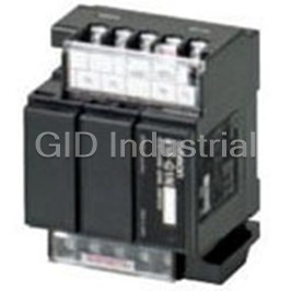
Floatless Level Controller 15-Pin
61F-G2NAC100/200
Part Number
61F-G2NAC100/200
Price
Request Quote
Manufacturer
OMRON AUTOMATION
Lead Time
Request Quote
Category
Semiconductors » Specialized Interfaces
Specifications
Manufacturer
Omron Automation
Manufacturers Part #
61F-G2NAC100/200
Industry Aliases
61F-G2N100/200VAC
Sub-Category
Specialized Semicondutor Interfaces
Factory Pack Quantity
1
Datasheet

Extracted Text
Floatless Level Switch (Compact Type) 61F-G@N CSM_61F-G_N_DS_E_3_3 Improved Design for a More Lightweight Construction and Reduced Standby Power Consumption. • Standby power reduced to 85% or less of previous models. (Applicable to 61F-GN.) Weighs only 85% or less of previous models. (Applicable to 61F-G3N/-G4N.) Easy identification of operating status with LED operation indicator. Increased reliability of internal relay (micro load: 5 VDC, 1 mA) to enable PLC input. Electrode terminals and other wiring terminals are separated for easy wiring. Select from three mounting me thods: JEM, DIN rail mounting, or screw mounting. Note: LED operation indicator is provided on Controllers manufactured in August 1999 or later. Refer to Safety Precautions for Floatless Level Controllers. Model Number Structure ■ Model Number Legend 61F-@N@ 1 2 1. Controller Application 2. Type Position of G: Automatic water supply and Blank: General-purpose LED Indicator drainage L 2KM: Long-distance (for 2 km) G1: Automatic water supply with idling L 4KM: Long-distance (for 4 km) prevention or water shortage alarm H: High-sensitivity G2: Automatic water supply and D: Low-sensitivity drainage with abnormal water R: Two-wire increase alarm Note: LED indicator is provided on G3: Automatic water supply and Controllers manufactured in drainage with full tank and water August 1999 or later. shortage alarm It is not mounted on the case surface. It can be seen G4: Automatic water supply with water through the case. level indicator for water supply tank and water receiving tank and prevention of idling due to water shortage I: Liquid level indication and alarm (no two-wire models) 1 61F-G@N Ordering Information Classification by Set contents General- Long-distance High- Low- Two wire application purpose (between sensitivity (for sensitivity (for Controller and high specific low specific Classification by Electrodes) resistance) resistance) control purpose (See note 2.) Controller GN ◆ 61F-GN Base x 1 61F-GN 61F-GNL 61F-GNH 61F-GND 61F-GNR Models 61F-11@ Units x 1 G1N w/pump idling 61F-G1N Base x 1 61F-G1N 61F-G1NL 61F-G1NH 61F-G1ND 61F-G1NR Models prevention 61F-11@ Units x 2 w/alarm for abnormally low level G2N ◆ w/alarm for 61F-G2N Base x 1 61F-G2N 61F-G2NL 61F-G2NH 61F-G2ND 61F-G2NR Models abnormally high 61F-11@ Units x 2 level G3N ◆ w/alarm for 61F-G3N Base x 1 61F-G3N 61F-G3NL 61F-G3NH 61F-G3ND 61F-G3NR Models abnormally high 61F-11@ Units x 3 and low levels G4N w/level 61F-G4N Base x 1 61F-G4N 61F-G4NL 61F-G4NH 61F-G4ND 61F-G4NR Models display of water 61F-11@ Units x 5 source and tank MY3 Relay x 1 IN Level indication 61F-IN Base x 1 61F-IN 61F-INL 61F-INH 61F-IND 61F-INR Models with alarm 61F-11@ Units x 2 Relay unit 61F-11@ Units x 1 61F-11N 61F-11NL 61F-11NH 61F-11ND 61F-11NR Note: 1. ◆: Automatic water supply and drainage control, : Automatic water supply control 2. Subclassified into 2 km and 4 km models according to the model of relay unit used. Specify 2 km or 4 km when ordering. 3. When ordering, specify the desired operating voltage at the end of the model number. Example: 61F-GN[110/220 VAC] Desired supply voltage 4. Contact your OMRON representative for products with voltages other than those listed above. 5. If you order with a standard model number, the corresponding Relay Units are also delivered as part of a set. If you order the 61F-GN, one 61F-11 Relay Unit is included in the set. 2 61F-G@N Specifications Standard Models Type General-purpose Controllers 61F-@N Long-distance 61F-@NL 2KM (2 km) High-sensitivity Controllers 61F-@NH Controllers 61F-@NL 4KM (4 km) Items Controlling materials and For control of ordinary purified water and For control of ordinary purified water and For control of liquids with high specific operating conditions wastewater wastewater. Particularly in cases where the resistance, such as distilled water distance between the pumps and water tanks or between supply and receiver tanks are far apart or where remote control is required. Rated voltage 100/200, 110/220 or 120/240 VAC, 50/60 Hz (both supported on same model) Allowable voltage 85% to 110% of rated voltage fluctuation range Inter-electrode voltage 8 VAC Inter-electrode current Approx. 1 mA AC max. Power consumption GN@: 3 VA max., G1N@, G2N@, IN@: 4 VA max., G3N@: 5.5 VA max., G4N@: 8.5 VA max. Inter-electrode operation 0 to approx. 4 kΩ 0 to 1.8 kΩ (for 2 km) Approx. 10 kΩ to 40 kΩ (See note 4.) resistance 0 to 0.7 kΩ (for 4 km) (recommended values) Inter-electrode release Approx. 15 k to ∞Ω 4 k to ∞Ω (for 2 km) Approx. 100 k to ∞Ω resistance 2.5 k to ∞Ω (for 4 km) (recommended values) Cable length 1 km max. 2 km max. 50 m max. (See note 2.) 4 km max. Output 3 A, 200 VAC (Resistive load) Ambient operating −10 to 55°C temperature Ambient operating 45% to 85% humidity Insulation resistance 100 MΩ min. (at 500 VDC) (See note 3.) Dielectric strength 2,000 VAC, 50/60 Hz for 1 min. (See note 3.) Life expectancy Electrical: 250,000 operations min. Mechanical: 10,000,000 operations min. Weight GN models: 315 g; G1N, G2N, IN models: 410 g; G3N models: 625g; G4N models: 870 g Internal Circuit Diagrams Example: 61F-GN Example: 61F-GNL Example: 61F-GNH S2 S1 S0 S2 S1 S0 S2 S1 S0 Tb Tc Ta Tb Tc Ta Tb Tc Ta U U U 0 V Transformer 0 V Transformer 0 V Transformer 61F-11N U 61F-11N U 61F-11N U 24 V 24 V 24 V 100 V 100 V 100 V Relay Unit Relay Unit Relay Unit 8 V 8 V 8 V 200 V 200 V 200 V U U U E3 E2 E1 E3 E2 E1 E3 E2 E1 Note: 1. The @ in the model name represents G, G1, G2, G3, G4, or I. 2 2. The length when using completely insulated, 600-V, 3-core (0.75 mm ) cabtire cables. Usable cable lengths will become shorter as the cable diameter or number of cores becomes larger due to increased floating capacity. For details, refer to Safety Precautions for Floatless Level Controllers. 3. The insulation resistance and dielectric strength are the values between power terminals and Electrode terminals, between power terminals and contact terminals, and between Electrode terminals and contact terminals. For details, refer to Safety Precautions for Floatless Level Controllers. 4. Application is possible with 10 kΩ or less, however, this may cause reset failures. 3 61F-G@N Type Low-sensitivity Controller 61F-@ND Two-wire Controller 61F-@NR ■ Relay Unit Items Controlling materials For control of liquids with low specific For control of ordinary purified water The Relay Unit can be replaced without and operating resistance, such as salt water, wastewater, or wastewater. Used with a Two-wire removing the wires for maintenance conditions acid chemicals, or alkaline chemicals Electrode Holder (incorporating a inspections. It can also be replaced with resistor of 6.8 kΩ) other Relay Units. Rated voltage 100/200, 110/220 or 120/240 VAC, 50/60 Hz (supported by the same model) Allowable Voltage 85% to 110% of rated voltage Fluctuation Compatibility with Inter-electrode voltage 8 VAC General Purpose Model Inter-electrode current Approx. 1 mA AC max. Power consumption GN@: 3 VA max., G1N@, G2N@, IN@: 4 VA max., G3N@: 5.5 VA max., (61F-11N) G4N@: 8.5 VA max. Inter-electrode 0 to approx. 1.8 kΩ Approx. 0 to 1.1 kΩ General- 61F-11N --- operation resistance purpose (recommended values) Controller Inter-electrode release Approx. 5 k to ∞ Ω Approx. 15 k to ∞ Ω Long- 61F-11NL (for 2 km) Provided resistance distance 61F-11NL (for 4 km) (recommended values) Controllers Cable length 1 km max. 800 m max. High- 61F-11NH (See note 2.) sensitivity Output 3 A, 200 VAC (Resistive load) Controllers Ambient operating −10 to 55°C Low- 61F-11ND temperature sensitivity Controller Ambient operating 45% to 85% humidity Two-wire 61F-11NR Not Controller provided Insulation resistance 100 MΩ min. (at 500 VDC) (See note 3.) Dielectric strength 2,000 VAC, 50/60 Hz for 1 min. Terminal Arrangement (See note 3.) ES S S Life expectancy Electrical: 250,000 operations min. Mechanical: 10,000,000 operations min. 10 9 8 7 11 8 V 24 V 24 V Weight GN models: 315 g; G1N, G2N, IN models: 410 g; G3N models: 625g; G4N models: 870 g Relay Unit Circuit Internal Circuit Example: 61F-GND Example: 61F-GNR Diagrams S2 S1 S0 S2 S1 S0 Tb Ta Tb Ta Tc Tc U U 0 V Transformer 0V Transformer 45 6 1 2 3 U U 61F-11ND 61F-11ND Tb1 Ta1 Tc1 Tc2 Ta2 Tb2 24 V 24V 100 V 100V Relay Unit Relay Unit 8 V 8V 200 V 200V U U Ordering Example E3 E2 E1 E3 E1 If you order the components listed above, the corresponding Relay Unit Note: 1. The @ in the model name represents G, G1, G2, G3, G4, or I. will be supplied with the Controller. 2 2. The length when using completely insulated, 600-V, 3-core (0.75 mm ) cabtire cables. Example: If a 61F-GN Controller is Usable cable lengths will become shorter as the cable diameter or number of cores ordered, a 61F-11N Relay becomes larger due to increased floating capacity. For details, refer to Safety Precautions for Floatless Level Controllers. Unit will also be included. 3. The insulation resistance and dielectric strength are the values between power terminals and Electrode terminals, between power terminals and contact terminals, and between Electrode terminals and contact terminals. For details, refer to Safety Precautions for Floatless Level Controllers. 4. Application is possible with 10 kΩ or less, however, this may cause reset failures. 4 61F-G@N ■ Connections Automatic Water Supply Control Compact Model 61F-GN Dimensions page 16 Automatic Water Supply Control Connections • Connect contactor coil terminal to Tb. Connect to power supply terminals. S0-S1: 110 VAC S0-S2: 220 VAC 220-VAC power supply RS T 61F-GN MCCB Ta E1 0 V 24 V S0 61F-11N U U Relay Unit Tc 110 V E2 S1 U Tb 8 V 220 V E3 S2 Transformer (See note 1.) Contactor PS-3S Motor protection Stop E1 Water relay tank Start Water supply E2 E3 source MP Note: 1. Be sure to ground the common Electrode E3 (the longest Electrode). 2. The above wiring diagram is for a rated voltage of 110/220 VAC. Principles of Operation The pump stops (U indicator ON) Relay Unit Layout when the water level reaches E and 1 starts (U indicator OFF) when the water level drops below E2. U Water supply 1 P (U indicator ON) Pump OFF E1 Pump ON (U indicator OFF) E2 E3 5 Power supply 61F-G@N Automatic Drainage Control Compact Model 61F-GN Dimensions page 16 Automatic Drainage Control Connections Connect the contactor coil terminal to Ta. Connect to power supply terminals. S -S : 110 VAC 0 1 S -S : 220 VAC 0 2 220-VAC power supply RS T 61F-GN MCCB Ta E1 0 V 24 V S0 U 61F-11N U Relay Unit Tc 110 V E2 S1 U Tb 8 V 220 V E3 S2 Transformer Contactor (See note 1.) Motor protection PS-3S relay Start E1 Wastewater Stop tank E2 E3 MP Reservoir Note: 1. Be sure to ground the common Electrode E3 (the longest Electrode). 2. The above wiring diagram is for a rated voltage of 110/220 VAC. Principles of Operation The pump starts (U indicator ON) Relay Unit Layout when the water level reaches E 1 and stops (U indicator OFF) when the water level drops below E . 2 U 1 (U indicator ON) Pump ON E1 Pump OFF (U indicator OFF) E2 E3 P Water drainage 6 Power supply 61F-G@N Automatic Water Supply Control with Compact Model 61F-G1N Pump Idling Prevention Dimensions page 16 Automatic Water Supply Control with Pump Idling Prevention Connections Connect to power supply terminals. 220-VAC power supply S -S : 110 VAC 0 1 RS T S -S : 220 VAC 0 2 Insert a pushbutton switch (NO contact) between E ' and 1 MCCB E as shown by the dotted 3 61F-G1N line. Do not press the pushbutton U1 switch if the pump stops (U Tc2 E1 1 0 V 61F-11N U1 indicator OFF) during normal S0 24 V U2 Relay Unit operation after an alarm is B Tb2 E2 110 V U2 61F-11N given for a low water level S1 24 V Alarm Bell Relay Unit (e.g., the water level does not E3 220 V reach E2'). 8 V S2 Ta1 U2 Test Operation/ Transformer E1' Recovering from U1 Tb1 Power Interruptions E2' If the water supply source level has not yet reached E1' when starting the pump or after recovering from a power interruption, press the Contactor pushbutton switch to start the (See note 1.) pump (U1 indicator ON) by PS-3S momentarily short-circuiting E1' and E3. Stop Motor E1 Water PS-3S Protection tank Start E2 Relay E3 Water E1' supply Water source E2' shortage E3 M P Note: 1. Be sure to ground the common Electrode E3 (the longest Electrode). 2. The above wiring diagram is for a rated voltage of 110/220 VAC. Water supply source Principles of Operation Note The pump starts (U2 indicator Relay Unit Layout • Length of Electrode E1' OFF) when the water level When installing the Controller in drops below E2 and stops (U2 Water (U1 indicator ON) indicator ON) when water level E1' locations where there is a possibility of shortage (U1 indicator OFF) U U reaches E1. E2' momentary power interrupts or blackouts, 2 1 The pump is forced to stop the length of E1' should be made so that E3 when the water supply source the amount of water corresponding to level drops below E2' (U1 one pump cycle does not expose the BL indicator OFF) to prevent the Electrodes. This will prevent the E2' Water tank pump from idling and gives an self-holding circuit from failing. Water supply alarm. P Water supply source Float (U2 indicator ON) Pump OFF E1 Amount of water for one pump cycle E1' E2' Pump ON (U2 indicator OFF) E3 E2 E3 7 Power supply (Pushbutton switch) 61F-G@N Automatic Water Supply Control with Compact Model Abnormal Water Shortage Alarm 61F-G1N Dimensions page 16 Automatic Water Supply Control with Abnormal Water Shortage Alarm Connections Connect to power supply terminals. S -S : 110 VAC 0 1 220-VAC power supply S -S : 220 VAC RS T 0 2 Insert a pushbutton switch (NO contact) between E 3 MCCB and E . 4 61F-G1N If the pump stops upon releasing the pushbutton U1 switch, keep pressing the E1 Tc2 pushbutton switch. 0 V U1 61F-11N S0 24 V U2 Relay Unit Connect the E electrode for 4 B Tb2 E2 the water shortage alarm to 110 V U2 61F-11N S1 24 V Alarm Bell Relay Unit the E ’ terminal. 1 E3 220 V 8 V S2 Test Operation/ Ta1 Transformer Recovering from U2 E1' Power Interruptions U1 (E4) Tb1 If the water level has not yet E2' reached E4 when starting the pump or after recovering from a power interruption, press Contactor the pushbutton switch to start (See note 1.) the pump by short-circuiting PS-4S E3 and E4 (U1 indicator ON). Stop Motor E1 Water Protection Start tank E2 Water Relay E4 shortage Water supply E3 source M P Note: 1. Be sure to ground the common Electrode E (the longest Electrode). 3 2. The above wiring diagram is for a rated voltage of 110/220 VAC. Principles of Operation The pump stops (U2 indicator Relay Unit Layout ON) when the water level reaches E1 and starts (U2 Water supply source indicator OFF) when water level U U Water supply drops below E2. 2 1 P If the water level drops below E4 (U2 indicator ON) Pump OFF E1 for any reason, an alarm is given 1 (U indicator OFF). Pump ON (U2 indicator OFF) E2 Water shortage (U1 indicator OFF) E4 BL E3 8 Power supply (Pushbutton switch) 61F-G@N Automatic Water Supply with Compact Model 61F-G2N Abnormal Water Increase Alarm Dimensions page 16 Automatic Water Supply with Abnormal Water Increase Alarm Connections Connect power supply terminal S to terminal Tb . 2 1 Connect to power supply 220-VAC power supply terminals. RS T S -S : 110 VAC 0 1 S -S : 220 VAC 0 2 61F-G2N MCCB E1 Ta2 0 V U1 61F-11N S0 24 V U2 U1 Relay Unit Tc2 B E2 110 V U2 61F-11N S1 24 V Alarm Bell Relay Unit Ta1 E3 220 V 8 V S2 U2 Tc1 Transformer E4 Tb1 (See note 1.) Contactor PS-4S Motor Full tank Water E4 Protection Stop tank E1 Relay Start Water supply E2 source E3 M P Reservoir Note: 1. Be sure to ground the common Electrode E3 (the longest Electrode). 2. The above wiring diagram is for a rated voltage of 110/220 VAC. Principles of Operation The pump starts (U indicator OFF) 2 Relay Unit Layout when the water level reaches E and 2 stops (U indicator ON) when the 2 water level rises above E . 1 U U Water supply B L 2 1 P If the water level reaches E for any 4 Upper limit reason, an alarm is given (U (U1 indicator ON) 1 E4 indicator ON). (U2 indicator ON) Pump OFF E1 Pump ON (U2 indicator OFF) E2 E3 9 Power supply 61F-G@N Automatic Drainage Control with Compact Model 61F-G2N Abnormal Water Increase Alarm Dimensions page 16 Automatic Drainage Control with Abnormal Water Increase Alarm Connections Connect power supply S to 2 terminal Ta . 220-VAC power supply 1 RS T Connect to power supply terminals. S -S : 110 VAC 0 1 61F-G2N S -S : 220 VAC MCCB 0 2 E1 Ta2 0 V U1 61F-11N S0 24 V U2 U1 Relay Unit B Tc2 E2 110 V U2 61F-11N S1 24 V Alarm Bell Relay Unit Ta1 E3 220 V 8 V S2 U2 Tc1 Transformer E4 Tb1 (See note 1.) Contactor Motor Protection PS-4S Relay Wastewater tank Full tank E4 Start E1 Stop E2 E3 M P Reservoir Note: 1. Be sure to ground the common Electrode E5 (the longest Electrode). 2. The above wiring diagram is for a rated voltage of 110/220 VAC. Principles of Operation The pump starts (U indicator ON) 2 Relay Unit Layout Water tank when the water level reaches E and 1 stops (U indicator OFF) when the 2 water level drops below E . 2 U U Upper limit B L 2 1 (U1 indicator ON) If the water level reaches E for any 4 E4 reason, an alarm is given (U 1 (U2 indicator ON) indicator ON). Pump ON E1 Pump OFF (U2 indicator OFF) E2 E3 P Water drainage 10 Power supply 61F-G@N Automatic Water Supply Control with Compact Model 61F-G3N Full Tank and Water Shortage Alarm Dimensions page 17 Automatic Water Supply Control with Full Tank and Water Shortage Alarm Connections Connect contactor coil terminal to Tb. Connect to power supply terminals. S -S : 110 VAC 0 1 S -S : 220 VAC 0 2 220-VAC power supply 61F-G3N RS T Transformer Ta 0 V S0 24 V U2 MCCB To 61F-11N Tc Relay Unit 110 V S1 24 V E1 Tb 220 V 8 V S2 E2 U2 U1 E3 Upper limit U1 U3 61F-11N Relay Unit PL LH E4 B1 U2 61F-11N U1 Relay Unit Lc E5 Lower limit B2 U3 U3 61F-11N PL LL Relay Unit (See note 1.) B Alarm Bell Contactor PS-5S Full tank Motor E1 Water Stop E2 Protection tank Start E3 Relay Water shortage Water supply E4 E5 source M P Note: 1. Be sure to ground the common Electrode E5 (the longest Electrode). 2. The above wiring diagram is for a rated voltage of 110/220 VAC. Principles of Operation The pump starts (U indicator ON) 2 Relay Unit Layout when the water level reaches E and 2 stops (U indicator OFF) when the 2 water level drops below E . Water supply LH B 3 U U U P Upper limit 3 2 1 If the water level rises to E for any 1 (U1 indicator ON) reason, the upper-limit indicator turns E1 ON and an alarm is given (U indicator 1 (U2 indicator ON) Pump OFF ON). If the water level drops below E 4 E2 for any reason, the lower-limit indicator turns ON and an alarm is given (U 3 Pump ON indicator OFF). (U2 indicator OFF) E3 (U3 indicator OFF) Lower E4 limit E5 LL B 11 Power supply 61F-G@N Compact Model Automatic Drainage Control with 61F-G3N Full Tank and Water Shortage Alarm Dimensions page 17 Automatic Drainage Control with Full Tank and Water Shortage Alarm Connections Connect contactor coil terminal to Ta. Connect to power supply terminals. S -S : 110 VAC 0 1 S -S : 220 VAC 0 2 220-VAC power supply 61F-G3N RS T Transformer Ta 0 V S0 24 V U2 MCCB To 61F-11N Tc Relay Unit 110 V S1 24 V E1 Tb 220 V 8 V S2 E2 U2 U1 E3 Upper limit U1 U3 61F-11N Relay Unit PL LH E4 B1 U2 61F-11N U1 Relay Unit LC E5 Lower limit B2 U3 U3 61F-11N PL LL Relay Unit B Alarm Bell Contactor (See note 1.) Motor PS-5S Protection Relay Full tank E1 Start E2 Wastewater Stop tank E3 Water shortage E4 E5 M P Reservoir Note: 1. Be sure to ground the common Electrode E5 (the longest Electrode). 2. The above wiring diagram is for a rated voltage of 110/220 VAC. Principles of Operation The pump starts (U indicator ON) 2 Relay Unit Layout when the water level reaches E and 2 stops (U indicator OFF) when the 2 water level reaches E . LH B 3 U U U Upper limit 3 2 1 If the water level rises to E for any 1 (U1 indicator ON) reason, the upper-limit indicator turns E1 ON and an alarm is given (U1 indicator (U2 indicator ON) Pump ON ON). If the water level drops below E4 E2 for any reason, the lower-limit indicator turns ON and an alarm is given (U3 Pump OFF indicator OFF). (U2 indicator OFF) E3 (U3 indicator OFF) Lower E4 limit E5 LL B 12 Power supply 61F-G@N Water Source Level Indication with Compact Model Prevention of Pump Idling Due to Water 61F-G4N Shortage, and Automatic Water Supply Control with Indication of Water Level in Dimensions Elevated Tank page 17 Water Source Level Indication with Prevention of Pump Idling Due to Water Shortage, and Automatic Water Supply Control with Indication of Water Level in Elevated Tank Connections 220-VAC power supply 61F-G4N RS T Transformer Connect to power supply S0 0 V terminals. 24 V X To 61F-11N S0-S1: 110 VAC U2 MCCB S1 MY3 Relay Relay Unit S0-S2: 220 VAC 24 V 110 V S2 Insert a pushbutton switch X (NO contact) between E2 8 V Tc 220 V and E8 as shown by the E1 U5 dotted line. Tc2 E2 Do not press the TA U2 pushbutton switch if the E3 pump stops during normal operation after an alarm is E8 given for low water level B E4 (i.e., the water level has not U4 BH1 BH1 Elevated reached E3). U3 61F-11N tank repletion E5 U1 Relay Unit BL1 BL1 Elevated Test Operation/ tank water U2 E6 61F-11N U3 shortage Recovering from Relay Unit BH2 BH2 Water supply source upper Power Interruptions E7 X U4 limit 61F-11N BL2 Water supply BL2 Relay Unit When starting the pump and source lower E8 U4 limit U5 after recovering from a power LH1 61F-11N LH1 Elevated tank repletion Relay Unit interruption, if the water U1 U5 LL1 LL1 Elevated U1 source level has not yet 61F-11N tank water Relay Unit U3 shortage reached E2 (U2 indicator LH2 LH2 Water supply OFF), press the pushbutton source upper limit X switch to start the pump by LL2 LL2 Water supply Contactor source lower momentarily short-circuiting limit E2 and E8. (See note 1.) PS-5S Motor Protection Relay Full tank E4 Stop PS-4S Water E5 Start tank E6 Upper limit Water Water E7 E1 shortage supply ON E8 source E2 OFF E3 Lower limit E8 M P Note: 1. Be sure to ground the common Electrode E8 (the longest Electrode). 2. The above wiring diagram is for a rated voltage of 110/220 VAC. Principles of Operation Relay Unit Layout Precaution Insert four Electrodes in the water supply source and five • Length of Electrode E2 Electrodes in the elevated water tank. When installing the Controller in locations U U U U U The lower-limit indicator for the water supply source remains X 5 4 3 2 1 where there is a possibility of momentary ON while the water source level is below E (U indicator 3 2 power interruptions or blackouts, the OFF). length of E2 should be made so that the When the water level rises to E2, the lower-limit indicator turns OFF (U2 indicator amount of water corresponding to one ON) and the pump is ready for operation. pump cycle does not expose the Electrodes. This will prevent the E3 When the water level reaches E1, the upper-limit indicator turns ON (U3 indicator self-holding circuit from failing. ON). The water-shortage indicator for the elevated tank remains ON while the water level Water supply source in the elevated tank is below E7. The indicator turns OFF (U1 indicator ON) when the Float water level rises to E7. The pump stops (U5 indicator ON) when the water level reaches E and starts (U5 E1 5 Float valve open Amount of water for indicator OFF) when the water level drops below E . 6 E2 one pump cycle If the water level reaches E4 for any reason, the tank repletion indicator for the E3 E8 elevated tank turns ON (U4 indicator ON). 13 Power supply (Pushbutton switch) 61F-G@N Liquid Level Indication and Alarm Compact Model 61F-IN Dimensions page 16 Liquid Level Indication and Alarm Connections 220-VAC power supply RS T Connect to power supply terminals. S0-S1: 110 VAC S0-S2: 220 VAC MCCB 61F-IN E1 Tc U2 0 V U1 61F-11N S0 24 V Relay Unit B B E2 Alarm Bell 110 V 61F-11N U2 S1 24 V Relay Unit PL L1 U2 Lower limit E3 220 V 8 V S2 Transformer PL L2 Upper limit U1 L3 PL U1 Intermediate (See note 1.) PS-3S Upper limit E1 Water Intermediate tank E2 Lower limit E3 Water supply source M P Note: 1. Be sure to ground the common Electrode E3 (the longest Electrode). 2. The above wiring diagram is for a rated voltage of 110/220 VAC. Principles of Operation When the water level drops below E2, the Relay Unit Layout Water tank lower-limit indicator turns ON and an alarm is given (U2 indicator OFF). Upper B LH (U1 indicator ON) When the water level reaches E2, the alarm limit U U 2 1 E1 turns OFF and the intermediate indicator turns (U1 indicator OFF) ON (U2 indicator ON). Interme- LM diate When the water level rises to E1, the upper- (U2 indicator ON) limit indicator turns ON and an alarm is given Lower E2 (U2 indicator OFF) 1 indicator ON). (U limit B LL E3 14 Power supply 61F-G@N ■ Two-wire Connection The wiring between the 61F Controller and the Electrodes can be reduced by removing the self-hold circuit. This arrangement is called a two-wire connection. Three Electrodes are still required. Both the 61F Controller (including the Relay Unit) and Electrode Holder must be two-wire models. Two-wire Electrode Holders have an in-built resistor of 6.8 kΩ 1W. Automatic Water Supply and Compact Model 61F-GNR Drainage Control Dimensions page 16 Automatic Water Supply Control Automatic Drainage Control Connections Connections 220-VAC power supply 220-VAC power supply RS T RS T 61F-GNR 61F-GNR MCCB MCCB Ta Ta 0 V 24V E1 0 V 24 V E1 S0 61F-11NR U S0 61F-11NR U U U Relay Unit Relay Unit Tc Tc 110 V 110 V U S1 U S1 Tb Tb 8 V 8 V 220 V 220 V E3 S2 E3 S2 Transformer Transformer (See note 1.) Contactor Contactor (See note 1.) PS-3SR R Motor Motor Stop protection E1 protection PS-3SR Water R relay relay tank Wastewater Water E2 Start E3 tank Start supply E1 Stop source E2 E3 MP MP Reservoir Note: 1. Be sure to ground the common Electrode E3 (the longest Note: 1. Be sure to ground the common Electrode E3 (the Electrode). longest Electrode). 2. The above wiring diagram is for a rated voltage of 110/ 2. The above wiring diagram is for a rated voltage of 110/ 220 VAC. 220 VAC. • Connect contactor coil terminal to Tb.Connect contactor coil terminal to Ta. (Do not connect Tb.) Connect to power supply terminals.Connect to power supply terminals. S0-S1: 100 VAC S0-S1: 100 VAC S0-S2: 200 VAC S0-S2: 200 VAC The two-wire models require only two cables for the connection The two-wire models require only two cables for the connection between the 61F-GNR and the Electrode Holder, but still between 61F-GNR and the Electrode Holder, but still needs requires three Electrodes. three Electrodes. A Two-wire Electrode Holder must be used. (It has an inbuilt A Two-wire Electrode Holder must be used. (It has an inbuilt resistance R.) resistance R.) The Relay Unit must also be for two-wire models.The Relay Unit must also be for two-wire models. Principles of Operation Principles of Operation Water supply P (U indicator ON) Pump ON E1 (U indicator ON) Pump OFF E1 Pump OFF (U indicator OFF) E2 Pump ON (U indicator OFF) E2 E3 P E3 Water Drainage The pump stops (U indicator ON) when the water level reaches The pump starts (U indicator ON) when the water level reaches E1 E1 and starts (U indicator OFF) when water level drops below E2. and stops (U indicator OFF) when the water level drops below E2. 15 61F-G@N Dimensions Note: All units are in millimeters unless otherwise indicated. 61F-GN, -GNL, -GNH, -GND, -GNR 25 5 14 14 32 3 60 11 5 65 54 Terminal cover 11 10 9 Nine, M3.5 sems screws 3.4 4 min. 5 10 100 70 56 50 35.4 90 4 min. 40 39 4 (See note.) 50 43.5 Note: Dimensions are with the DIN rail mounting (sliding) bracket attached. 61F-G1N, -G1NL, -G1NH, -G1ND, -G1NR 61F-G2N, -G2NL, -G2NH, -G2ND, G2NR 25 61F-IN, - NL, -INH, -IND 5 14 14 32 3 60 11 5 65 54 Terminal cover 11 10 9 Fifteen, M3.5 sems screws 3.4 4 min. 5 10 100 70 56 50 35.4 90 4 min. 65 39 4 (See note.) 75 43.5 Note: Dimensions are with the DIN rail mounting (sliding) bracket attached. 16 61F-G@N 61F-G3N, -G3NL, -G3NH, -G3ND, -G3NR, -G3N-NGD 25 5 14 14 32 3 60 11 5 65 54 Terminal cover 11 10 3.4 9 21, M3.5 sems screws Min. 4 5 10 100 70 56 50 35.4 90 Min. 4 115 39 4 (See note.) 125 43.5 Note: Dimensions are with the DIN rail mounting (sliding) bracket attached. 61F-G4N, - G4NL, -G4NH, -G4ND, -G4NR, -G4N-KYD 25 5 14 14 32 3 60 5 65 Terminal cover 11 10 25, M3.5 sems screws 9 3.4 Min. 4 5 10 100 70 56 50 35.4 90 Min. 4 190 39 4 (See note.) 200 43.5 Note: Dimensions are with the DIN rail mounting (sliding) bracket attached. ■ Safety Precautions Refer to Safety Precautions for All Level Controllers. ALL DIMENSIONS SHOWN ARE IN MILLIMETERS. To convert millimeters into inches, multiply by 0.03937. To convert grams into ounces, multiply by 0.03527. In the interest of product improvement, specifications are subject to change without notice. 17 Terms and Conditions Agreement Read and understand this catalog. Please read and understand this catalog before purchasing the products. Please consult your OMRON representative if you have any questions or comments. Warranties. (a) Exclusive Warranty. Omron’s exclusive warranty is that the Products will be free from defects in materials and workmanship for a period of twelve months from the date of sale by Omron (or such other period expressed in writing by Omron). Omron disclaims all other warranties, express or implied. (b) Limitations. OMRON MAKES NO WARRANTY OR REPRESENTATION, EXPRESS OR IMPLIED, ABOUT NON-INFRINGEMENT, MERCHANTABILITY OR FITNESS FOR A PARTICULAR PURPOSE OF THE PRODUCTS. BUYER ACKNOWLEDGES THAT IT ALONE HAS DETERMINED THAT THE PRODUCTS WILL SUITABLY MEET THE REQUIREMENTS OF THEIR INTENDED USE. Omron further disclaims all warranties and responsibility of any type for claims or expenses based on infringement by the Products or otherwise of any intellectual property right. (c) Buyer Remedy. Omron’s sole obligation hereunder shall be, at Omron’s election, to (i) replace (in the form originally shipped with Buyer responsible for labor charges for removal or replacement thereof) the non-complying Product, (ii) repair the non-complying Product, or (iii) repay or credit Buyer an amount equal to the purchase price of the non-complying Product; provided that in no event shall Omron be responsible for warranty, repair, indemnity or any other claims or expenses regarding the Products unless Omron’s analysis confirms that the Products were properly handled, stored, installed and maintained and not subject to contamination, abuse, misuse or inappropriate modification. Return of any Products by Buyer must be approved in writing by Omron before shipment. Omron Companies shall not be liable for the suitability or unsuitability or the results from the use of Products in combination with any electrical or electronic components, circuits, system assemblies or any other materials or substances or environments. Any advice, recommendations or information given orally or in writing, are not to be construed as an amendment or addition to the above warranty. See http://www.omron.com/global/ or contact your Omron representative for published information. Limitation on Liability; Etc. OMRON COMPANIES SHALL NOT BE LIABLE FOR SPECIAL, INDIRECT, INCIDENTAL, OR CONSEQUENTIAL DAMAGES, LOSS OF PROFITS OR PRODUCTION OR COMMERCIAL LOSS IN ANY WAY CONNECTED WITH THE PRODUCTS, WHETHER SUCH CLAIM IS BASED IN CONTRACT, WARRANTY, NEGLIGENCE OR STRICT LIABILITY. Further, in no event shall liability of Omron Companies exceed the individual price of the Product on which liability is asserted. Suitability of Use. Omron Companies shall not be responsible for conformity with any standards, codes or regulations which apply to the combination of the Product in the Buyer’s application or use of the Product. At Buyer’s request, Omron will provide applicable third party certification documents identifying ratings and limitations of use which apply to the Product. This information by itself is not sufficient for a complete determination of the suitability of the Product in combination with the end product, machine, system, or other application or use. Buyer shall be solely responsible for determining appropriateness of the particular Product with respect to Buyer’s application, product or system. Buyer shall take application responsibility in all cases. NEVER USE THE PRODUCT FOR AN APPLICATION INVOLVING SERIOUS RISK TO LIFE OR PROPERTY OR IN LARGE QUANTITIES WITHOUT ENSURING THAT THE SYSTEM AS A WHOLE HAS BEEN DESIGNED TO ADDRESS THE RISKS, AND THAT THE OMRON PRODUCT(S) IS PROPERLY RATED AND INSTALLED FOR THE INTENDED USE WITHIN THE OVERALL EQUIPMENT OR SYSTEM. Programmable Products. Omron Companies shall not be responsible for the user’s programming of a programmable Product, or any consequence thereof. Performance Data. Data presented in Omron Company websites, catalogs and other materials is provided as a guide for the user in determining suitability and does not constitute a warranty. It may represent the result of Omron’s test conditions, and the user must correlate it to actual application requirements. Actual performance is subject to the Omron’s Warranty and Limitations of Liability. Change in Specifications. Product specifications and accessories may be changed at any time based on improvements and other reasons. It is our practice to change part numbers when published ratings or features are changed, or when significant construction changes are made. However, some specifications of the Product may be changed without any notice. When in doubt, special part numbers may be assigned to fix or establish key specifications for your application. Please consult with your Omron’s representative at any time to confirm actual specifications of purchased Product. Errors and Omissions. Information presented by Omron Companies has been checked and is believed to be accurate; however, no responsibility is assumed for clerical, typographical or proofreading errors or omissions. 2015.11 In the interest of product improvement, specifications are subject to change without notice. OMRON Corporation Industrial Automation Company http://www.ia.omron.com/ (c)Copyright OMRON Corporation 2015 All Right Reserved.
Frequently asked questions
How does Electronics Finder differ from its competitors?

Is there a warranty for the 61F-G2NAC100/200?
Which carrier will Electronics Finder use to ship my parts?
Can I buy parts from Electronics Finder if I am outside the USA?
Which payment methods does Electronics Finder accept?
Why buy from GID?

Quality
We are industry veterans who take pride in our work

Protection
Avoid the dangers of risky trading in the gray market

Access
Our network of suppliers is ready and at your disposal

Savings
Maintain legacy systems to prevent costly downtime

Speed
Time is of the essence, and we are respectful of yours
Related Products
Floatless Level Controller 11-Pin 61F-11
Floatless Level Controller 11-Pin 61F-11N
Floatless Level Controller 11-Pin 61F-11ND
Floatless Level Controller 11-Pin 61F-11NH
Floatless Level Controller 11-Pin 61F-11NR
Floatless Level Controller 15-Pin 61F-1PAC110
Request a Quote

The quote request has been received
Close

Facing challenges or have inquiries? Feel free to contact us!
Call Us +1-469-283-2440
What they say about us
FANTASTIC RESOURCE
One of our top priorities is maintaining our business with precision, and we are constantly looking for affiliates that can help us achieve our goal. With the aid of GID Industrial, our obsolete product management has never been more efficient. They have been a great resource to our company, and have quickly become a go-to supplier on our list!
Bucher Emhart Glass
EXCELLENT SERVICE
With our strict fundamentals and high expectations, we were surprised when we came across GID Industrial and their competitive pricing. When we approached them with our issue, they were incredibly confident in being able to provide us with a seamless solution at the best price for us. GID Industrial quickly understood our needs and provided us with excellent service, as well as fully tested product to ensure what we received would be the right fit for our company.
Fuji
HARD TO FIND A BETTER PROVIDER
Our company provides services to aid in the manufacture of technological products, such as semiconductors and flat panel displays, and often searching for distributors of obsolete product we require can waste time and money. Finding GID Industrial proved to be a great asset to our company, with cost effective solutions and superior knowledge on all of their materials, it’d be hard to find a better provider of obsolete or hard to find products.
Applied Materials
CONSISTENTLY DELIVERS QUALITY SOLUTIONS
Over the years, the equipment used in our company becomes discontinued, but they’re still of great use to us and our customers. Once these products are no longer available through the manufacturer, finding a reliable, quick supplier is a necessity, and luckily for us, GID Industrial has provided the most trustworthy, quality solutions to our obsolete component needs.
Nidec Vamco
TERRIFIC RESOURCE
This company has been a terrific help to us (I work for Trican Well Service) in sourcing the Micron Ram Memory we needed for our Siemens computers. Great service! And great pricing! I know when the product is shipping and when it will arrive, all the way through the ordering process.
Trican Well Service
GO TO SOURCE
When I can't find an obsolete part, I first call GID and they'll come up with my parts every time. Great customer service and follow up as well. Scott emails me from time to time to touch base and see if we're having trouble finding something.....which is often with our 25 yr old equipment.
ConAgra Foods