

 Manufacturers
OMRON AUTOMATION 61F-GP-N2220VAC
Description
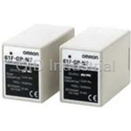
Conductive Level Controller
61F-GP-N2220VAC
Part Number
61F-GP-N2220VAC
Price
Request Quote
Manufacturer
OMRON AUTOMATION
Lead Time
Request Quote
Category
Thermal Management » Misc Products
Specifications
Manufacturer
Omron Automation
Manufacturers Part #
61F-GP-N2220VAC
Lead Time
4 Week Lead Time
Industry Aliases
61F-GP-N2220VAC
Sub-Categories
Miscellaneous Tools and Supplies
Factory Pack Quantity
1
Datasheet

Extracted Text
220 VAC 220 VAC Conductive Level Controller 61F-GP-N2 CSM_61F-GP-N2_DS_E_1_4 Automatic Water Supply and Drainage Control • Ideal for level control of any conductive liquid. • Compact plug-in controller for single- or two-point control of 2 2 conductive liquid level. • 24/110/120/220/230/240 VAC operation possible. • Easy installation on DIN rail. • Low voltage (AC) electrodes. • Full surge protection. Ordering Information Compact plug-in conductive level controller 61F-GP-N2 When placing your order, be sure to specify the desired operating voltage. Example: 61F-GP-N2 120 VAC Rated supply voltage ■ Accessories (Order Separately) Selection Guide for Electrode Holders and Separators Electrode Holders Applications For city water and other When mounting space is For low specific liquids. Used for sewage, When resistance to high general-use elec- limited. Special 3-pole sea water, etc., having a low specific resis- pressure is required. Ide- trodes. Easy-to-replace holder of small size and tance. In sewage use, electrode holders al for use in tanks where separate versions facili- light weight. Ideal for soft must be installed 10 to 20 cm apart from temperature or pressure tate maintenance of drink vendors, etc., where one another. For acids, alkalis and sea wa- inside the tank is high, electrodes. only limited space is avail- ter, electrode holders may be as much as e.g. 250°C able. 1 meter apart to operate properly. Mounting style Flange Screw Flange Screw Insulator material Phenol resin Phenol resin Ceramics Fluorine Resin Max. temperature 70°C (without water drips 150°C (without water drips or vapour on 250°C (without water or vapour on the surface of the surface of the electrode holder) drips or vapour on the the electrode holder) surface of the electrode holder) No. of elec- 1 --- --- BF-1 BS-1 trodes 3 PS-3S PS-31 --- --- Electrode Separators No. of electrodes Model 1 F03-14-1P 3 F03-14-3P 1 61F-GP-N2 Selection Guide for Electrodes, Connecting and Lock Nuts Applicable liquids Material Models for individual electrode assembly components Electrode (1m long) Connecting nut Lock nut Model Indication Model Inscription Model Inscription mark Purified city water, SUS-304 F03-01-SUS304 1 line F03-02-SUS304 --- F03-03-SUS304 --- industrial water, (AISI-304) sewage Purified city water, SUS316 F03-01-SUS316 2 lines F03-02-SUS316 6 F03-03-SUS316 6 industrial water, (AISI-316) sewage, dilute alka- line solution Application Example • Level control in tanks, reservoirs, sewage plants, underground • Dispensing of liquids by volume. wells, mixing plants etc. • Indication of liquid buildup due to filter blockages. • Level control for element protection in pipes, channels, and irriga- • Pollution/foul water detection for rivers, drains, etc. tion systems. • Alarm control warning of abnormal or dangerously high or low lev- • Flow detection in pipes, channels, and irrigation systems. els. • Ice bank control in cold drink dispensers, ice makers, water chillers, bulk milk tanks, etc. Specifications Supply voltage 24, 110, 120, 220, 230, 240 VAC; 50/60 Hz Operating voltage range 85% to 110% of rated voltage * 8 VAC Interelectrode voltage Power consumption Approx. 3.2 VA Operate resistance Approx. 4 KΩ min. Between electrode E1 and E3 Release resistance Approx. 15 KΩ max. Between electrode E2 and E3 Response time Operate: 80 ms max., Release: 160 ms max. Control output 10 A, 250 VAC (at 40°C) 3 A, 250 VAC (at 55°C) Insulation resistance 100 MΩ max. (at 500 VDC) between power terminals and electrode terminals, and between electrode terminals and contact terminals Dielectric strength 2,000 VAC, 50/60 Hz for 1 min., between power terminals and electrode terminals, and between elec- trode terminals and contact terminals Ambient temperature Operating: –10°C to 55°C Ambient humidity Operating: 45% to 85% Life expectancy Mechanical: 10,000,000 operations min. Weight Approx. 190 g Approved standards UL508, CSA C22.2 No.14, EN61010-1, EN61326-1 Industrial electromagnetic environment *Secondary voltage of transformer 2 61F-GP-N2 Connections Automatic Water Supply and Drainage Control 1. Water supply 2. Drainage Connect electromagnetic switch coil terminal A to Tb. Connect the electromagnetic switch coil terminal A to Ta. The pump stops when the water level reaches E1 and starts when The pump starts when the water level reaches E1 and stops when the water level drops below E2. the water level drops below E2. Note: 1. The diagram shows the connections for water supply. When draining, change the connection Tb to Ta. 2. The earth terminal must be grounded. Power source RS T 220 or 240 VAC 5 4 MCCB Tc S2 3 6 Ta S1 E1 Tb 2 7 E3 E2 8 1 Earth A Electromagnetic switch E1 Stop Tank M P Start E2 E3 Reservoir Operation The conductive type level controller consists of a plug-in controller For two-point control a low-level probe is used as well. In this case connected to a set of stainless steel probes. These are cut to length the relay does not de-energize until the water level falls below the and inserted vertically into the liquid. A low voltage is applied low-level probe. Using the low-level probe allows a wide differential between these probes and the earth probe (or tank, if it is electrically between switching a pump on and off, and can avoid excessive pump conductive). The water provides a current between the earth probe operation during tank emptying or filling. If this differential is not and the high-level probe. The output relay in the controller is ener- required, the low-level probe need not be connected. gized when the water level reaches the high-level probe and de-ener- gized when the water level falls below it. Dimensions Note: All units are in millimeters unless otherwise indicated. 61F- GP-N2 49.4 91 38 70 38 70 84 80 PF083A 3 61F-GP-N2 ■ Electrode Holders PS-3S PF2 parallel thread (effective dia.: 58.135) PS-3S/-3SR PS-4S/-4SR PS-5S/-5SR 9-dia. rubber bushing (inner) 34 dia. E2 E3 E2 E3 E2 80 92 E1 E1 E1 E4 E4 E3 26 80 13 40 20 Mounting Holes Screw Holes Used with coupling Used with mounting bracket PF2 65 dia. hole PS-31 PF1/2 Parallel thread 38.5 11-dia. 11 32 Mounting Holes 7 12 PF1/2 φ4 26 Rubber Electrode packing SUS304 27.5-dia. 3 M3 l* Dust preventive rubber cap (optional) * Standard holder construction includes three integral 300 mm length electrodes. However, a type having 1,000 mm length electrodes is available on request. BF-1 Cast iron Terminal bolt Two M5 x 25 SUS201 (M6) mounting screws 26-dia. hole Nut (M6) 48 33 60 48 -dia. 20-dia. Two, 6-dia. holes 18 17 14 23 (49) 72 BS-1(S) BS-1 Width across flats: 20 Two M4 Terminal bolt M18 P=0.7 SUS304 (M4) P=0.7 P=1.5 24-dia. M18 P=1.5 Nut (iron) 12 39 (fine screw thread) 50 51 101 BS-1S Width across flats: 20 BS-1S-1 Terminal bolt M18 Two, M4 P=0.7 BS-1S2 SUS304 (M4) P=0.7 P=1.5 24 dia. 12 39 M18 P=1.5 50 51 (fine screw thread) 101 4 61F-GP-N2 ■ Electrode Separators F03-14 1P (for Single Pole) F03-14 3P (for Three Poles) 6.5-dia. Three 7-dia. 41-dia. 28-dia. Precautions ■ How to Mount Electrodes Connecting Electrodes to Electrode Holders Connecting One Electrode to Another Electrode Electrode holder 2. Fully fit the Lock nut Clamp screw electrode into the Spring washer connecting nut Connecting nut attached to the 3. Tighten the electrode with Connecting nut electrode holder. the two clamp screws. 1. Spin a lock nut and a spring 3. Tighten the electrode with Spring washer Spring washer onto the electrode. the two clamp screws. washer 4. Secure the connecting 4. Secure the connecting nut by tightening the lock nut by tightening the lock nut and spring washer. nut and spring washer. Lock nut 2. Fully fit the electrode into the 1. Spin a lock nut and a spring connecting nut attached to the washer onto the electrode. Electrode electrode holder. ■ Application When using electrodes in sea water or sewage, provide a sufficient Electrodes are in actual contact with the liquid. Standard electrodes interval (normally 1 m) between the electrodes. If the sufficient inter- are made of stainless steel and usable in purified water, sea water, val cannot be provided, employ a low-sensitivity type Floatless Level sewage, acid (except acetic acid, sulfuric acid, etc.) and alkaline liq- Controller. uids, although they may corrode depending upon the temperature and working conditions. When taping one of the electrodes to prevent it from contacting the other electrodes in water, do not tape the electrode entirely but leave Note that the Conductive Level Controller 61F-GP-N2 is capable of at least 100 mm of its end uncovered. controlling liquids with specific resistances of up to 30 kΩ-cm when the controller employs a type PS-3S electrode holder with the elec- When the required length of the electrode is more than 1 m, use a trode(s) submerged to a depth of 30 mm max. separator at each joint of two electrodes so as to prevent the elec- trodes from contacting one another. (NOTE: Avoid use of the separa- Kind of water Specific resistance Applicable type tors in dust-containing liquids.) City water 5 to 10 kΩ-cm General-purpose type Usually, electrodes are used in a set of three: long, medium, and Well water 2 to 5 kΩ-cm General-purpose type short. Connect the short electrode to E1, the medium electrode to Industrial water 5 to 15 kΩ-cm General-purpose type E2, and the long electrode to E3. Make E3 at least 50 mm longer than E2. Rainwater 15 to 25 kΩ-cm General-purpose type Sea water 0.03 kΩ-cm Low-sensitivity type Sewage 0.5 to 2 kΩ-cm Low-sensitivity type Distilled water 100 kΩ-cm or less High-sensitivity type E1 Over 100 kΩ-cm Consult OMRON E2 50 mm min. E3 1 m 1 m 5 61F-GP-N2 ■ Safety Precautions Check the application and power supply. !WARNING Power supply (AC 220 V, AC 230 V) consists of other specifications. If the power voltage is not AC 200 V or AC 100 V, follow the instruc- Do not touch the terminals while power is being supplied. tions described on the device. Doing so may possibly result in electric shock. Make sure Firmly ground the earth terminal No.4. that the terminal cover is installed before using the Make sure that electrode probes in the liquid do not come in con- product. tact one another as it may cause malfunction. Use separator when connecting. !CAUTION Tighten nuts for electrode probe(s) firmly. Prevent flotage from attaching to electrode. Do not attempt to disassemble, repair, or modify the product. Doing so may occasionally result in minor or This device is not available when the resistance is too high and is moderate injury due to electric shock. not conductive such as oil. Precautions for Safe Use 1. Precautions for the environment Use and preserve within the proper temperature and humidity described in the specifications. Temperature of surroundings for preservation (including during transportation) and use: −10 to 55°C, humidity: 45 to 85%. Do not install, among others, near heat devices such as coils or other devices having coils, etc. Avoid preserving (including during transportation) and using in a humid place, in a corrosive gas environment, outdoors and in a place which receives direct sunlight. Preserve and use without exposing to danger of explosion, flamma- ble dust, gas and vapor, excessive dust, and saline spray or drop- lets. Avoid preserving (including during transportation) and using in a place which is vulnerable to flooding or oil spillage. Avoid preserving (including during transportation) and using in a place where vibrations and impacts are strong. Similarly, avoid using next to a high-capacity contactor which may impacts at oper- ation. Doing so causes malfunctions such as chattering, etc. Do not install the product near devices generating strong high-fre- quency waves or surges. When using a noise filter, check the volt- age and current and install it as close to the product as possible. 2. Cautions for Use Read the instruction manual and catalog before operating and maintaining the product. Fit socket(s) and DIN rail(s) so that the screws are tight. If the screws are not tight, DIN rail(s), socket(s), the product and cable(s) may lead to come off. Be sure to fit socket(s) to DIN rail(s) without fail. Use metal strengthener(s) to maintain a firm connection between the product and socket(s). Read the instructions manual and catalog before the operation and maintenance of the product. When fitting crimping terminal(s) to terminal screw(s), use a tight- ening torque of between 0.45 and 0.6 N·m Use power supply of appropriate specifications to provide control source(s), inputs, etc., and to wire cables. [Recommended cable to wire between the model 61F and elec- trode(s) when using three-core cabtire cable(s) of completely insu- lated 600 V 0.75 mm VCT: 50 m max.] Do not put power line(s), high-voltage cable(s) and wire(s) of elec- trode circuit(s) in the same duct nor wire closely. Doing so causes malfunctions by getting vulnerable to induction noise. Shorten the distance for wiring between the model 61F and elec- trode holders as much as possible. Long distance for wiring may causes malfunctions because stray capacitance may influence operation, or abnormal surges or noise may run through electrode circuit(s). Be sure to ground common electrode terminal(s). Doing so can reduce some effects of noise. Use the product within the noted supply voltage and rated load. Before using, recheck the application, wiring, power supply, etc. ALL DIMENSIONS SHOWN ARE IN MILLIMETERS. To convert millimeters into inches, multiply by 0.03937. To convert grams into ounces, multiply by 0.03527. In the interest of product improvement, specifications are subject to change without notice. 6 Terms and Conditions Agreement Read and understand this catalog. Please read and understand this catalog before purchasing the products. Please consult your OMRON representative if you have any questions or comments. Warranties. (a) Exclusive Warranty. Omron’s exclusive warranty is that the Products will be free from defects in materials and workmanship for a period of twelve months from the date of sale by Omron (or such other period expressed in writing by Omron). Omron disclaims all other warranties, express or implied. (b) Limitations. OMRON MAKES NO WARRANTY OR REPRESENTATION, EXPRESS OR IMPLIED, ABOUT NON-INFRINGEMENT, MERCHANTABILITY OR FITNESS FOR A PARTICULAR PURPOSE OF THE PRODUCTS. BUYER ACKNOWLEDGES THAT IT ALONE HAS DETERMINED THAT THE PRODUCTS WILL SUITABLY MEET THE REQUIREMENTS OF THEIR INTENDED USE. Omron further disclaims all warranties and responsibility of any type for claims or expenses based on infringement by the Products or otherwise of any intellectual property right. (c) Buyer Remedy. Omron’s sole obligation hereunder shall be, at Omron’s election, to (i) replace (in the form originally shipped with Buyer responsible for labor charges for removal or replacement thereof) the non-complying Product, (ii) repair the non-complying Product, or (iii) repay or credit Buyer an amount equal to the purchase price of the non-complying Product; provided that in no event shall Omron be responsible for warranty, repair, indemnity or any other claims or expenses regarding the Products unless Omron’s analysis confirms that the Products were properly handled, stored, installed and maintained and not subject to contamination, abuse, misuse or inappropriate modification. Return of any Products by Buyer must be approved in writing by Omron before shipment. Omron Companies shall not be liable for the suitability or unsuitability or the results from the use of Products in combination with any electrical or electronic components, circuits, system assemblies or any other materials or substances or environments. Any advice, recommendations or information given orally or in writing, are not to be construed as an amendment or addition to the above warranty. See http://www.omron.com/global/ or contact your Omron representative for published information. Limitation on Liability; Etc. OMRON COMPANIES SHALL NOT BE LIABLE FOR SPECIAL, INDIRECT, INCIDENTAL, OR CONSEQUENTIAL DAMAGES, LOSS OF PROFITS OR PRODUCTION OR COMMERCIAL LOSS IN ANY WAY CONNECTED WITH THE PRODUCTS, WHETHER SUCH CLAIM IS BASED IN CONTRACT, WARRANTY, NEGLIGENCE OR STRICT LIABILITY. Further, in no event shall liability of Omron Companies exceed the individual price of the Product on which liability is asserted. Suitability of Use. Omron Companies shall not be responsible for conformity with any standards, codes or regulations which apply to the combination of the Product in the Buyer’s application or use of the Product. At Buyer’s request, Omron will provide applicable third party certification documents identifying ratings and limitations of use which apply to the Product. This information by itself is not sufficient for a complete determination of the suitability of the Product in combination with the end product, machine, system, or other application or use. Buyer shall be solely responsible for determining appropriateness of the particular Product with respect to Buyer’s application, product or system. Buyer shall take application responsibility in all cases. NEVER USE THE PRODUCT FOR AN APPLICATION INVOLVING SERIOUS RISK TO LIFE OR PROPERTY OR IN LARGE QUANTITIES WITHOUT ENSURING THAT THE SYSTEM AS A WHOLE HAS BEEN DESIGNED TO ADDRESS THE RISKS, AND THAT THE OMRON PRODUCT(S) IS PROPERLY RATED AND INSTALLED FOR THE INTENDED USE WITHIN THE OVERALL EQUIPMENT OR SYSTEM. Programmable Products. Omron Companies shall not be responsible for the user’s programming of a programmable Product, or any consequence thereof. Performance Data. Data presented in Omron Company websites, catalogs and other materials is provided as a guide for the user in determining suitability and does not constitute a warranty. It may represent the result of Omron’s test conditions, and the user must correlate it to actual application requirements. Actual performance is subject to the Omron’s Warranty and Limitations of Liability. Change in Specifications. Product specifications and accessories may be changed at any time based on improvements and other reasons. It is our practice to change part numbers when published ratings or features are changed, or when significant construction changes are made. However, some specifications of the Product may be changed without any notice. When in doubt, special part numbers may be assigned to fix or establish key specifications for your application. Please consult with your Omron’s representative at any time to confirm actual specifications of purchased Product. Errors and Omissions. Information presented by Omron Companies has been checked and is believed to be accurate; however, no responsibility is assumed for clerical, typographical or proofreading errors or omissions. 2015.8 In the interest of product improvement, specifications are subject to change without notice. OMRON Corporation Industrial Automation Company http://www.ia.omron.com/ (c)Copyright OMRON Corporation 2015 All Right Reserved.
Frequently asked questions
How does Electronics Finder differ from its competitors?

Is there a warranty for the 61F-GP-N2220VAC?
Which carrier will Electronics Finder use to ship my parts?
Can I buy parts from Electronics Finder if I am outside the USA?
Which payment methods does Electronics Finder accept?
Why buy from GID?

Quality
We are industry veterans who take pride in our work

Protection
Avoid the dangers of risky trading in the gray market

Access
Our network of suppliers is ready and at your disposal

Savings
Maintain legacy systems to prevent costly downtime

Speed
Time is of the essence, and we are respectful of yours
Related Products
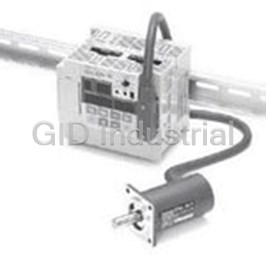
Cam Positioners With High Speed and High Precision Double Machine Productivity 3F88L160
Cam Positioners With High Speed and High Precision Double Machine Productivity 3F88L162
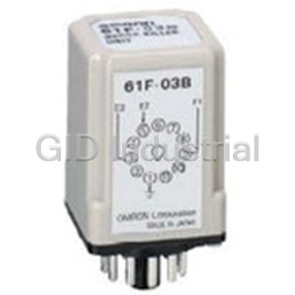
Controllers SURGE SUPRESSOR 61F-03B
Controllers SURGE SUPRESSOR 61F-04B
Conductive Level Controller 61F-GP-N224VAC
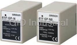
Compact Plug-In Conductive Level Controller, 120VAC Rated Supply Voltage 61F-GP-N2-AC120
Request a Quote

The quote request has been received
Close

Facing challenges or have inquiries? Feel free to contact us!
Call Us +1-469-283-2440
What they say about us
FANTASTIC RESOURCE
One of our top priorities is maintaining our business with precision, and we are constantly looking for affiliates that can help us achieve our goal. With the aid of GID Industrial, our obsolete product management has never been more efficient. They have been a great resource to our company, and have quickly become a go-to supplier on our list!
Bucher Emhart Glass
EXCELLENT SERVICE
With our strict fundamentals and high expectations, we were surprised when we came across GID Industrial and their competitive pricing. When we approached them with our issue, they were incredibly confident in being able to provide us with a seamless solution at the best price for us. GID Industrial quickly understood our needs and provided us with excellent service, as well as fully tested product to ensure what we received would be the right fit for our company.
Fuji
HARD TO FIND A BETTER PROVIDER
Our company provides services to aid in the manufacture of technological products, such as semiconductors and flat panel displays, and often searching for distributors of obsolete product we require can waste time and money. Finding GID Industrial proved to be a great asset to our company, with cost effective solutions and superior knowledge on all of their materials, it’d be hard to find a better provider of obsolete or hard to find products.
Applied Materials
CONSISTENTLY DELIVERS QUALITY SOLUTIONS
Over the years, the equipment used in our company becomes discontinued, but they’re still of great use to us and our customers. Once these products are no longer available through the manufacturer, finding a reliable, quick supplier is a necessity, and luckily for us, GID Industrial has provided the most trustworthy, quality solutions to our obsolete component needs.
Nidec Vamco
TERRIFIC RESOURCE
This company has been a terrific help to us (I work for Trican Well Service) in sourcing the Micron Ram Memory we needed for our Siemens computers. Great service! And great pricing! I know when the product is shipping and when it will arrive, all the way through the ordering process.
Trican Well Service
GO TO SOURCE
When I can't find an obsolete part, I first call GID and they'll come up with my parts every time. Great customer service and follow up as well. Scott emails me from time to time to touch base and see if we're having trouble finding something.....which is often with our 25 yr old equipment.
ConAgra Foods