

 Manufacturers
OMRON AUTOMATION A16-5DSY
Description
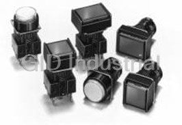
Switch Access Push Button Switch LED
A16-5DSY
Part Number
A16-5DSY
Price
Request Quote
Manufacturer
OMRON AUTOMATION
Lead Time
Request Quote
Category
Sensors and Transducers » Switch Accessories
Specifications
Manufacturer
Omron Automation
Manufacturers Part #
A16-5DSY
Sub-Categories
Switch Accessories
Factory Pack Quantity
1
Datasheet

Extracted Text
Pushbutton Switch (Detachable) (Lighted/Non-Lighted) (Cylindrical 16-dia.) A16 CSM_A16_DS_E_11_2 Separate Construction with Cylindrical 16-dia. Body • Miniature design of 28.5 mm, the smallest class in the industry. • Detachable Switch. • The same contacts can be used for both standard loads and microloads. • Easy-to-wire terminal arrangement. • Certified for EN 60947-5-1. Refer to Safety Precautions for All Pushbutton Switches/ Indicators and Safety Precautions on page 24. List of Models Model Rectangular Square Round Solder terminals A16@-J Series A16@-A Series A16@-T Series PCB terminals A16@-J Series A16@-A Series A16@-T Series Voltage-reduction lighting solder A16@-J Series A16@-A Series A16@-T Series terminals Screw-less clamp models A16@-J Series A16@-A Series A16@-T Series The button colors when the buttons are lit and when they are not lit are shown below. Use these colors as reference only. Button Colors The actual colors may vary. When not lit When lit R Y PY G W A PW B (Red) (Yellow) (Pure yellow) (Green) (White) (Blue) (Pure white) (Black) 1 A16 Model Number Structure Model Number Legend ..... The model numbers used to order sets of Units are illustrated below. One set comprises the Pushbutton, Lamp (lighted models only), Case, and Switch. For information on combinations, refer to Ordering Information on pages 3 to 7. (1) (2) (3) (4) (5) (6) (7) A16 5 L - J R M - 24D - 2 (1) Degree of Protection (7) Contact Configuration Symbol Protection Symbol Type Terminal No symbol IP40 1 SPDT Solder Terminal Oil-resistant 5 2DPDT IP66 1P SPDT PCB Terminal (2) Lighted/Non-lighted 2P DPDT Symbol Type 2S DPDT Screw-less Clamp No symbol Non-lightedOnly DPDT contacts are available with Screw- Less Clamp. L Lighted Consult your OMRON representative (3) Shape of Pushbutton concerning pricing and delivery timing for PCB terminals and screw-less clamp connectors. Symbol Shape (6) Light Source Rectan- J 2-way guard gular (5) Switch Operation Operating Rated Symbol Type A Square 2-way guard voltage voltage Symbol Operation (4) Color of Pushbutton Projecting No symbol Non-lighted T Round M Momentary model Symbol Color 5 5 VAC/VDC 6 VAC/VDC Incan- A Alternate RRed 12 descent 12 VAC/VDC 14 VAC/VDC Momentary-operation: lamp YYellow 24 24 VAC/VDC 28 VAC/VDC Self-resetting PY Pure yellow 5D 5 ± 5% VDC 5 VDC Alternate-operation: G Green 12 ± 5% Self-holding 12D 12 VAC/VDC WWhite LED VAC/VDC 24 ± 5% ABlue Colored Illumination 24D 24 VAC/VDC VAC/VDC PW Pure white Unlit Lit Voltage Reduction Unit (24-V Built-in LED) Black (non-lighted White Color B models only) Operating Rated The built-in Symbol Type Color illuminated models are also voltage voltage LED is colored. available (see page 8). 100 to 110 100/110 Order the parts separately. T1 VAC/VDC VAC/VDC LED 200 to 220 200/220 T2 VAC/VDC VAC/VDC Solder terminals are available only with 100-V models. The Voltage Reduction Unit is not available for models with PCB terminals. “T2” is available only for the Screw-less Clamp type. 2 A16 Ordering Information Ordering as a Set ................. The model numbers used to order sets of Units are given in the following tables. One set comprises the Pushbutton, Lamp (lighted models only), Case, and Switch. Solder Terminal Models Rectangular Models IP40 A16@-J Item Momentary operation Alternate operation Pushbutton color Operating (Self-resetting) (Self-holding) symbol *1 Output Lighting voltage R: red, Y: yellow 5 VDC A16L-J@M-5D-1 A16L-J@A-5D-1 LED without PY: pure yellow Voltage 12 VAC/VDC A16L-J@M-12D-1 A16L-J@A-12D-1 G: green, A: blue Reduction W: white Unit 24 VAC/VDC A16L-J@M-24D-1 A16L-J@A-24D-1 PW: pure white SPDT 5 VAC/VDC A16L-J@M-5-1 A16L-J@A-5-1 R: red, Y: yellow Incandescent PY: pure yellow 12 VAC/VDC A16L-J@M-12-1 A16L-J@A-12-1 lamp G: green, W: white 24 VAC/VDC A16L-J@M-24-1 A16L-J@A-24-1 A: blue B: black *2 Non-lighted A16-J@M-1 A16-J@A-1 R: red, Y: yellow 5 VDC A16L-J@M-5D-2 A16L-J@A-5D-2 LED without PY: pure yellow Voltage 12 VAC/VDC A16L-J@M-12D-2 A16L-J@A-12D-2 G: green, A: blue Reduction W: white Unit 24 VAC/VDC A16L-J@M-24D-2 A16L-J@A-24D-2 PW: pure white DPDT 5 VAC/VDC A16L-J@M-5-2 A16L-J@A-5-2 R: red, Y: yellow Incandescent PY: pure yellow 12 VAC/VDC A16L-J@M-12-2 A16L-J@A-12-2 lamp G: green, W: white 24 VAC/VDC A16L-J@M-24-2 A16L-J@A-24-2 A: blue B: black *2 Non-lighted A16-J@M-2 A16-J@A-2 *1. Enter the desired color symbol for the Pushbutton in the @. *2. Black (“B”) Pushbuttons are only available for non-lighted models. Oil-resistant IP66 Item Momentary operation Alternate operation Pushbutton color Operating (Self-resetting) (Self-holding) symbol *1 Output Lighting voltage R: red, Y: yellow 5 VDC A165L-J@M-5D-1 A165L-J@A-5D-1 LED without PY: pure yellow Voltage 12 VAC/VDC A165L-J@M-12D-1 A165L-J@A-12D-1 G: green, A: blue Reduction W: white Unit 24 VAC/VDC A165L-J@M-24D-1 A165L-J@A-24D-1 PW: pure white SPDT 5 VAC/VDC A165L-J@M-5-1 A165L-J@A-5-1 R: red, Y: yellow Incandescent PY: pure yellow 12 VAC/VDC A165L-J@M-12-1 A165L-J@A-12-1 lamp G: green, W: white 24 VAC/VDC A165L-J@M-24-1 A165L-J@A-24-1 A: blue B: black *2 Non-lighted A165-J@M-1 A165-J@A-1 R: red, Y: yellow 5 VDC A165L-J@M-5D-2 A165L-J@A-5D-2 LED without PY: pure yellow Voltage 12 VAC/VDC A165L-J@M-12D-2 A165L-J@A-12D-2 G: green, A: blue Reduction W: white Unit 24 VAC/VDC A165L-J@M-24D-2 A165L-J@A-24D-2 PW: pure white DPDT 5 VAC/VDC A165L-J@M-5-2 A165L-J@A-5-2 R: red, Y: yellow Incandescent PY: pure yellow 12 VAC/VDC A165L-J@M-12-2 A165L-J@A-12-2 lamp G: green, W: white 24 VAC/VDC A165L-J@M-24-2 A165L-J@A-24-2 A: blue B: black *2 Non-lighted A165-J@M-2 A165-J@A-2 *1. Enter the desired color symbol for the Pushbutton in the @. *2. Black (“B”) Pushbuttons are only available for non-lighted models. Individual models: Refer to pages 9 to 13. ■ Ratings: Refer to page 16. ■ Characteristics: Refer to page 16. (The Pushbutton, Lamp, Case, and Switch can be ordered ■ Accessories: Refer to page 15. separately.) 3 A16 Ordering Information Ordering as a Set ................. The model numbers used to order sets of Units are given in the following tables. One set comprises the Pushbutton, Lamp (lighted models only), Case, and Switch. Solder Terminal Models Square Models IP40 A16@-A Item Momentary operation Alternate operation Pushbutton color Operating (Self-resetting) (Self-holding) symbol *1 Output Lighting voltage R: red, Y: yellow 5 VDC A16L-A@M-5D-1 A16L-A@A-5D-1 LED without PY: pure yellow Voltage 12 VAC/VDC A16L-A@M-12D-1 A16L-A@A-12D-1 G: green, A: blue Reduction W: white Unit 24 VAC/VDC A16L-A@M-24D-1 A16L-A@A-24D-1 PW: pure white SPDT 5 VAC/VDC A16L-A@M-5-1 A16L-A@A-5-1 R: red, Y: yellow Incandescent PY: pure yellow 12 VAC/VDC A16L-A@M-12-1 A16L-A@A-12-1 lamp G: green, W: white 24 VAC/VDC A16L-A@M-24-1 A16L-A@A-24-1 A: blue B: black *2 Non-lighted A16-A@M-1 A16-A@A-1 R: red, Y: yellow 5 VDC A16L-A@M-5D-2 A16L-A@A-5D-2 LED without PY: pure yellow Voltage 12 VAC/VDC A16L-A@M-12D-2 A16L-A@A-12D-2 G: green, A: blue Reduction W: white Unit 24 VAC/VDC A16L-A@M-24D-2 A16L-A@A-24D-2 PW: pure white DPDT 5 VAC/VDC A16L-A@M-5-2 A16L-A@A-5-2 R: red, Y: yellow Incandescent PY: pure yellow 12 VAC/VDC A16L-A@M-12-2 A16L-A@A-12-2 lamp G: green, W: white 24 VAC/VDC A16L-A@M-24-2 A16L-A@A-24-2 A: blue B: black *2 Non-lighted A16-A@M-2 A16-A@A-2 *1. Enter the desired color symbol for the Pushbutton in the @. *2. Black (“B”) Pushbuttons are only available for non-lighted models. Oil-resistant IP66 Item Momentary operation Alternate operation Pushbutton color Operating (Self-resetting) (Self-holding) symbol *1 Output Lighting voltage R: red, Y: yellow 5 VDC A165L-A@M-5D-1 A165L-A@A-5D-1 LED without PY: pure yellow Voltage 12 VAC/VDC A165L-A@M-12D-1 A165L-A@A-12D-1 G: green, A: blue Reduction W: white Unit 24 VAC/VDC A165L-A@M-24D-1 A165L-A@A-24D-1 PW: pure white SPDT 5 VAC/VDC A165L-A@M-5-1 A165L-A@A-5-1 R: red, Y: yellow Incandescent PY: pure yellow 12 VAC/VDC A165L-A@M-12-1 A165L-A@A-12-1 lamp G: green, W: white 24 VAC/VDC A165L-A@M-24-1 A165L-A@A-24-1 A: blue B: black *2 Non-lighted A165-A@M-1 A165-A@A-1 R: red, Y: yellow 5 VDC A165L-A@M-5D-2 A165L-A@A-5D-2 LED without PY: pure yellow Voltage 12 VAC/VDC A165L-A@M-12D-2 A165L-A@A-12D-2 G: green, A: blue Reduction W: white Unit 24 VAC/VDC A165L-A@M-24D-2 A165L-A@A-24D-2 PW: pure white DPDT 5 VAC/VDC A165L-A@M-5-2 A165L-A@A-5-2 R: red, Y: yellow Incandescent PY: pure yellow 12 VAC/VDC A165L-A@M-12-2 A165L-A@A-12-2 lamp G: green, W: white 24 VAC/VDC A165L-A@M-24-2 A165L-A@A-24-2 A: blue B: black *2 Non-lighted A165-A@M-2 A165-A@A-2 *1. Enter the desired color symbol for the Pushbutton in the @. *2. Black (“B”) Pushbuttons are only available for non-lighted models. Individual models: Refer to pages 9 to 13. ■ Ratings: Refer to page 16. ■ Characteristics: Refer to page 16. (The Pushbutton, Lamp, Case, and Switch can be ordered ■ Accessories: Refer to page 15. separately.) 4 A16 Ordering Information Ordering as a Set ................. The model numbers used to order sets of Units are given in the following tables. One set comprises the Pushbutton, Lamp (lighted models only), Case, and Switch. Solder Terminals Round Models IP40 A16@-T Item Momentary operation Alternate operation Pushbutton color Operating (Self-resetting) (Self-holding) symbol *1 Output Lighting voltage R: red, Y: yellow 5 VDC A16L-T@M-5D-1 A16L-T@A-5D-1 LED without PY: pure yellow Voltage 12 VAC/VDC A16L-T@M-12D-1 A16L-T@A-12D-1 G: green, A: blue Reduction W: white Unit 24 VAC/VDC A16L-T@M-24D-1 A16L-T@A-24D-1 PW: pure white SPDT 5 VAC/VDC A16L-T@M-5-1 A16L-T@A-5-1 R: red, Y: yellow Incandescent PY: pure yellow 12 VAC/VDC A16L-T@M-12-1 A16L-T@A-12-1 lamp G: green, W: white 24 VAC/VDC A16L-T@M-24-1 A16L-T@A-24-1 A: blue B: black *2 Non-lighted A16-T@M-1 A16-T@A-1 R: red, Y: yellow 5 VDC A16L-T@M-5D-2 A16L-T@A-5D-2 LED without PY: pure yellow Voltage 12 VAC/VDC A16L-T@M-12D-2 A16L-T@A-12D-2 G: green, A: blue Reduction W: white Unit 24 VAC/VDC A16L-T@M-24D-2 A16L-T@A-24D-2 PW: pure white DPDT 5 VAC/VDC A16L-T@M-5-2 A16L-T@A-5-2 R: red, Y: yellow Incandescent PY: pure yellow 12 VAC/VDC A16L-T@M-12-2 A16L-T@A-12-2 lamp G: green, W: white 24 VAC/VDC A16L-T@M-24-2 A16L-T@A-24-2 A: blue B: black *2 Non-lighted A16-T@M-2 A16-T@A-2 *1. Enter the desired color symbol for the Pushbutton in the @. *2. Black (“B”) Pushbuttons are only available for non-lighted models. Oil-resistant IP66 Item Momentary operation Alternate operation Pushbutton color Operating (Self-resetting) (Self-holding) symbol *1 Output Lighting voltage R: red, Y: yellow 5 VDC A165L-T@M-5D-1 A165L-T@A-5D-1 LED without PY: pure yellow Voltage 12 VAC/VDC A165L-T@M-12D-1 A165L-T@A-12D-1 G: green, A: blue Reduction W: white Unit 24 VAC/VDC A165L-T@M-24D-1 A165L-T@A-24D-1 PW: pure white SPDT 5 VAC/VDC A165L-T@M-5-1 A165L-T@A-5-1 R: red, Y: yellow Incandescent PY: pure yellow 12 VAC/VDC A165L-T@M-12-1 A165L-T@A-12-1 lamp G: green, W: white 24 VAC/VDC A165L-T@M-24-1 A165L-T@A-24-1 A: blue B: black *2 Non-lighted A165-T@M-1 A165-T@A-1 R: red, Y: yellow 5 VDC A165L-T@M-5D-2 A165L-T@A-5D-2 LED without PY: pure yellow Voltage 12 VAC/VDC A165L-T@M-12D-2 A165L-T@A-12D-2 G: green, A: blue Reduction W: white Unit 24 VAC/VDC A165L-T@M-24D-2 A165L-T@A-24D-2 PW: pure white DPDT 5 VAC/VDC A165L-T@M-5-2 A165L-T@A-5-2 R: red, Y: yellow Incandescent PY: pure yellow 12 VAC/VDC A165L-T@M-12-2 A165L-T@A-12-2 lamp G: green, W: white 24 VAC/VDC A165L-T@M-24-2 A165L-T@A-24-2 A: blue B: black *2 Non-lighted A165-T@M-2 A165-T@A-2 *1. Enter the desired color symbol for the Pushbutton in the @. *2. Black (“B”) Pushbuttons are only available for non-lighted models. Individual models: Refer to pages 9 to 13. ■ Ratings: Refer to page 16. ■ Characteristics: Refer to page 16. (The Pushbutton, Lamp, Case, and Switch can be ordered ■ Accessories: Refer to page 15. separately.) 5 A16 Ordering Information Ordering as a Set ................. The model numbers used to order sets of Units are given in the following tables. One set comprises the Pushbutton, Lamp (lighted models only), Case, and Switch. Models with Reduced-voltage Lighting and Solder Terminals A16@-T1 Note: Models with voltage ratings of 200 to 220 VAC/DC (T2 models) are listed with models with screw-less clamp IP40 Item Momentary operation Alternate operation Pushbutton color (Self-resetting) (Self-holding) symbol * Output Lighting Operating voltage R: red, Y: yellow SPDT 100/110 VAC/VDC A16L-Δ@M-T1-1 A16L-Δ@A-T1-1 LED (with built-in PY: pure yellow reduced-voltage G: green, W: white lighting function) A: blue DPDT 100/110 VAC/VDC A16L-Δ@M-T1-2 A16L-Δ@A-T1-2 PW: pure white * Enter the desired shape for the Pushbutton in Δ: J (rectangular), A (square), or T (round). Enter the desired color symbol for the Pushbutton in the @. Oil-resistant IP66 Item Momentary operation Alternate operation Pushbutton color (Self-resetting) (Self-holding) symbol * Output Lighting Operating voltage R: red, Y: yellow SPDT 100/110 VAC/VDC A165L-Δ@M-T1-1 A165L-Δ@A-T1-1 LED (with built-in PY: pure yellow G: green, W: white reduced-voltage A: blue DPDT lighting function) 100/110 VAC/VDC A165L-Δ@M-T1-2 A165L-Δ@A-T1-2 PW: pure white * Enter the desired shape for the Pushbutton in Δ: J (rectangular), A (square), or T (round). Enter the desired color symbol for the Pushbutton in the @. Screw-less Clamp Models A16@-2S IP40 Item Momentary operation Alternate operation Pushbutton color (Self-resetting) (Self-holding) symbol *1 Output Lighting Operating voltage 5 VDC A16L-Δ@M-5D-2S A16L-Δ@A-5D-2S LED 12 VAC/VDC A16L-Δ@M-12D-2S A16L-Δ@A-12D-2S R: red, Y: yellow PY: pure yellow 24 VAC/VDC A16L-Δ@M-24D-2S A16L-Δ@A-24D-2S G: green, W: white DPDT LED (with built-in 100/110 VAC/VDC A16L-Δ@M-T1-2S A16L-Δ@A-T1-2S A: blue reduced-voltage PW: pure white 200/220 VAC/VDC A16L-Δ@M-T2-2S A16L-Δ@A-T2-2S lighting function) B: black *2 Non-lighted A16-Δ@M-2S A16-Δ@A-2S *1. Enter the desired shape for the Pushbutton in Δ: J (rectangular), A (square), or T (round). Enter the desired color symbol for the Pushbutton in the @. *2. Black (“B”) Pushbuttons are only available for non-lighted models. Oil-resistant IP66 Item Momentary operation Alternate operation Pushbutton color (Self-resetting) (Self-holding) symbol *1 Output Lighting Operating voltage 5 VDC A165L-Δ@M-5D-2S A165L-Δ@A-5D-2S LED 12 VAC/VDC A165L-Δ@M-12D-2S A165L-Δ@A-12D-2S R: red, Y: yellow PY: pure yellow 24 VAC/VDC A165L-Δ@M-24D-2S A165L-Δ@A-24D-2S G: green, W: white DPDT LED (with built-in A: blue 100/110 VAC/VDC A165L-Δ@M-T1-2S A165L-Δ@A-T1-2S reduced-voltage PW: pure white 200/220 VAC/VDC A165L-Δ@M-T2-2S A165L-Δ@A-T2-2S B: black *2 lighting function) Non-lighted A165-Δ@M-2S A165-Δ@A-2S *1. Enter the desired shape for the Pushbutton in Δ: J (rectangular), A (square), or T (round). Enter the desired color symbol for the Pushbutton in the @. *2. Black (“B”) Pushbuttons are only available for non-lighted models. 6 A16 Ordering Information Ordering as a Set ................. The model numbers used to order sets of Units are given in the following tables. One set comprises the Pushbutton, Lamp (lighted models only), Case, and Switch. Models with PCB Terminals A16@-P IP40 Item Momentary operation Pushbutton color (Self-resetting) symbol *1 Output Lighting Operating voltage 5 VDC A16L-Δ@M-5D-1P LED 12 VAC/VDC A16L-Δ@M-12D-1P SPDT 24 VAC/VDC A16L-Δ@M-24D-1P R: red Y: yellow Non-lighted A16-Δ@M-1P PY: pure yellow G: green A: blue 5 VDC A16L-Δ@M-5D-2P W: white B: black *2 LED 12 VAC/VDC A16L-Δ@M-12D-2P DPDT 24 VAC/VDC A16L-Δ@M-24D-2P Non-lighted A16-Δ@M-2P Note: Contact your OMRON representative about Selector Switches and Key Selector Switches. *1. Enter the desired shape for the Pushbutton in Δ: J (rectangular), A (square), or T (round). Enter the desired color symbol for the Pushbutton in the @. *2. Black (“B”) Pushbuttons are only available for non-lighted models. IP66 Item Momentary operation Pushbutton color (Self-resetting) symbol *1 Output Lighting Operating voltage 5 VDC A165L-Δ@M-5D-1P LED 12 VAC/VDC A165L-Δ@M-12D-1P SPDT 24 VAC/VDC A165L-Δ@M-24D-1P R: red Y: yellow Non-lighted A165-Δ@M-1P PY: pure yellow G: green A: blue 5 VDC A165L-Δ@M-5D-2P W: white B: black *2 LED 12 VAC/VDC A165L-Δ@M-12D-2P DPDT 24 VAC/VDC A165L-Δ@M-24D-2P Non-lighted A165-Δ@M-2P Note: Contact your OMRON representative about Selector Switches and Key Selector Switches. *1. Enter the desired shape for the Pushbutton in Δ: J (rectangular), A (square), or T (round). Enter the desired color symbol for the Pushbutton in the @. *2. Black (“B”) Pushbuttons are only available for non-lighted models. 7 A16 Ordering Information Illumination Only and Colored Illumination for Models with LEDs With illumination only, the color of the lighted surface is the same when the LED is lit and when it is not lit. Example: Red Illumination Not lit Cap (red) Red Legend plate Operation Unit Dispersion plate (milky white) Lit Red Reflective plunger LED lamp (red) Lamp With colored illumination, the color of the lighted surface is white when the LED is not lit and the LED emits another color when it is lit. Example: Red Illumination Not lit Cap (translucent) White Legend plate Operation Unit Dispersion plate (milky white) Lit Red Reflection plunger LED lamp (red) Lamp Ordering: For colored illumination, order the Pushbutton, Case, Lamp, and Switch separately. Color emitted Operation Unit Case Lamp (LED) Switch when lit IP40 Red A16-@DSR IP40 • Momentary: A16-C@M A16L-@W • Alternate: A16-C@A IP66 Specify one of the fol- IP66 Yellow A16-@DSY A165L-@W lowing symbols in the • Momentary: A165-C@M Refer to page 14. Any Insert one of the fol- box (@). • Alternate: A165-C@A Switch can be mount- lowing symbols into 5: 5 VDC Insert one of the following symbols ed. the box (@). 12: 12 VAC/VDC Green A16-@DSG into the box (@). J: Rectangular 24: 24 VAC/VDC J: Rectangular (2-way guard) A: Square A: Square (2-way guard) T: Round Blue A16-@DA T: Round (projected) 8 A16 Ordering Information Ordering Individually ......... Pushbuttons, Lamps, Cases, and Switches can be ordered separately. Combinations that are not available as sets can be created using individual Units. Also, store the parts as spares for maintenance and repairs. Pushbutton Rectangular Models Square Models Round Models Note: Use IP40 Operation Units with IP40 Case and use IP66 Operation Units with IP66 Case. There is no Legend Plate built into the Operation Unit. A Legend Plate is built into the Operation Unit. However, if the Operation Unit is black (non-lighted models only), a Legend Plate is not built in. Case Note: Operation Unit Sets that combine an Operation Unit and a Case are also available. (Refer to page 10.) Lighted Models Non-lighted Models Lamp LED Incandescent lamp Switch Solder terminals (no transformer) Lighted/non-lighted Note: Switch Units that combine a Lamp and a Switch are also available. (Refer to page 11.) ■ Specifications: Refer to page 16. Ordering set combinations: Refer to pages 3 to 7. ■ Accessories, Replacement, and Tools: Refer to page 15. 9 A16 Ordering Information Units................................ Select a Pushbutton Unit (Pushbutton and Case) and a Switch Unit (Lamp and Switch). Operation Unit Rectangular, square, round Lighted Models Lighted/Non-lighted Model Switch Unit with Voltage-reduction Lighting Switch Unit with Screw-less Clamp Connectors Lamp Voltage-reduction Lamp lighting Lighted/Non-lighted Note: An LED rated 24 VAC/VDC is built-in. Note: Non-lighted models do not include a Lamp. Unit Sets....................... Sets that combine an Operation Unit and a Case. Operation Unit Appearance Classification Model Rectangular (2-way guard) A16-J@M Momentary Square (2-way guard) A16-A@M operation Round (projected) A16-T@M IP40 Rectangular (2-way guard) A16-J@A Alternate operation Square (2-way guard) A16-A@A Round (projected) A16-T@A Rectangular (2-way guard) A165-J@M Momentary Square (2-way guard) A165-A@M operation Round (projected) A165-T@M Oil-resistant IP66 Rectangular (2-way guard) A165-J@A Alternate operation Square (2-way guard) A165-A@A Round (projected) A165-T@A Insert one of the following symbols into the box (@). Symbol Color Remarks RRed YYellow LED indicator, incandescent PY Pure yellow lamp, or non-lighted ABlue WWhite* GY Green LED only G Green Incandescent lamp or non-lighted B Black Non-lighted only * Use this pushbutton color if the illumination color of the LED is white or pure white. 10 A16 Ordering Information Unit Sets....................... Sets that combine a Switch and a Lamp. Switch Units with Incandescent Lamps Appearance Classification Model SPDT A16L-@-1 Standard loads and Solder terminals microloads DPDT A16L-@-2 Switch Units with LED Lamps Appearance Classification Model SPDT A16L-Δ-@-1 Solder terminals DPDT A16L-Δ-@-2 Standard loads and microloads SPDT A16L-Δ-@-1P PCB terminals DPDT A16L-Δ-@-2P Switch Units with Voltage-reduction Lighting (Soldered Terminals) Appearance Classification Operating voltage Model SPDT 100/110 VAC/VDC A16L- Δ-T1-1 Standard loads and microloads DPDT 100/110 VAC/VDC A16L-Δ-T1-2 Note: An LED rated 24 VAC/VDC is built-in. Switch Units with Screw-less Clamp Connectors Appearance Classification Model Non-lighted A16-2S No voltage-reduction lighting A16L-Δ-@-2S Standard loads and DPDT 100/110 VAC/VDC A16L-Δ-T1-2S Voltage-reduc- microloads Lighted tion lighting Note. 200/220 VAC/VDC A16L-Δ-T2-2S Note: The 100-V models and 200-V models an LED rated 24 VAC/VDC is built-in. Insert symbols in Δ and @. Δ @ Operating Symbol Color Symbol Type voltage RRed 5 5 VAC/VDC Y Yellow 12 Incandescent 12 VAC/VDC G Green 24 24 VAC/VDC W White 5D 5 VDC A Blue 12D LED 12 VAC/VDC 24D 24 VAC/VDC Note: If the Pushbutton is pure yellow (PY), use white (W) for the Switch Unit. 11 A16 Ordering Information Ordering Individually ......... Pushbuttons, Lamps, Cases, and Switches can be ordered separately. Combinations that are not available as sets can be created using individual Units. Also, store the parts as spares for maintenance and repairs. Pushbuttons LED Degree of protection IP40 Oil-resistant IP66 Rectangular Square Round Rectangular Square Round Color Red A16L-JR A16L-AR A16L-TR A165L-JR A165L-AR A165L-TR Yellow A16L-JY A16L-AY A16L-TY A165L-JY A165L-AY A165L-TY Pure yellow A16L-JPY A16L-APY A16L-TPY A165L-JPY A165L-APY A165L-TPY Green A16L-JGY A16L-AGY A16L-TGY A165L-JGY A165L-AGY A165L-TGY White* A16L-JW A16L-AW A16L-TW A165L-JW A165L-AW A165L-TW Blue A16L-JA A16L-AA A16L-TA A165L-JA A165L-AA A165L-TA * Use this pushbutton color if the illumination color of the LED is white or pure white. Incandescent Lamps (With the exception of green, the Units are the same as for LEDs.) Degree of protection IP40 Oil-resistant IP66 Rectangular Square Round Rectangular Square Round Color Red A16L-JR A16L-AR A16L-TR A165L-JR A165L-AR A165L-TR Yellow A16L-JY A16L-AY A16L-TY A165L-JY A165L-AY A165L-TY Pure yellow A16L-JPY A16L-APY A16L-TPY A165L-JPY A165L-APY A165L-TPY Green A16L-JG A16L-AG A16L-TG A165L-JG A165L-AG A165L-TG White A16L-JW A16L-AW A16L-TW A165L-JW A165L-AW A165L-TW Blue A16L-JA A16L-AA A16L-TA A165L-JA A165L-AA A165L-TA Non-lighted (Same as Units for incandescent lamps.) Degree of protection IP40 Oil-resistant IP66 Rectangular Square Round Rectangular Square Round Color Red A16L-JR A16L-AR A16L-TR A165L-JR A165L-AR A165L-TR Yellow A16L-JY A16L-AY A16L-TY A165L-JY A165L-AY A165L-TY Pure yellow A16L-JPY A16L-APY A16L-TPY A165L-JPY A165L-APY A165L-TPY Green A16L-JG A16L-AG A16L-TG A165L-JG A165L-AG A165L-TG White A16L-JW A16L-AW A16L-TW A165L-JW A165L-AW A165L-TW Blue A16L-JA A16L-AA A16L-TA A165L-JA A165L-AA A165L-TA Black A16L-JB A16L-AB A16L-TB A165L-JB A165L-AB A165L-TB Ordering set combinations: Refer to pages 3 to 7. ■ Specifications: Refer to page 16. ■ Accessories, Replacement, and Tools: Refer to page 15. 12 A16 Ordering Information Ordering Individually ......... Pushbuttons, Lamps, Cases, and Switches can be ordered separately. Combinations that are not available as sets can be created using individual Units. Also, store the parts as spares for maintenance and repairs. Lamps LED Operating voltage High brightness Light color 5 VDC 12 VAC/VDC 24 VAC/VDC Red A16-5DSR A16-12DSR A16-24DSR Yellow A16-5DSY A16-12DSY A16-24DSY Green A16-5DSG A16-12DSG A16-24DSG White * A16-5DSW A16-12DSW A16-24DSW Blue A16-5DA A16-12DA A16-24DA Pure white A16-5DPW A16-12DPW A16-24DPW Note: 1. If an LED lamp with normal brightness is needed, select a Lamp used in the A3C. 2. For voltage-reduction lighting use the A16-24D@. Only 24 VAC/VDC LED lamps can be used. * Use the white LED together with white or pure yellow Pushbuttons. Incandescent Lamp Appearance Operating voltage Model 5 VAC/VDC A16-5 12 VAC/VDC A16-12 24 VAC/VDC A16-24 Cases Appearance Classification Model Rectangular (2-way guard) A16-CJM Momentary operation Square (2-way guard) A16-CAM Round (projected) A16-CTM IP40 Rectangular (2-way guard) A16-CJA Alternate operation Square (2-way guard) A16-CAA Round (projected) A16-CTA Rectangular (2-way guard) A165-CJM Momentary operation Square (2-way guard) A165-CAM Round (projected) A165-CTM Oil-resistant IP66 Rectangular (2-way guard) A165-CJA Alternate operation Square (2-way guard) A165-CAA Round (projected) A165-CTA ■ Specifications: Refer to page 16. Ordering set combinations: Refer to pages 3 to 7. ■ Accessories, Replacement, and Tools: Refer to page 15. 13 A16 Ordering Information Switches Appearance Classification Model Solder terminal SPDT A16-1 DPDT A16-2 PCB terminal SPDT A16-1P Standard load/microload Lighted/non-lighted (common use) (common use) DPDT A16-2P Screw-less Clamp DPDT A16-2S Switches with Reduced-voltage Lighting Appearance Classification Model Solder terminal SPDT A16-T1-1 100 V DPDT A16-T1-2 Standard load/microload Screw-less Clamp (common use) 100 V A16-T1-2S DPDT 200 V A16-T2-2S Note: For a Switch with Reduced-voltage Lighting, use the A16-24D@. 14 A16 Ordering Information Accessories, Replacements, and Tools Accessories Name Appearance Classification Model Remarks For rectangular models A16ZJ-5050 Switch Guards Cannot be used with the Dust Cover. For square and round A16ZA-5050 models For rectangular models A16ZJ-5060 Cannot be used with the Switch Guard. Dust Covers For square models A16ZA-5060 Can be operated with the Dust Cover attached. For round models A16ZT-5060 Used for covering the panel cutouts for future panel For rectangular models A16ZJ-3003 expansion. Panel Plugs For square models A16ZA-3003 Protective structure: IP40 For round models A16ZT-3003 Color: Black Replacements Name Appearance Classification Model Remarks Rectangu- Oil-resistant A Legend Plate is provided as a Milky A16ZJ-5204 lar IP66 standard feature with the Opera- Oil-resistant tion Unit. However, if the Opera- Legend Plates Square Milky A16ZA-5204 IP66 tion Unit is black (non-lighted models only), a Legend Plate is Oil-resistant Round Milky A16ZT-5204 not provided. IP66 White A16Z@-5001W Insert one of the following letters Red A16Z@-5001R Rectangular LED lamp/incandescent into the box (@). Yellow A16Z@-5001Y lamp/nonlighted J: Rectangular Pure yellow A16Z@-5001PY Color Caps (for A: Square IP40) Blue A16Z@-5001A T: Round LED lamp Green A16Z@-5001GYThe Color Cap is usually supplied. Square Replace the Cap if the color is to Incandescent lamp/non-lighted Green A16Z@-5001G be changed. Non-lighted Black A16Z@-5011B When using an LED indicator, be White A16Z@-5101W sure to use a Color Cap that Red A16Z@-5101R matches the luminescent color of LED lamp/incandescent Yellow A16Z@-5101Y the LED. Round lamp/nonlighted The materials used for the IP40 Pure yellow A16Z@-5101PY Color Caps (for and oil-resistant IP66 are different oil-resistant IP66) Blue A16Z@-5101A so be sure to use a Color Cap that LED lamp Green A16Z@-5101GY matches the specifications of the Incandescent lamp/non-lighted Green A16Z@-5101G Switch. Non-lighted Black A16Z@-5111B Tools Applicable types Knob-type Key-type Emergen- Name Appearance Model Remarks Pushbut- Selector Selector cy Stop Indicator ton Switch Switch Switch Switch Convenient for ex- Operation Unit A3PJ-5080 ● ——— ● tracting Pushbutton Extractor Switches Convenient for Screw Fitting A16Z-3004 ●● ●●● ganged installation. Convenient for ex- Socket Unit Lamp A16Z-5080 ●● ●●● tracting the Switch Extractor and Lamps. 15 A16 Specifications Approved Standard Ratings UL, cUL (File No. E41515) TÜV (EN60947-5-1) (Low Voltage Directive) CCC (GB14048.5) 5 A at 125 VAC, 3 A at 250 VAC (general use) 3 A at 250 VAC 5 A at 125 VAC 3 A at 30 VDC 3 A at 250 VAC 3 A at 30 VDC (resistive) 3 A at 30 VDC Note: Certification has been obtained for the Switch. For detailed information on individual products that have received certification, consult your supplier. Ratings Switch Ratings Super-bright LED Rated Rated Operating Rated voltage Resistive load Internal limiting resistor voltage current voltage 125 VAC 5 A Red, yellow, white: 300 Ω 5 VDC 5 VDC ±5% 250 VAC 3 A Green, blue, pure white: 160 Ω 30 VDC 3 A 8 mA Red, yellow, white: 1 kΩ 12 VAC/VDC 12 VAC/VDC ±5% Green, blue, pure white: 910 Ω Minimum applicable load: 1 mA at 5 VDC 24 VAC/VDC 24 VAC/VDC ±5% 2.4 kΩ Rated values are obtained from tests conducted under the following conditions. Incandescent Lamp 1. Load: Resistive load Rated voltage Rated current Operating voltage 2. Mounting conditions: No vibration and no shock 6 VAC/VDC 60 mA 5 VAC/VDC 3. Temperature: 20 ±2°C 4. Operating frequency: 20 operations/min 14 VAC/VDC 40 mA 12 VAC/VDC 28 VAC/VDC 24 mA 24 VAC/VDC Contact Form Name Contact Voltage-reduction Unit (LED Lamp) Rated voltage Operating voltage Applicable lamp NC DPDT COM 100/110 VAC/VDC 110 VAC/VDC NO (90 to 121 V) A16-24DS@ LED Lamp 200/220 VAC/VDC 220 VAC/VDC (180 to 242 V) Characteristics Socket Unit Screw-less Clamp Item Type Pushbutton Switch Item Screw-Less Clamp 2 Momentary operation: 120 operations/minute max. Recommended wire size 0.5 mm twisted wire or 0.8 mm-dia. solid wire Allowable Mechanical Alternate operation: 60 operations/minute max. *1 operating Twisted 2 2 2 2 frequency 0.3 mm 0.5 mm 0.75 mm 1.25 mm Electrical 20 operations/minute max. *1 wire Usable wires Insulation resistance 100 MΩ min. (at 500V DC) Solid 0.5 mm 0.8 mm 1.0 mm and tensile — Contact resistance 100 mΩ max. (initial value) wire dia. dia. dia. strength Between terminals Tensile 1,000 VAC, 50/60 Hz for 1 minute 10 N 20 N 30 N 40 N of same polarity strength Between terminals Length of exposed wire 10 ±1mm 2,000 VAC, 50/60 Hz for 1 minute of different polarity Dielectric Compliant standards JIS C 2811 Terminal Blocks for Industrial Use strength Between each ter- 2,000 VAC, 50/60 Hz for 1 minute minal and ground Operating Characteristics Between lamp ter- 1,000 VAC, 50/60 Hz for 1 minute *2 Type Pushbutton Switch minals Vibration 10 to 55 Hz, 1.5-mm double amplitude Characteristics IP40 Oil-resistant IP66 Malfunction resistance (malfunction within 1 ms) Operating force (OF) max. 4.41 N 4.91 N 2 Destruction 500 m/s max. Shock Releasing force (RF) min. 0.29 N resistance 2 Malfunction 150 m/s max. (malfunction within 1 ms) Total travel (TT) Approx. 3 mm Momentary operation: 2,000,000 operations min. Mechanical Pretravel (PT) max. 2.5 mm Alternate operation: 200,000 operations min. *1 Durability Lock travel alternate (LTA) min. * 0.5 mm Electrical 100,000 operations min. *1 * Alternate operation models only. Electric shock protection class Class II PTI (tracking characteristic) 175 Degree of contamination 3 (IEC947-5-1) Approx. 10 g (in the case of a lighted Weight DPDT switch with solder terminals) Degree of protection IP40: A16, Oil-resistant IP66: A165 *3 Ambient operating temperature –10°C to 55°C (with no icing or condensation) Ambient operating humidity 35% to 85%RH Ambient storage temperature –25°C to 65°C (with no icing or condensation) *1. Set and reset constitute one operation. *2. With LED and incandescent lamp not mounted. *3. Degree of protection from the front of the panel. 16 A16 Nomenclature Model Structure Pushbutton Cap ●Color of Pushbutton · LED/incandescent models Legend plate Red, Green, Yellow, White, Blue · Neon models Red, Green, White · Non-lighted models Dispersion plate Red, Green, Yellow, White, Blue, Black ●Degree of Protection IP40/Oil-resistant IP66 Reflective plunger ●Flange Shape Rectangular (A16@-J) Square (A16@-A) Lamp Round (A16@-T) Switch ●Switch Specifications 5 A at 125 VAC 3 A at 250 VAC 3 A at 30 VDC Minimum applicable load: 1 mA at 5 VDC ●Terminal Type Solder terminals (tab terminals #110) PCB terminals Screw-less Clamp 17 A16 Dimensions • The Dimension shows 2-switch outputs. • The lamp terminal is also provided with non-lighted models. (Unit: mm) 28.5 Rectangular 9.5 • See page 21 for panel cutouts 21.1 A16@-J 6 10.8 Solder terminals (tab terminals #110) 4 Lamp terminal +0.2 24 min. 16 dia. 0 12.2 18 19 min. M16´1 Lock ring Mounting nut Lamp terminal 2.8 18 15.1 4.85 12.4 15.8 21 Packing (t0.5) 24 (for oil-resistant IP66 only) 28.5 Square • See page 21 for panel cutouts 9.5 21.1 A16@-A 6 10.8 Solder terminals (tab terminals #110) 4 Lamp terminals +0.2 16 dia. 0 19 min. 12.2 18 M16´1 19 min. Lock ring Mounting nut Lamp terminals 2.8 18 15.1 4.85 12.4 15.8 15.1 Packing (t0.5) 18 (for oil-resistant IP66 only) Round 28.5 • See page 21 for panel cutouts 9.5 21.1 A16@-T 6 10.8 Solder terminals (tab terminals #110) 4 Lamp terminals +0.2 16 dia. 0 19 min. 15.1 dia. 12.2 18 18 dia. M16´1 19 min. Lock ring Mounting nut Lamp terminals 2.8 18 4.85 12.4 15.8 18 Packing (t0.5) (for oil-resistant IP66 only) 18 A16 Dimensions • The Dimension shows 2-switch outputs. • The lamp terminal is also provided with non-lighted models. • A rectangular model is listed as an example. (Unit: mm) Rectangular • See page 21 for panel cutouts A16@-J@-@P 28.3 9.5 PCB terminals 26.4 6 23.1 +0.2 21.1 24 min. 16 dia. 0 10.8 4 9.1 ± 0.05 2.5 18.4 20.4 6.3 14.7 ± 0.05 dia. 24 min. 0.5 5.1 ± 0.05 M16´1 Lock ring Mounting nut 18 15.1 4.85 12.4 18.6 0.5 21 Packing (t0.5) 24 (for oil-resistant IP66 only) Rectangular 50.1 42.7 A16@-J@-T1 28.5 9.5 21.1 Voltage-reduction lighting, solder terminals 6 10.8 (tab terminals #110) Panel Cutouts 4 Direction-indication arrow 0.5 +0.2 24 min. 16 dia. 0 12.2 9.8 18 0.5 0.5 M16´1 Marking face Lock ring 23 min. Mounting nut Switch 15.1 (22.4) 8.8 16.6 18 20.6 2.8 2.8 12.4 21 Packing (t0.5) (for oil-resistant IP66 only) 24 Rectangular 2 48.9 9.5 A16@-J@-2S, T1-2S, T2-2S 10.8 Panel Cutouts 6 4 Screw-less Clamp +0.2 25 min. 16 0 dia. 24 23.9 M16´1 Switch dismounting lever Lock ring Mounting nut 33 min. 15.1 (31.7) 27.4 23.5 18 21 Packing (t0.5) 24 (for oil-resistant IP66 only) Lamps LED Incandescent Lamp A16-5D@/-12D@/-24D@ A16-5/-12/-24 12 max. 4 12 max. 4 Cathode (-) 0.5 dia. 0.25 6 dia. 2.54 6 dia. 2.8 Anode (+) * * The voltage display surface is the same color as the illumination color. The opposite surface is light gray. (For pure white, the entire surface is light gray.) 19 18 24 18 A16 Dimensions (Unit: mm) Accessories, Tools, and Components Extractor 20 A3PJ-5080 15 5 10 50 25 Legend Plates A16ZJ-520@ A16ZA-520@ A16ZT-520@ 18.9 12.9 dia. 12.9 12.9 12.9 13.4 dia. 0.6 0.6 0.6 Note: 1. The panel is 0.6 mm thick. Screw Fitting 2. The panel is made of the materials listed in the following table. A16Z-3004 60 Degree of 2 Color Materials protection IP40 18 dia. Milky Polyalylate resin IP66 IP40 Polycarbonate resin Transparent IP66 Polyalylate resin Panel Plugs (Black Resin) Select the Plug that fits the panel design and Rectangular Square Round mount from the front of the Panel. Panel cutouts A16ZJ-3003 A16ZA-3003 A16ZT-3003 are the same as those for Switches. Protective structure: IP40 Color: Black 18 dia. 18 Rough surface Lock Ring 15.8 ± 0.1 dia. Rough surface +0.2 0 15 dia. 2 0 -0.1 t=1 17.9 ± 0.1 Socket Unit Lamp Extractor 80 A16Z-5080 8 20 20 17.9 ± 0.1 2 12 @12 10 A16 Dimensions (Unit: mm) Panel Cutouts Solder Terminals and Screw-less Clamp Connectors PCB Terminals Square A16@-A/M16@-A Square A16@-A/M16@-A Rectangular A16@-@J/M16@-@J Rectangular A16@-J/M16@-J Round A16@-T/M16@-T Round A16@-T/M16@-T (Top View) (Top View) (Top View) (Top View) 24 min. +0.2 24 min. +0.2 16 dia. 16 0 dia. 0 (25 min.) +0.2 +0.2 16 dia. 19 min. 16 dia. 19 min. 0 0 (25 min.) (25 min.) 9.1 ± 0.05 19 min. 19 min. 19 min. 24 min. (33 min.) 14.7 ± 0.05 dia. (33 min.) (33 min.) 5.1 ± 0.05 Note:Make sure the thickness of the mounting panel is between 0.5 and 3.2 Note:Ensure that the variation in the distance between the centers of mm. If, however, a Switch Guard or Dust Cover is used, the thickness neighboring mounting holes is less than ±0.1 mm. of the mounting panel must be between 0.5 and 2 mm.Make sure the thickness of the mounting panel is between 0.5 and 3.2 If the panel is to be finished with coating, etc., make sure that the panel mm. If, however, a Switch Guard or Dust Cover is used, the thickness meets the specified dimensions after coating. of the mounting panel must be between 0.5 and 2 mm. Figures in parentheses are for Screw-less Clamp Connectors.If the panel is to be finished with coating, etc., make sure that the panel meets the specified dimensions after coating. Terminal Arrangement Models without Reduced-voltage Lighting (Non-lighted Pushbutton Switches are also provided with lamp terminals.) Solder Terminals Lighted SPDT Switches Lighted DPDT Switches Terminal Arrangement Terminal Arrangement (Bottom View) (Bottom View) Dimensions of Dimensions of Terminal Holes Terminal Holes NC NC NC L- L- NO NO NO 2.6 7.4 2.6 7.4 0.9 0.9 COM COM COM SW1 SW1 SW2 12.2 1.5 12.2 1.5 18 2.8 Lamp terminal 18 Lamp terminal 2.8 Note: The L+ is not shown on the Switch. Note: The L+ is not shown on the Switch. 21 A16 Dimensions (Unit: mm) PCB Terminals (Lamp terminals are also present on non-lighted models.) Lighted SPDT Switches Lighted DPDT Switches Terminal Arrangement Terminal Arrangement Model, rating, and lot (Bottom View) (Bottom View) number indication Side with TOP indicated Side with TOP indicated Dimensions of Dimensions of PCB Terminals PCB Terminals 5.3 NC NC 5.3 NC L- L- 3.5 3.5 NO NO NO 1.5 1.5 COM COM COM SW 1 SW 2 SW 1 0.8 0.8 4.85 4.85 2.7 2.7 12.4 12.4 18.6 Lamp terminal (t=0.5) 18.6 Lamp terminal (t=0.5) PCB Cutouts PCB Cutouts Side with TOP indicated Side with TOP indicated (Bottom View) (Bottom View) A ± 0.1 A ± 0.1 12.4 ± 0.05 12.4 ± 0.05 20 ± 0.1 4.85 ± 0.05 20 ± 0.1 4.85 ± 0.05 L ± 0.1 L ± 0.1 6.3 ± 0.05 6.3 ± 0.05 Five, 1 dia. Two, 5 dia. 6.3 ± 0.05 Two, 5 dia. A = 24 min.: Rectangular A = 24 min.: Rectangular A = 21 min.: Square or round A = 21 min.: Square or round L = 24 min. L = 24 min. Use a PCB with a thickness of 1.6 mm. Use a PCB with a thickness of 1.6 mm. Note: Secure the panel to the board using stud bolts Note: Secure the panel to the board using stud bolts Eight, 1 d if force will be applied to the board after wiring. if force will be applied to the board after wiring. Terminal Arrangement Voltage-reduction Lighting (Lamp terminals are also present on non-lighted models.) Solder Terminals Screw-Less Clamps DPDT lighted models DPDT lighted models Black (Release button) (Bottom view) Side indicating TOP Side with direction arrow Red (Release button) Red (Release button) White (Release button) White (Release button) NC2 - NC1 NC NC Black (Release button) Black (Release button) L NO2 NO1 C2 + C1 NO NO Black (Release button) Black (Release button) L C2 + C1 C C SW1 SW2 12-3.1 dia. (Insertion hole) SW1 SW2 Red (Release button) • The voltage-reduction circuit is built in. • Voltage-reduction lighting models with Screw-Less Clamps (A16L-@T1-2S, A16L-@T2-2S) incorporate voltage-reduction circuits. 22 A16 Dimensions (Unit: mm) Accessory Dimensions Mounted Dimensions with Switch Guard Installed Square Rectangular A16ZA-5050 A16ZJ-5050 Torsion spring 18 Torsion spring 24 18.1 18.1 23.5 23.5 10.5 10.5 Holder (black) Holder (black) Guard (transparent) Guard (transparent) Panel Cutout (Top View) Panel Cutout (Top View) 19 min. +0.2 16 dia. 24.5 min. 0 +0.2 16 dia. 0 19.6 19.6 27 13 13 27 X X Note: This example is for when X is 4.5 Note: This example is for when X is mm. 28 min. 28 min. 4.5 mm. If X is not required, the Switches If X is not required, the can be mounted with a minimum Switches can be mounted with vertical installation pitch of 24 mm a minimum vertical installation min. pitch of 24 mm min. If PCB terminals are used, provide X must be 24 mm or larger. Dust Covers Cover B (transparent) Rectangular Cover A (black) Panel Cutouts +0.2 A16ZJ-5060 16 0 dia. 31 min. 24 25 min. 30 19.6 13.8 27 Cover B (transparent) Square Panel Cutouts Cover A (black) A16ZA-5060 +0.2 16 0 dia. 25 min. 24 25 min. 24 19.6 13.8 27 Cover B (transparent) Round Panel Cutouts Cover A (black) A16ZT-5060 +0.2 25 min. 16 0 dia. 25 min. 24 dia. 19.6 13.8 27 23 A16 Safety Precautions Refer to Safety Precautions for All Pushbutton Switches/Indicators. Using the Microload WARNING • Insert a contact protection circuit, if necessary, to prevent the Do not apply a voltage between the incandescent reduction of life expectancy due to extreme wear on the contacts lamp and the terminal that is greater than the rated caused by loads where inrush current occurs when the contact is voltage. If the incandescent lamp is broken, the opened and closed. operating part may pop out. • The A16 allows both a standard load (125 V at 5A, 250 V at 3 A) and a microload. If a standard load is applied, however, the Always turn OFF the power and wait for 10 minutes microload area cannot be used. If the microload area is used with a before replacing the incandescent lamp. If the lamp is standard load, the contact surface will become rough, and the replaced immediately after the power is turned OFF, opening and closing of the contact for a microload may become the remaining heat may cause burns. unreliable. • The minimum applicable load is the N-level reference value. This value indicates the malfunction reference level for the reliability level of 60% (λ 60) (conforming to JIS C5003). Precautions for Correct Use -6 The equation, λ 60 = 0.5 × 10 /operations indicates that the Mounting estimated malfunction rate is less than 1/2,000,000 operations with • Always make sure that the power is turned OFF before mounting, a reliability level of 60%. removing, or wiring the Switch, or performing maintenance. • Do not tighten the mounting nut more than necessary using tools such as pointed-nose pliers. Doing so will damage the mounting 0.15 mA 30 nut. The tightening torque is 0.29 to 0.49 N·m. Wiring 24 • Solder terminals and quick-connect terminals (#110) are commonly used for terminals. Microload area • Be sure to use electrical wires that are a size appropriate for the applied voltage and carry current (conductor size is 0.5 to 0.75 12 2 mm ). Perform soldering according to the conditions provided Invalid below. If the soldering is not properly performed, the lead wires will area become detached, resulting in short-circuits. 5 1 mA 1. Hand soldering: 350°C, within 3 s 0 2. Dip soldering: 350°C, within 3 s 0.1 1 10 100 1,000 Wait for one minute after soldering before exerting any external Current (mA) force on the solder. LED • Use non-corrosive resin fluid as the flux. • Make sure that the electric cord is wired so that it does not touch • The LED current-limiting resistor is built-in, so external resistance the Unit. If the electric cord touches the Unit, then electric wires with is not required. a heat resistance of 100°C min. must be used. Rated voltage Internal limiting resistor • After wiring the Switch, maintain an appropriate clearance and Red, yellow, white: 300 Ω creepage distance. 5 VDC Green, blue, pure white: 160 Ω Operating Environment Red, yellow, white: 1 kΩ 12 VAC/VDC • This Switch is intended for indoor use only. Using the Switch Green, blue, pure white: 910 Ω outdoors will cause the Switch to fail. If IP40 models are used in 24 VAC/VDC 2.4 kΩ locations subject to dust, metallic particles, or oil, be careful that none of these penetrates the Switch. Others • The IP66 model is designed with a degree of protection so that it • The oil-resistant IP66 uses NBR rubber and is resistant to general will not sustain damage if it is subjected to water from any direction cutting oil and cooling oil. Some particular oils cannot be used with to the front of the panel. the oil-resistant IP66, however, so contact your OMRON • Do not use the Switch submersed in oil or water, or in locations representative for details. continuously subject to splashes of oil or water. Doing so may result • The durability of the Switch depends in the switching conditions. in oil of water entering the Switch. Always test the Switch under actual application conditions to confirm applicability and use the Switch only for the number of switching operations that will not affect performance. Continuing to use the Switch with degraded performance will eventually result insulation faults between circuits, burning of the Switch, or other failures. • If the panel is to be finished with coating, etc., make sure that the panel meets the specified dimensions after the coating. • Do not subject the Switch to extreme shock or vibration. Doing so will cause malfunctions and damage to the Switch. • Do not let sharp objects come into contact with the Switches that are made of resin. Doing so will damage the Switches, causing scratches on the outside of the operating parts, and malfunction. When handling the Switches, do not throw or drop them. 24 Voltage (V) A16 • Rubber is used inside IP66 models. Do not allow the rubber to Precautions become scratched or foreign matter to become attached to the 1. The mounting panel thickness must be 0.5 to 3.2 mm. rubber. 2. The mounting ring must be tightened to a torque 0.29 to 0.49 N·m. Scratches and foreign matter will degrade the waterproofing, and 3. The procedure for making the mounting hole for the screw-less the Switch may fail operate correctly. clamp connector is described on page 21. A mounting dimension of at least 33 mm is required, however, because the Switch is removed with the screw-less clamp connector mounted to the panel. If Switches are mounted side-by-side separated by less than the specified distance, it may not be possible to remove the Switch. Do not allow the Switch 4. Be sure to mount the Case to the Switch with the correct to drop and hit the ground. orientation. Mount with the dimple on the Case facing in the same direction as the side of the Switch with the direction arrow or the word TOP. Direction arrow dimple Case Switch TOP mark Do not place or drop heavy objects on the Switch. dimple Case Switch Do not operate the Switch with hard or sharp objects. 5. Bend the end of the wire if braided wire is used with the screw- less clamp connector. 6. When wiring, insert the wire until it comes into contact with something. After wiring is completed, pull on the wires to confirm that they are connected securely. Hammer Screwdriver 7. After wiring, ensure that continuous pressure is not applied to the terminals. Screw-less Clamp Wiring Procedure 8. Refer to internal connection diagrams and confirm the terminal Connecting Wires numbers before wiring. 1. Strip the wires for 10 mm (allowable range: 10± 1 mm). 2. If braided wire is used, twist the wire to straighten it out. 3. Insert the wire into the insertion hole while pressing the release button at the side of the hole. (Using a precision screwdriver is recommended.) 4. Let go of the release button to lock the wire into place. 5. After locking, pull on the wire gently to confirm that it is securely locked. Removing Wires 1. Remove wires by pulling them while pressing the release button. Note: When reusing wires that have already been locked one, cut off the end of the wire and strip the wire again before using. 25 A16 Panel Mounting Removing the Switch Unit After mounting the Pushbutton Unit to the panel, snap in the Switch • Grip the part between the Switch holder of the Case and the Switch from the back of the panel. Unit using the A16Z-5080 Extractor, and pull to remove the Switch Unit. Mounting to the Panel • Insert the Pushbutton Unit into the front of the panel, and fix the lock ring and mounting nut from the terminal side. • Make sure that the lock ring is aligned with the thread of the Case and the edge of the lock ring is touching the panel. • Tighten the mounting nuts to a torque of 0.29 to 0.49 N·m. Panel Case Mounting nut Thread A16Z-5080 Extractor Note: Refer to page 21 for PCB terminals. Lock ring Engraving Edge Engraving the Legend Plate • The characters must not be engraved deeper than 0.4 mm. • Apply an alcohol-based paint coating, such as melamine, phthalate, or acrylic resin paint coating. Mounting the Switch Unit • Snap on the Switch Unit to the Pushbutton Unit. Mounting and Replacing the Pushbutton • Make sure that the Switch Unit has the correct orientation when Removing and Mounting the Pushbutton snapping it onto the Case. Align the dimple on the Case with the (1) Remove the Pushbutton as shown in the following diagram. If the groove between the case guards on the NC terminal side of the Pushbutton cannot be removed by hand, use the A3PJ-5080 Switch Unit in the way shown below, and push the Switch Unit into Extractor. the Case until it clicks into place. Confirm that the Switch Unit is securely in place before using. Groove between case guards Pushbutton (2) When mounting the Operation Unit to the Case, press the entire surface of the Operation Unit to surface A of the Case as shown NC terminal dimple in the following diagram. Operation Unit Case Surface A 26 A16 Removing the Lamp Installing the Lamp (1) Removing from the Pushbutton End • When mounting the Lamp, make sure it is facing the direction shown in the following diagram. Insert the Lamp while matching the protruding part of the Lamp and the small guides on the outer Lamp surface of the Case. Grip the Lamp with the Protruding part A16Z-5080 Extractor and pull to remove. • The Lamp can be mounted from the Pushbutton end by using the A16Z-5080 Extractor. The lamp can be mounted by following the opposite procedure for removing the Lamp. (2) Removing from the Switch End The Lamp can be removed by hand once the Switch is removed using the A16Z-5080 Extractor. Mounting the A16Z Dust Cover Cover B 1. Separate the Dust Cover into 2 parts: cover A and cover B. 2. Insert the Case (Pushbutton Unit) into cover A. (transparent) 3. Mount these parts together onto the panel. Pushbutton Unit 4. From the back of the panel, mount the lock ring and secure with the mounting nut. Set 5. Insert cover B into cover A. Ensure that the entire perimeter of cover B A16ZJ-5060 is securely attached to cover A by pressing in different directions. 6. Mount the Switch to the Case. Note: Recommended panel thickness: 0.5 to 2 mm. Cover A (black) Panel Lock ring Mounting nut Switch Mounting the A16Z Switch Guard 1. Insert the Case (Pushbutton Unit) into the Switch Guard. Switch Guard 2. Mount these parts together onto the panel. 3. From the back of the panel, mount the lock ring and secure with the Panel mounting nut. Pushbutton Unit 4. Mount the Switch to the Case. Note: Recommended panel thickness: 0.5 to 2 mm. Lock ring Mounting nut Switch 27 Terms and Conditions Agreement Read and understand this catalog. Please read and understand this catalog before purchasing the products. Please consult your OMRON representative if you have any questions or comments. Warranties. (a) Exclusive Warranty. Omron’s exclusive warranty is that the Products will be free from defects in materials and workmanship for a period of twelve months from the date of sale by Omron (or such other period expressed in writing by Omron). Omron disclaims all other warranties, express or implied. (b) Limitations. OMRON MAKES NO WARRANTY OR REPRESENTATION, EXPRESS OR IMPLIED, ABOUT NON-INFRINGEMENT, MERCHANTABILITY OR FITNESS FOR A PARTICULAR PURPOSE OF THE PRODUCTS. BUYER ACKNOWLEDGES THAT IT ALONE HAS DETERMINED THAT THE PRODUCTS WILL SUITABLY MEET THE REQUIREMENTS OF THEIR INTENDED USE. Omron further disclaims all warranties and responsibility of any type for claims or expenses based on infringement by the Products or otherwise of any intellectual property right. (c) Buyer Remedy. Omron’s sole obligation hereunder shall be, at Omron’s election, to (i) replace (in the form originally shipped with Buyer responsible for labor charges for removal or replacement thereof) the non-complying Product, (ii) repair the non-complying Product, or (iii) repay or credit Buyer an amount equal to the purchase price of the non-complying Product; provided that in no event shall Omron be responsible for warranty, repair, indemnity or any other claims or expenses regarding the Products unless Omron’s analysis confirms that the Products were properly handled, stored, installed and maintained and not subject to contamination, abuse, misuse or inappropriate modification. Return of any Products by Buyer must be approved in writing by Omron before shipment. Omron Companies shall not be liable for the suitability or unsuitability or the results from the use of Products in combination with any electrical or electronic components, circuits, system assemblies or any other materials or substances or environments. Any advice, recommendations or information given orally or in writing, are not to be construed as an amendment or addition to the above warranty. See http://www.omron.com/global/ or contact your Omron representative for published information. Limitation on Liability; Etc. OMRON COMPANIES SHALL NOT BE LIABLE FOR SPECIAL, INDIRECT, INCIDENTAL, OR CONSEQUENTIAL DAMAGES, LOSS OF PROFITS OR PRODUCTION OR COMMERCIAL LOSS IN ANY WAY CONNECTED WITH THE PRODUCTS, WHETHER SUCH CLAIM IS BASED IN CONTRACT, WARRANTY, NEGLIGENCE OR STRICT LIABILITY. Further, in no event shall liability of Omron Companies exceed the individual price of the Product on which liability is asserted. Suitability of Use. Omron Companies shall not be responsible for conformity with any standards, codes or regulations which apply to the combination of the Product in the Buyer’s application or use of the Product. At Buyer’s request, Omron will provide applicable third party certification documents identifying ratings and limitations of use which apply to the Product. This information by itself is not sufficient for a complete determination of the suitability of the Product in combination with the end product, machine, system, or other application or use. Buyer shall be solely responsible for determining appropriateness of the particular Product with respect to Buyer’s application, product or system. Buyer shall take application responsibility in all cases. NEVER USE THE PRODUCT FOR AN APPLICATION INVOLVING SERIOUS RISK TO LIFE OR PROPERTY OR IN LARGE QUANTITIES WITHOUT ENSURING THAT THE SYSTEM AS A WHOLE HAS BEEN DESIGNED TO ADDRESS THE RISKS, AND THAT THE OMRON PRODUCT(S) IS PROPERLY RATED AND INSTALLED FOR THE INTENDED USE WITHIN THE OVERALL EQUIPMENT OR SYSTEM. Programmable Products. Omron Companies shall not be responsible for the user’s programming of a programmable Product, or any consequence thereof. Performance Data. Data presented in Omron Company websites, catalogs and other materials is provided as a guide for the user in determining suitability and does not constitute a warranty. It may represent the result of Omron’s test conditions, and the user must correlate it to actual application requirements. Actual performance is subject to the Omron’s Warranty and Limitations of Liability. Change in Specifications. Product specifications and accessories may be changed at any time based on improvements and other reasons. It is our practice to change part numbers when published ratings or features are changed, or when significant construction changes are made. However, some specifications of the Product may be changed without any notice. When in doubt, special part numbers may be assigned to fix or establish key specifications for your application. Please consult with your Omron’s representative at any time to confirm actual specifications of purchased Product. Errors and Omissions. Information presented by Omron Companies has been checked and is believed to be accurate; however, no responsibility is assumed for clerical, typographical or proofreading errors or omissions. 2015.9 In the interest of product improvement, specifications are subject to change without notice. OMRON Corporation Industrial Automation Company http://www.ia.omron.com/ (c)Copyright OMRON Corporation 2015 All Right Reserved.
Frequently asked questions
How does Electronics Finder differ from its competitors?

Is there a warranty for the A16-5DSY?
Which carrier will Electronics Finder use to ship my parts?
Can I buy parts from Electronics Finder if I am outside the USA?
Which payment methods does Electronics Finder accept?
Why buy from GID?

Quality
We are industry veterans who take pride in our work

Protection
Avoid the dangers of risky trading in the gray market

Access
Our network of suppliers is ready and at your disposal

Savings
Maintain legacy systems to prevent costly downtime

Speed
Time is of the essence, and we are respectful of yours
Related Products
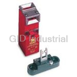
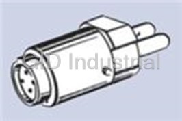
Switch Access Safety Interlock Switch Cord Grip
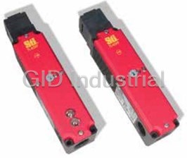
Switch Access Safety Interlock Switch Stainless Steel Alignment Guide
Switch Access Push Button Switch Solder Terminal A16-1
Switch Access Push Button Switch LED A16-12DSG
Switch Access Push Button Switch LED A16-12DSW
Switch Access Push Button Switch LED A16-12DSY
Request a Quote

The quote request has been received
Close

Facing challenges or have inquiries? Feel free to contact us!
Call Us +1-469-283-2440
What they say about us
FANTASTIC RESOURCE
One of our top priorities is maintaining our business with precision, and we are constantly looking for affiliates that can help us achieve our goal. With the aid of GID Industrial, our obsolete product management has never been more efficient. They have been a great resource to our company, and have quickly become a go-to supplier on our list!
Bucher Emhart Glass
EXCELLENT SERVICE
With our strict fundamentals and high expectations, we were surprised when we came across GID Industrial and their competitive pricing. When we approached them with our issue, they were incredibly confident in being able to provide us with a seamless solution at the best price for us. GID Industrial quickly understood our needs and provided us with excellent service, as well as fully tested product to ensure what we received would be the right fit for our company.
Fuji
HARD TO FIND A BETTER PROVIDER
Our company provides services to aid in the manufacture of technological products, such as semiconductors and flat panel displays, and often searching for distributors of obsolete product we require can waste time and money. Finding GID Industrial proved to be a great asset to our company, with cost effective solutions and superior knowledge on all of their materials, it’d be hard to find a better provider of obsolete or hard to find products.
Applied Materials
CONSISTENTLY DELIVERS QUALITY SOLUTIONS
Over the years, the equipment used in our company becomes discontinued, but they’re still of great use to us and our customers. Once these products are no longer available through the manufacturer, finding a reliable, quick supplier is a necessity, and luckily for us, GID Industrial has provided the most trustworthy, quality solutions to our obsolete component needs.
Nidec Vamco
TERRIFIC RESOURCE
This company has been a terrific help to us (I work for Trican Well Service) in sourcing the Micron Ram Memory we needed for our Siemens computers. Great service! And great pricing! I know when the product is shipping and when it will arrive, all the way through the ordering process.
Trican Well Service
GO TO SOURCE
When I can't find an obsolete part, I first call GID and they'll come up with my parts every time. Great customer service and follow up as well. Scott emails me from time to time to touch base and see if we're having trouble finding something.....which is often with our 25 yr old equipment.
ConAgra Foods