

 Manufacturers
OMRON AUTOMATION A165-CTM

Description
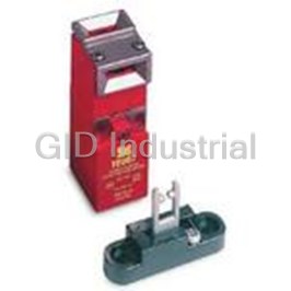
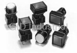
Switch Access Push Button Switch Round Case
A165-CTM
Part Number
A165-CTM
Price
Request Quote
Manufacturer
OMRON AUTOMATION
Lead Time
Request Quote
Category
Sensors and Transducers » Switch Accessories
Specifications
Manufacturer
Omron Automation
Manufacturers Part #
A165-CTM
Industry Aliases
A165-CTM
Sub-Categories
Switch Accessories
Factory Pack Quantity
1
Datasheet

Extracted Text
Indicator M16 Cylindrical 16-dia. Indicator Same basic design as the A16 Pushbutton Switch. UL and cUL approved (File No. E41515). Model Number Structure ■ Model Number Legend Completely Assembled The model numbers used to order sets of Units are illustrated below. One set comprises the Display, Case, Lamp, and Socket. (1) (2) (3) (4) (5) (5) Terminal Type M 1 6 5 - T R - 24D - P Symbol Terminal type No symbol Solder terminals P PCB terminals S Screw-Less Clamp (1) Degree of Protection (4) Light Source Symbol Protection Symbol Type Operating voltage Rated voltage No symbol IP40 (3) Color of Display (2) Shape of Display 5 5 VAC/VDC 6 VAC/VDC 5 IP65 oil-resistant Symbol Color Symbol Shape Incandescent 12 12 VAC/VDC 14 VAC/VDC R Red lamp J Rectangular 24 24 VAC/VDC 28 VAC/VDC G Green A Square 5D 5 ±5% VDC 5 VDC Y Yellow T Round 12D 12 LED ±5% VDC 12 VDC PY Pure yellow 3J Rectangular (3-way guard) 24D 24 ±5% VDC 24 VDC W White BA Square (24-mm square) A Blue Voltage Reduction Unit (24-V Built-in LED) Symbol Type Operating voltage Rated voltage T1 90 to 121 VAC/VDC 110 VAC/VDC LED T2 180 to 242 VAC/VDC 220 VAC/VDC Solder terminals are available only with 100-V models. The Voltage Reduction Unit is not available for models with PCB terminals. Indicator M16 G-127 Pushbutton Switches Ordering Information ■ List of Models Ordering as a Set The model numbers used to order sets of Units are given in the following tables. One set comprises the Display, Case, Lamp, and Socket. M16@-J (Rectangular) Models Solder Terminal Models Appearance Lighting Operating voltage IP40 IP65 oil-resistant Display color symbol (See note.) LED without Voltage 5 VDC M16-J@-5D M165-J@-5D R: red Reduction Unit Y: yellow 12 VDC M16-J@-12D M165-J@-12D G: green 24 VDC M16-J@-24D M165-J@-24D A: blue Incandescent lamp 5 VDC/VAC M16-J@-5 M165-J@-5 W: white PY: Pure yellow 12 VDC/VAC M16-J@-12 M165-J@-12 24 VDC/VAC M16-J@-24 M165-J@-24 M16@-A (Square) Models Solder Terminal Models Appearance Lighting Operating voltage IP40 IP65 oil-resistant Display color symbol (See note.) LED without Voltage 5 VDC M16-A@-5D M165-A@-5D R: red Reduction Unit Y: yellow 12 VDC M16-A@-12D M165-A@-12D G: green 24 VDC M16-A@-24D M165-A@-24D A: blue Incandescent lamp 5 VDC/VAC M16-A@-5 M165-A@-5 W: white PY: Pure yellow 12 VDC/VAC M16-A@-12 M165-A@-12 24 VDC/VAC M16-A@-24 M165-A@-24 M16@-T (Round) Models Solder Terminal Models Appearance Lighting Operating voltage IP40 IP65 oil-resistant Display color symbol (See note.) LED without Voltage 5 VDC M16-T@-5D M165-T@-5D R: red Reduction Unit Y: yellow 12 VDC M16-T@-12D M165-T@-12D G: green 24 VDC M16-T@-24D M165-T@-24D A: blue Incandescent lamp 5 VDC/VAC M16-T@-5 M165-T@-5 W: white PY: Pure yellow 12 VDC/VAC M16-T@-12 M165-T@-12 24 VDC/VAC M16-T@-24 M165-T@-24 Note: Enter the desired color symbol for the Display in @. G-128 Indicator M16 Ordering Individually Displays, Cases, Lamps, and Sockets can be ordered separately. Combinations that are not available as sets can be created using individual parts. Also, store the parts as spares for maintenance and repairs. Display (Refer to page 130.) Rectangular Square Round Note: Use IP40 Displays in combination with IP40 Sock- ets and use IP65 Displays in combination with IP65 Sockets. Case (Refer to page 131.) Note: Display Units, which are combinations of Displays and Cases, are also available. Lighted Models Lamp (Refer to page 130.) Incandescent Lamp Neon Lamp LED Socket (Refer to page 131.) Solder Terminals (Without Voltage Reduction Unit) Note: Socket Units, which are combinations of Lamps and Sockets, are also available. Indicator M16 G-129 Pushbutton Switches Display For LED-lighted Models Sealing IP40 IP65 oil-resistant Appearance Rectangular Square Round Rectangular Square Round Color of Display Red A16L-JR A16L-AR A16L-TR A165L-JR A165L-AR A165L-TR Yellow A16L-JY A16L-AY A16L-TY A165L-JY A165L-AY A165L-TY Pure yellow A16L-JPY A16L-APY A16L-TPY A165L-JPY A165L-APY A165L-TPY Green A16L-JGY A16L-AGY A16L-TGY A165L-JGY A165L-AGY A165L-TGY White A16L-JW A16L-AW A16L-TW A165L-JW A165L-AW A165L-TW Blue A16L-JA A16L-AA A16L-TA A165L-JA A165L-AA A165L-TA Incandescent Lamps (With the exception of green, the Units are the same as for LEDs.) Sealing IP40 IP65 oil-resistant Appearance Rectangular Rectangular Square Round Square Round Color of Display Red A16L-JR A16L-AR A16L-TR A165L-JR A165L-AR A165L-TR Yellow A16L-JY A16L-AY A16L-TY A165L-JY A165L-AY A165L-TY Pure yellow A16L-JPY A16L-APY A16L-TPY A165L-JPY A165L-APY A165L-TPY Green A16L-JG A16L-AG A16L-TG A165L-JG A165L-AG A165L-TG White A16L-JW A16L-AW A16L-TW A165L-JW A165L-AW A165L-TW Blue A16L-JA A16L-AA A16L-TA A165L-JA A165L-AA A165L-TA Neon Lamps Sealing IP40 IP65 oil-resistant Appearance Rectangular Square Rectangular Round Round Square Color of Display Red A16L-JRN A16L-ARN A16L-TRN A165L-JRN A165L-ARN A165L-TRN Green A16L-JGN A16L-AGN A16L-TGN A165L-JGN A165L-AGN A165L-TGN White A16L-JWN A16L-AWN A16L-TWN A165L-JWN A165L-AWN A165L-TWN Lamp LED Color Operating voltage 5 VDC 12 VDC 24 VDC Red A16-5DSR A16-12DSR A16-24DSR Yellow A16-5DSY A16-12DSY A16-24DSY Green A16-5DSG A16-12DSG A16-24DSG White (See note.) A16-5DSW A16-12DSW A16-24DSW Blue A16-5DA A16-12DA A16-24DA Note: Use the white LED when the required illumination color is white or pure yellow. Incandescent Lamp Operating voltage 5 VAC/VDC 12 VAC/VDC 24 VAC/VDC Model A16-5 A16-12 A16-24 G-130 Indicator M16 Neon Lamp Color of lamp Color of Display Operating voltage 100 VAC 200 VAC Red White, red A16-1NRN A16-2NRN Green Green A16-1NGN A16-2NGN Case Appearance Classification Model number IP40 Rectangular A16-CJM Square A16-CAM Round A16-CTM IP65 oil-resistant Rectangular A165-CJM Square A165-CAM Round A165-CTM Socket Appearance Classification Model number Solder terminals M16-0 PCB terminals M16-0P Screw-Less Clamp M16-S Solder terminals Voltage-reduction lighting 100 V M16-T1 Solder terminals Screw-Less Clamp 100 V M16-T1-S 200 V M16-T2-S Specifications ■ Approved Standards Agency Standards File No. UL, cUL (See note.) UL508 E41515 Note: cUL: CSA, C22.2 No. 14 ■ Ratings Super-bright LED Incandescent Lamp Rated Rated current Operating Built-in limiting Rated voltage Rated current Operating voltage voltage voltage resistance 6 VAC/VDC 60 mA 5 VAC/VDC 5 VDC 30 mA (15 mA) 5 VDC ±5% 33 Ω (68 Ω) 14 VAC/VDC 40 mA 12 VAC/VDC 12 VDC 15 mA 12 VDC ±5% 270 Ω (560 Ω) 28 VAC/VDC 24 mA 24 VAC/VDC 24 VDC 10 mA 24 VDC ±5% 1,600 Ω (2,000 Ω) Note: The values in parentheses are for blue Pushbuttons. Neon Lamp Rated voltage Rated current Operating voltage 110 VAC 1.5 mA 100 VAC ±10% 220 VAC 1.5 mA 200 VAC ±10% ■ Characteristics Ambient operating temperature −10°C to 55°C (with no icing or condensation) Ambient operating humidity 35% to 85% Ambient storage temperature −25°C to 65°C Note: Characteristics not provided above are the same as those for the A16. Indicator M16 G-131 Pushbutton Switches Screw-less Clamp Item Screw-less Clamp 2 Recommended wire size 0.5 mm twisted wire or 0.8 mm-dia. solid wire 2 2 2 2 Usable wires and ten- Twisted wire 0.3 mm 0.5 mm 0.75 mm 1.25 mm sile strength Solid wire 0.5 mm dia. 0.8 mm dia. 1.0 mm dia. --- Tensile strength 10 N 20 N 30 N 40 N Length of exposed wire 10 ±1 mm Dimensions Note: 1. All units are in millimeters unless otherwise indicated. 2. Refer to page 134 for details of panel cutout dimensions. Rectangular Square M16-J M16-A Packing (t0.5) Packing (t0.5) Solder terminals Solder terminals 14.6 dia. 14.6 dia. 18 dia. 18 dia. Lamp terminals Lamp terminals Mounting nut Mounting nut Round Lock ring Lock ring M16-T Packing (t0.5) M16 × 1 Solder terminals 18 dia. 15.1 dia. 14.6 dia.18 dia. Lamp terminals Terminal Hole Dimensions Lamp terminals 14.6 dia. 18 dia. Mounting nut Lock ring G-132 Indicator M16 Rectangular The rectangular model is given here as a representative example. M16@-P Lamp terminals are provided even for non-lighting applications. 28.3 PCB terminals 9.5 26.4 6 23.1 Panel Cutouts 21.1 10.8 +0.2 4 24 min. 16 0 dia. 2.5 18.4 20.4 6.3 0.5 24 min. Lock ring Mounting ring 18 15.1 4.85 12.4 18.6 0.5 Recommended panel thickness: 0.5 to 3.2 mm 21 Packing (t0.5) 24 (for oil-resistant IP65 only) Rectangular M16@-T1, T2 Voltage-reduction lighting, solder terminals Panel Cutouts +0.2 25 min. Direction-indication arro Direction-indication arrow w 16 dia. 0 Display 23 min. (Dimension A) Marking face Case Packing (t0.5) Lock ring (for oil-resistant IP65 only) Mounting ring Socket Recommended panel thickness: 0.5 to 3.2 mm Rectangular M16@-S Screw-Less Clamp Socket dismounting lever Lock ring Mounting ring Packing (t0.5) (for oil-resistant IP65 only) Indicator M16 G-133 Pushbutton Switches ■ Terminal Arrangement Solder Terminals Screw-Less Clamp Voltage-reduction Lighting Bottom View Bottom View Bottom View Black Side with TOP indicated Side with TOP indicated Note: The L+ is not shown on the Socket Unit. Red Note: Voltage-reduction lighting mod- els with Screw-Less Clamps (A16L-@T1-2S, A16L-@T2-2S) incorporate voltage-reduction circuits. ■ Panel Cutouts Solder Terminals Solder Terminals Screw-Less Clamp Rectangular M16@-J Square M16@-A Rectangular Round M16@-T M16@-S (Top View) (Top View) (Top View) +0.2 16 dia. 25 min. +0.2 +0.2 0 16 dia. 24 min. 16 dia. 0 0 19 min. 19 min. 19 min. 32 min. (Dimension A) Note: 1. Make sure the thickness of the mounting panel is 0.5 to 3.2 mm. If, however, a Switch Guard or Dust Cover is used, the thickness of the mounting panel must be 0.5 to 2 mm. 2. If the panel is to be finished with coating, etc., make sure that the panel meets the specified dimensions after coating. Installation Refer to the Installation section for the A16. G-134 Indicator M16 Precautions Refer to the Technical Information for Pushbutton Switches (Cat. No. A143) and the Precautions section for the A16. ■ Correct Use Mounting Wiring When mounting the Case onto the Socket Unit, ensure that the orien- When using stranded wire, gather the ends of the strands together tation is correct. Perform mounting with the mark on the Case and before wiring. the TOP mark on the Socket Unit facing in the same direction. When wiring, insert the wire until it comes into contact with some- thing. After wiring is completed, pull on the wires to confirm that they TOP mark are connected securely. After wiring, ensure that continuous pressure is not applied to the ter- minals. Refer to internal connections diagrams and confirm the terminal numbers before performing wiring. • mark Socket Unit Case Screw-Less Clamps Mounting Procedure 1. Strip a length of 10 mm off the end of the wire (allowable range: 10±1 mm). 2. Bunch wire strands together and straighten them. 3. Insert the wire into the insertion hole while pressing the release button at the side of the hole. (Using a precision screwdriver is recommended.) 4. Let go of the release button to lock the wire into place. 5. After locking, pull on the wire gently to confirm that it is securely locked. Removing Procedure Remove wires by pulling them while pressing the release button. Note: When reusing wires that have already been locked, cut off the end of the wire and strip the wire again before using. Indicator M16 G-135 Pushbutton Switches ALL DIMENSIONS SHOWN ARE IN MILLIMETERS. To convert millimeters into inches, multiply by 0.03937. To convert grams into ounces, multiply by 0.03527. In the interest of product improvement, specifications are subject to change without notice. Cat. No. A127-E1-02 G-136 Indicator M16
Frequently asked questions
How does Electronics Finder differ from its competitors?

Is there a warranty for the A165-CTM?
Which carrier will Electronics Finder use to ship my parts?
Can I buy parts from Electronics Finder if I am outside the USA?
Which payment methods does Electronics Finder accept?
Why buy from GID?

Quality
We are industry veterans who take pride in our work

Protection
Avoid the dangers of risky trading in the gray market

Access
Our network of suppliers is ready and at your disposal

Savings
Maintain legacy systems to prevent costly downtime

Speed
Time is of the essence, and we are respectful of yours
Related Products
Switch Access Safety Interlock Switch Cord Grip
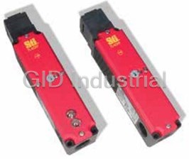
Switch Access Safety Interlock Switch Stainless Steel Alignment Guide
Switch Access Push Button Switch Solder Terminal A16-1
Switch Access Push Button Switch LED A16-12DSG
Switch Access Push Button Switch LED A16-12DSW
Switch Access Push Button Switch LED A16-12DSY
Request a Quote

The quote request has been received
Close

Facing challenges or have inquiries? Feel free to contact us!
Call Us +1-469-283-2440
What they say about us
FANTASTIC RESOURCE
One of our top priorities is maintaining our business with precision, and we are constantly looking for affiliates that can help us achieve our goal. With the aid of GID Industrial, our obsolete product management has never been more efficient. They have been a great resource to our company, and have quickly become a go-to supplier on our list!
Bucher Emhart Glass
EXCELLENT SERVICE
With our strict fundamentals and high expectations, we were surprised when we came across GID Industrial and their competitive pricing. When we approached them with our issue, they were incredibly confident in being able to provide us with a seamless solution at the best price for us. GID Industrial quickly understood our needs and provided us with excellent service, as well as fully tested product to ensure what we received would be the right fit for our company.
Fuji
HARD TO FIND A BETTER PROVIDER
Our company provides services to aid in the manufacture of technological products, such as semiconductors and flat panel displays, and often searching for distributors of obsolete product we require can waste time and money. Finding GID Industrial proved to be a great asset to our company, with cost effective solutions and superior knowledge on all of their materials, it’d be hard to find a better provider of obsolete or hard to find products.
Applied Materials
CONSISTENTLY DELIVERS QUALITY SOLUTIONS
Over the years, the equipment used in our company becomes discontinued, but they’re still of great use to us and our customers. Once these products are no longer available through the manufacturer, finding a reliable, quick supplier is a necessity, and luckily for us, GID Industrial has provided the most trustworthy, quality solutions to our obsolete component needs.
Nidec Vamco
TERRIFIC RESOURCE
This company has been a terrific help to us (I work for Trican Well Service) in sourcing the Micron Ram Memory we needed for our Siemens computers. Great service! And great pricing! I know when the product is shipping and when it will arrive, all the way through the ordering process.
Trican Well Service
GO TO SOURCE
When I can't find an obsolete part, I first call GID and they'll come up with my parts every time. Great customer service and follow up as well. Scott emails me from time to time to touch base and see if we're having trouble finding something.....which is often with our 25 yr old equipment.
ConAgra Foods