

 Manufacturers
OMRON AUTOMATION A3C-4103
Description
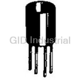
Conn Switch Socket SKT 4 POS Solder ST Thru-Hole
A3C-4103
Part Number
A3C-4103
Price
Request Quote
Manufacturer
OMRON AUTOMATION
Lead Time
Request Quote
Category
Connectors » Connector Socket
Specifications
Manufacturer
Omron Automation
Manufacturers Part #
A3C-4103
Industry Aliases
A3C-4103
Sub-Category
Connector Sockets
Factory Pack Quantity
1
Datasheet

Extracted Text
A3C
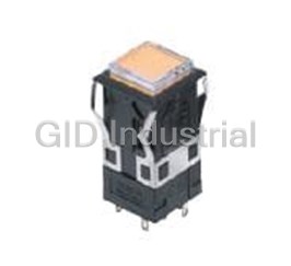
Pushbutton Switch (Lighted/Non-Lighted) (Cylindrical 12-dia.)
CSM_A3C_DS_E_2_1
Pushbutton Switch Series with
Cylindrical 20-mm × 12-dia. Body
• High-intensity uniform surface lighting.
Round body enables easy hole making.
Miniature size with excelle nt feeling of operation.
RoHS Compliant
Refer to Safety Precautions for All Pushbutton Switches and
Safety Precautions on page 12.
List of Models
Appearance Model
Rectangular
A3CJ
Models
Square
A3CA
Models
Round
A3CT
Models
■ Specifications: Refer to page 8. ■ Dimensions: Refer to page 10. ■ Accessories: Refer to page 7.
■ Precautions for correct use and safety precautions: Refer to page 12.
1
A3C
Model Number Legend .............................................When placing your order, specify the individual component part model numbers of
the Pushbutton, Lamp (lighted models only), and Switch, as listed in the ordering
tables below.
For information on combinations, refer to Ordering Information on page 3.
(1) (2) (3) (4) (5) (6)
A3C J - 9 0 A 1 - 24E R
(3) Switch Specifications (5) Lighting
(1) Shape of (2) Terminal Type (4) Lighted/Non- (6) Color of
Standard Load lighted Method
Pushbutton Pushbutton
Sym-
Type
LED Lamp-lighted
For LED
bol
Sym- Sym-
Sym-
Shape Operation Type
Models
Lamp
bol bol
bol 0 Solder terminal
Rectan- AMomentary 0 Non-lighted
Sym- Operating Sym-
J 1a1b
Color
gular
bol voltage bol
B Alternate Illumination
1
only
A Square 05E 5 VDC
R Red
T RoundColored-illumina- 12E 12 VDC Y Yellow
Microload
tion models are
24E 24 VDC
G Green
Sym- also available.
Operation
W White
bol Refer to page 4.
EMomentary
1a1b
"Colored-illumi-
For
Incandescent
F Alternate
nation" models
Incandescent
Lamp-lighted
Standard Load operate in the
Lamp
Models
0.5 A at 250 VAC way shown be-
1 A at 125 VAC low:
Sym-
Sym- Operating
Color
1 A at 30 VDC
bol
Lit
Unlit bol voltage
Microload
R Red
White Color 06 5 VAC/VDC
0.1 A at 125 VAC
Y Yellow
0.1 A at 30 VDC The built-in LED 14 12 VAC/VDC
is colored.
G Green
28 24 VAC/VDC
Minimum applicable load
A Blue
1 mA at 5 VDC
W White
Momentary-action: Self-resetting
Alternate-action: Self-holding
For Non-
Non-lighted
lighted
Models
Models
No symbol
Sym-
Color
bol
R Red
Y Yellow
G Green
W White
A Blue
B Black
2
A3C
Ordering Information
Ordering as a Set ................................ The model numbers used to order sets of Units are given in the following tables. One set comprises
the Pushbutton, Lamp (lighted models only), and Switch.
Rectangular Square Round
Models Models Models
A3CJ A3CA A3CT
Lighted Pushbutton Switches (SPST-NO+SPST-NC Solder Terminals)
Standard load Microload
Operation
Momentary operation (Self-resetting) Alternate operation (Self-holding) Momentary operation (Self-resetting) Pushbutton
color symbol
Shape Lighting Set Set Set
(Color)
A3CJ-90A1-05E@ A3CJ-90B1-05E@ A3CJ-90E1-05E@ R: red
Y: yellow
LED lamp A3CJ-90A1-12E@ A3CJ-90B1-12E@ A3CJ-90E1-12E@
G: green
W: white
A3CJ-90A1-24E@ A3CJ-90B1-24E@ A3CJ-90E1-24E@
Rectangular
R: red
A3CJ-90A1-06@
(A3CJ)
---
Y: yellow
Incandescent
A3CJ-90A1-14@ ---
G: green
lamp
W: white
A3CJ-90A1-28@ A3CJ-90B1-28@
A: blue
Non-lighted A3CJ-90A0-@ A3CJ-90B0-@ A3CJ-90E0-@
B: black *
A3CA-90A1-05E@ A3CA-90B1-05E@ A3CA-90E1-05E@
R: red
Y: yellow
LED lamp A3CA-90A1-12E@ A3CA-90B1-12E@ A3CA-90E1-12E@
G: green
W: white
A3CA-90A1-24E@ A3CA-90B1-24E@ A3CA-90E1-24E@
Square
R: red
A3CA-90A1-06@
(A3CA)
--- Y: yellow
Incandescent
A3CA-90A1-14@ ---
G: green
lamp
W: white
A3CA-90A1-28@ A3CA-90B1-28@
A: blue
Non-lighted A3CA-90A0-@ A3CA-90B0-@ A3CA-90E0-@ B: black *
A3CT-90A1-05E@ A3CT-90B1-05E@ A3CT-90E1-05E@
R: red
Y: yellow
LED lamp A3CT-90A1-12E@ A3CT-90B1-12E@ A3CT-90E1-12E@
G: green
W: white
A3CT-90A1-24E@ A3CT-90B1-24E@ A3CT-90E1-24E@
Round
R: red
A3CT-90A1-06@
(A3CT)
---
Y: yellow
Incandescent
A3CT-90A1-14@ ---
G: green
lamp
W: white
A3CT-90A1-28@ A3CT-90B1-28@
A: blue
Non-lighted A3CT-90A0-@ A3CT-90B0-@ A3CT-90E0-@
B: black *
Note: 1. Enter the desired color symbol for the Pushbutton in the @ at the end of the model number.
2. There are also alternate-operation models that can be used for microloads. Refer to the Switch table on page 6.
* Black ("B") Pushbuttons are only available for non-lighted models.
Individual models: Refer to pages 5 to 6. ■ Specifications: Refer to page 8. ■ Dimensions: Refer to page 10.
(The Pushbutton, Lamp, and Switch can be ordered separately.) ■ Accessories: Refer to page 7.
3
A3C
Ordering Information
Illumination-only and Colored-illumination LED Models
"Illumination only" describes LED models for which the screen color is the same whether the LED is lit or not.
Example: Red LED
Not lit
Cap (red)
Red
Pushbutton
Legend plate (milky white)
Lit
Red
Reflective plunger
LED lamp (red) - - - Lamp
"Colored illumination" describes LED models for which the screen color is white when the LED is not lit and changes to the color of the LED lamp
when the LED is lit.
Example: Red LED
Not lit
White White cap (semi-transparent)
Pushbutton
Legend plate (milky white)
Lit
Red
Reflective plunger
LED lamp (red) - - - Lamp
Ordering: With colored-illumination models, order the Pushbutton, Lamp, and Switch as shown in the following table.
Illuminated color Pushbutton Lamp (LED) Switch
Red A16-@DR
IP40
A3C@-500W Enter one of the
Enter one of the following sym- following symbols in @. Refer to page 6. Make the se-
Yellow bols in @. A16-@DY 5: 5 VDC lection according to the
J: Rectangular 12: 12 VDC shape of the Pushbutton.
A: Square 24: 24 VDC
T: Round
Green A16-@DG
4
A3C
Ordering Information
Ordering Individually ............... Pushbuttons, Lamps, and Switches can be ordered separately. Combinations that are not available as
sets can be created using individual Units. Also, store the parts as spares for maintenance and repairs.
Ordering: Specify a model number from the following page.
LED Lamp Non-lighted Models
Operation Unit Operation Unit
Lamps
LED Lamp Incandescent Lamp
Switch Switch
Ordering set combinations: Refer to page 3. ■ Specifications: Refer to page 8. ■ Dimensions: Refer to page 10.
■ Accessories: Refer to page 7.
5
A3C
Ordering Information
Ordering Individually................Pushbuttons, Lamps, and Switches can be ordered separately. Combinations that are not available as
sets can be created using individual Units. Also, store the parts as spares for maintenance and repairs.
Pushbuttons
LED Lamp Non-lighted Models
Square Round Square Round
Rectangular Rectangular
Shape Shape
Button color Button color
Red A3CJ-500R A3CA-500R A3CT-500R Red A3CJ-500R A3CA-500R A3CT-500R
Yellow A3CJ-500Y A3CA-500Y A3CT-500Y Yellow A3CJ-500Y A3CA-500Y A3CT-500Y
Green A3CJ-500GY A3CA-500GY A3CT-500GY Green A3CJ-500G A3CA-500G A3CT-500G
White A3CJ-500W A3CA-500W A3CT-500W White A3CJ-500W A3CA-500W A3CT-500W
Blue A3CJ-500A A3CA-500A A3CT-500A
Note: The red, yellow, and white Pushbuttons listed above can be used with
either LED lamp-lighted models or incandescent lamp-lighted models.
Black A3CJ-501B A3CA-501B A3CT-501B
Note: Models other than black can also be used with incandescent lamps.
Incandescent Lamp
Square Round
Rectangular
Shape
Button color
Red A3CJ-500R A3CA-500R A3CT-500R
Yellow A3CJ-500Y A3CA-500Y A3CT-500Y
Green A3CJ-500G A3CA-500G A3CT-500G
White A3CJ-500W A3CA-500W A3CT-500W
Blue A3CJ-500A A3CA-500A A3CT-500A
Lamps
Incandescent Lamp
LED Lamp
Color Rated voltage Model
Red Yellow Green White
Rated voltage
6 VAC/DC A16-5
5 VDC A16-5DR A16-5DY A16-5DG A16-5DW
14 VAC/DC A16-12
12 VDC A16-12DR A16-12DY A16-12DG A16-12DW
28 VAC/DC A16-24
24 VDC A16-24DR A16-24DY A16-24DG A16-24DW
Switches
Sealing Degree of protection: IP40
Rectangular Square Round
Shape
Contact type Switch action Terminal
Momentary A3CJ-7011 A3CA-7011 A3CT-7011
Standard load Solder
Alternate A3CJ-7021 A3CA-7021 A3CT-7021
SPST-NO+
SPST NC
Momentary A3CJ-7111 A3CA-7111 A3CT-7111
Microload Solder
Alternate A3CJ-7121 A3CA-7121 A3CT-7121
Ordering set combinations: Refer to page 3. ■ Specifications: Refer to page 8. ■ Dimensions: Refer to page 10.
■ Accessories: Refer to page 7.
6
A3C
Ordering Information
Accessories, Replacements, and Tools
Accessories
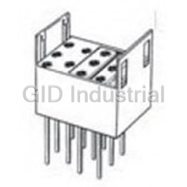
Name Appearance Classification Model Remarks
Wire-wrap terminal A3C-4101
PCB terminal A3C-4102
Socket Cannot be used with Insulation Cover.
Solder terminal A3C-4103
Insulation Cover --- A3C-3002 Cannot be used with Socket.
For rectangular models A3CJ-5050
Switch Guard Cannot be used with Dust Cover.
For square, round models A3CA-5050
Cannot be used with Switch Guard.
Dust Cover For rectangular models A3CJ-5060
Can be used with Dust Cover attached.
Tools
Name Appearance Classification Model Remarks
Tightening Tool --- A3C-3004 The tightening torque is 0.20 to 0.39 N·m.
Extractor --- A3PJ-5080 ---
Replacements
Name Appearance Classification Model Remarks
For rectangular models A3CJ-5201
One Legend Plate (milk-white) is supplied per
Legend Plate For square models A3CA-5201
standard Switch.
For round models A3CT-5201
■ Specifications: Refer to page 8. ■ Dimensions: Refer to page 10.
7
A3C
Approved Standard Ratings Characteristics
UL (File No. E41515), CSA (File No. LR45258)
Momentary-action models: 120 operations/minute max.
Operat-
Mechanical
Alternate-action models: 60 operations/minute max. *1
Standard Load: 0.5 A at 250 VAC ing fre-
quency
1 A at 125 VAC Electrical 20 operations/minute max.
1 A at 30 VDC
Contact Standard load 50mΩ max.
Microload: 0.1 A at 125 VAC
Resis-
0.1 A at 30 VDC
tance
Microload 100mΩ max.
Note: Certification has been obtained for the Switch Unit.
Insulation resistance 100 MΩ min. (at 500 VDC)
For detailed information on individual products that have received
certification, consult your supplier.
Between terminals
1,000 VAC, 50/60 Hz for 1 min
of same polarity
CCC (GB14048.5)
Between terminals
Standard Load: 0.5 A at 250 VAC
2,000 VAC, 50/60 Hz for 1 min
of different polarity
Dielectric
Microload: 0.1 A at 250 VAC
strength
Between each
2,000 VAC, 50/60 Hz for 1 min
terminal and ground
Ratings
Between lamp
Model Item AC resistive load DC resistive load 1,000 VAC, 50/60 Hz for 1 min *2
terminals
0.5 A at 250 VAC
Vibration
Standard load 1 A at 30 VDC
1 A at 125 VAC
resis- Malfunction 10 to 55 Hz, 1.5-mm double amplitude *3
tance
Microload * 0.1 A at 125 VAC 0.1 A at 30 VDC
2
Shock Destruction 500 m/s
Note: The above ratings are for testing under the following conditions:
resis-
1) Load: Resistive load
2
Malfunction 150 m/s *3
tance
2) Mounting conditions: No vibrations or shock
3) Temperature: 20°C ± 2°C
Momentary-operation models: 1,000,000 operations min.
Mechanical
4) Operation frequency: 20 operations/minute
Alternate-operation models: 100,000 operations min. *1
Durability
* The minimum permissible load is 1 mA, 5 VDC.
Electrical 100,000 operations min.
LED Lamp Approx. 5 g
Frequently asked questions
How does Electronics Finder differ from its competitors?

Is there a warranty for the A3C-4103?
Which carrier will Electronics Finder use to ship my parts?
Can I buy parts from Electronics Finder if I am outside the USA?
Which payment methods does Electronics Finder accept?
Why buy from GID?

Quality
We are industry veterans who take pride in our work

Protection
Avoid the dangers of risky trading in the gray market

Access
Our network of suppliers is ready and at your disposal

Savings
Maintain legacy systems to prevent costly downtime

Speed
Time is of the essence, and we are respectful of yours
Related Products
Conn Switch Socket SKT 4 POS Wire Wrap ST Thru-Hole A3C-4101
Conn Switch Socket SKT 4 POS Solder ST Thru-Hole A3C-4102
Conn Switch Socket SKT 11 POS Wire Wrap ST Thru-Hole A3PA-4101
Conn Switch Socket SKT 11 POS Solder ST Thru-Hole A3PA-4102
Conn Switch Socket SKT 11 POS Solder ST Thru-Hole A3PA-4103
Conn Switch Socket SKT 11 POS Solder ST Thru-Hole A3PJ-4102
Request a Quote

The quote request has been received
Close

Facing challenges or have inquiries? Feel free to contact us!
Call Us +1-469-283-2440
What they say about us
FANTASTIC RESOURCE
One of our top priorities is maintaining our business with precision, and we are constantly looking for affiliates that can help us achieve our goal. With the aid of GID Industrial, our obsolete product management has never been more efficient. They have been a great resource to our company, and have quickly become a go-to supplier on our list!
Bucher Emhart Glass
EXCELLENT SERVICE
With our strict fundamentals and high expectations, we were surprised when we came across GID Industrial and their competitive pricing. When we approached them with our issue, they were incredibly confident in being able to provide us with a seamless solution at the best price for us. GID Industrial quickly understood our needs and provided us with excellent service, as well as fully tested product to ensure what we received would be the right fit for our company.
Fuji
HARD TO FIND A BETTER PROVIDER
Our company provides services to aid in the manufacture of technological products, such as semiconductors and flat panel displays, and often searching for distributors of obsolete product we require can waste time and money. Finding GID Industrial proved to be a great asset to our company, with cost effective solutions and superior knowledge on all of their materials, it’d be hard to find a better provider of obsolete or hard to find products.
Applied Materials
CONSISTENTLY DELIVERS QUALITY SOLUTIONS
Over the years, the equipment used in our company becomes discontinued, but they’re still of great use to us and our customers. Once these products are no longer available through the manufacturer, finding a reliable, quick supplier is a necessity, and luckily for us, GID Industrial has provided the most trustworthy, quality solutions to our obsolete component needs.
Nidec Vamco
TERRIFIC RESOURCE
This company has been a terrific help to us (I work for Trican Well Service) in sourcing the Micron Ram Memory we needed for our Siemens computers. Great service! And great pricing! I know when the product is shipping and when it will arrive, all the way through the ordering process.
Trican Well Service
GO TO SOURCE
When I can't find an obsolete part, I first call GID and they'll come up with my parts every time. Great customer service and follow up as well. Scott emails me from time to time to touch base and see if we're having trouble finding something.....which is often with our 25 yr old equipment.
ConAgra Foods