

 Manufacturers
OMRON AUTOMATION A3DA-500Y

Description
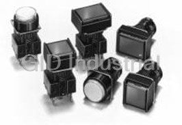
Switch Access Push Button Switch Square Button
A3DA-500Y
Part Number
A3DA-500Y
Price
Request Quote
Manufacturer
OMRON AUTOMATION
Lead Time
Request Quote
Category
Sensors and Transducers » Switch Accessories
Specifications
Manufacturer
Omron Automation
Manufacturers Part #
A3DA-500Y
Industry Aliases
A3DA-500Y
Sub-Categories
Switch Accessories
Factory Pack Quantity
1
Datasheet

Extracted Text
A3D Lighted Pushbutton Switch (Cylindrical 8-dia.) Lighted Pushbutton Switch with Cylindrical 18-mm × 8-dia. Body • Excellent illumination with even surface brightness. Cylindrical body means panel cutouts can be made easily. Combines miniature design with excellent operating sensitivity. RoHS Compliant A 3 Refer to Safety Precautions for All Pushbutton Switches/Indicators D and Safety Precautions on page 8. List of Models Appearance Model Rectangular A3DJ Square A3DA Round A3DT Model Number Legend ..... The model numbers used to order sets of Units are illustrated below. One set comprises the Pushbutton (LED lamp built-in) and Switch. For information on combinations, refer to Ordering Information. (1) (2) (3) A3D J -90 A 1-00E R (1) Shape of Pushbutton (2) Switch Specifications (3) Color of Pushbutton Microload (30 VDC, 0.1 A) Symbol Shape Symbol Color J Rectangular Symbol Terminals Operation Contact RRed A Momentary A Square Y Yellow Solder SPST-NO T Round B Alternate G Green Minimum applicable load: 1 mA at 5 VDC WWhite Standard load models are not available.All models are illumination only. If PCB terminals are required, use the Socket Colored-illumination models are not available. given under Accessories on page 3.Non-lighted models are not available. Momentary operation: Self-resettingAn external resistor is required. (Refer to page 8.) Alternate operation: Self-holding ■ Specifications: Refer to page 3. ■ Dimensions: Refer to page 6. ■ Accessories: Refer to page 3. ■ Precautions for correct use and safety precautions: Refer to page 8. 1 A3D Lighted Pushbutton Switch (Cylindrical 8-dia.) Ordering Information Ordering as a Set ................................. The model numbers used to order sets of Units are given in the following table. One set comprises the Pushbutton (LED lamp built-in), and Switch. Degree of Color symbol for Minimum Appearance Operation Model number protection Pushbutton packing unit A3DJ (Rectangular) Momentary A3DJ-90A1-00E@ 24.5 9.5 9 Alternate A3DJ-90B1-00E@ 14 A3DA (Square) Momentary A3DA-90A1-00E@ 24.5 A 9.5 3 IP40 R, Y, G, W 10 pcs D 9 Alternate A3DA-90B1-00E@ 9 A3DT (Round) Momentary A3DT-90A1-00E@ 24.5 9.5 Alternate A3DT-90B1-00E@ 9 dia. Note: 1. Enter the desired color symbol for the Pushbutton in @. 2. All the above are solder-terminal, microload, SPST-NO, LED lamp-lighted models. Ordering Individually ......................... Pushbuttons and Switches can be ordered separately. Combinations that are not available as sets can be created using individual Units. Ordering: Specify a model number from the following table. Appearance Rectangular Square Round Pushbutton (LED built-in) Minimum packing unit Color of pushbutton Red A3DJ-500R A3DA-500R A3DT-500R Yellow A3DJ-500Y A3DA-500Y A3DT-500Y 10 pcs Green A3DJ-500GY A3DA-500GY A3DT-500GY White A3DJ-500W A3DA-500W A3DT-500W Switch Sealing IP40 Appearance Rectangle Square Round Minimum packing unit Contact Operating Terminal type action type Solder Momentary A3DJ-7111 A3DA-7111 A3DT-7111 terminals SPST-NO 10 pcs Solder Alternate A3DJ-7121 A3DA-7121 A3DT-7121 terminals Ordering set combinations: Refer to this page. ■ Specifications: Refer to page 3. ■ Dimensions: Refer to page 6. ■ Accessories: Refer to page 3. 2 A3D Lighted Pushbutton Switch (Cylindrical 8-dia.) Ordering Information Accessories (Order Separately) Minimum Name Appearance Classification Model Remarks packing unit Wire-wrap terminal A3D-4101 Cannot be used together with Insula- Socket PCB terminal A3D-4102 tion Cover. 100 pcs Solder terminal A3D-4103 Cannot be used together with the Insulation Cover --- A3D-3002 Socket. A Do not tighten to a torque exceeding Tightening Tool --- A3D-3004 10 pcs 3 0.29 N·m. D Rectangular A3DJ-5201 One milky-white Legend Plate is in- Legend Plate Square A3DA-5201 100 pcs cluded with standard products. Round A3DT-5201 Specifications Ratings Characteristics Contact Rating: 30 VDC, 0.1 A (Minimum Applicable Load: 5 VDC, 1 mA) Momentary operation models: Note: Minimum allowable load: 5 VDC 1 mA (Resistive) 120 operations/minute max. The ratings given above are for testing under the following conditions: Mechanical Operating Alternate operation models: (1) Ambient temperature: 20 ± 2°C frequency 60 operations/minute max. *1 (2) Ambient humidity: 65 ± 5%RH (3) Operating frequency: 20 times/minute Electrical 20 operations/minute max. Contact resistance 100mΩ max. (initial value) Built-in LED Lamp (Ta=25°C) 100 MΩ min. Yellow Insulation resistance Color of LED Lamp Red Green (at 500 VDC with insulation tester) (White) *2 Between terminals of 1,000 VAC, 50/60 Hz for 1 min Reference same polarity 1.7 2.2 2.1 value (V) *1 Forward Between terminals of 2,000 VAC, 50/60 Hz for 1 min voltage, VF Maximum value different polarity Dielectric 2.0 2.5 2.5 (V) strength Between each terminal 2,000 VAC, 50/60 Hz for 1 min and ground Reference 20 20 20 value (mA) Between lamp ter- Forward 1,000 VAC, 50/60 Hz for 1 min *2 minals current, IF Absolute maximum 50 50 50 Vibration 10 to 55 Hz, 1.5 mm double value (mA) Malfunction resistance amplitude *3 Permissible 2 Absolute maximum Destruction 500 m/s max. Shock dissipation, 100 125 122 value (mW) 2 resistance PD Malfunction 150 m/s max. *3 Momentary operation models: Reverse Absolute maximum 444 1,000,000 operations min. voltage, VR value (V) Mechanical Alternate operation models: Durability Note: The built-in LED lamp has no limiting resistor and so it is necessary to 100,000 operations min. *1 connect an external resistor within the range shown in the above table. Electrical 100,000 operations min. (For details of calculation formulas, refer to page 8.) *1. Refer to Engineering Data on page 4. −10°C to +55°C Ambient operating temperature *2. The same LED lamp is used for both yellow illumination and white (with no icing or condensation) illumination and so the ratings are the same. Ambient operating humidity 35% to 85%RH −25°C to +65°C Ambient storage temperature (with no icing or condensation) Degree of protection IEC IP40 Weight Approx. 3 g Electric shock protection class Class II PTI (proof tracking index) 175 Pollution degree 3 (IEC60947-5-1) *1. With alternate operation models, one operation cycle consists of set and reset operations. *2. The figure is for when the LED lamp is not mounted. *3. Indicates malfunctions of less than 1 ms. 3 A3D Lighted Pushbutton Switch (Cylindrical 8-dia.) Specifications Operating Characteristics Contact Form Contact name Contact form Operating force OF max. 2.45 N Release force RF min. 0.196 N SPST-NO Total travel TT Approx. 3.5 mm COM NO Locktravel alternate * LTA min. 0.5 mm Pretravel PT max. 2.5 mm * Alternate operation models only. Engineering Data An external resistor is required. (Refer to page 8.) LED Characteristics (VF -IF Characteristics) A 3 Red LED Yellow or White LED Green LED D 100 100 100 Ta: Ambient Temperature Ta: Ambient Temperature Ta: Ambient Temperature 50 50 50 10 10 10 5 5 5 Ta=25°C Ta=25°C Ta=25°C Ta=50°C Ta=0°C Ta=50°C Ta=50°C Ta=0°C Ta=0°C 1 1 1 0.5 0.5 0.5 0.1 0.1 0.1 1.0 1.5 2.0 2.5 3.0 3.5 1.0 1.5 2.0 2.5 3.0 3.5 1.2 1.4 1.6 1.8 2.0 2.2 2.4 VF (V) VF (V) VF (V) Forward Current Reduction Curve 60 45mA 25°C 40 25mA 55°C 20 0 -10 0 10 20 30 40 50 60 TA (°C) 4 IF (mA) IF (mA) IF (mA) IF (mA) A3D Lighted Pushbutton Switch (Cylindrical 8-dia.) Nomenclature Model Structure Color cap (1) Shape of Pushbutton (2) Color of Pushbutton Legend plate (milky white) Pushbutton Reflective A plunger 3 D LED Switch (3) Switch Specifications Note: The A3DJ model is shown here as a representative example. Type Specifications Shape of Pushbutton Rectangular Square Round (A3DJ) (A3DA) (A3DT) ------ (1) LED-lighted (2) The LED lamp is built into the Pushbutton. Red, Yellow, Green, White 0.1 A at 30 VDC Microload (3) (Minimum applicable load: 1 mA at 5 VDC) 5 A3D Lighted Pushbutton Switch (Cylindrical 8-dia.) Dimensions (Unit: mm) Rectangular Models A3DJ 9.5 18 Panel Cutouts 0.8 (TOP VIEW) 6 5.8 +0.2 8 dia. 15 min. 0 4.8 0.4 M8 × 0.75 10 min. 0.3 1.6 9 7.4 5.5 12.4 24.5 Note: Recommended panel thickness: 1.0 to 3.2 mm. 14 Square Models A A3DA Panel Cutouts 9.5 18 3 (TOP VIEW) 0.8 6 D 5.8 10 min. +0.2 4.8 8 dia. 0 0.4 M8 × 0.75 0.3 1.6 Note: Recommended panel thickness: 1.0 to 3.2 mm. 9 7.4 5.5 7.4 24.5 9 Round Models A3DT Panel Cutouts 9.5 18 0.8 (TOP VIEW) 6 5.8 10 min. +0.2 4.8 8 dia. 0 0.4 M8 × 0.75 0.3 1.6 Note: Recommended panel thickness: 1.0 to 3.2 mm. 9 dia.7.4 dia. 5.5 24.5 If the panel is to be finished (e.g., coated), make sure that the panel meets the specified dimensions after the coating. Terminals Type SPST-NO Lighted Models Terminals Terminal Arrangement 0.8 (Bottom View) 6.5 t0.4 L- Solder Terminals 0.8×2 LED terminal (t0.3) CNO 1.6 L+ 2 0.8 0.8 6 A3D Lighted Pushbutton Switch (Cylindrical 8-dia.) Dimensions (Unit: mm) Accessory Mounting Dimensions Socket Mounting Dimensions Wire-wrap Terminal/A3D-4101 PCB Terminal/A3D-4102 Solder Terminal/A3D-4103 1 5 3.5 30.7 16.5 30.7 30.7 16.5 16.5 16.5 0.3 0.3 1.9 0.6 1.6 6.1 9 dia. 1 9 dia. 6.1 9 dia. 1.6 1.9 0.3 0.3 1.9 1 0.6 6.1 1.6 6.1 1.6 1.9 PCB Cutout A (BOTTOM VIEW) 3 D 6.5 Four, 0.8 dia. 6.5 Insulation Cover Mounting Dimensions (The illustration shows the rectangular model as a representative example.) • After securing the Switch to the panel using the mounting nut, pass A3D-3002 the lead wires through the holes in the Insulation Cover before 31 performing wiring. Hold the Insulation Cover so that the cylindrical 18 hole is facing the Switch, and insert the lead wires from the end with the barriers. 8.9 dia. • After wiring is completed, mount the Insulation Cover by pushing it into the Switch. Note: Unless specified, there is a tolerance of ± 0.4 mm for dimensions. Legend Plate Mounting Dimensions Rectangular/A3DJ-5201 Square/A3DA-5201 Round/A3DT-5201 0.8 5.3 5.8 5.8 10.7 5.8 5.8 dia. Note: 1. The thickness is 0.8 mm. 2. Since the legend plate is made of polycarbonate, use alcohol-based paints such as melanin, phthalic acid, or acrylic paint when marking the legend. 7 A3D Lighted Pushbutton Switch (Cylindrical 8-dia.) Safety Precautions Refer to Safety Precautions for All Pushbutton Switches/Indicators. Precautions for Correct Use Mounting Calculation Example for Limiting Resistance • Always make sure that the power is turned OFF before mounting, LED lamp illuminating color: Red removing, or wiring the Switch, or performing maintenance. Electric E = 24V shock or fire may occur. IF = 20mA • Do not tighten the mounting ring excessively using pliers or a Ta = 25°C similar tool. Excessive tightening may damage the mounting ring. The VF-IF characteristics (for red) on page 4 yield the following: (Tightening torque: 0.20 to 0.29 N·m) VF = 1.7 V when IF = 20 mA. Therefore, inserting the values into the formula above (R = E − VF/IF(Ω)): Wiring R = 24 (V) − 1.7 (V)/0.02 (A) ≅ 1100 (Ω). 2 The recommended resistance is 1.1 kΩ at 1 W (2 × IF R). • When wiring, use wires of a size appropriate for the applied voltage Note: Approximately twice this value is appropriate to provide a and carry current. Perform soldering correctly under the conditions A margin in the capacity of the resistor. given below. Using the Switch with the wires soldered incorrectly 3 may cause the terminals to become abnormally hot and cause a D Operating Environment fire. 1. Hand soldering: • Ensure that dust, metal powder, or oil do not enter the interior of the Soldering iron tip temperature: 350°C max. within 3 seconds. Switch. 2. Dip soldering: At 350°C within 3 seconds. Using Microloads Wait for one minute after soldering before exerting any external force on the solder. • Using a standard load switch for opening and closing a microload • Use a non-corrosive rosin liquid for the flux. circuit may cause wear on the contacts. Use the switch within the • Perform wiring so that the wire sheaths do not come into contact operating range. (Refer to the diagram below.) Even when using with the Switch. If this is unavoidable, use wires that can withstand microload models within the operating range shown below, if inrush temperatures of 100°C min. current occurs when the contact is opened or closed, it may cause After wiring to the Switch has been completed, ensure an the contact surface to become rough, and so decrease life appropriate insulation distance. expectancy. Therefore, insert a contact protection circuit where necessary. LED The minimum applicable load is the N-level reference value. This • The polarity of the LED is indicated on the back of the Switch. Wire value indicates the malfunction reference level for the reliability the LED correctly according to the polarity. level of 60% (λ 60) (conforming to JIS C5003). The equation, −6 • The built-in LED does not have a limiting resistor. Connect a limiting λ 60 = 0.5 x 10 /times indicates that the estimated malfunction rate resistor. is less than 1/2,000,000 with a reliability level of 60%. • Make sure that the limiting resistor satisfies the characteristics of the built-in LED. The forward current of the built-in LED must be 8 mA minimum. 0.15mA 26mA 100mA 30 • The resistance can be calculated by using the following expression. E-VF E : Operating voltage (V) R=------------ (Ω) F I VF : LED forward voltage (V) 24 IF : LED forward current (A) Standard Microload area load area Recommended Values for Limiting Resistance Voltage Red Yellow (White) Green 12 Invalid 5 VDC 165 Ω 140 Ω 145 Ω area 5 12 VDC 515 Ω 490 Ω 495 Ω 1mA 100mA 150mA 24 VDC 1,100 Ω 1,090 Ω 1,095 Ω 0 0.1 1 10 100 1,000 Note: The above values are calculated values that can be used as reference. Current (mA) 8 Voltage (V) A3D Lighted Pushbutton Switch (Cylindrical 8-dia.) Application Mounting and Replacing the Pushbutton Socket Mounting • After securing the Switch to the panel using the mounting nut, insert (1) Mounting Direction for the Pushbutton and Switch the Socket into the Switch. • When inserting the Socket, align the positioning groove of the Socket with the projecting part of the Switch. Curved claw Projection (Switch) (Pushbutton) Panel • Align the curved claw on the outside of the protruding part of the Pushbutton with the projection on the upper part of the Switch and insert. • Apply a pressure between 9.8 and 24.5 N. Projecting part of Switch • If the terminals of the LED lamp become bent, it may be impossible to fit them into the LED lamp terminal holes. Ensure that the Positioning groove of Socket terminals are straight when they are inserted. A Be sure to insert the lamp terminals for round models (A3DT or 3 M2DT) with the correct orientation. Inserting the terminals with the D reverse orientation will result in damage. (2) Removing the Pushbutton Recessed portions • Hold the recessed portions on the cap of the Pushbutton and pull. • Do not use tools such as pliers to remove the Pushbutton as this may damage the cap. Panel Mounting Using the Mounting Nut • Insert the Switch from the front of the panel. Mount the mounting nut from the terminal end of the Switch and tighten it. • Tighten the nut to a torque 0.20 to 0.29 N·m. • If soldering is used, mount the mounting nut first. Lead wires and mounds of solder may make it impossible to mount the nut after soldering. Mounting nut Panel 9 A3D Lighted Pushbutton Switch (Cylindrical 8-dia.) A 3 D Application examples provided in this document are for reference only. In actual applications, confirm equipment functions and safety before using the product. Consult your OMRON representative before using the product under conditions which are not described in the manual or applying the product to nuclear control systems, railroad systems, aviation systems, vehicles, combustion systems, medical equipment, amusement machines, safety equipment, and other systems or equipment that may have a serious influence on lives and property if used improperly. Make sure that the ratings and performance characteristics of the product provide a margin of safety for the system or equipment, and be sure to provide the system or equipment with double safety mechanisms. Note: Do not use this document to operate the Unit. OMRON Corporation Electronic and Mechanical Components Company Contact: www.omron.com/ecb Cat. No. A031-E1-07 1014(0207)(O) 10
Frequently asked questions
How does Electronics Finder differ from its competitors?

Is there a warranty for the A3DA-500Y?
Which carrier will Electronics Finder use to ship my parts?
Can I buy parts from Electronics Finder if I am outside the USA?
Which payment methods does Electronics Finder accept?
Why buy from GID?

Quality
We are industry veterans who take pride in our work

Protection
Avoid the dangers of risky trading in the gray market

Access
Our network of suppliers is ready and at your disposal

Savings
Maintain legacy systems to prevent costly downtime

Speed
Time is of the essence, and we are respectful of yours
Related Products
Switch Access Safety Interlock Switch Cord Grip
Switch Access Safety Interlock Switch Stainless Steel Alignment Guide
Switch Access Push Button Switch Solder Terminal A16-1
Switch Access Push Button Switch LED A16-12DSG
Switch Access Push Button Switch LED A16-12DSW
Switch Access Push Button Switch LED A16-12DSY
Request a Quote

The quote request has been received
Close

Facing challenges or have inquiries? Feel free to contact us!
Call Us +1-469-283-2440
What they say about us
FANTASTIC RESOURCE
One of our top priorities is maintaining our business with precision, and we are constantly looking for affiliates that can help us achieve our goal. With the aid of GID Industrial, our obsolete product management has never been more efficient. They have been a great resource to our company, and have quickly become a go-to supplier on our list!
Bucher Emhart Glass
EXCELLENT SERVICE
With our strict fundamentals and high expectations, we were surprised when we came across GID Industrial and their competitive pricing. When we approached them with our issue, they were incredibly confident in being able to provide us with a seamless solution at the best price for us. GID Industrial quickly understood our needs and provided us with excellent service, as well as fully tested product to ensure what we received would be the right fit for our company.
Fuji
HARD TO FIND A BETTER PROVIDER
Our company provides services to aid in the manufacture of technological products, such as semiconductors and flat panel displays, and often searching for distributors of obsolete product we require can waste time and money. Finding GID Industrial proved to be a great asset to our company, with cost effective solutions and superior knowledge on all of their materials, it’d be hard to find a better provider of obsolete or hard to find products.
Applied Materials
CONSISTENTLY DELIVERS QUALITY SOLUTIONS
Over the years, the equipment used in our company becomes discontinued, but they’re still of great use to us and our customers. Once these products are no longer available through the manufacturer, finding a reliable, quick supplier is a necessity, and luckily for us, GID Industrial has provided the most trustworthy, quality solutions to our obsolete component needs.
Nidec Vamco
TERRIFIC RESOURCE
This company has been a terrific help to us (I work for Trican Well Service) in sourcing the Micron Ram Memory we needed for our Siemens computers. Great service! And great pricing! I know when the product is shipping and when it will arrive, all the way through the ordering process.
Trican Well Service
GO TO SOURCE
When I can't find an obsolete part, I first call GID and they'll come up with my parts every time. Great customer service and follow up as well. Scott emails me from time to time to touch base and see if we're having trouble finding something.....which is often with our 25 yr old equipment.
ConAgra Foods