

 Manufacturers
OMRON AUTOMATION D4A1106N
Description
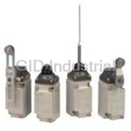
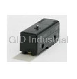
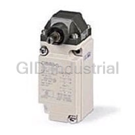
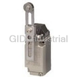
Switch Limit N.O./N.C. SPDT Side Plunger Conduit 10A 600VAC 250VDC Linear Screw Mount
D4A1106N
Part Number
D4A1106N
Price
Request Quote
Manufacturer
OMRON AUTOMATION
Lead Time
Request Quote
Category
Switches » Switch Limit
Specifications
Manufacturer
Omron Automation
Manufacturers Part #
D4A1106N
Industry Aliases
D4A-1106N
Sub-Category
Limit Switches
Factory Pack Quantity
1
Datasheet

Extracted Text
General-purpose Limit Switch D4A-@N CSM_D4A-_N_DS_E_4_2 The Limit Switch with Better Seal, Shock Resistance, and Strength • A double seal on the head, a complete gasket cover, and other features ensure a better seal (meets UL NEMA 3, 4, 4X, 6P, 12, 13). • Wide standard operating temperature range: −40°C to +100°C (standard type). • Models with fluoro-rubber available for greater resistance to chemicals. • Block mounting method also reduces downtime for maintenance. • DPDT, double-break models available for complex operations. For the most recent information on models that have been certified for • Approved by UL, CSA, and CCC (Chinese standard). safety standards, refer to your OMRON website. (Ask your OMRON representative for information on approved model.) Be sure to read Safety Precautions on page 14 to 15 and Safety Precautions for All Limit Switches. Model Number Structure Model Number Legend (Not all combinations are possible. Ask your OMRON representative for details.) D4A-@@@@N (Set model number) (1) (2) (3) (1) Receptacle box (3) Head 1 : 1/2-14 NPT conduit (SPDT, double-break) 01 : Roller lever, standard 2 : 1/2-14 NPT conduit (DPDT, double-break) 02 : Roller lever, high-sensitivity 3 : G 1/2 conduit (SPDT, double-break) 03 : Roller lever, low torque 4 : G 1/2 conduit (DPDT, double-break) 04 : Roller lever, high-sensitivity, low torque 05 : Roller lever, maintained (2) Switch Box 17 : Roller lever, sequential operation 1 : SPDT, double-break, without indicator 18 : Roller lever, center neutral operation 3 : SPDT, double-break, neon lamp 06 : Side plunger, standard E : SPDT, double-break, LED (24 VDC, leakage current: 1.3 mA) 07-V : Side plunger, vertical roller 5 : DPDT, double-break, simultaneous operation, without indicator 07-H : Side plunger, horizontal roller 7 : DPDT, double-break, sequential operation, without indicator *1 08 : Side plunger, adjustable 9 : DPDT, double-break, center neutral operation, without indicator *2 09 : Top plunger, standard L : DPDT, double-break, simultaneous operation, neon lamp 10 : Top plunger, roller P : DPDT, double-break, simultaneous operation, LED 11 : Top plunger, adjustable 12 : Flexible rod, spring wire 14 : Flexible rod, plastic rod 15 : Flexible rod, cat whisker 16 : Flexible rod, coil spring *1. Use the D4A-0017N Special Head. *2. Use the D4A-0018N Special Head. Note: Fluoro-rubber sealed type is also available. 1 D4A-@N Ordering Information Set model number SPDT, Double-break Switches Receptacle box G 1/2 Conduit Indicator Without indicator With neon lamp indicator (AC) With LED indicator (DC) Approved Approved Model Model Model standards standards Actuator Standard D4A-3101N UL, CSA D4A-3301N UL, CSA D4A-3E01N High-sensitivity D4A-3102N UL, CSA D4A-3302N UL, CSA D4A-3E02N Roller lever *1 Low-torque D4A-3103N UL, CSA --- --- --- High-sensitivity, D4A-3104N UL, CSA D4A-3304N UL, CSA --- Low-torque Maintained *2 D4A-3105N UL, CSA D4A-3305N UL, CSA D4A-3E05N Standard D4A-3106N UL, CSA --- --- --- Vertical roller D4A-3107-VN UL, CSA D4A-3307-VN UL, CSA D4A-3E07-VN Side plunger Horizontal roller D4A-3107-HN UL, CSA D4A-3307-HN UL, CSA --- Adjustable D4A-3108N UL, CSA D4A-3308N UL, CSA D4A-3E08N Standard D4A-3109N UL, CSA D4A-3309N UL, CSA --- Top plunger Roller D4A-3110N UL, CSA D4A-3310N UL, CSA --- Adjustable D4A-3111N UL, CSA D4A-3311N UL, CSA --- Spring wire D4A-3112N UL, CSA D4A-3312N UL, CSA D4A-3E12N Plastic rod D4A-3114N UL, CSA D4A-3314N UL, CSA D4A-3E14N Flexible rod Cat whisker D4A-3115N UL, CSA D4A-3315N UL, CSA D4A-3E15N Coil spring D4A-3116N UL, CSA D4A-3316N UL, CSA D4A-3E16N Note: 1. Switches are also available with @1/2-14 NPT conduits. The model numbers correspond as follows: (Examples) G 1/2 Conduits 1/2-14 NPT Conduits D4A-3@@@N D4A-1@@@N D4A-4@@@N D4A-2@@@N 2. Switches are also available with fluoro-rubber seals for higher resistance to chemicals. (The operating temperature range for these Switches, however, is −10 to +120°C.) Add “-F” to the model number. (Example: D4A-3101N becomes D4A-3101N-F.) Ask your nearest OMRON representative for details. *1. The lever is not included with the Roller Level Models. Select the lever from those listed in this data sheet and order it separately (refer to Levers on page 12). *2. The Maintained Switches have a lock mechanism for the switch operation and thus use a Fork Lever Lock. 2 D4A-@N DPDT, Double-break Switches Receptacle box G 1/2 Conduit Indicator Without indicator With neon lamp indicator (AC) With LED indicator (DC) Actuator Model Approved standards Model Model Standard D4A-4501N UL, CSA D4A-4L01N D4A-4P01N High-sensitivity D4A-4502N UL, CSA --- --- Low-torque D4A-4503N UL, CSA --- --- High-sensitivity, Roller lever *1 D4A-4504N UL, CSA --- --- Low-torque Maintained *2 D4A-4505N UL, CSA --- --- Sequential operation D4A-4717N UL, CSA --- --- Center neutral D4A-4918N UL, CSA --- --- operation Standard D4A-4506N UL, CSA --- --- Vertical roller D4A-4507-VN UL, CSA --- --- Side plunger Horizontal roller D4A-4507-HN UL, CSA --- --- Adjustable D4A-4508N UL, CSA --- --- Standard D4A-4509N UL, CSA --- --- Top plunger Roller D4A-4510N UL, CSA D4A-4L10N D4A-4P10N Adjustable D4A-4511N UL, CSA --- --- Spring wire D4A-4512N UL, CSA --- --- Plastic rod D4A-4514N UL, CSA --- --- Flexible rod Cat whisker D4A-4515N UL, CSA --- --- Coil spring D4A-4516N UL, CSA --- --- Note: 1. Switches are also available with @1/2-14 NPT conduits. The model numbers correspond as follows: (Examples) G 1/2 Conduits 1/2-14 NPT Conduits D4A-3@@@N D4A-1@@@N D4A-4@@@N D4A-2@@@N 2. Switches are also available with fluoro-rubber seals for higher resistance to chemicals. (The operating temperature range for these Switches, however, is −10 to +120°C.) Add “-F” to the model number. (Example: D4A-4501N becomes D4A-4501N-F.) Ask your nearest OMRON representative about delivery times and prices. *1. The lever is not included with the Roller Level Models. Select the lever from those listed in this data sheet and order it separately (refer to Levers on page 12). *2. The Maintained Switches have a lock mechanism for the switch operation and thus use a Fork Lever Lock. Individual Parts Receptacle box Type G1/2 conduit *1 1/2-14NPT conduit *2 Appearance Model Approved standards Model Approved standards SPDT dou- D4A-3000N UL, CSA D4A-1000N UL, CSA ble-break DPDT dou- D4A-4000N UL, CSA D4A-2000N UL, CSA *1. M6-screw mounting ble-break (standard mounting) *2. 10-32UNF-screw mounting (standard mounting) 3 D4A-@N Switch Box With LED Indicator Without indicator With neon lamp indicator (AC) indicator (DC) Approved Approved Appearance Model Model Model standards standards SPDT double- D4A-0100N UL, CSA D4A-0300N UL, CSA D4A-0E00N break (Without indicator lamp) Simultaneous D4A-0500N UL, CSA D4A-0L00N --- D4A-0P00N operation Sequential DPDT double- D4A-0700N UL, CSA --- --- --- operation break Center neutral D4A-0900N UL, CSA --- --- --- operation (Without indicator lamp) Heads Approved Approved Model Model standards standards Appearance Appearance Type Standard D4A-0001N UL, CSA High-sensitivity D4A-0002N UL, CSA Standard D4A-0009N UL, CSA Low-torque *2 D4A-0003N UL, CSA Sequential oper- D4A-0017N UL, CSA ation: *3 Center neutral D4A-0018N UL, CSA operation: *3 Roller D4A-0010N UL, CSA Maintained D4A-0005N UL, CSA Adjustable D4A-0011N UL, CSA Standard D4A-0006N UL, CSA Vertical roller D4A-0007-VN UL, CSA Spring wire D4A-0012N UL, CSA Horizontal roller D4A-0007-HN UL, CSA Side adjustable D4A-0008N UL, CSA *1. Levers for Roller Lever Switches are optionally available. Select the lever from those listed in this data sheet and order (refer to Levers on page 12). Plastic rod D4A-0014N UL, CSA *2. The D4A-C00 adjustable roller lever is too heavy and long for these heads and it should not be used or mechanical malfunction will result. *3. These heads cannot be used for double break operations. Cat whisker D4A-0015N UL, CSA Coil spring D4A-0016N UL, CSA 4 Side plunger Roller lever *1 Flexible rod Top plunger D4A-@N Levers Actuator Model D4A-A00 D4A-A10 Roller Lever D4A-A20 D4A-A30 D4A-B06 D4A-C00 Adjustable Roller Lever D4A-D00 Resin Loop Lever D4A-F00 D4A-E30 D4A-E20 Fork Lever Lock D4A-E10 D4A-E00 Note: Refer to page 12 for Lever shapes and applicable models. Specifications Approved Standards Agency Standard File No. UL UL508 E76675 CSA CSA C22.2 No.14 LR45746 CCC (CQC) GB14048.5 2003010305077615 Note: Ask your OMRON representative for information on approved models. Ratings for Indicators Ratings Non-inductive load (A) Inductive load (A) Classi- Rated Leakage Internal Indicator Model fication voltage current resistance Rated Resistive Inductive Type Lamp load Motor load voltage load load 125 VAC, Approx. Neon lamp D4A-0300N 150 kΩ SPDT 250 VAC 0.47 mA NC NO NC NO NC NO NC NO double- Approx. 125 VAC * 10 10 3 1.5 10 5 2.5 break LED D4A-0E00N 24 VDC 15 kΩ 1.3 mA 250 VAC * 10 10 2 1 10 3 1.5 SPDT 480 VAC 1.5 0.8 3 1.5 0.8 125 VAC, Approx. 10 10 Neon lamp D4A-0L00N 240 kΩ DPDT double- 600 VAC 1 0.5 1.5 1 0.5 250 VAC 0.28 mA 3 1 double- break Approx. 8 VDC 10 6 3 10 6 break (with/ LED D4A-0P00N 48 VDC --- 1.4 mA 14 VDC 10 6 3 10 6 without 30 VDC 6 4 3 6 4 indicator) 125 VDC * 0.8 0.2 0.2 0.8 0.2 250 VDC * 0.4 0.1 0.1 0.4 0.1 125 VAC 5 2 4 3 250 VAC 3 1 2 1.5 DPDT 480 VAC 1.5 0.5 1 0.8 double- 600 VAC 1 0.4 0.7 0.5 break 14 VDC 5 2 4 3 (without 30 VDC 3 1 2 1.5 indicator) 125 VDC 0.4 0.1 0.4 0.1 250 VAC 0.2 0.05 0.2 0.05 125 VAC 5 2 4 3 DPDT 250 VAC 3 1 2 1.5 double- break 12 VDC 5 (with in- 24 VDC 3 --- --- --- --- dicator) 48 VDC 1 * For those with indicators, refer to the following rated voltages. SPDT, Double-break DPDT, Double-break Item Type Without With indi- Without With indi- indicator cator indicator cator Normally closed 30 A max. Inrush current Normally open 20 A max. Note: 1. The above current ratings are for steady-state current. 2. Inductive loads have a power factor of 0.4 min. (AC) and a time constant of 7 ms max. (DC). 3. Lamp loads have an inrush current of 10 times the steady-state current. 4. Motor loads have an inrush current of 6 times the steady-state current. 5 D4A-@N Approved Standard Ratings Characteristics UL/CSA Degree of protection IP67 and NEMA 1, 2, 3, 4X, 5, 6P, 12, (reference standards) and 13 A600 SPDT, double-break, roller lever: D4A-@1@@N (SPDT, Double-break, Without Indicator) 50,000,000 operations min. Mechanical: *1 DPDT, double-break, roller lever: Current (A) Volt-amperes (VA) Rated Carry 30,000,000 operations min. voltage current Make Break Make Break Durability SPDT, double-break: for 125 VAC, *2 120 VAC 60 6 10 A resistive load: 1,000,000 opera- 240 VAC 30 3 Electrical: tions min. 10 A 7,200 720 480 VAC 15 1.5 DPDT, double-break: for 125 VAC, 5 A 600 VAC 12 1.2 resistive load: 750,000 operations min. 1 mm/s to 2 m/s (in case of D4A-3101N Operating speed A300 roller lever model) D4A-@3@@N (SPDT, Double-break, With Neon Lamp) Mechanical: 300 operations/minute Operating frequency Electrical: 30 operations/minute Current (A) Volt-amperes (VA) Rated Carry Rated frequency 50/60 Hz voltage current Make Break Make Break 100 MΩ min. (at 500 VDC) between 120 VAC 60 6 10 A 7,200 720 terminals of the same polarity, be- 240 VAC 30 3 Insulation resistance tween current-carrying metal parts and ground, and between each terminal B600 and non-current-carrying metal part D4A-@5@@N (DPDT, Double-break, Simultaneous Contact resistance 25 mΩ max. (initial value) Operation) Temperature rise 50°C max. D4A-@7@@N (DPDT, Double-break, Sequential Operation) Between terminals of 1,000 VAC, 50/60 Hz for 1 min. same polarity D4A-@9@@N (DPDT, Double-break, Center Neutral Between current-car- Operation) Dielectric rying metal parts and 2,200 VAC, 50/60 Hz for 1 min. *3 strength ground Current (A) Volt-amperes (VA) Rated Carry Between each termi- voltage current Make Break Make Break nal and non-current- 2,200 VAC, 50/60 Hz for 1 min. *3 120 VAC 30 3 carrying metal part 240 VAC 15 1.5 5 A 3,600 360 Pollution degree 480 VAC 7.5 0.75 3 (operating environment) 600 VAC 6.0 0.6 Protection against electric shock Class I (with grounding terminal) CCC (GB14048.5) Vibration Malfunction: *4 10 to 55 Hz, 1.5-mm double amplitude resistance Applicable category and ratings 2 Destruction: 1,000 m/s max. AC-15 2 A/125 VAC SPDT, double-break, roller lever: Shock re- 2 600 m/s max. sistance Malfunction: *4 DPDT, double-break, roller lever: 2 300 m/s max. Ambient operating humidity 35% to 95%RH (with no icing) Weight Approx. 290 g (in case of D4A-3101N) Note: The above figures are initial values. *1. Excluding maintained models. *2. The values are calculated at an operating temperature of +5°C to +35°C, and an operating humidity of 40% to 70%RH. Contact your OMRON sales representative for more detailed information on other operating environments. *3. 1,500 VAC is applied to the indicator lamp type. *4. Not including Flexible rods (cat whisker, plastic rod, coil spring, and spring wire types). Plunger, flexi- Item Type Roller lever *1 With indicator ble rod *2 Ambient tempera- −40°C to +100°C −20°C to +100°C −10°C to +80°C ture *1. Excluding low-torque and high-sensitivity models. *2. Including roller lever low-torque and high-sensitivity operating models. 6 D4A-@N Engineering Data Electrical Durability (SPDT Double-break) (Ambient temperature: +5°C to +35°C; ambient humidity: 40% to 70%RH) 500 500 125 VAC Operating frequencies: Operating frequencies: 300 30 operations/min, 300 30 operations/min, cosφ = 1 125 VAC cosφ = 1 250 VAC 250 VAC 480 VAC 100 100 480 VAC 50 50 30 30 10 10 0 2 4 6 8 10 12 0 2 4 6 8 10 12 Switching current (A) Switching current (A) Electrical Durability (DPDT Double-break) 500 500 Operating frequencies: Operating frequencies: 300 300 30 operations/min, 30 operations/min, cosφ = 1 125 VAC cosφ = 1 125 VAC 250 VAC 100 100 250 VAC 480 VAC 50 50 480 VAC 30 30 10 10 0 0 12 3 4 5 6 12 3 4 5 6 Switching current (A) Switching current (A) Structure and Nomenclature Structure (DPDT Double-break) Head Easy-maintenance Block Mounting Roller With the Roller Lever and Side Plunger Switches, the Block mounting makes it possible to easily assemble The roller actuator is made of hardened direction of the switch head can be varied to any of the four stainless steel and excels in resistance to or disassemble the head, switch body, and directions by loosing the roller lever switch screws at the wear. receptacle of the D4A-@N by tightening or loosening four corners of the head. the attached screws. Lever The Roller Lever Switch With the Roller Lever Switch, the lever can Head employs a system which be installed anywhere in a 360° range (180° allows selection of the if the lever is reversed and attached to operation of only one side the shaft). (left or right) or both sides without use of any tools. Oil Seal Improved sealing property is ensured with a Operating Position double-seal construction (a oil seal plus an X-ring seal). Mark (arrow) Actuator Bearings The copper-alloy bearings ensure long life Switch Box expectancy. Boasts long life expectancy (50 million mechanical operations or more with the 2-pole Double-break Switches and Receptacle 30 million mechanical operations or more The plug-in type receptacle provides adequate with the DPDT Double-break Switches). Switch space for wiring. box Ground Terminal Screw A ground terminal is provided to enhance safety. Conduit Opening *1, *2 Receptacle Switch Box Screw G 1/2 conduit threads featuring high sealing A Phillips screw is used to secure the switch Sealed Gasket property are used. (Refer to Limit Switch housing for ease of use, and features a The employed full-cover Connectors for details on SC connectors). measure to prevent the screw from coming off. method prevents the gasket A terminal box with 1/2-14NPT conduit threads from direct exposure to oil is also available on request. or water spray. Note: 1. NBR is used in rubber components. Fluoro-rubber sealed types use fluoro-rubber. 2. For Roller Levers, there is some lever play in the free position (about 2 mm), but this is due to the structure of the head and does not interfere with performance. *1. A Receptacle and Terminal Box with 1/2-14NPT conduit threads are also available for the North America market. *2. The conduit thread indication has been changed from “PF1/2” to “G1/2” accompanying the JIS B 0202 revision. This changes applies only to the indication; thread sizes and pitches have not been affected. 7 4 4 Durability (x 10 operations) Durability (x 10 operations) 4 4 Durability (x 10 operations) Durability (x 10 operations) D4A-@N Contact Forms (Switch Boxes) STDP Double-break Switches Contact model Type Operating pattern Without indicator With neon lamp indicator * With LED indicator * D4A-0100N D4A-0300N D4A-0E00N Lamp Lamp unit unit Za Za Za 4 3 4 3 4 3 1 2 1 2 1 2 Energized 1NC/1NO Lamp Lamp unit unit 1-2 snap-action 3-4 Lamp Unit Internal Circuits Lamp Unit Internal Circuits Neon lamp LEDs Rectifier stack Resistor Resistor * Switches with indicators are factory-set to light when the switch is not operated. DTDP Double-break Switches Each of these Switches can be used to replace two limit switches in applications, such as high-speed control in machine tools and switching motors between forward and reverse, that previously required 2 limit switches. This simplifies wiring, saves space, and reduces costs. Contact model Type Operating pattern Remarks With neon lamp Without indicator With LED indicator * indicator * Energized Head is compatible with 1-2 2NC/2NO snap-action, double-break head. Can 3-4 D4A-0500N D4A-0L00N D4A-0P00N simultaneous operation be switched for operation 5-6 on both sides of actuator. 7-8 Stroke Energized 1-2 2NC/2NO snap-action, Use the D4A-0017N Spe- 3-4 sequential operation D4A-0700N --- --- cial Head. 5-6 (2-step operation) 7-8 Stroke Energized 1-2 3-4 2NC/2NO snap-action, Use the D4A-0018N Spe- 5-6 central neutral opera- D4A-0900N --- --- cial Head. 7-8 tion Left Free Right operation position operation Item Without indicator With neon lamp indicator * With LED indicator * D4A-0500N D4A-0L00N D4A-0P00N D4A-0700N D4A-0900N Za Lamp Lamp Lamp Lamp 4 3 unit unit unit unit Contact Za Za Za Za form 1 2 4 3 8 7 4 3 8 7 8 7 1 2 5 6 1 2 5 6 Lamp Lamp Lamp Lamp unit unit unit unit 5 6 Constant Rectifier stack current diode Neon lamp Lamp unit internal ---- Resistor circuit LED * Switches with indicators are factory-set to light when the switch is not operated, but the setting can be changed to light for operation (dotted lines). 8 D4A-@N Dimensions and Operating Characteristics (Unit: mm) Set Model Numbers (The box in a model number indicates the switch box type.) Roller Lever Switches Note: Levers of the side rotary type are optionally available. Standard 62.5 D4A-3@01N, D4A-4@01N 48 Four, M4 (length: 12) 21 screws for head 7.25 dia. High-sensitivity 24.5 34 D4A-3@02N, D4A-4@02N 19 +0.2 Low-torque 5.2 dia. 0 mounting holes D4A-3@03N, D4A-4@03N 75.5 R2.6 59.5±0.2 70.5 High-sensitivity/Low-torque 6 0.8 D4A-3@04N, D4A-4@04N Two, M6 R2.6 5.2 Two, M5 (length: 20) 16.5 (depth: 10) screws for screws for box back-mounting 28 Sequential Operation 29.4±0.2 G1/2 42 29.5 D4A-4@17N conduit 44 Center Neutral Operating D4A-4@18N Maintained 62 D4A-3@05N, D4A-4@05N 47.5 Four, M4 (length: 12) 21 screws for head 7.25 dia. 38.1 19.1 +0.2 5.2 dia. 0 mounting holes 75.5 R2.6 70.5 59.5±0.2 6 0.8 Two, M6 R2.6 5.2 (depth: 10) screws for Two, M5 (length: 20) 16.5 back-mounting screws for box 28 29.4±0.2 42 G1/2 29.5 conduit 44 Note: Unless otherwise specified, a tolerance of ±0.4 mm applies to all dimensions. Model SPDT Double-break DPDT Double-break D4A- D4A- D4A- D4A- D4A- D4A- D4A- D4A- D4A- D4A- D4A- D4A- Operating characteristics 3@01N 3@02N 3@03N 3@04N 3@05N 4@01N 4@02N 4@03N 4@04N 4@05N 4@17N 4@18N Operating force OF max. 0.39 N·m 0.39 N·m 0.2 N·m 0.2 N·m 0.39 N·m 0.39 N·m 0.39 N·m 0.2 N·m 0.2 N·m 0.39 N·m 0.39 N·m 0.39 N·m Release force RF min. 0.05 N·m 0.05 N·m --- --- --- 0.05 N·m 0.05 N·m --- --- --- 0.05 N·m 0.02 N·m 1-stage: 12° (10°) Pretravel PT max. 15° (12°) 7° (6°) 15° (12°) 7° (6°) 65° (60°) 15° (12°) 7° (6°) 15° (12°) 7° (6°) 65° (60°) 19° (15°) 2-stage: 20° (17°) Overtravel OT min. 70° 75° 70° 75° 20° 70° 75° 70° 75° 20° 65° 65° Movement Differential 5° (4°) 4° (3°) 5° (4°) 4° (3°) 35° (30°) 7° (6°) 5° (4°) 7° (6°) 5° (4°) 35° (30°) 6° (5°) 5° (4°) MD max. Note: The figures in the parentheses are average values. 9 D4A-@N Side Plunger Switches Standard Horizontal Roller Stainless Four, M4 (length: 12) Four, M4 (length: 12) PT steel plunger D4A-3@06N D4A-3@07-HN screws for head PT OP 21 screws for head OP 21 D4A-4@06N D4A-4@07-HN 21.5 21.5 10 dia. 31.1 31.1 19 19 11 dia.x 5 +0.2 stainless +0.2 5.2 dia. 5.2 dia. 0 0 steel roller mounting mounting holes holes 75.5 75.5 R2.6 70.5 R2.6 59.5±0.2 70.5 59.5±0.2 6 6 0.8 0.8 16.5 Two, M6 Two, M6 R2.6 5.2 R2.6 5.2 Two, M5 (length: 20) Two, M5 (length: 20) (depth: 10) screws 16.5 (depth: 10) screws 28 screws for box screws for box for back-mounting for back-mounting 28 29.4±0.2 29.4±0.2 29.5 42 42 29.5 G1/2 G1/2 44 44 conduit conduit M5 x 0.8 (length:14) Vertical Roller Adjustable Allen-head bolt Four, M4 (length: 12) Four, M4 (length: 12) PT OP 21 D4A-3@07-VN screws for head D4A-3@08N screws for head PT OP 21 D4A-4@07-VN D4A-4@08N 21.5 21.5 31.1 31.1 19 19 11 dia.x 5 +0.2 stainless 5.2 dia. +0.2 0 5.2 dia. 0 steel roller mounting mounting holes 75.5 holes 75.5 R2.6 59.5±0.2 70.5 R2.6 59.5±0.2 70.5 6 6 0.8 0.8 Two, M6 R2.6 5.2 Two, M6 R2.6 5.2 Two, M5 (length: 20) (depth: 10) screws Two, M5 (length: 20) 16.5 16.5 (depth: 10) screws screws for box for back-mounting screws for box 28 29.4±0.2 for back-mounting 28 29.4±0.2 42 29.5 G1/2 42 G1/2 29.5 44 conduit 44 conduit Model SPDT Double-break DPDT Double-break Operating characteristics D4A-3@06N D4A-3@07-HN D4A-3@07-VN D4A-3@08N D4A-4@06N D4A-4@07-HN D4A-4@07-VN D4A-4@08N Operating force OF max. 19.61 N 19.61 N 19.61 N 19.61 N 19.61 N 19.61 N 19.61 N 19.61 N Release force RF min. 4.90 N 4.90 N 4.90 N 4.90 N 4.90 N 4.90 N 4.90 N 4.90 N Pretravel PT max. 2.4 mm 2.4 mm 2.4 mm 2.4 mm 2.4 mm 2.4 mm 2.4 mm 2.4 mm Overtravel OT min. 5.1 mm 5.1 mm 5.1 mm 5.1 mm 5.1 mm 5.1 mm 5.1 mm 5.1 mm Movement Differential 0.6 mm 0.6 mm 0.6 mm 0.6 mm 1.0 mm 1.0 mm 1.0 mm 1.0 mm MD max. OP * 34±0.8 mm 44±0.8 mm 44±0.8 mm 41 to 47.5 mm 34±0.8mm 44±0.8 mm 44±0.8 mm 41 to 47.5 mm * Operating position Top Plunger Switches 10 dia. Stainless steel plunger 11 dia.x 5 stainless Standard Roller Plunger PT 21 steel roller 21 D4A-3@09N D4A-3@10N PT Four, M4 (length: 12) D4A-4@09N D4A-4@10N Four, M4 (length: 12) screws for head screws for head 27 OP OP 27 +0.2 5.2 dia. 0 mounting +0.2 5.2 dia. holes 0 75.5 mounting R2.6 70.5 59.5±0.2 holes 75.5 R2.6 59.5±0.2 70.5 6 0.8 6 R2.6 5.2 Two, M6 0.8 Two, M5 (length: 20) 16.5 (depth: 10) screws Two, M6 R2.6 5.2 screws for box 28 for back-mounting 29.4±0.2 Two, M5 (length: 20) 16.5 (depth: 10) screws screws for box 42 for back-mounting 29.5 28 G1/2 29.4±0.2 44 conduit 42 29.5 G1/2 44 conduit M5 x 0.8 (length:14) Adjustable Model SPDT double-break DPDT double-break Allen-head bolt PT 21 D4A-3@11N Operating D4A D4A D4A D4A D4A D4A D4A-4@11N character- -3@09N -3@10N -3@11N -4@09N -4@10N -4@11N Four, M4 (length: 12) istics screws for head OF max. 17.65 N 17.65 N 17.65 N 17.65 N 17.65 N 17.65 N OP 27 RF min. 4.90 N 4.90 N 4.90 N 4.90 N 4.90 N 4.90 N PT max. 1.6 mm 1.6 mm 1.6 mm 1.6 mm 1.6 mm 1.6 mm +0.2 5.2 dia. 0 OT min. 5.1 mm 5.1 mm 5.1 mm 5.1 mm 5.1 mm 5.1 mm mounting holes MD max. 0.4 mm 0.4 mm 0.4 mm 1.0 mm 1.0 mm 1.0 mm 75.5 R2.6 59.5±0.2 70.5 46±0.8 56±0.8 55.5 to 46±0.8 56±0.8 55.5 to OP * mm mm 62 mm mm mm 62 mm 6 0.8 * Operating position Two, M6 R2.6 5.2 Two, M5 (length: 20) (depth: 10) screws 16.5 screws for box for back-mounting 28 29.4±0.2 G1/2 42 29.5 conduit 44 Note: A Fork Lever Lock can be used with D4A-@@05N models only. 10 D4A-@N Flexible Rod Spring wire Plastic Rod (see note 1) (see note 1) D4A-3@12N 8 dia. max. D4A-3@14N PT 1.8 dia. D4A-4@12N D4A-4@14N 7 dia. PT Stainless steel (see note 2) wire rod (see note 2) Plastic rod (287) (106.5) Four, M4 (length: 12) 21 21 Four, M4 (length: 12) screws for head 150 screws for head 330 88.5 88 27 27 +0.2 +0.2 5.2 dia. 0 5.2 dia. 0 mounting mounting holes 75.5 holes 75.5 R2.6 59.5±0.2 70.5 R2.6 70.5 59.5±0.2 6 6 0.8 0.8 16.5 R2.6 Two, M6 Two, M6 5.2 R2.6 Two, M5 (length: 20) 5.2 16.5 Two, M5 (length: 20) (depth: 10) screws for (depth: 10) screws for screws for box 28 screws for box back-mounting back-mounting 28 29.4±0.2 29.4±0.2 29.5 42 29.5 G1/2 42 G1/2 44 44 conduit conduit Note: 1. The stainless rod can be operated from any direction except the Note: 1. The plastic rod can be operated from any direction except the axial direction (i.e., from the top). axial direction (i.e., from the top). 2. The optimum operating range of the stainless rod is within 1/3 2. The optimum operating range of the plastic rod is within 1/3 of the entire length from the top end. of the entire length from the top end. Cat Whisker Coil Spring (see note 1) (see note 1) D4A-3@15N D4A-3@16N 1.4 dia. PT D4A-4@15N D4A-4@16N (see note 2) Stainless steel PT 6.5 dia. Stainless steel wire rod coil spring (see note 2) (124) (106.5) Four, M4 (length: 12) 21 screws for head 21 Four, M4 (length: 12) 170.5 screws for head 150 93.5 27 27 +0.2 +0.2 5.2 dia. 0 5.2 dia. 0 mounting mounting holes holes 75.5 75.5 R2.6 59.5±0.2 70.5 R2.6 59.5±0.2 70.5 6 6 0.8 0.8 R2.6 Two, M6 Two, M6 5.2 R2.6 5.2 Two, M5 (length: 20) Two, M5 (length: 20) 16.5 16.5 (depth: 10) screws (depth: 10) screws screws for box screws for box for back-mounting 28 for back-mounting 28 29.4±0.2 29.4±0.2 42 42 29.5 G1/2 29.5 G1/2 44 44 conduit conduit Note: 1. The coil spring rod can be operated from any direction except the Note: 1. The stainless rod can be operated from any direction except the axial direction (i.e., from the top). axial direction (i.e., from the top). 2. The optimum operating range of the coil spring rod is within 1/3 2. The optimum operating range of the stainless rod is within 1/3 of the entire length from the top end. of the entire length from the top end. Note: Unless otherwise specified, a tolerance of ±0.4 mm applies to all dimensions. Model SPDT Double-break DPDT Double-break Operating characteristics D4A-3@12N D4A-3@14N D4A-3@15N D4A-3@16N D4A-4@12N D4A-4@14N D4A-4@15N D4A-4@16N Operating force OF max. 0.98 N 1.47 N 0.98 N 1.47 N Pretravel PT max. 15° (5°) 15° (5°) 15° (5°) 15° (5°) Note: The figures in the parentheses are average values. 11 D4A-@N Levers (for Roller Lever Switches) Note: No D4A-0003N or D4A-0004N head should be used with the adjustable roller lever or mechanical malfunctioning could result because the total weight of the adjustable roller lever is comparatively large. Use a standard-load head (D4A-0001N or D4A-0002N) instead. Roller Lever Roller Lever Fork Lever Lock D4A-A00 D4A-B06 D4A-E30 Note: A Fork Lever 11.5 19 dia. Lock can be 21 7.9 17.5 dia. Stainless Stainless used with sintered roller 15 sintered 17 D4A-@@05N (2) roller 7.9 models only. 3.6 Stainless sintered 38.1 roller 7.3 dia. 33.7 7.3 dia. 19 dia. 90° 38.1 7.3 dia. 18 9 18 9 M5 Allen bolt M5 Allen bolt Roller Lever Adjustable Roller Lever Stainless M5 Allen bolt sintered 9 38.1 D4A-A10 D4A-C00 roller 19.5 19 dia. 19 dia. 7.9 Stainless Stainless 7.9 14 Fork Lever Lock sintered roller sintered roller D4A-E20 Note: A Fork Lever 6.4 graduation Lock can be used with 38.1 7.3 dia. D4A-@@05N 17 models only. (2) 33 to 91 3.6 Stainless 7.9 (adjustable) sintered 7.3 dia. roller 90° 19 dia. 113 18 9 M5 Allen bolt 38.1 7.3 dia. M5 Allen bolt Roller Lever 4.5 D4A-A20 Stainless 19 dia. sintered 7.9 M5 Allen bolt Stainless 12.9 9 38.1 roller sintered roller 2.5 18 21.2 Fork Lever Lock 38.1 7.3 dia. D4A-E10 Note: A Fork Lever Adjustable Rod Lever Lock can be used with D4A-D00 26 D4A-@@05N 20 22 (2) models only. 3 dia. 6.2 7.9 18 9 16.5 10.5 M5 Allen bolt Stainless 3.6 Stainless rod sintered roller 90° 19 dia. Roller Lever D4A-A30 150 max. 38.1 7.3 dia. (adjustable) 13 19 dia. 7.9 Stainless 7.3 dia. 160 sintered roller Stainless M5 Allen bolt sintered 9 38.1 roller 38.1 7.3 dia. M5 Allen bolt 4.5 Fork Lever Lock D4A-E00 Note: A Fork Lever 7.5 Lock can be 18 9 M5 Allen bolt 21.2 used with 39.4 26 D4A-@@05N 22 models only. (2) 6.2 7.9 Nylon Loop Lever Stainless 3.6 150±10 sintered D4A-F00 roller 7.3 dia. 90° 19 dia. 60±10 (23.6) 38.1 6 11 7.3 dia. 7.5 M5 Allen bolt 25 max. 13.8 4 dia. Nylon Stainless 5.5 33 sintered M5 Allen bolt 9 38.1 M5 Allen bolt roller Note: Unless otherwise specified, a tolerance of ±0.4 mm applies to all dimensions. 12 D4A-@N Head and Lever Positions • The operating head can be positioned Remove the head from the The operating head can be The lever can lock in any position through 360° around and locked in any of four 90° positions Switch by loosening the screws positioned and locked in the shaft. The lever can be reversed and attached to the (the screws can be loosened any of four 90° positions. shaft, in which case the switching operation should and a lever can lock in any position but not removed from the head). complete in a range of 0° to 180°. through 360° around the shaft of the Limit 180° operating Switch. Furthermore, the lever can be position reversed and attached to the shaft (refer to the figures below on the right hand side). Therefore the roller is compatible with a wide movement range of a dog. • A Fork Lever Lock can be used with maintained models (D4A-0005N) only. 360° operating position Four, M4 x 12 D4A-E00 D4A-E10 There are four kinds of fork lever locks. The position of each roller is different. It is possible to use D4A-E00 through D4A-E30 levers instead, if they are reversed before attaching. They can be used with D4A-@@05N models only. D4A-E20 D4A-E30 By loosening the Allen-head bolt on an adjustable roller lever or rod lever, the length of the lever can be adjusted. D4A-C00 D4A-D00 Loosen the screw D4A-D00 Loosen to adjust the the bolt to adjust Adjustable between length of the rod. the length of the 33 and 91 mm lever. Lever Position D4A-A00 D4A-A10 D4A-A20 D4A-A30 59 to 64.5 67 to 72.5 73 to 78.5 86.9 to 92.4 52.9 to 58.4 25 to 30.5 44.9 to 50.4 38.9 to 44.4 Nameplate Compatibility with D4A-@ The D4A-@N is compatible with the D4A-@ when the following accessories are attached to the D4A-@N. The whole switch model without lever is printed. The type of switch box is printed. (The type is also indicated on the head and receptacle.) D4A-@ D4A-@N D4A-@N Receptacle box Switch box Head When ordering, do not confuse set model numbers and model numbers for individual blocks. The D4A-@N without the above accessories is not compatible with the D4A-@. 13 D4A-@N Safety Precautions Refer to Safety Precautions for All Limit Switches. Precautions for Correct Use Operating Environment Lighting Mode Selection of Indicators (SPDT only) • Seal material may deteriorate if a Switch is used outdoor or where The lighting mode of the operation indicator can be changed easily subject to special cutting oils, solvents, or chemicals. Always between two modes: lighting when the Switch is operating and lighting when the Switch is not operating. appraise performance under actual application conditions and set suitable maintenance and replacement periods. Lights When Not Operating *1 Lights When Operating *2 • Install Switches where they will not be directly subject to cutting chips, dust, or dirt. The Actuator and Switch must also be protected from the accumulation of cutting chips or sludge. Not Suitable Suitable Power supply Power supply Built-in switch Internal circuits 4 3 4 3 Load • Constantly subjecting a Switch to vibration or shock can result in 1 2 Load wear, which can lead to contact interference with contacts, 2 1 operation failure, reduced durability, and other problems. Excessive vibration or shock can lead to false contact operation or Built-in switch Internal circuits damage. *1. The lamp is lit when the actuator is at the free position. Install Switches in locations not subject to shock and vibration and The lamp will be off when the contacts of the Limit Switch have been in orientations that will not produce resonance. actuated and snapped to each other at the operating position. • The Switches have physical contacts. Using them in environments *2. The lamp is lit when the contacts have been released and snapped only from the operating position. containing silicon gas will result in the formation of silicon oxide (SiO2) due to arc energy. If silicon oxide accumulates on the Change the lighting mode as follows: contacts, contact interference can occur. If silicon oil, silicon filling 1. Push the claw securing 2. Remove the lamp 3. Mount the lamp section agents, silicon cables, or other silicon products are present near the the lamp section to the section. so that legend “NC-ON” Switch, suppress arcing with contact protective circuits (surge right (do not push or “NO-ON” will appear killers) or remove the source of silicon gas. strongly). in the display window. Changing the Operating Direction Roller Lever Switch The head of the side rotary type can be converted in seconds to CW, CCW, or both-way operation. Follow the procedures on the right hand side for conversion (not applicable to the Maintained, Sequential Operating, Center Neutral Operating Switches). Operating Part (Rear of Head) Procedures 1. Dismount the head by loosening the Operating position arrow marks In either case, the lamp will not light when the load is ON. four screws that secure it. 2. Turn over the head to set the desired Mounting operation (CW, CCW, or both). The desired side can be selected by set- G1/2 Conduit ting the mode selector knob shown in Mounting lo- Model D4A-3@@@N the figure. This knob is factory set to cations D4A-4@@@N the “CW+CCW” (both-way operation) +0.2 position. Two, 5.2 dia. holes 0 or M5 tapped holes 3. When set to the CW position, the head rotates in clockwise direction. When set to the CCW position, the head rotates in counterclockwise di- rection. Front 59.5±0.15 In either case, be sure to accurately Mounting align the arrow mark to the setting po- sition. : Mounting locations 29.4±0.15 +0.2 Two, 6.2 dia. holes 0 (Recommended mounting screws: M6. Switch Box depth: 10.) Rear 59.5±0.15 Mounting : Mounting locations 29.4±0.15 14 D4A-@N Screw Tightening Torques for Heads and Switch Boxes Appropriate Tightening Torque To maintain the high sealing capability of the Limit Switch, tighten the A loose screw may cause malfunctions. Be sure to tighten each screw screws for the head and switch box with the following torques: to the proper tightening torque as shown in the table. Head (four 12-mm M4 screws): 1.2 to 1.4 N·m Switch box (two 20-mm M5 screws): 2.4 to 2.7 N·m Solderless Terminals The D4A-@N with DPDT double-break incorporates solderless terminals. Operation • The operating methods, cam and dog shapes, operating frequency, and overtravel (OT) have a significant effect on the service life and accuracy of the Limit Switch. The shape of the cam should be as smooth as possible. • A marginal overtravel (OT) value should be set. The ideal value is the rated OT value x 0.7. • The actuator should not be remodeled to change the operating position. Connectors To satisfy IP67, apply sealing tape to the connector conduit. Appropriate external diameter of cables is 5.5 to 14 dia. Use OMRON’s SC-@M Series. Tighten the Connectors to a torque of 1.8 to 2.2 N·m. Maintenance and Repair Appropriate tightening The user must not maintain or repair equipment incorporating any No. Type torque D4A-N model. Contact the manufacturer of the equipment for any Terminal screws (M3.5 screws) (in- maintenance or repairs required. 0.78 to 0.88 N·m 1 cluding grounding terminals) Head mounting screws 1.18 to 1.37 N·m 2 3 Switch box mounting screws 2.35 to 2.75 N·m Body mounting screws 4.90 to 5.88 N·m 4* 5 Connectors 1.77 to 2.16 N·m Actuator mounting screws 2.45 to 2.65 N·m 6 * When using M5 Allen-head bolts, particularly when the head direction has been changed, check the torque of each screw and make sure that the screws are free of foreign substances, and that each screw is tightened to the proper torque. How to Order The D4A-@N is compatible with the D4A-@ Individual model numbers when the following accessories are attached to the D4A-@N. = Receptacle Switch box Lever Set model numbers Head * = Example: D4A- 3101N D4A- 3 000N D4A-0 1 00N D4A-00 01 N D4A-A00 *The D4A-@N without the above accessories is not compatible with the D4A-@. 15 Read and Understand This Catalog Please read and understand this catalog before purchasing the products. Please consult your OMRON representative if you have any questions or comments. Warranty and Limitations of Liability WARRANTY OMRON's exclusive warranty is that the products are free from defects in materials and workmanship for a period of one year (or other period if specified) from date of sale by OMRON. OMRON MAKES NO WARRANTY OR REPRESENTATION, EXPRESS OR IMPLIED, REGARDING NON-INFRINGEMENT, MERCHANTABILITY, OR FITNESS FOR PARTICULAR PURPOSE OF THE PRODUCTS. ANY BUYER OR USER ACKNOWLEDGES THAT THE BUYER OR USER ALONE HAS DETERMINED THAT THE PRODUCTS WILL SUITABLY MEET THE REQUIREMENTS OF THEIR INTENDED USE. OMRON DISCLAIMS ALL OTHER WARRANTIES, EXPRESS OR IMPLIED. LIMITATIONS OF LIABILITY OMRON SHALL NOT BE RESPONSIBLE FOR SPECIAL, INDIRECT, OR CONSEQUENTIAL DAMAGES, LOSS OF PROFITS OR COMMERCIAL LOSS IN ANY WAY CONNECTED WITH THE PRODUCTS, WHETHER SUCH CLAIM IS BASED ON CONTRACT, WARRANTY, NEGLIGENCE, OR STRICT LIABILITY. In no event shall the responsibility of OMRON for any act exceed the individual price of the product on which liability is asserted. IN NO EVENT SHALL OMRON BE RESPONSIBLE FOR WARRANTY, REPAIR, OR OTHER CLAIMS REGARDING THE PRODUCTS UNLESS OMRON'S ANALYSIS CONFIRMS THAT THE PRODUCTS WERE PROPERLY HANDLED, STORED, INSTALLED, AND MAINTAINED AND NOT SUBJECT TO CONTAMINATION, ABUSE, MISUSE, OR INAPPROPRIATE MODIFICATION OR REPAIR. Application Considerations SUITABILITY FOR USE OMRON shall not be responsible for conformity with any standards, codes, or regulations that apply to the combination of products in the customer's application or use of the products. At the customer's request, OMRON will provide applicable third party certification documents identifying ratings and limitations of use that apply to the products. This information by itself is not sufficient for a complete determination of the suitability of the products in combination with the end product, machine, system, or other application or use. The following are some examples of applications for which particular attention must be given. This is not intended to be an exhaustive list of all possible uses of the products, nor is it intended to imply that the uses listed may be suitable for the products: Outdoor use, uses involving potential chemical contamination or electrical interference, or conditions or uses not described in this catalog. Nuclear energy control systems, combustion systems, railroad systems, aviation systems, medical equipment, amusement machines, vehicles, safety equipment, and installations subject to separate industry or government regulations. Systems, machines, and equipment that could present a risk to life or property. Please know and observe all prohibitions of use applicable to the products. NEVER USE THE PRODUCTS FOR AN APPLICATION INVOLVING SERIOUS RISK TO LIFE OR PROPERTY WITHOUT ENSURING THAT THE SYSTEM AS A WHOLE HAS BEEN DESIGNED TO ADDRESS THE RISKS, AND THAT THE OMRON PRODUCTS ARE PROPERLY RATED AND INSTALLED FOR THE INTENDED USE WITHIN THE OVERALL EQUIPMENT OR SYSTEM. PROGRAMMABLE PRODUCTS OMRON shall not be responsible for the user's programming of a programmable product, or any consequence thereof. Disclaimers CHANGE IN SPECIFICATIONS Product specifications and accessories may be changed at any time based on improvements and other reasons. It is our practice to change model numbers when published ratings or features are changed, or when significant construction changes are made. However, some specifications of the products may be changed without any notice. When in doubt, special model numbers may be assigned to fix or establish key specifications for your application on your request. Please consult with your OMRON representative at any time to confirm actual specifications of purchased products. DIMENSIONS AND WEIGHTS Dimensions and weights are nominal and are not to be used for manufacturing purposes, even when tolerances are shown. PERFORMANCE DATA Performance data given in this catalog is provided as a guide for the user in determining suitability and does not constitute a warranty. It may represent the result of OMRON’s test conditions, and the users must correlate it to actual application requirements. Actual performance is subject to the OMRON Warranty and Limitations of Liability. ERRORS AND OMISSIONS The information in this document has been carefully checked and is believed to be accurate; however, no responsibility is assumed for clerical, typographical, or proofreading errors, or omissions. 2012.9 In the interest of product improvement, specifications are subject to change without notice. OMRON Corporation Industrial Automation Company http://www.ia.omron.com/ (c)Copyright OMRON Corporation 2012 All Right Reserved.
Frequently asked questions
How does Electronics Finder differ from its competitors?

Is there a warranty for the D4A1106N?
Which carrier will Electronics Finder use to ship my parts?
Can I buy parts from Electronics Finder if I am outside the USA?
Which payment methods does Electronics Finder accept?
Why buy from GID?

Quality
We are industry veterans who take pride in our work

Protection
Avoid the dangers of risky trading in the gray market

Access
Our network of suppliers is ready and at your disposal

Savings
Maintain legacy systems to prevent costly downtime

Speed
Time is of the essence, and we are respectful of yours
Related Products
Basic / Snap Action Switches BASIC SWITCH A-20GV-C-K
Switch Limit N.O./N.C. SPDT Side Roller Lever Conduit 10A 600VAC 250VDC Rotary Screw Mount D4A-1101-...
Switch Limit N.O./N.C. SPDT Side Roller Lever Conduit 10A 600VAC 250VDC Rotary Screw Mount D4A1101NF
Switch Limit N.O./N.C. SPDT Side Roller Lever Conduit 10A 600VAC 250VDC Rotary Screw Mount D4A-1102-...
Switch Limit N.O./N.C. SPDT Side Roller Lever Conduit 10A 600VAC 250VDC Rotary Screw Mount D4A-1103-...
Switch Limit N.O./N.C. SPDT Side Roller Lever Conduit 10A 600VAC 250VDC Rotary Screw Mount D4A-1104-...
Request a Quote

The quote request has been received
Close

Facing challenges or have inquiries? Feel free to contact us!
Call Us +1-469-283-2440
What they say about us
FANTASTIC RESOURCE
One of our top priorities is maintaining our business with precision, and we are constantly looking for affiliates that can help us achieve our goal. With the aid of GID Industrial, our obsolete product management has never been more efficient. They have been a great resource to our company, and have quickly become a go-to supplier on our list!
Bucher Emhart Glass
EXCELLENT SERVICE
With our strict fundamentals and high expectations, we were surprised when we came across GID Industrial and their competitive pricing. When we approached them with our issue, they were incredibly confident in being able to provide us with a seamless solution at the best price for us. GID Industrial quickly understood our needs and provided us with excellent service, as well as fully tested product to ensure what we received would be the right fit for our company.
Fuji
HARD TO FIND A BETTER PROVIDER
Our company provides services to aid in the manufacture of technological products, such as semiconductors and flat panel displays, and often searching for distributors of obsolete product we require can waste time and money. Finding GID Industrial proved to be a great asset to our company, with cost effective solutions and superior knowledge on all of their materials, it’d be hard to find a better provider of obsolete or hard to find products.
Applied Materials
CONSISTENTLY DELIVERS QUALITY SOLUTIONS
Over the years, the equipment used in our company becomes discontinued, but they’re still of great use to us and our customers. Once these products are no longer available through the manufacturer, finding a reliable, quick supplier is a necessity, and luckily for us, GID Industrial has provided the most trustworthy, quality solutions to our obsolete component needs.
Nidec Vamco
TERRIFIC RESOURCE
This company has been a terrific help to us (I work for Trican Well Service) in sourcing the Micron Ram Memory we needed for our Siemens computers. Great service! And great pricing! I know when the product is shipping and when it will arrive, all the way through the ordering process.
Trican Well Service
GO TO SOURCE
When I can't find an obsolete part, I first call GID and they'll come up with my parts every time. Great customer service and follow up as well. Scott emails me from time to time to touch base and see if we're having trouble finding something.....which is often with our 25 yr old equipment.
ConAgra Foods