

 Manufacturers
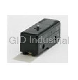
OMRON AUTOMATION D4F-302-1D

Description
Switch Limit N.O./N.C. SP4T Top Roller Plunger Cable 0.75A 240VAC 250VDC 12N Linear Screw Mount
D4F-302-1D
Part Number
D4F-302-1D
Price
Request Quote
Manufacturer
OMRON AUTOMATION
Lead Time
Request Quote
Category
Switches » Switch Limit
Specifications
Manufacturer
Omron Automation
Manufacturers Part #
D4F-302-1D
Industry Aliases
D4F-302-1D
Sub-Category
Limit Switches
Factory Pack Quantity
1
Datasheet

Extracted Text
Small Safety Limit Switch D4F CSM_D4F_DS_E_5_2 Note: Contact your sales representative for details on Smallest Class of Safety Limit Switches in models with safety standard certification. the World • The world's smallest limit switch with a direct opening mechanism (four-contact construction model). High-sensitivity safety limit switch. Built-in switches with two- or four-contact construction are available. Degree of protection: IP67 Conforms to EN115-1, EN81-1 and EN81-2. (slow-action models only) Certified standards: UL, EN (TÜV), and CCC Be sure to read the “Safety Precautions” on page 6 and the “Precautions for All Safety Limit Switches” . For the most recent information on models that have been certified for safety standards, refer to your OMRON website. Model Number Structure Model Number Legend D4F-@@-@@ 12 3 4 1. Built-in Switch 3. Cable Length 1: 1NC/1NO (slow-action) 1: 1 m 2: 2NC (slow-action) 3: 3 m 3: 2NC/2NO (slow-action) 5: 5 m 4: 4NC (slow-action) 4. Pull-outing direction of cable R: Horizontal 2. Actuator 02: Roller plunger D: Vertical (Metal roller) 20: Roller lever (Metal lever, resin roller) Ordering Information List of Models Safety Limit Switches (with Direct Opening Mechanism) Consult with your OMRON representative when ordering any models that are not listed in this table. Built-in switch 1NC/1NO 2NC 2NC/2NO 4NC Cable Pull-outing Actuator (slow-action) (slow-action) (slow-action) (slow-action) length direction of cable Direct Direct Direct Direct Model Model Model Model opening opening opening opening Horizontal D4F-120-1R D4F-220-1R D4F-320-1R D4F-420-1R 1 m Roller lever Vertical D4F-120-1D D4F-220-1D D4F-320-1D D4F-420-1D (Metal lever, Horizontal D4F-120-3R D4F-220-3R D4F-320-3R D4F-420-3R resin roller) 3 m Vertical D4F-120-3D D4F-220-3D D4F-320-3D D4F-420-3D Horizontal D4F-120-5R D4F-220-5R D4F-320-5R D4F-420-5R 5 m Vertical D4F-120-5D D4F-220-5D D4F-320-5D D4F-420-5D Horizontal D4F-102-1R D4F-202-1R D4F-302-1R D4F-402-1R Roller 1 m plunger Vertical D4F-102-1D D4F-202-1D D4F-302-1D D4F-402-1D (Metal roller) Horizontal D4F-102-3R D4F-202-3R D4F-302-3R D4F-402-3R 3 m Vertical D4F-102-3D D4F-202-3D D4F-302-3D D4F-402-3D Horizontal D4F-102-5R D4F-202-5R D4F-302-5R D4F-402-5R 5 m Vertical D4F-102-5D D4F-202-5D D4F-302-5D D4F-402-5D 1 D4F Specifications Standards and EC Directives Certified Standard Ratings Conforms to the following EC Directives: TÜV (EN60947-5-1), CCC (GB14048.5) • Machinery Directive Item Utilization category AC-15 DC-13 • Low Voltage Directive Rated operating current (Ie) 0.75 A 0.27 A • EN50047 Rated operating voltage (Ue) 240 V 250 V • EN60204-1 • EN ISO 14119 Note: Use a 10 A fuse type gI or gG that conforms to IEC60269 as a • GS-ET-15 short-circuit protection device. Certified Standards UL/CSA (UL508, CSA C22.2 No. 14) C300 Certification body Standards File No. EN60947-5-1 Current (A) Volt-amperes (VA) Rated TÜV SÜD *1 Carry current (certified direct opening) voltage Make Break Make Break UL508 120 VAC 15 1.5 UL *2 E76675 CSA C22.2 No.14 2.5 A 1,800 180 240 VAC 7.5 0.75 20030103050 CQC (CCC) *3 GB14048.5 64266 Q300 *1. Contact your OMRON sales representative. Current (A) Volt-amperes (VA) Rated *2. Certification has been obtained for CSA C22.2 No. 14 under UL. Carry current voltage Make Break Make Break *3. Ask your OMRON representative for information on certified models. 125 VDC 0.55 0.55 2.5 A 69 69 250 VDC 0.27 0.27 2 D4F Characteristics Degree of protection *1 IP67 (EN60947-5-1) Mechanical 10,000,000 times min. Durability *2 1,000,000 times min. (4 mA resistive load at 24 VDC, 4 circuits) Electrical 150,000 times min. (1 A resistive load at 125 VAC, 2 circuits/4 mA resistive load at 24 VDC, 2 circuits) *3 Operating speed 1 mm/s to 0.5 m/s Mechanical 120 operations/minute Operating frequency Electrical 30 operations/minute Contact resistance *5 300 mΩ max. (with 1 m cable), 500 mΩ max. (with 3 m cable), 700 mΩ max. (with 5 m cable) Minimum applicable load *4 4 mA resistive load at 24 VDC, 4 circuits (N-level reference value) Rated insulation voltage (Ui) 250 V Rated frequency 50/60 Hz Protection against electric shock Class I (with a ground wire) Pollution degree (operating environment) 3 (EN60947-5-1) Between terminals 2.5 kV of same polarity Impulse withstand Between terminals 4 kV voltage (EN60947-5-1) of different polarity Between each 4 kV terminal and ground 100 MΩ min. (at 500 VDC) between terminals of the same polarities, between terminals of different polarities, Insulation resistance between current-carrying metal parts and grounds, and between each terminal and non-current carrying metal parts Contact gap 2 × 2 mm min. Vibration resistance Malfunction 10 to 55 Hz, 0.75 mm single amplitude 2 Destruction 1,000 m/s min. Shock resistance 2 Malfunction 300 m/s min. Conditional short-circuit current 100 A (EN60947-5-1) Conventional free air thermal current (Ith) 2.5 A (EN60947-5-1) Ambient operating temperature −30 to 70°C (with no icing) Ambient operating humidity 95% max. Cable UL2464 No. 22 AWG, finishing O.D.: 8.3 mm Approx. 190 g (D4F-102-1R, with 1 m cable) Weight Approx. 220 g (D4F-120-1R, with 1 m cable) Note: 1. The above values are initial values. 2. Once the contact is opened or closed with an ordinary load, it cannot be used for a load smaller than that. The contact surface may be rough, which impairs the reliability of contacting. *1. The degree of protection shown above is based on the test method specified in EN60947-5-1. Be sure to confirm in advance the sealing performance under the actual operating environment and conditions. *2. Durability values are calculated at an operating temperature of 5 to 35°C, and an operating humidity of 40% to 70%. Contact your OMRON sales representative for more detailed information on other operating environments. *3. Do not apply 1 A at 125 VAC to more than two circuits. *4. The value will vary depending on factors such as the switching frequency, the ambient environment, and the reliability level. Be sure to confirm correct operation with the actual load before application. *5. The contact resistance was measured with 0.1 A at 5 to 8 VDC with a fall-of-potential method. 3 D4F Structure and Nomenclature Structure Head Lever The plunger type of actuator can be used in a Improved safety of the lever-setting (Form lock configuration). normal direction and reverse direction. Many grooves are incised on the lever and the rotating shaft that mesh with each other to prevent a slip between the lever and the rotating shaft. The lever can be set for positioning in steps of 9 degrees. Cable The cable can be pulled out in a horizontal Built-in Switch direction or in a vertical direction. Has a direct opening mechanism separating the contacts when the NC contacts are welded. Direct Opening Mechanism 1NC/1NO Contact (slow-action) Fixed contact (NC) Contact spring Movable contact Fixed contact (NO) Return spring Plunger Conforms to EN60947-5-1 Direct Opening . (Only the NC contacts have a direct opening function.) When contact welding occurs, the NC contacts are separated from each other by pushing in the plunger. Contact Form Model Contact Contact form Operating pattern Remarks Only NC contact 11-12 has a certified Zb 11-12 direct opening mechanism. 1NC/1NO ON 11 12 D4F-1@-@@ 33-34 (slow-action) 33 34 The terminals 11-12 and 33-34 can be Stroke used as unlike poles. NC contacts 11-12 and 21-22 have a Zb certified direct opening mechanism. 11-12 2NC ON 11 12 D4F-2@-@@ 21-22 (slow-action) The terminals 11-12 and 21-22 can be 21 22 Stroke used as unlike poles. Zb 11-12 NC contacts 11-12 and 21-22 have a 11 12 21-22 certified direct opening mechanism. 2NC/2NO 21 22 D4F-3@-@@ 33-34 ON (slow-action) The terminals 11-12, 21-22, 33-34 and 33 34 43-44 43-44 can be used as unlike poles. Stroke 43 44 NC contacts 11-12, 21-22, 31-32 and 41- Zb 11-12 11 12 42 have a certified direct opening 21-22 4NC mechanism. 21 22 D4F-4@-@@ 31-32 (slow-action) ON 31 32 41-42 The terminals 11-12, 21-22, 31-32 and Stroke 41 42 41-42 can be used as unlike poles. Note: The terminal numbers are according to EN 50013 and the contact symbols are according to EN 60947-5-1. 4 D4F Dimensions and Operating Characteristics (Unit: mm) Roller lever (Metal lever, resin roller) Roller plunger (Metal roller) D4F-@20-@R (30.8) D4F-@02-@R 25.5 9 17.5-dia. × 6.8, resin roller Pretravel 12-dia. × 4.4, Sintered stainless steel roller 24.7R Operating Two, 4.4-dia. 30 Two, 4.4-dia. position 8-dia. countersinking, 27.5 8-dia. countersinking, 18.5 depth 4 8.8 depth 4 (14.4-dia.) (14.4-dia.) 0.1 20± 0.1 (35) 20± (35) (42.7) (42.7) 30 18 18 30 (11.4) UL2464 (11.4) UL2464 No. 22 AWG, No. 22 AWG, finishing O.D.: 8.3 mm finishing O.D.: 8.3 mm Roller lever (Metal lever, resin roller) Roller plunger (Metal roller) (30.8) D4F-@20-@D D4F-@02-@D 25.5 17.5-dia. × 6.8, 9 resin roller Pretravel 12-dia. × 4.4, Sintered stainless steel roller 24.7R Operating Two, 4.4-dia. 30 Two, 4.4-dia. position 8-dia. countersinking, 27.5 8-dia. countersinking, 18.5 depth 4 8.8 depth 4 ±0.1 20 0.1 20± (42.7) (42.7) (16.7) (16.7) (7.9) (7.9) UL2464 UL2464 No. 22 AWG, No. 22 AWG, finishing O.D.: 8.3 mm finishing O.D.: 8.3 mm (17.6) 18 18 (17.6) 30 2 30 2 Note: Each dimension has a tolerance of 0.4 mm unless otherwise specified. Slow-action (1NC/1NO), (2NC), (2NC/2NO), and (4NC) Model D4F-@20-@R D4F-@02-@R Operating Characteristics D4F-@20-@D D4F-@02-@D Operating force OF max. *1 5 N 12 N Release force RF min. *2 0.5 N 1.5 N Pretravel PT1 (11-12 and 21-22) 6±3° (NC) 1 mm max. (NC) PT1 (31-32 and 41-42) 9±3° (NC) 1.3 mm max. (NC) PT2 *3 (12°) (NO) (1.2 mm) (NO) Overtravel OT min. 40° 3.2 mm Operating position OP (11-12 and 21-22) --- 29.4±1 mm OP (31-32 and 41-42) --- 29±1 mm Total travel TT *3 (55°) (4.5 mm) Direct opening travel DOT min. *4 18° 1.8 mm Direct opening force DOF min. 20 N 20 N Note: Variation occurs in the simultaneity of contact opening/closing operations of 2NC, 2NC/2NO, and 4NC contacts. Check contact operation. *1. The OF value is the maximum load that opens an NC contact (11-12, 21-22, 31-32, 41-42). *2. The RF value is the minimum load that closes an NC contact (11-12, 21-22, 31-32, 41-42). *3. The PT2 and TT values are reference values. *4. The D4F is used in accordance with EN81 and EN115 at a minimum DOT of 30° and 2.8 mm. 5 D4F Safety Precautions Be sure to read the precautions for All Safety Limit Switches in the website at:http://www.ia.omron.com/. Indication and Meaning for Safe Use Precautions for Correct Use The Switch contacts can be used with either standard loads or Precautions Supplementary comments on what to do microloads. Once the contacts have been used to switch a load, or avoid doing, to use the product safely. for Safe Use however, they cannot be used to switch smaller loads. The contact surfaces will become rough once they have been used and contact Supplementary comments on what to do Precautions reliability for smaller loads may be reduced. or avoid doing, to prevent failure to for Correct operate, or undesirable effect on product Use Appropriate Tightening Torque performance. Be sure to tighten each screw of the D4F properly, otherwise the D4F may soon malfunction . Precautions for Safe Use No. Type Appropriate tightening torque • Do not use more than one D4F side-by-side. 1 Lever mounting screw (M5) 2.4 to 2.8 N·m • Do not switch circuits for two or more standard loads (125 VAC, 1 A). Doing so may adversely affect insulation performance. 2 Body mounting screw (M4) 1.18 to 1.37 N·m Handling of Cables • Cables cannot be flexed repeatedly. • The cable is fixed with sealing materials on the bottom of the switch. When excessive force may be imposed on the cable, fasten 1 the cable with a fixing unit at a distance of 50 mm from the bottom of the switch as shown. 2 • Do not pull or press the cable at an excessive force (50 N max.). • When bending the cable, secure the cable with more than 45 mm bending radius so as not to cause damage to the insulator or sheath of the cable. Doing so may result in current leakage or burning. Mounting Use two M4 screws and washers to mount the D4F securely. The D4F can be mounted more securely with proper tightening torque. Mounting Holes (Unit: mm) Two, 4.2-dia. or M4 screw hole Bending radius: 50 mm 45 mm min. 20±0.1 Fixing unit Changing the Lever Angle • When wiring, be sure to prevent penetration of a liquid such as water or oil through the cable end. • Unfasten the screw that holds the lever to set the position of the lever at any angle through 360° (in steps of 9°). • After unfastening the screws that hold the lever, mount the lever Operating Environment the other way (normal side or reverse side). Set an angle of the • Do not use the Switch submersed in oil or water or in locations lever to complete adjustment within a range in which the lever does continuously subject to splashes of oil or water. Doing so may not touch the switch body. result in oil or water entering the Switch. (The IP67 degree of protection of the Switch specifies the amount of water penetration after the Switch is submerged in water for a certain period of time.) 6 D4F Wiring Operating Identifying Wires • To set the plunger stroke correctly, press-fit the plunger until the top of the pushing surface comes between two grooves on the Identify wires according to the color (with or without white lines) of the plunger. insulation on the wire. Core Insulator Colors Cross section Pushing surface Blue/white, Orange/white, Insulation Proper range 1 2 Pink/white, Brown/white, 9 8 3 Grooves Green/yellow, Brown, Pink, 7 4 6 5 Orange, and Blue External insulation sheath Example: Blue/white is a blue Dummy insulator (black) • To set the roller lever stroke correctly, push the dog and cam until insulator with a white line. the lance point comes within the range of the convex part that is the correct setting position. Terminal Numbers • Identify terminal numbers based on the color (with or without white lines) of the insulation on the wire. • The safety and auxiliary contacts of D4F models of four-terminal Convex part contact construction and those of two-terminal contact Lance point construction are described below. Proper range • The safety contacts are direct-opening NC contacts (11-12 and 21- 22); they are used for safety circuits, and each of them is indicated with the appropriate mark . • Auxiliary contacts are used to check (to monitor) the operating Others state of the switch, which are equivalent to NO contacts (33-34 and • Actuating the switch from an angle other than 90 degrees to the 43-44) or NC contacts (31-32 and 41-42). switch face may deform or damage the actuator, or deform or • The NC contacts 31-32 and 41-42 of auxiliary contacts (orange or damage the rotary spindle, so make sure that the dog is straight. pink) can be used as safety contacts. Dog Incorrect Correct Dog <1NC/1NO> Zb Safety contact Blue 11 12 Blue/white Auxiliary contact Orange 33 34 Orange/white Green/yellow ground Dog Incorrect Correct Dog <2NC> Zb Safety contact Blue 11 12 Blue/white Auxiliary contact Brown 21 22 Brown/white Green/yellow ground <2NC/2NO> • Do not remove the head. Otherwise, a failure may occur. Zb • To avoid telegraphing, take the following precautions. Safety contact Blue 11 12 Blue/white 1. Modify the rear end of the dog to an angle of 15° to 30° as Safety contact Brown 21 22 Brown/white shown below or to a secondary-degree curve. Auxiliary contact Orange 33 34 Orange/white θ θ Auxiliary contact Pink 43 44 Pink/white Green/yellow ground θ≥30° 15°≤θ≤30° 2. Modify the circuit so as not to detect the wrong operating signals. <4NC> Zb Safety contact Blue 11 12 Blue/white Safety contact Brown 21 22 Brown/white Auxiliary contact Orange 31 32 Orange/white Auxiliary contact Pink 41 42 Pink/white Green/yellow ground Note: Safety Contacts: The safety contacts are direct opening contacts certified by EN and each of them is indicated with the mark . • Cut the dummy core insulator and all unused wires at the end of the external insulation sheath when wiring the cable. 7 Terms and Conditions Agreement Read and understand this catalog. Please read and understand this catalog before purchasing the products. Please consult your OMRON representative if you have any questions or comments. Warranties. (a) Exclusive Warranty. Omron’s exclusive warranty is that the Products will be free from defects in materials and workmanship for a period of twelve months from the date of sale by Omron (or such other period expressed in writing by Omron). Omron disclaims all other warranties, express or implied. (b) Limitations. OMRON MAKES NO WARRANTY OR REPRESENTATION, EXPRESS OR IMPLIED, ABOUT NON-INFRINGEMENT, MERCHANTABILITY OR FITNESS FOR A PARTICULAR PURPOSE OF THE PRODUCTS. BUYER ACKNOWLEDGES THAT IT ALONE HAS DETERMINED THAT THE PRODUCTS WILL SUITABLY MEET THE REQUIREMENTS OF THEIR INTENDED USE. Omron further disclaims all warranties and responsibility of any type for claims or expenses based on infringement by the Products or otherwise of any intellectual property right. (c) Buyer Remedy. Omron’s sole obligation hereunder shall be, at Omron’s election, to (i) replace (in the form originally shipped with Buyer responsible for labor charges for removal or replacement thereof) the non-complying Product, (ii) repair the non-complying Product, or (iii) repay or credit Buyer an amount equal to the purchase price of the non-complying Product; provided that in no event shall Omron be responsible for warranty, repair, indemnity or any other claims or expenses regarding the Products unless Omron’s analysis confirms that the Products were properly handled, stored, installed and maintained and not subject to contamination, abuse, misuse or inappropriate modification. Return of any Products by Buyer must be approved in writing by Omron before shipment. Omron Companies shall not be liable for the suitability or unsuitability or the results from the use of Products in combination with any electrical or electronic components, circuits, system assemblies or any other materials or substances or environments. Any advice, recommendations or information given orally or in writing, are not to be construed as an amendment or addition to the above warranty. See http://www.omron.com/global/ or contact your Omron representative for published information. Limitation on Liability; Etc. OMRON COMPANIES SHALL NOT BE LIABLE FOR SPECIAL, INDIRECT, INCIDENTAL, OR CONSEQUENTIAL DAMAGES, LOSS OF PROFITS OR PRODUCTION OR COMMERCIAL LOSS IN ANY WAY CONNECTED WITH THE PRODUCTS, WHETHER SUCH CLAIM IS BASED IN CONTRACT, WARRANTY, NEGLIGENCE OR STRICT LIABILITY. Further, in no event shall liability of Omron Companies exceed the individual price of the Product on which liability is asserted. Suitability of Use. Omron Companies shall not be responsible for conformity with any standards, codes or regulations which apply to the combination of the Product in the Buyer’s application or use of the Product. At Buyer’s request, Omron will provide applicable third party certification documents identifying ratings and limitations of use which apply to the Product. This information by itself is not sufficient for a complete determination of the suitability of the Product in combination with the end product, machine, system, or other application or use. Buyer shall be solely responsible for determining appropriateness of the particular Product with respect to Buyer’s application, product or system. Buyer shall take application responsibility in all cases. NEVER USE THE PRODUCT FOR AN APPLICATION INVOLVING SERIOUS RISK TO LIFE OR PROPERTY OR IN LARGE QUANTITIES WITHOUT ENSURING THAT THE SYSTEM AS A WHOLE HAS BEEN DESIGNED TO ADDRESS THE RISKS, AND THAT THE OMRON PRODUCT(S) IS PROPERLY RATED AND INSTALLED FOR THE INTENDED USE WITHIN THE OVERALL EQUIPMENT OR SYSTEM. Programmable Products. Omron Companies shall not be responsible for the user’s programming of a programmable Product, or any consequence thereof. Performance Data. Data presented in Omron Company websites, catalogs and other materials is provided as a guide for the user in determining suitability and does not constitute a warranty. It may represent the result of Omron’s test conditions, and the user must correlate it to actual application requirements. Actual performance is subject to the Omron’s Warranty and Limitations of Liability. Change in Specifications. Product specifications and accessories may be changed at any time based on improvements and other reasons. It is our practice to change part numbers when published ratings or features are changed, or when significant construction changes are made. However, some specifications of the Product may be changed without any notice. When in doubt, special part numbers may be assigned to fix or establish key specifications for your application. Please consult with your Omron’s representative at any time to confirm actual specifications of purchased Product. Errors and Omissions. Information presented by Omron Companies has been checked and is believed to be accurate; however, no responsibility is assumed for clerical, typographical or proofreading errors or omissions. 2015.8 In the interest of product improvement, specifications are subject to change without notice. OMRON Corporation Industrial Automation Company http://www.ia.omron.com/ (c)Copyright OMRON Corporation 2015 All Right Reserved.
Frequently asked questions
How does Electronics Finder differ from its competitors?

Is there a warranty for the D4F-302-1D?
Which carrier will Electronics Finder use to ship my parts?
Can I buy parts from Electronics Finder if I am outside the USA?
Which payment methods does Electronics Finder accept?
Why buy from GID?

Quality
We are industry veterans who take pride in our work

Protection
Avoid the dangers of risky trading in the gray market

Access
Our network of suppliers is ready and at your disposal

Savings
Maintain legacy systems to prevent costly downtime

Speed
Time is of the essence, and we are respectful of yours
Related Products
Basic / Snap Action Switches BASIC SWITCH A-20GV-C-K
Switch Limit N.O./N.C. SPDT Side Roller Lever Conduit 10A 600VAC 250VDC Rotary Screw Mount D4A-1101-...
Switch Limit N.O./N.C. SPDT Side Roller Lever Conduit 10A 600VAC 250VDC Rotary Screw Mount D4A1101NF
Switch Limit N.O./N.C. SPDT Side Roller Lever Conduit 10A 600VAC 250VDC Rotary Screw Mount D4A-1102-...
Switch Limit N.O./N.C. SPDT Side Roller Lever Conduit 10A 600VAC 250VDC Rotary Screw Mount D4A-1103-...
Switch Limit N.O./N.C. SPDT Side Roller Lever Conduit 10A 600VAC 250VDC Rotary Screw Mount D4A-1104-...
Request a Quote

The quote request has been received
Close

Facing challenges or have inquiries? Feel free to contact us!
Call Us +1-469-283-2440
What they say about us
FANTASTIC RESOURCE
One of our top priorities is maintaining our business with precision, and we are constantly looking for affiliates that can help us achieve our goal. With the aid of GID Industrial, our obsolete product management has never been more efficient. They have been a great resource to our company, and have quickly become a go-to supplier on our list!
Bucher Emhart Glass
EXCELLENT SERVICE
With our strict fundamentals and high expectations, we were surprised when we came across GID Industrial and their competitive pricing. When we approached them with our issue, they were incredibly confident in being able to provide us with a seamless solution at the best price for us. GID Industrial quickly understood our needs and provided us with excellent service, as well as fully tested product to ensure what we received would be the right fit for our company.
Fuji
HARD TO FIND A BETTER PROVIDER
Our company provides services to aid in the manufacture of technological products, such as semiconductors and flat panel displays, and often searching for distributors of obsolete product we require can waste time and money. Finding GID Industrial proved to be a great asset to our company, with cost effective solutions and superior knowledge on all of their materials, it’d be hard to find a better provider of obsolete or hard to find products.
Applied Materials
CONSISTENTLY DELIVERS QUALITY SOLUTIONS
Over the years, the equipment used in our company becomes discontinued, but they’re still of great use to us and our customers. Once these products are no longer available through the manufacturer, finding a reliable, quick supplier is a necessity, and luckily for us, GID Industrial has provided the most trustworthy, quality solutions to our obsolete component needs.
Nidec Vamco
TERRIFIC RESOURCE
This company has been a terrific help to us (I work for Trican Well Service) in sourcing the Micron Ram Memory we needed for our Siemens computers. Great service! And great pricing! I know when the product is shipping and when it will arrive, all the way through the ordering process.
Trican Well Service
GO TO SOURCE
When I can't find an obsolete part, I first call GID and they'll come up with my parts every time. Great customer service and follow up as well. Scott emails me from time to time to touch base and see if we're having trouble finding something.....which is often with our 25 yr old equipment.
ConAgra Foods