

 Manufacturers
OMRON AUTOMATION E39L42
Description
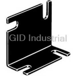
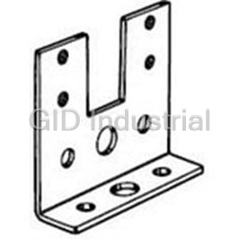
Long Angle Mounting Bracket, Slotted
E39L42
Part Number
E39L42
Price
Request Quote
Manufacturer
OMRON AUTOMATION
Lead Time
Request Quote
Category
Fasteners, Hardware and Fluid Transfer » Mounting Brackets
Specifications
Manufacturer
Omron Automation
Manufacturers Part #
E39L42
Industry Aliases
E39-L42
Sub-Category
Mounting Brackets
Factory Pack Quantity
1
Datasheet

Extracted Text
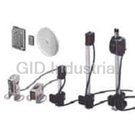
Compact Head Amplifier-separated Photoelectric Sensor E3C CSM_E3C_DS_E_11_2 Thin, Compact Head Saves Space and Mounts Closely. Built-in Interference Protection Provided. • Input indicator on the Sensor Unit simplifies settings. Be sure to read Safety Precautions on page 8. Ordering Information Sensors Sensor Units [Refer to Dimensions on page 9.] Red light Infrared light Sensing method Application Appearance Sensing distance Model E3C-S10 2M *1 10 Emitter E3C-S10L 2M 100 mm 12 11 Receiver E3C-S10D 2M 5.8 E3C-S50 2M *1 *2 13 Emitter E3C-S50L 2M 500 mm 7 Receiver E3C-S50D 2M 25 Small type E3C-1 2M *1 12 Emitter E3C-1L 2M 1 m 8 Receiver E3C-1D 2M 36 Through-beam E3C-2 2M *1 16 (Emitter + Receiver) Emitter E3C-2L 2M 2 m 18 12.4 Receiver E3C-2D 2M 12.5 E3C-S20W 2M 200 mm 15 2.8 Slim type 8 3 7.85 E3C-S30W 2M 3 300 mm 15 Side-view E3C-S30T 2M 15 26 Small type E3C-DS10 2M 100 mm 18 10 19.5 Diffuse-reflective Slim type E3C-DS5W 2M 50 mm 11 2.8 21 18 Side-view E3C-DS10T 2M 100 mm 8 36 Convergent-reflective Small type E3C-LS3R 2M 30±3 mm 10 *1. Through-beam Sensors are normally sold in sets that include both the Emitter and Receiver. *2. You cannot order the Emitter and Receiver with separate model numbers. Always order them together using the model number for the set (E3C-S50 2M). 1 E3C Amplifier Units [Refer to Amplifier Units on page 12.] Power supply Application Appearance Functions Model Self DC Slim type E3C-JC4P 2M 30 diagnostic 60 14 Accessories (Order Separately) Mounting Brackets [Refer to E39-L/E39-S/E39-R for Dimensions.] Appearance Model Quantity Remarks E39-L41 2 Provided with the E3C-1. Provided with the E3C-2. E39-L42 2 Can be used with the E3C-DS10. E39-L127-T1 1 E39-L127-T2 1 Can be used with the E3C-S10. E39-L127-T3 1 E39-L31 1* Can be used with the E3C-S50. Note: Refer to E39-L/E39-S/E39-R for Dimensions. * When using through-beam models, order one bracket for the Receiver and one for the Emitter. 2 E3C Ratings and Specifications Sensors Sensing method Through-beam E3C-S30T Model E3C-S10 E3C-S20W E3C-S50 E3C-1 E3C-2 Item E3C-S30W Sensing distance 100 mm 200 mm 500 mm 300 mm 1 m 2 m Standard sensing Opaque, 3-mm Opaque, 1.5-mm Opaque, 4-mm Opaque, 8-mm Opaque, 2-mm dia. min. object dia. min. dia. min. dia. min. dia. min. Emitter/Receiv- Emitter/Receiv- Directional angle Emitter/Receiver: 10 to 60° each Emitter/Receiver: 10 to 40° each er: 3 to 20° each er: 3 to 15° each Infrared LED Light source (wavelength) Infrared LED (950 nm) Infrared LED (950 nm) (940 nm) Ambient illuminance Incandescent lamp: 3,000 lx max., Sunlight 10,000 lx max. (Receiver side) Ambient temperature range Operating/Storage: −25 to 70°C (with no icing or condensation) Ambient humidity range Operating/Storage: 35% to 85%RH (with no condensation) Insulation resistance 20 MΩ min. at 500 VDC Dielectric strength 500 VAC at 50/60 Hz for 1 minute Vibration resistance Destruction: 10 to 55 Hz, 1.5-mm double amplitude for 2 hours each in X, Y, and Z directions 2 Shock resistance Destruction: 500 m/s for 3 times each in X, Y, and Z directions IEC 60529 IP64 IEC 60529 IP50 IEC 60529 IP64 IEC 60529 IP60 IEC 60529 IP66 Degree of protection Limited to indoor Limited to indoor Limited to indoor Limited to indoor Limited to indoor use use use use use Connection method Pre-wired models (standard length: 2 m) Weight (packed state) Approx. 50 g Approx. 24 g Approx. 60 g Approx. 120 g Case Polycarbonate ABS Polycarbonate Zinc die-cast Lens Polycarbonate Acrylics Polycarbonate Material Mounting --- Steel Brackets Phillips screw Phillips screw Mounting Mounting M2×8, spring M2×8, spring Bracket (with Bracket (with Instruction washer, flat Instruction washer, flat Accessories screws), screws), manual washer, M2 nut, manual washer, nut M2, instruction instruction instruction instruction manual manual manual manual Sensing method Diffuse-reflective Convergent-reflective Item Model E3C-DS5W E3C-DS10T E3C-DS10 E3C-LS3R 50 mm (White paper 100 × 100 mm (White paper 100 100 mm (White paper 50 × 30 ± 3 mm (White paper 10 Sensing distance 100 mm) × 100 mm) 50 mm) × 10 mm) Differential travel 20% max. of sensing distance 10% max. ±3% max. Light source (wavelength) Infrared LED (950 nm) Infrared LED (950 nm) Red LED (680 nm) Ambient illuminance Incandescent lamp: 3,000 lx max., Sunlight 10,000 lx max. (Receiver side) Ambient temperature range Operating/Storage: −25 to 70°C (with no icing or condensation) Ambient humidity range Operating/Storage: 35% to 85%RH (with no condensation) Insulation resistance 20 MΩ min. at 500 VDC Dielectric strength 500 VAC at 50/60 Hz for 1 minute Vibration resistance Destruction: 10 to 55 Hz, 1.5-mm double amplitude for 2 hours each in X, Y, and Z directions 2 Shock resistance Destruction: 500 m/s for 3 times each in X, Y, and Z directions Degree of protection IEC 60529 IP50 (Limited to indoor use) IEC 60529 IP64 (Limited to indoor use) Connection method Pre-wired models (standard length: 2 m) Weight (packed state) Approx. 50 g Approx. 55 g Case Polycarbonate Material Lens Polycarbonate Phillips screw M2×8, Accessories spring washer, flat washer, Instruction manual M2 nut, instruction manual 3 E3C Amplifier Units Item Model E3C-JC4P Power supply 12 to 24 VDC±10%, ripple (p-p): 1 V max. voltage Power (current) 40 mA max. consumption Load power supply voltage: 24 VDC max., load current: 100 mA max., NPN open collector output type (residual voltage: Control output 1 V max.) Light-ON/Dark-ON switch selectable Timer function OFF-delay 0/40 ms (switch selectable) Ambient temperature range Operating: −10° to 55°C, Storage: −25° to 70°C (with no icing or condensation) Ambient humidity range Operating: 35% to 85%, Storage: 35% to 85% (with no condensation) Insulation resistance 20 MΩ min. at 500 VDC Dielectric strength 1,000 VAC at 50/60 Hz for 1 minute Vibration resistance Destruction: 10 to 55 Hz, 1.5-mm double amplitude for 2 hours each in X, Y, and Z directions 2 Shock resistance Destruction: 300 ms three times in each of X, Y and Z directions Degree of protection IEC IP40 (limited to indoor use) Protection Reverse polarity protection, output short-circuit protection, mutual interference prevention Response time Operate or reset: 1 ms max. Connection method Terminal block input cable pullout (standard cable length: 2 m) Weight Approx. 80 g (packed state) Case ABS Material Mounting Brackets Iron Accessories Mounting Bracket, Adjustment screwdriver, Caution label, Instruction manual 4 E3C Engineering Data (Reference Value) Parallel Operating Range Through-beam Through-beam Through-beam E3C-S10 E3C-S20W E3C-S50 200 200 200 Y Y 150 Y 150 150 X X X 100 100 100 50 50 50 0 0 0 50 100 150 200 250 300 0.2 0.4 0.6 0.8 1 50 100 150 200 250 300 Sensing Sensing Sensing −50 distance X (mm) −50 −50 distance X (mm) distance X (mm) −100 −100 −100 −150 −150 −150 −200 −200 −200 Through-beam Through-beam Through-beam E3C-1 E3C-2 E3C-S30T/-S30W 200 200 200 Y Y 150 150 150 X X 100 100 100 Y 50 50 50 X 0 0 0 600 1 2 3 4 200 400 800 0.5 1 1.5 2 Sensing Sensing Sensing distance X (mm) −50 −50 −50 distance distance X (mm) X (mm) −100 −100 −100 −150 −150 −150 −200 −200 −200 Operating Range Diffuse-reflective Diffuse-reflective Diffuse-reflective E3C-DS5W E3C-DS10T E3C-DS10 (Example 1) 40 40 40 X ON Moving direction X Y OFF of object 30 30 Y 30 Moving Y direction X of object Optical 20 20 20 axis 10 10 10 0 0 0 20 40 60 80 100 120 160 20 40 60 80 100 120 40 80 120 200 140 Sensing 160 Sensing −10 distance −10 −10 distance Sensing X (mm) X (mm) distance X (mm) −20 −20 −20 −30 −30 −30 −40 −40 −40 5 Operating position Y (mm) Operating position Y (mm) Operating position Y (mm) Operating position Y (mm) Operating position Y (mm) Operating position Y (mm) Operating position Y (mm) Operating position Y (mm) Operating position Y (mm) E3C Diffuse-reflective Convergent-reflective Convergent-reflective E3C-DS10 (Example 2) E3C-LS3R (Example 1) E3C-LS3R (Example 2) 40 2 2 X X ON Moving direction ON X ON Moving direction of object OFF OFF of object OFF 30 Y Y Y Moving Optical Optical Optical direction 20 1 1 axis axis axis of object 10 0 0 0 40 80 120 200 22 26 28 30 32 34 36 38 22 26 28 30 32 34 36 38 Sensing distance 160 Sensing distance X (mm) 24 X (mm) −10 24 Sensing distance −20 −1 −1 X (mm) −30 −40 −2 −2 Excess Gain vs. Set Distance E3C-S20W E3C-S30T/-S30W E3C-S50 100 100 100 70 70 70 50 50 50 30 30 30 10 10 10 7 7 7 5 5 5 3 3 3 Operating Level Operating Level Operating Level 1 1 1 0.7 0.7 0.7 0.5 0.5 0.5 0.3 0.3 0.3 0.1 0.1 0.1 0 100 200 300 400 500 0 0.2 0.4 0.6 0.8 1 0 0.2 0.4 0.6 0.8 1 Set distance (mm) Set distance (mm) Set distance (mm) E3C-DS5W E3C-DS10T E3C-LS3R 100 100 100 70 70 70 50 50 50 30 30 30 10 10 10 7 7 7 5 5 5 3 3 3 Operating Level Operating Level Operating Level 1 1 1 0.7 0.7 0.7 0.5 0.5 0.5 0.3 0.3 0.3 0.1 0.1 0.1 0 50 100 150 200 0 50 100 150 200 0 10 203040 50 Set distance (mm) Set distance (mm) Set distance (mm) 6 Operating position Y (mm) Operating position Y (mm) Operating position Y (mm) Excess Gain ratio Excess Gain ratio Excess Gain ratio Excess Gain ratio Excess Gain ratio Excess Gain ratio E3C I/O Circuit Diagrams NPN output Operation Operation Model Timing charts Output circuit mode selector Incident light No incident light Light Brown12 to 24 VDC ON indicator L-ON OFF Light Stability Light-ON (red) 100 mA max. ON (LIGHT ON) indicator indicator Output Load transistor OFF (red) (green) Black 40 ms Z0 ON Load Photo- Output (relay etc.) OFF electric E3C-JC4P Sensor Incident light Blue 0 V Main No incident light Circuit Light Z1 ON indicator D-ON OFF (red) Dark-ON Orange ON Output (DARK ON) Self diagnostic output transistor OFF 40 ms 50 mA max. Load ON (relay etc.) OFF Connection Amplifier Units Connected to the through-beam model Connected to the reflective model Note Emitter Receiver Emitter/receiver Note: 1. The strip-off length of the shielded cable should Shield White Shield White always be 20 mm max. on E3C-JC4P the Receiver side (white) Red Shield Red Shield and 50 mm max. on the Emitter side (red). Nomenclature/Settings Amplifier Units Nomenclature Stability indicator Light indicator E3C-JC4P (green) (red) Sensitivity adjuster (4-turn endless asjuster) Operation selector 7 E3C Safety Precautions Refer to Warranty and Limitations of Liability. WARNING This product is not designed or rated for ensuring safety of persons either directly or indirectly. Do not use it for such purposes. Precautions for Correct Use Do not use the product in atmospheres or environments that exceed product ratings. Amplifier Units ● Wiring Extension Cable Connection of Amplifier Unit and Sensor Through-beam Always run the shielded wires of the Emitter and Receiver separately. Cable Replacement Specified cable Also, route the sensor cable along the cable grooves of the cover and cable Model sensor and fix it with the cover. 1-conductor shield/ Polyethylene insulation shield vinyl wire, conduc- Round cable White (Shield) tor cross section: 2 0.3 mm min. Receiver Shield E3C-S10 E3C-1 Shield White (polyethylene) Emitter E3C-2 2.4 dia. White (Shield) Red E3C-S50 (vinyl) 12-conductor, 0.18 dia. Gray (vinyl sheath) Vinyl insulation shield round cable Sheath Shield E3C-S20W 1.7 dia. Polyethylene Sensor Units Conductor 1-conductor shield/ 12-conductor, 0.18 dia. vinyl wire, conduc- ● Wiring Vinyl insulation shield round cable tor cross section: 2 Extension Cable (robot cable) 0.3 mm min. • The extension distance of the sensor connection cable should be Sheath E3C-S30T Shield within 10 m including sensor cable. E3C-S30W 1.8 dia. • The strip-off length of the core in the connection cable should be 20 Polyethylene mm max. on the Receiver side and 50 mm max. on the Emitter side, Conductor 30-conductor, 0.08 dia. and the core should be as short as possible. Avoid using the joint terminal and connector. Reflective model Cable Replacement Specified cable cable Model Socket Vinyl insulation shielded parallel ca- ble When there is no1- E3C-DS10 Sheath 20 mm max. conductor shielded, E3C-DS10T Internal vinyl cable (parallel sheath • Use independent shielded wires for the Emitter and Receiver. E3C-VS1G wire), use two 1- 2.4 Shield E3C-VS3R Using a common shielded wire can cause a malfunction. conductor shielded, E3C-LS3R Polyethylene vinyl wires. Conductor 4.3 12-conductor, 0.18 dia. Vinyl insulation shielded parallel ca- ble When there is no1- conductor shielded, Sheath E3C-DS5W vinyl cable (parallel Shield E3C-VS7R wire), use two 1- E3C-VM35R Polyethylene conductor shielded, Conductor vinyl wires. 7-conductor, 0.18 dia. ● Others When the E3C is used in a place where high-frequency noise will be generated, e.g. ultrasonic welder, grounding the 0-V terminal (on the shield side of the connection cable) of the Receiver may avoid a malfunction caused by induction. 8 E3C (Unit: mm) Dimensions Tolerance class IT16 applies to dimensions in this data sheet unless otherwise specified. Sensors Sensor Units E3C-S10 10 5.8 Light indicator (red) Two, 2.9 dia. 2.3 (emitter only) 12 7.5 2.8 2 Emitter/ receiver surface 2.8 5.2 dia. 2.4-dia. shielded cable with 1 conductor 2 (Conductor cross section: 0.3 mm ), Emitter: E3C-S10L Standard length: 2 m Receiver: E3C-S10D E3C-S50 Light indicator (red) Emitter/receiver label 11 (emitter only) ±0.2 7 2.9 3.5 13 8±0.2 5.7 dia. Emitter/receiver surface Two, 3.2 dia. 2.4-dia. shielded cable with 1 conductor 2 (Conductor cross section: 0.3 mm ), Standard length: 2 m Emitter: E3C-S50L Receiver: E3C-S50D E3C-1 25 13 3 10 2 8 6.4 6 dia. 3.2 8 12 5.5 5 3.2 13.5 Light indicator (red) 4 Iron (emitter only) 12 M3 2.4-dia. shielded cable with 1 conductor 2 (Conductor cross section: 0.3 mm ), Standard length: 2 m Emitter/receiver surface 6 5 12 16.5 12.5 3.5 Optical axis position Emitter: E3C-1L Lens 4 dia. Receiver: E3C-1D (A)* * Mounting Bracket can be attached to side A. 2 E3C-2 36 12.4 9.4 8 dia. 3.2 8 12 5.5 3.2 4.5 M3 23 Light indicator (red) Iron 2.4-dia. shielded cable with 1 conductor (emitter only) 2 (conductor cross section: 0.3 mm ), Standard length: 2 m Emitter/receiver surface 7 16 21 17 6.7 Optical 3.3 axis position Lens 8 dia. (A)* 13.3 20 Emitter: E3C-2L * Mounting Bracket can be attached to side A. Receiver: E3C-2D 9 E3C E3C-S20W Receiver Emitter 2 2 dia. (receiver) 2,000 18 3.6 4.5 4.5 Light indicator (red) (white) (Red) 4 5 12.5 (6) 1.75-dia. shielded cable 2.5 with 1 conductor 2 dia. (emitter) ±0.2 11 (Conductor cross section: 2 3.5 0.3 mm ), Standard length: 2 m 3.8 dia. Emitter: E3C-S20LW 2.3 dia. 1.4 2.8 Receiver: E3C-S20DW E3C-S30W Emitter Receiver 1.5 dia. (receiver) Light indicator 5 15 (red) 1.2 dia. 2.4 5 1.5 dia. (emitter) 2 4 8 2.2 1.93-dia. shielded robotics cable with 1 conductor 7.5 (Conductor cross section: 2.2 3.6 dia. 2 12 0.15 mm ), dia. Standard length: 2 m 1.5 3 Emitter: E3C-S30LW Receiver: E3C-S30DW E3C-S30T Receiver Emitter 5 5 1.5 dia. (receiver) 2.4 1.5 dia. (emitter) Light indicator 15 (red) 1.2 dia. 3.85 7.85 2.2 1.93-dia. shielded robotics 7.5 cable with 1 conductor 2.2 3.6 dia. (Conductor cross section: 12 2 dia. 0.15 mm ), Standard length: 2 m 1.5 3 Emitter: E3C-S30LT Receiver: E3C-S30DT E3C-DS10 2 26 4.3 9 10 Emitter Receiver Lens 19 3.9 5 3.2 R1.2 4 3.2 10 15 5 6.6 2.4 2.4-dia. shielded cable R3.3 Light indicator with 2 conductors 8.5±1 Optical axis 2 (red) (Conductor cross section: 0.3 mm ), position Standard length: 2 m 10 E3C E3C-DS5W 2 2,000 18 Receiver 4.5 4 4 ±0.2 7 7 19.5 6 3.8 dia. 1.8 × 3.6-dia. shielded 2.3 dia. 2.5 40 cable with 2 conductors (Conductor cross ±0.2 11 1.4 2 section: 0.18 mm ), Emitter 3.5 Standard length: 2 m 2.8 E3C-DS10T 1.5 21 2,000 4.6 11 40 2.5 16±0.2 Two, 3.2-dia. mounting holes 2.5 Emitter Receiver 8 6 2.4-dia. shielded cable with 2 conductors 7 2 7±0.2 (Conductor cross section: 0.3 mm ), Standard length: 2 m E3C-LS3R 2 36 4.3 9 10 Emitter Receiver Lens 3.2 R1.2 5.3 13 18 6.5 6.6 2.4 Optical axis ±1 313 R3.3 position 30 Light indicator 2.4-dia. shielded cable with 2 conductors 2 (red) (Conductor cross section: 0.3 mm ), Standard length: 2 m 11 E3C Amplifier Units With Mounting Bracket Attached E3C-JC4P Light indicator Timer mode selector switch M2.6 Stability indicator Operation selector Sensitivity adjuster Caution label* (10) 50 4.5-dia. vinyl-insulated round cable with 5 4 conductors (Conductor cross section: 2 0.2mm , Insulator diameter: 1.2mm), Standard length: 2 m 3.5 30 12 6 14 10 43 2.5 60 Two, 3.3 dia. Mounting bracket (iron) (detachable) 23.5 16 R1.6 3.2 2 14 35.5 *After adjusting the sensitivity, attach the caution label at the location indicated by above to prevent malfunction. Accessories (Order Separately) Mounting Brackets Refer to E39-L/E39-S/E39-R for details. 12 Terms and Conditions Agreement Read and understand this catalog. Please read and understand this catalog before purchasing the products. Please consult your OMRON representative if you have any questions or comments. Warranties. (a) Exclusive Warranty. Omron’s exclusive warranty is that the Products will be free from defects in materials and workmanship for a period of twelve months from the date of sale by Omron (or such other period expressed in writing by Omron). Omron disclaims all other warranties, express or implied. (b) Limitations. OMRON MAKES NO WARRANTY OR REPRESENTATION, EXPRESS OR IMPLIED, ABOUT NON-INFRINGEMENT, MERCHANTABILITY OR FITNESS FOR A PARTICULAR PURPOSE OF THE PRODUCTS. BUYER ACKNOWLEDGES THAT IT ALONE HAS DETERMINED THAT THE PRODUCTS WILL SUITABLY MEET THE REQUIREMENTS OF THEIR INTENDED USE. Omron further disclaims all warranties and responsibility of any type for claims or expenses based on infringement by the Products or otherwise of any intellectual property right. (c) Buyer Remedy. Omron’s sole obligation hereunder shall be, at Omron’s election, to (i) replace (in the form originally shipped with Buyer responsible for labor charges for removal or replacement thereof) the non-complying Product, (ii) repair the non-complying Product, or (iii) repay or credit Buyer an amount equal to the purchase price of the non-complying Product; provided that in no event shall Omron be responsible for warranty, repair, indemnity or any other claims or expenses regarding the Products unless Omron’s analysis confirms that the Products were properly handled, stored, installed and maintained and not subject to contamination, abuse, misuse or inappropriate modification. Return of any Products by Buyer must be approved in writing by Omron before shipment. Omron Companies shall not be liable for the suitability or unsuitability or the results from the use of Products in combination with any electrical or electronic components, circuits, system assemblies or any other materials or substances or environments. Any advice, recommendations or information given orally or in writing, are not to be construed as an amendment or addition to the above warranty. See http://www.omron.com/global/ or contact your Omron representative for published information. Limitation on Liability; Etc. OMRON COMPANIES SHALL NOT BE LIABLE FOR SPECIAL, INDIRECT, INCIDENTAL, OR CONSEQUENTIAL DAMAGES, LOSS OF PROFITS OR PRODUCTION OR COMMERCIAL LOSS IN ANY WAY CONNECTED WITH THE PRODUCTS, WHETHER SUCH CLAIM IS BASED IN CONTRACT, WARRANTY, NEGLIGENCE OR STRICT LIABILITY. Further, in no event shall liability of Omron Companies exceed the individual price of the Product on which liability is asserted. Suitability of Use. Omron Companies shall not be responsible for conformity with any standards, codes or regulations which apply to the combination of the Product in the Buyer’s application or use of the Product. At Buyer’s request, Omron will provide applicable third party certification documents identifying ratings and limitations of use which apply to the Product. This information by itself is not sufficient for a complete determination of the suitability of the Product in combination with the end product, machine, system, or other application or use. Buyer shall be solely responsible for determining appropriateness of the particular Product with respect to Buyer’s application, product or system. Buyer shall take application responsibility in all cases. NEVER USE THE PRODUCT FOR AN APPLICATION INVOLVING SERIOUS RISK TO LIFE OR PROPERTY OR IN LARGE QUANTITIES WITHOUT ENSURING THAT THE SYSTEM AS A WHOLE HAS BEEN DESIGNED TO ADDRESS THE RISKS, AND THAT THE OMRON PRODUCT(S) IS PROPERLY RATED AND INSTALLED FOR THE INTENDED USE WITHIN THE OVERALL EQUIPMENT OR SYSTEM. Programmable Products. Omron Companies shall not be responsible for the user’s programming of a programmable Product, or any consequence thereof. Performance Data. Data presented in Omron Company websites, catalogs and other materials is provided as a guide for the user in determining suitability and does not constitute a warranty. It may represent the result of Omron’s test conditions, and the user must correlate it to actual application requirements. Actual performance is subject to the Omron’s Warranty and Limitations of Liability. Change in Specifications. Product specifications and accessories may be changed at any time based on improvements and other reasons. It is our practice to change part numbers when published ratings or features are changed, or when significant construction changes are made. However, some specifications of the Product may be changed without any notice. When in doubt, special part numbers may be assigned to fix or establish key specifications for your application. Please consult with your Omron’s representative at any time to confirm actual specifications of purchased Product. Errors and Omissions. Information presented by Omron Companies has been checked and is believed to be accurate; however, no responsibility is assumed for clerical, typographical or proofreading errors or omissions. 2015.9 In the interest of product improvement, specifications are subject to change without notice. OMRON Corporation Industrial Automation Company http://www.ia.omron.com/ (c)Copyright OMRON Corporation 2015 All Right Reserved.
Frequently asked questions
How does Electronics Finder differ from its competitors?

Is there a warranty for the E39L42?
Which carrier will Electronics Finder use to ship my parts?
Can I buy parts from Electronics Finder if I am outside the USA?
Which payment methods does Electronics Finder accept?
Why buy from GID?

Quality
We are industry veterans who take pride in our work

Protection
Avoid the dangers of risky trading in the gray market

Access
Our network of suppliers is ready and at your disposal

Savings
Maintain legacy systems to prevent costly downtime

Speed
Time is of the essence, and we are respectful of yours
Related Products
Super-Compact Proximity Sensor E2S-W23-U1
Short Angle Slotted Bracket with Stainless Steel Material E39-L103
Long Angle Slotted Mounting Bracket for Compact Photoelectric Sensor E39-L104
Flat Stainless Steel Mounting Bracket, Slotted E39-L120
Long Angle Mounting Bracket for using with E3C-S10 Photoelectric Sensor E39L127T1
Long Angle Mounting Bracket for using with E3C-S10 Photoelectric Sensor E39L127T2
Request a Quote

The quote request has been received
Close

Facing challenges or have inquiries? Feel free to contact us!
Call Us +1-469-283-2440
What they say about us
FANTASTIC RESOURCE
One of our top priorities is maintaining our business with precision, and we are constantly looking for affiliates that can help us achieve our goal. With the aid of GID Industrial, our obsolete product management has never been more efficient. They have been a great resource to our company, and have quickly become a go-to supplier on our list!
Bucher Emhart Glass
EXCELLENT SERVICE
With our strict fundamentals and high expectations, we were surprised when we came across GID Industrial and their competitive pricing. When we approached them with our issue, they were incredibly confident in being able to provide us with a seamless solution at the best price for us. GID Industrial quickly understood our needs and provided us with excellent service, as well as fully tested product to ensure what we received would be the right fit for our company.
Fuji
HARD TO FIND A BETTER PROVIDER
Our company provides services to aid in the manufacture of technological products, such as semiconductors and flat panel displays, and often searching for distributors of obsolete product we require can waste time and money. Finding GID Industrial proved to be a great asset to our company, with cost effective solutions and superior knowledge on all of their materials, it’d be hard to find a better provider of obsolete or hard to find products.
Applied Materials
CONSISTENTLY DELIVERS QUALITY SOLUTIONS
Over the years, the equipment used in our company becomes discontinued, but they’re still of great use to us and our customers. Once these products are no longer available through the manufacturer, finding a reliable, quick supplier is a necessity, and luckily for us, GID Industrial has provided the most trustworthy, quality solutions to our obsolete component needs.
Nidec Vamco
TERRIFIC RESOURCE
This company has been a terrific help to us (I work for Trican Well Service) in sourcing the Micron Ram Memory we needed for our Siemens computers. Great service! And great pricing! I know when the product is shipping and when it will arrive, all the way through the ordering process.
Trican Well Service
GO TO SOURCE
When I can't find an obsolete part, I first call GID and they'll come up with my parts every time. Great customer service and follow up as well. Scott emails me from time to time to touch base and see if we're having trouble finding something.....which is often with our 25 yr old equipment.
ConAgra Foods