

 Manufacturers
OMRON AUTOMATION E3F2R2RC4M10M

Description
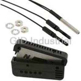
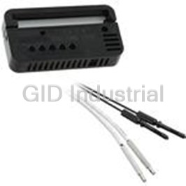
Photoelectric Sensor Polarized Retro-Reflective Light ON/Dark ON NPN 2m
E3F2R2RC4M10M
Part Number
E3F2R2RC4M10M
Price
Request Quote
Manufacturer
OMRON AUTOMATION
Lead Time
Request Quote
Category
Sensors and Transducers » Photoelectric Sensor
Specifications
Manufacturer
Omron Automation
Manufacturers Part #
E3F2R2RC4M10M
Industry Aliases
E3F2-R2RC4-M 10M
Sub-Category
Photoelectric Sensors
Factory Pack Quantity
1
Datasheet

Extracted Text
Cylindrical photoelectric sensors in M18 plastic or brass housings E3F2 • Complete sensor portfolio in plastic and metal housing IP67, IP69K for highest water resis- tance High immunity against electro-mag- netic noise and ambient light Special beam models High power LED to compensate for dirt and misalignment Performance and portfolio variety *1 *2 Sensing method Shape Plastic Metal 90° Optics AC power supply Through-beam 7 m 7 m - 3 m Retro-reflective 4 m 4 m 2 m 1 m Diffuse-reflective 1 m 1 m 0.3 m 0.3 m Diffuse-reflective 0.1 m 0.1 m (background suppression) *1 SUS types see seperate datasheet *2 AC-types see seperate datasheet L-on / D-on selectable by wiring M12 connector or pre-wired. E3F2 1 Selection Guide Housing Material: Plastic Sensing method Sensing Connection method Order code distance PNP output NPN output *1 Through-beam 7 m E3F2-7B4 2M E3F2-7C4 2M –– 2 m – – –– E3F2-7B4-P1 E3F2-7C4-P1 *2 Retro-reflective with M.S.R. 0.1 to 4 m E3F2-R4B4-E 2M E3F2-R4C4-E 2M –– 2 m – *3 (adjustable) E3F2-R4B4-P1-E E3F2-R4C4-P1-E – –– *2 *4 Retro-reflective with M.S.R. 0.1 to 2 m E3F2-R2RB41-E 2M E3F2-R2RC41-E 2M –– 2 m – E3F2-R2RB41-P1-E E3F2-R2RC41-P1-E – –– Diffuse-reflective 0.1 m (fixed, E3F2-DS10B4-N 2M E3F2-DS10C4-N 2M –– 2 m – wide-beam) E3F2-DS10B4-P1 E3F2-DS10C4-P1 – –– 0.3 m –– 2 m – E3F2-DS30B4 2M E3F2-DS30C4 2M (adjustable) – –– E3F2-DS30B4-P1 E3F2-DS30C4-P1 1m –– 2 m – E3F2-D1B4 2M E3F2-D1C4 2M (adjustable) – –– E3F2-D1B4-P1 E3F2-D1C4-P1 Diffuse-reflective 0.3 m E3F2-DS30B41 2M E3F2-DS30C41 2M –– 2 m – (adjustable) E3F2-DS30B41-P1 E3F2-DS30C41-P1 – –– Diffuse reflective 0.1 m (fixed) E3F2-LS10B4 2M E3F2-LS10C4 2M –– 2 m – (background suppression) E3F2-LS10B4-P1 E3F2-LS10C4-P1 – –– *1. Pre-wired connectors are available on request. Please contact your OMRON representative. *2. Order reflector seperately. Models with reflector included are also available. Please contact your OMRON representative. *3. Measured with reflector E39-R1S *4. Measured with reflector E39-R1 Note: Standard cable length is 2 m. Models provided with a 5 m long cable are available. When ordering, specify the cable length by adapting the length of the cable (e.g. E3F2-R4B4-E 5M). For other cable length please contact your OMRON sales representative. Housing material: Metal (Nickel plated brass) Sensing method Sensing Connection method Order code distance PNP output NPN output *1 Through-beam 7 m E3F2-7B4-M 2M E3F2-7C4-M 2M –– 2 m – E3F2-7B4-M1-M E3F2-7C4-M1-M – –– *2 Retro-reflective with M.S.R. 0.1 to 4 m E3F2-R4B4-M-E 2M E3F2-R4C4-M-E 2M –– 2 m – *3 (adjustable) E3F2-R4B4-M1-M-E E3F2-R4C4-M1-M-E – –– *2 *4 Retro-reflective with M.S.R. 0.1 to 2 m E3F2-R2RB41-M-E 2M E3F2-R2RC41-M-E 2M –– 2 m – E3F2-R2RB41-M1-M-E E3F2-R2RC41-M1-M-E – –– Diffuse-reflective 0.1 m (fixed, –– 2 m – E3F2-DS10B4-M 2M E3F2-DS10C4-M 2M wide-beam) – –– E3F2-DS10B4-M1-M E3F2-DS10C4-M1-M 0.3 m –– 2 m – E3F2-DS30B4-M 2M E3F2-DS30C4-M 2M (adjustable) – –– E3F2-DS30B4-M1-M E3F2-DS30C4-M1-M 1m E3F2-D1B4-M 2M E3F2-D1C4-M 2M –– 2 m – (adjustable) E3F2-D1B4-M1-M E3F2-D1C4-M1-M – –– Diffuse-reflective 0.3 m E3F2-DS30B41-M 2M E3F2-DS30C41-M 2M –– 2 m – (adjustable) E3F2-DS30B41-M1-M E3F2-DS30C41-M1-M – –– 2 Standard Photoelectric Sensors Sensing method Sensing Connection method Order code distance PNP output NPN output *1 Diffuse-reflective 0.1 m (fixed) E3F2-LS10B4-M 2M E3F2-LS10C4-M 2M –– 2 m – (background suppression) E3F2-LS10B4-M1-M E3F2-LS10C4-M1-M – –– *1. Pre-wired connectors are available on request. Please contact your OMRON representative. *2. Order reflector separately. Models with reflector E39-R1S included are available. Please contact your OMRON representative. *3. with reflector E39-R1S *4. with reflector E39-R1 Note: Standard cable length is 2 m. Models provided with a 5 m long cable are available. When ordering, specify the cable length by adapting the length of the cable (e.g. E3F2-R4B4-E 5M). For other cable length please contact your OMRON sales representative. Accessories (Order Separately) *1 Name Sensing distance (typical) Remark Order code Reflectors 3 m [100 mm] (axial types) 60 x 40 mm E39-R1 2 m [100 mm] (radial types) 4 m [100 mm] (axial types) 60 x 40 mm E39-R1S 2 m [100 mm] (radial types) 5 m [100 mm] (axial types) E39-R7 ∅ 84 mm 2.5 m [100 mm] (radial types) 6 m [100 mm] (axial types) 100 x 100 mm E39-R8 3 m [100 mm] (radial types) 5 m [100 mm] (axial types) 80 x 80 mm E39-R40 2.5 m [100 mm] (radial types) Tape Reflectors 0.7 m [150 mm] (axial types) 35 x 10 mm E39-RS1 1.1 m [150 mm] (axial types) 35 x 40 mm E39-RS2 1.4 m [150 mm] (axial types) 80 x 70 mm E39-RS3 Lens Cap E39-F31 Mounting Bracket screw mount Y92E-B18 *1. Values in parentheses indicate the minimum required distance between the sensor and reflector. For detailed information about Accessories, refer to the main chapter “Accessories” at the end of the document. Sensor I/O Connectors Cord Shape Cable type Order code Standard Straight 2 m Four-wire type XS2F-D421-D80-A 5 m XS2F-D421-G80-A L-shaped 2 m XS2F-D422-D80-A 5 m XS2F-D422-G80-A Vibration-proof Straight 2 m XS2F-D421-D80-R robot cable 5 m XS2F-D421-G80-R L-shaped 2 m XS2F-D422-D80-R 5 m XS2F-D422-G80-R E3F2 3 Specifications Ratings Item E3F2-7@ E3F2-R4@-@ E3F2-DS10@ E3F2-DS30@ E3F2-D1@4-@ E3F2-LS10@4-@ Sensing method Through-beam Retro-reflective Diffuse-reflective with M.S.R. Wide beam Potentiometer adjustment Background suppression Power supply voltage 10 to 30 VDC Current consumption 50 mA max. 30 mA max. 25 mA max. 30 mA max. Sensing distance 7 m 0.1 to 4 m 0.1 m 0.3 m 1 m 0.1 m (with E39-R1S) (5 x 5 cm white (10 x 10 cm white (30 x 30 cm white (10 x 10 cm white mat paper) mat paper) mat paper) mat paper) Standard object Opaque: Opaque: – 11 mm dia. min. 56 mm dia. min. Directional angle 3° to 20° – Differential travel – 20% max. 5% max (hysteresis) Black/white error – 3% Response time Operation and 1 ms max 2.5 ms max. 1 ms max. Reset: 2.5 ms max. Control output Transistor (open collector), load current: 100 mA max. (residual voltage: 2 V max.) Power reset time 50 ms 100 ms max. 50 ms 100 ms Ambient illumination Incandescent lamp:3000 lx max. / Sunlight:10000 lx max. Ambient temperature Operating: -25 to 55 °C / Storage: -30 to 70 °C (with no icing or condensation) Ambient humidity Operating: 35% to 85% / Storage: 35% to 95% (with no condensation) Insulation resistance 20 MΩ min. at 500 V DC between energized parts and case Dielectric strength 1000 VAC max., 50 / 60 Hz for 1 min between energized parts and case Vibration resistance 10 to 55 Hz, 1.5 mm double amplitude for 2 hrs each direction (X, Y, Z) 2 Shock resistance Destruction: 500 m/s each direction (X, Y, Z) *1 Degree of protection IEC 60529 IP67, IP69K after DIN 40050-9 Light source (wave Infrared LED Red LED Infrared LED (880 nm) Red LED length) (950 nm) (660 nm) (660 nm) Indicators Light incident / Light incident Light incident / power indicator for Light incident Output indicator power indicator (red) / light source (red) (red) / (orange) / for light source stability (green) stability (green) stability (green) (red) Sensitivity adjustment Fixed Adjustable Fixed Adjustable Fixed *2 Connection method 2 m, 5 m pre-wired cable (PVC, dia. 4 mm (18 / 0.12) ) or M12-connector Operation mode Light-ON or Dark-ON selectable by wiring Weight (approx.) Plastic pre-wired 120 g 60 g case (2 m) connector 40 g 20 g Metal pre-wired 180 g 90 g case (2 m) connector 120 g 50 g Circuit protection Output short-circuit and power supply reverse polarity *3 Housing materials Case: ABS (plastic models) or nickel brass (metal models); lens: PMMA *1. The IP69k test according to DIN 40 050 part 9 is intended to simulate high pressure/steam cleaning. During the test 14-16 l/min water at 80°C is sprayed onto the sensor from different angles with 8000-10000 kPa. The sensor may not suffer any damaging effects from high pressure water in appearance and functionality. *2. For other cable materials (e.g. PUR) contact your OMRON sales representative. *3. For stainless steel types refer to separate datasheet E3F2 SUS 4 Standard Photoelectric Sensors Engineering Data (Typical) Operating Range (typical) Through-beam Models (axial) Retro-reflective Models (axial) Retro-reflective Models (radial) E3F2-7@4-@ E3F2-R4@4@-@ (polarizing) E3F2-R2R@41-@ (polarizing) and reflectors 250 100 Typical sensing distance typical sensing distances: E39-RS3 E39-R1: 2.4 m 200 E39-R1S E39-R7: 2.7 m E39-R40 E39-R8: 3.1 m E39-R7 150 E39-R8 50 100 50 0 0 -50 - 100 –50 - 150 Reflector Reflector Y - 200 Y X X –100 - 250 0 0.5 1 1.5 2 2.5 3 3.5 4 01 2 3 45 6 7 8 9 Distance X (m) Distance X (m) Diffuse-reflective Models (axial) Diffuse-reflective Models (axial) Diffuse-reflective Models (radial) E3F2-DS10@4-@ (wide-beam type) E3F2-DS30@4-@ E3F2-DS30@41-@ 15 40 40 Sensitivity adjusted to maximum Sensitivity adjusted to 390 mm Sensitivity adjusted to 400 mm 30 30 White paper (90% reflectivity) 10 20 20 5 10 10 white paper 0 white paper 0 Sensing object: 0 (50 x 50 mm) (100 x 100 mm) 100 x 100 mm –10 –10 –5 –20 Sensing distance adjustable –20 between 0 and 550 mm –10 Object –30 Object –30 Object Y Y Y X X X –15 –40 –40 0 20 40 60 80 100 120 140 0 100 200 300 400 500 600 0 100 200 300 400 500 Distance X (mm) Distance X (mm) Distance X (mm) Diffuse-reflective Models (axial) E3F2-D1@4-@ 100 80 60 40 20 Sensing object: 0 300 x 300 mm -20 -40 -60 Object -80 Y X -100 0 200 400 600 800 1000 1200 1400 1600 Distance X (mm) E3F2 5 Distance Y (mm) Distance Y (mm) Distance Y (mm) Distance Y (mm) Distance Y (mm) Distance Y (mm) Excess Gain Ratio vs. Distance (typical) Through-beam Models (axial) Retro-reflective Models (axial) Retro-reflective Models (radial) E3F2-7@4-@ E3F2-R4@4@-@ E3F2-R2R@41-@ (polarizing) and reflectors 100 100 100 Reflectors: E39-RS3 E39-R1S E39-R40 E39-R7 E39-R8 10 10 10 reflector E39-R1 1 1 1 reflector E39-R7 reflector E39-R8 0.1 0.1 0.1 0 2 4 6 8 10 12 0 12 3 45 02 4 6 8 10 Distance X (m) Distance X (m) Distance X (m) Diffuse-reflective Models (axial) Diffuse-eflective Models (axial) Diffuse-reflective Models (radial) E3F2-DS10@4-@ (wide-beam type) E3F2-DS30@4-@ E3F2-DS30@41-@ 100 100 100 Sensitivity adjusted to maximum Sensing object: Sensing object: 100 x 100 mm Sensing object: 100 x 100 mm 50 x 50 mm Sensitivity adjusted to 390 mm 10 10 10 White paper (90% reflectivity) White paper (90% reflectivity) White paper (90% reflectivity) Grey paper 1 1 1 (18% reflectivity) Grey paper Grey paper (18% reflectivity) (18% reflectivity) 0.1 0.1 0.1 0 200 400 600 800 1000 0 20 40 60 80 100 120 140 0 100 200 300 400 500 Distance X (mm) Distance X (mm) Distance X (mm) Diffuse-reflective Models (axial) E3F2-D1@4-@ 100 10 1 0,1 0 0.5 1 1.5 2 Distance(m) 6 Standard Photoelectric Sensors Excess gain Excess gain Excess gain Excess gain Excess Gain Excess gain Excess gain Light spot vs sensing distance Incline (horizontal) Incline (vertical) Background suppression Models Background suppression Models Background suppression Models E3F2-LS@ E3F2-LS@ E3F2-LS@ 6 20,00% 20,00% 10,00% 10,00% 4 0,00% 0,00% 2 -10,00% -10,00% 0 -20,00% -20,00% 050 100 150 -40 -30 -20 -10 0 10 20 3040 -40 -30 -20 -10 0 10 20 3040 Distance(mm) Incline Angle (˚) Incline Angle (˚) Object material vs sensing distance Background suppression Models E3F2-LS@ 120 100 80 60 40 20 0 White Veneer Card- Black Black SUS Mirror rubber paper board paper surface Material E3F2 7 Sensing distance (mm) Spot diameter(mm) Sensing Distence movement (%) Sensing Distence movement (%) Operation Structure of Sensor I/O Connector Output Circuits Classification Wire color Connector Use pin No. 1 Brown 2 White DC Brown ➀ Power supply (+V) 3 Blue Black 4 ➁ White Mode selection Lon/Don ➂ Blue Power supply (0 V) XS2F-D42#-D80-# Black ➃ Output XS2F-G42#-G80-# PNP Output Model Output transistor Timing chart Connection Output circuit status method E3F2-@B4-@ – – – Through-beam emitter Brown 10 to 30 VDC (except for Power 1 indicator (red) E3F2-LS10B4-@) Main circuit Blue 3 0 V Connector Pin Arrangement 1 2 4 3 ON when light is Connect the Brown 10 to 30 VDC Light Stability 1 Incident indicator indicator* incident. pink (Pin ➁) Interrupted Z D Red Green Output (Light-ON) and brown Black ON indicator 4 OFF Main ZD: VZ = 36 V 100 mA (red) (Pin ➀) cords Load circuit max. Blue Output ON 3 or open the 0 V transistor OFF Pink pink cord Mode selection 2 Load Operate (relay) Release (Pin ➁). Connector Pin Arrangement 1 * Only on models 2 4 E3F2-R4B4-@ and 3 E3F2-D1B4-@ Brown 10 to 30 VDC ON when light is Connect the Light Stability 1 Incident indicator indicator* interrupted. pink (Pin➁) Interrupted Red Green Output Black (Dark-ON) and blue ON 4 indicator Main Z : V = 36 V OFF D Z 100 mA (red) (Pin➂) cords. circuit Load max. Blue 3 Output ON 0 V transistor OFF Pink 2 Mode selection Load Operate (relay) Release Connector Pin Arrangement 1 * Only on models 2 4 E3F2-R4B4-@ and 3 E3F2-D1B4-@ E3F2-LS10B4-@ ON when light is Connect the Brown 10 to 30 VDC Output Stability 1 Incident indicator indicator* incident. pink (Pin ➁) Interrupted ZD Orange Green Output (Light-ON) and brown ON Black indicator 4 OFF Main Z : V = 36 V (orange) D Z (Pin ➀) cords 100 mA Load circuit max. Blue Output ON 3 or open the 0 V transistor OFF Pink pink cord 2 Mode selection Load Operate (relay) Release (Pin ➁). Connector Pin Arrangement 1 2 4 3 ON when light is Connect the Brown 10 to 30 VDC Output Stability 1 Incident indicator indicator* interrupted. pink (Pin➁) Interrupted Orange Green Output (Dark-ON) and blue Black ON indicator 4 OFF Main Z : V = 36 V D Z 100 mA (orange) (Pin➂) cords. Load circuit max. Blue Output ON 3 0 V transistor OFF Pink 2 Mode selection Load Operate (relay) Release Connector Pin Arrangement 1 2 4 3 Note: Terminal numbers for connector type. 8 Standard Photoelectric Sensors NPN Output Model Output transistor Timing chart Connection Output circuit status method E3F2-@C4-@ – – Through-beam emitter Brown 10 to 30 VDC (except for Power 1 indicator (red) E3F2-LS10C4-@) Main circuit Blue 3 0 V Connector Pin Arrangement 1 2 4 3 Brown 10 to 30 VDC ON when light is Connect the Output Stability 1 indicator indicator* Incident incident. pink (Pin ➁) Interrupted Load Red Green 100 mA Output Black max. (Light-ON) and brown ON 4 indicator Main OFF (red) (Pin ➀) cords circuit Blue 3 Output ON 0 V or open the Z : V = 36 V D Z transistor OFF Pink pink cord Mode selection 2 Load Operate (relay) Release (Pin ➁). Connector Pin Arrangement 1 * Only on models 2 4 E3F2-R4C4-@ and 3 E3F2-D1C4-@ Brown 10 to 30 VDC ON when light is Connect the Output Stability 1 indicator* indicator Incident interrupted. pink (Pin➁) Interrupted Load Red Green 100 mA Output Black max. (Dark-ON) and blue ON 4 indicator Main OFF (red) (Pin➂) cords. circuit Blue 3 Output ON 0 V ZD: VZ = 36 V transistor OFF Pink 2 Mode selection Load Operate (relay) Release Connector Pin Arrangement 1 * Only on models 2 4 E3F2-R4C4-@ and 3 E3F2-D1C4-@ Brown E3F2-LS10C4-@ ON when light is Connect the 10 to 30 VDC Output Stability 1 Incident indicator indicator* incident. pink (Pin ➁) Interrupted Load Orange Green 100 mA Output Black (Light-ON) and brown max. ON 4 indicator OFF Main (red) (Pin ➀) cords circuit Blue Output ON 3 or open the 0 V transistor OFF Z : V = 36 V D Z Pink pink cord 2 Mode selection Load Operate (relay) Release (Pin ➁). Connector Pin Arrangement 1 2 4 3 ON when light is Connect the Brown 10 to 30 VDC Output Stability 1 Incident indicator indicator* interrupted. pink (Pin➁) Interrupted Load Orange Green 100 mA Output (Dark-ON) and blue Black max. ON indicator 4 OFF Main (orange) (Pin➂) cords. circuit Blue Output ON 3 0 V transistor OFF Z : V = 36 V D Z Pink Mode selection 2 Load Operate (relay) Release Connector Pin Arrangement 1 2 4 3 Note: Terminal numbers for connector type. E3F2 9 Dimensions Note: All units are in millimeters unless otherwise indicated Plastic models, axial type Cable type Connector type Without potentiometer E3F2-7@ E3F2-7@-P1 E3F2-DS10@4-N E3F2-DS10@4-P1 E3F2-LS10@4 E3F2-LS10@4-P1 73 4.7 dia 4.8 dia 62 64.9 optical 42.3 optical 42.3 area area 37 24 37 24 5 Light indicator 5 Light indicator 4 M18x1 6g 4 M18x1 6g 8 8 With potentiometer E3F2-DS30@4 E3F2-DS30@4-P1 E3F2-D1@4 E3F2-D1@4-P1 E3F2-R4@ E3F2-R4@-P1 73 64.9 62 4.7 dia 4.8 dia 49.3 49.3 optical 42.3 42.3 optical area area 37 24 37 24 5 5 Sensitivity adjustor Sensitivity adjustor Light indicator 4 4 Light indicator M18x1 6g 8 8 M18x1 6g 10 Standard Photoelectric Sensors 4 dia 4 dia 16.4 dia 16.4 dia 22 22 6.2 6.2 M12x1 6g M12x1 6g 16.6 dia 16.6 dia 22 22 6.2 6.2 Plastic models, radial type Cable type Connector type Without potentiometer E3F2-R2R@41 E3F2-R2R@41-P1 73 4.7 dia 4.8 dia 62 64.9 optical optical 42.3 area 42.3 area 24 37 24 37 5 Light indicator 3.45 5 Light indicator 3.45 6.9 4 M18x1 6g 6.9 4 M18x1 6g 8 8 With potentiometer E3F2-DS30@41 E3F2-DS30@41-P1 73 64.9 62 4.7 dia 4.8 dia 49.3 optical 49.3 optical 42.3 area 42.3 area 24 24 37 37 5 5 Sensitivity adjustor 3.45 3.45 6.9 4 Light indicator 6.9 4 Sensitivity adjustor M18x1 6g 8 8 Light indicator M18x1 6g E3F2 11 4 dia 4 dia 16.4 dia 16.4 dia 22 22 13.2 13.2 M12x1 6g M12x1 6g 16.6 dia 16.6 dia 22 22 13.2 13.2 Metal Models, axial type Cable type Connector type Without potentiometer E3F2-7@-M E3F2-7@-M1-M E3F2-DS10@4-M E3F2-DS10@4-M1-M E3F2-LS10@4-M E3F2-LS10@4-M1-M 76 4.8 dia 4.8 dia 64.9 65.5 42.3 42.3 optical optical area area 37 24 37 24 4 4 Light indicator Light indicator M18x1 6g M18x1 6g With potentiometer E3F2-DS30@4-M E3F2-DS30@4-M1-M E3F2-R4@4-M E3F2-R4@4-M1-M E3F2-D1@4-M E3F2-D1@4-M1-M 76 64.9 65.5 49.3 4.8 dia 4.8 dia 49.3 optical 42.3 area 42.3 optical 37 24 area 24 37 Sensitivity adjustor 4 4 Light indicator Sensitivity adjustor M18x1 6g Light indicator M18x1 6g 12 Standard Photoelectric Sensors 4 dia 4 dia 16.4 dia 16.4 dia 27.7 27.7 6.2 6.2 M12x1 6g M12x1 6g 16.4 dia 16.4 dia 27.7 27.7 6.2 6.2 Metal Models, radial type Cable type Connector type Without potentiometer E3F2-R2R@41-M E3F2-R2R@41-M1 76 64.9 4.8 dia 4.8 dia optical 65.5 42.3 area optical 42.3 37 24 area 37 24 6.9 4 3.45 Light indicator 6.9 4 3.45 Light indicator M18x1 6g M18x1.6g With potentiometer E3F2-DS30@41-M E3F2-DS30@41-M1-M 76 64.9 65.5 49.3 4.8 dia 4.8 dia 49.3 optical optical 42.3 area 42.3 area 37 24 37 24 6.9 4 Sensitivity adjustor 6.9 3.45 4 3.45 Sensitivity adjustor Light indicator Light indicator M18x1 6g M18x1 6g E3F2 13 4 dia 4 dia 16.4 dia 16.4 dia 27.7 27.7 13.2 13.2 M12x1 6g M12x1.6g 16.4 dia 16.4 dia 27.7 27.7 13.2 13.2 Accessories (Order Separately) Reflector E39-R1 E39-R7 E39-R1S 40.3 7.4 84 34 Two, 3.5 dia. 7.5 7 4.5 59.9 52 8 Material, reflective surface: acrylic 2.7 1.6 Rear surface: ABS E39-R8 E39-R40 9 100 8.7 84.5 92 77 92 100 77 84.5 ffor M for M3 3 for M3 Tape relectors E39-RS3 E39-RS1 80 0.6 35 0.7 Adhesive Reflecting tape 4 x R1 surface 70 E39-RS2 40 0.7 4-R1 Adhesive tape side Adhesive Reflecting tape surface 4 x R1 Installation Mounting Bracket Lens Cap Y92E-B18 E39-F31 Glass plate E3F2 Metal rim Gasket 4 max. Note: Hexagon bolt: M5 x 32 Material: plastic 20 dia. 14 Standard Photoelectric Sensors 35 10 Safety precautions Precautions for Correct Use ! Warning Do not use the Sensor in any atmosphere or environment that This product is not designed or rated for directly or exceeds the ratings. indirectly ensuring safety of persons. Do not use it for Do not install the Sensor in the following locations. such a purpose. (1)Locations subject to direct sunlight (2)Locations subject to condensation due to high humidity ! Caution (3)Locations subject to corrosive gas (4)Locations where the Sensor may receive direct vibration or Do not use the product with voltage in excess of the shock rated voltage. Excess voltage may result in malfunc- Connecting and Mounting tion or fire. (1) The maximum power supply voltage is 30 VDC. Before turning the power ON, make sure that the power supply voltage does Never use the product with an AC power supply. not exceed the maximum voltage. Otherwise, explostion may result. (2)Laying Sensor wiring in the same conduit or duct as high-volt- age wires or power lines may result in malfunction or damage due to induction. As a general rule, wire the Sensor in a sepa- When cleaning the product, do not apply a high-pres- rate conduit or use shielded cable. 2 sure spray of water to one part of the product. Other- (3)Use an extension cable with a minimum thickness of 0.3 mm wise, parts may become damaged and the degree of and less than 100 m long. protection may be degraded. (4)Do not pull on the cable with excessive force. (5)Pounding the Photoelectric Sensor with a hammer or other High-temperature environments may result in burn tool during mounting will impair water resistance. injury. (6)Mount the Sensor using a bracket (sold separately). Do not exceed a torque of 2.0 Nm when tightening mounting nuts for plastic models or 20.0 Nm when tightening mounting nuts for metal models Precautions for Safe Use (7)Be sure to turn OFF the power supply before inserting or re- moving the connector. The following precautions must be observed to ensure safe Cleaning operation of the Sensor. Never use thinner or other solvents. Otherwise, the Sensor sur- Operating Environment face may be dissolved. Do not use the Sensor in an environment where explosive or Power Supply flammable gas is present. If a commercial switching regulator is used, ground the FG (frame Connecting Connectors ground) terminal. Be sure to hold the connector cover when inserting or removing Power Supply Reset Time the connector. Be sure to tighten the connector lock by hand; The Sensor will be able to detect objects 100 ms after the power do not use pliers or other tools. If the tightening is insufficient, the supply is tuned ON. Start using the Sensor 100 ms or more after degree of protection will not be maintained and the Sensor may turning ON the power supply. If the load and the Sensor are con- become loose due to vibration. The appropriate tightening torque nected to separate power supplies, be sure to turn ON the Sensor is 0.39 to 0.49 N·m for M12 connectors. first. Load Turning OFF the Power Supply Do not use a load that exceeds the rated load. Output pulses may be generated even when the power supply is Rotation Torque for Sensitivity Adjustment OFF. Therefore, it is recommended to first turn OFF the power Adjust with a torque of 0.05 N·m or less. supply for the load or the load line. Environements with Cleaners and Disinfectants Load Short-circuit Protection (e.g., Food Processing Lines) This Sensor is equipped with load short-circuit protection, but be Do not use the Sensor in environments subject to cleaners and sure to not short circuit the load. Be sure to not use an output cur- disifectants. They may reduce the degree of protection. rent flow that exceeds the rated current. If a load short circuit oc- Modifications curs, the output will turn OFF, so check the wiring before turning Do not attempt to disassemble, repair, or modify the Sensor. ON the power supply again. The short-circuit protection circuit will Outdoor Use be reset. Do not use the Sensor in locations subject to direct sunlight. Water Resistance Cleaning Do not use the Sensor in water, rainfall, or outdoors. Do not use thinner, alcohol, or other organic solvents. Otherwise, the optical properties and degree of protection may be degraded. Surface Temperature Burn injury may occur. The Sensor surface temperature rises de- pending on application conditions, such as the surrounding tem- perature and the power supply voltage. Use caution when operating or washing the Sensor. E3F2 15 WARRANTYOutdoor use, uses involving pot ential chemical contamination or electrical interference, or conditions or uses not described in this OMRON’s exclusive warranty is that the products are free from de- document. fects in materials and workmanship for a period of one year (or other Nuclear energy control systems, combustion systems, railroad sys- period if specified) from date of sale by OMRON. tems, aviation systems, medical equipment, amusement machines, OMRON MAKES NO WARRANTY OR REPRESENTATION, EX- vehicles, safety equipment, and installations subject to separate in- PRESS OR IMPLIED, REGARDING NON-INFRINGEMENT, MER- dustry or government regulations. CHANTABILITY, OR FITNESS FOR PARTICULAR PURPOSE OF Systems, machines, and equipment that could present a risk to life THE PRODUCTS. ANY BUYER OR USER ACKNOWLEDGES THAT or property. THE BUYER OR USER ALONE HAS DETERMINED THAT THE Please know and observe all prohibitions of use applicable to the PRODUCTS WILL SUITABLY MEET THE REQUIREMENTS OF products. THEIR INTENDED USE. OMRON DISCLAIMS ALL OTHER WAR- RANTIES, EXPRESS OR IMPLIED. NEVER USE THE PRODUCTS FOR AN APPLICATION INVOLVING SERIOUS RISK TO LIFE OR PROPERTY WITHOUT ENSURING LIMITATIONS OF LIABILITY THAT THE SYSTEM AS A WHOLE HAS BEEN DESIGNED TO OMRON SHALL NOT BE RESPONSIBLE FOR SPECIAL, INDI- ADDRESS THE RISKS, AND THAT THE OMRON PRODUCT IS RECT, OR CONSEQUENTIAL DAMAGES, LOSS OF PROFITS OR PROPERLY RATED AND INSTALLED FOR THE INTENDED USE COMMERCIAL LOSS IN ANY WAY CONNECTED WITH THE WITHIN THE OVERALL EQUIPMENT OR SYSTEM. PRODUCTS, WHETHER SUCH CLAIM IS BASED ON CONTRACT, PERFORMANCE DATA WARRANTY, NEGLIGENCE, OR STRICT LIABILITY. In no event shall responsibility of OMRON for any act exceed the in- Performance data given in this document is provided as a guide for dividual price of the product on which liability is asserted. the user in determining suitability and does not constitute a warranty. It may represent the result of OMRON’s test conditions, and the users IN NO EVENT SHALL OMRON BE RESPONSIBLE FOR WARRAN- must correlate it to actual application requirements. Actual perfor- TY, REPAIR, OR OTHER CLAIMS REGARDING THE PRODUCTS mance is subject to the OMRON Warranty and Limitations of Liability. UNLESS OMRON’S ANALYSIS CONFIRMS THAT THE PROD- UCTS WERE PROPERLY HANDLED, STORED, INSTALLED, AND CHANGE IN SPECIFICATIONS MAINTAINED AND NOT SUBJECT TO CONTAMINATION, ABUSE, MISUSE, OR INAPPROPRIATE MODIFICATION OR REPAIR. Product specifications and accessories may be changed at any time based on improvements and other reasons. SUITABILITY FOR USE It is our practice to change model numbers when published ratings or THE PRODUCTS CONTAINED IN THIS DOCUMENT ARE NOT features are changed, or when significant construction changes are SAFETY RATED. THEY ARE NOT DESIGNED OR RATED FOR EN- made. However, some specifications of the product may be changed SURING SAFETY OF PERSONS, AND SHOULD NOT BE RELIED without any notice. When in doubt, special model numbers may be as- UPON AS A SAFETY COMPONENT OR PROTECTIVE DEVICE signed to fix or establish key specifications for your application on FOR SUCH PURPOSES. Please refer to separate catalogs for OM- your request. Please consult with your OMRON representative at any RON's safety rated products. time to confirm actual specifications of purchased products. OMRON shall not be responsible for conformity with any standards, DIMENSIONS AND WEIGHTS codes, or regulations that apply to the combination of products in the customer’s application or use of the product. Dimensions and weights are nominal and are not to be used for man- ufacturing purposes, even when tolerances are shown. At the customer’s request, OMRON will provide applicable third party certification documents identifying ratings and limitations of use that ERRORS AND OMISSIONS apply to the products. This information by itself is not sufficient for a The information in this document has been carefully checked and is complete determination of the suitability of the products in combina- believed to be accurate; however, no responsibility is assumed for tion with the end product, machine, system, or other application or clerical, typographical, or proofreading errors, or omissions. use. The following are some examples of applications for which particular PROGRAMMABLE PRODUCTS attention must be given. This is not intended to be an exhaustive list OMRON shall not be responsible for the user’s programming of a pro- of all possible uses of the products, nor is it intended to imply that the grammable product, or any consequence thereof. uses listed may be suitable for the products: Cat. No. E58E-EN-01 In the interest of product improvement, specifications are subject to change without notice. OMRON EUROPE B.V. Wegalaan 67-69, NL-2132 JD, Hoofddorp, The Netherlands Phone: +31 23 568 13 00 Fax: +31 23 568 13 88 www.industrial.omron.eu 16 Standard Photoelectric Sensors
Frequently asked questions
How does Electronics Finder differ from its competitors?

Is there a warranty for the E3F2R2RC4M10M?
Which carrier will Electronics Finder use to ship my parts?
Can I buy parts from Electronics Finder if I am outside the USA?
Which payment methods does Electronics Finder accept?
Why buy from GID?

Quality
We are industry veterans who take pride in our work

Protection
Avoid the dangers of risky trading in the gray market

Access
Our network of suppliers is ready and at your disposal

Savings
Maintain legacy systems to prevent costly downtime

Speed
Time is of the essence, and we are respectful of yours
Related Products
Photoelectric Sensor Thru-beam 1.15m E32A0311M
Photoelectric Sensor Thru-beam 1.15m E32A032M
Photoelectric Sensor Thru-beam 1.15m E32-A034.5M
Photoelectric Sensor Thru-beam 0.46m E32A0412M
Photoelectric Sensor Thru-beam 0.46m E32-A04-2M
Photoelectric Sensor Thru-beam 0.46m E32A0462M
Request a Quote

The quote request has been received
Close

Facing challenges or have inquiries? Feel free to contact us!
Call Us +1-469-283-2440
What they say about us
FANTASTIC RESOURCE
One of our top priorities is maintaining our business with precision, and we are constantly looking for affiliates that can help us achieve our goal. With the aid of GID Industrial, our obsolete product management has never been more efficient. They have been a great resource to our company, and have quickly become a go-to supplier on our list!
Bucher Emhart Glass
EXCELLENT SERVICE
With our strict fundamentals and high expectations, we were surprised when we came across GID Industrial and their competitive pricing. When we approached them with our issue, they were incredibly confident in being able to provide us with a seamless solution at the best price for us. GID Industrial quickly understood our needs and provided us with excellent service, as well as fully tested product to ensure what we received would be the right fit for our company.
Fuji
HARD TO FIND A BETTER PROVIDER
Our company provides services to aid in the manufacture of technological products, such as semiconductors and flat panel displays, and often searching for distributors of obsolete product we require can waste time and money. Finding GID Industrial proved to be a great asset to our company, with cost effective solutions and superior knowledge on all of their materials, it’d be hard to find a better provider of obsolete or hard to find products.
Applied Materials
CONSISTENTLY DELIVERS QUALITY SOLUTIONS
Over the years, the equipment used in our company becomes discontinued, but they’re still of great use to us and our customers. Once these products are no longer available through the manufacturer, finding a reliable, quick supplier is a necessity, and luckily for us, GID Industrial has provided the most trustworthy, quality solutions to our obsolete component needs.
Nidec Vamco
TERRIFIC RESOURCE
This company has been a terrific help to us (I work for Trican Well Service) in sourcing the Micron Ram Memory we needed for our Siemens computers. Great service! And great pricing! I know when the product is shipping and when it will arrive, all the way through the ordering process.
Trican Well Service
GO TO SOURCE
When I can't find an obsolete part, I first call GID and they'll come up with my parts every time. Great customer service and follow up as well. Scott emails me from time to time to touch base and see if we're having trouble finding something.....which is often with our 25 yr old equipment.
ConAgra Foods