

 Manufacturers
OMRON AUTOMATION E3T-ST212M

Description
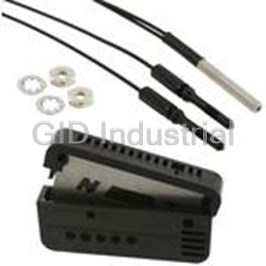
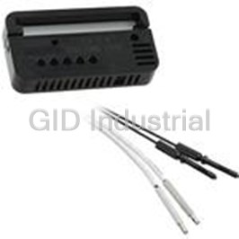
Photoelectric Sensor Thru-beam Light ON NPN 0.3m 2-Pin
E3T-ST212M
Part Number
E3T-ST212M
Price
Request Quote
Manufacturer
OMRON AUTOMATION
Lead Time
Request Quote
Category
Sensors and Transducers » Photoelectric Sensor
Specifications
Manufacturer
Omron Automation
Manufacturers Part #
E3T-ST212M
Sub-Category
Photoelectric Sensors
Factory Pack Quantity
1
Datasheet

Extracted Text
Miniature Square Photoelectric Sensor in plastic housing
E3T
• Precision pinpoint LED
3.5 mm thin flat shape or 6.6 mm side
view shape where space is crucial
IP67
Pulse synchronisation for high
ambient light immunity
Models for mounting with M2 or M3
screws
Features
3.5 mm flat model with background supression (BGS) with highest repeatability even for differently coloured
objects.
Minimal black/white error Unique light receiving lens shape New mounting technology for reliable background
for high precision alignment suppression in 3.5 mm flat housing
(mm)
Light receiving lens Light receiving
Flip chip (IC)
element
25
20
15
10
5
0
Rear Front Side
White paper Black paper
E3T-FL1@
Object detection through small holes
The precision pinpoint LED of the through-beam models
provides appropriate sensing distances for very precise and
reliable detection even through smallest slits and gaps with
e.g. 0.5 mm dia.
The coaxial optics and the small focal lens of the
retro-reflective models allow the detection of small
(dia 2 mm) objects or through small holes (dia 2 mm).
E3T 1
Application
E3T-SL limited-reflective models (side view) E3T-FD Diffuse-reflective Models (Flat)
Minimum detection object: 0.15 mm dia.Minimum detection object: 0.15 mm dia.
Limited-reflective optics reduce the influence of changing 3.5 mm thickness for installations with limited space.
backgrounds and surrounding metal for enhanced detec-
tion stability.
Models with M2 or M3 mounting holes
space saving M2 screw mounting
(screws included)
standard M3 screw mounting
(order screws sets from accessories)
2 Miniature Photoelectric Sensors
Ordering Information
Sensors
*1
Sensor type Connection method Order code
Mounting
Sensing Operation
screw
distance mode
NPN output PNP output
size
Through- 2 m ––2 m Light-ON M2 E3T-ST31 2M E3T-ST33 2M
beam
Dark-ON M2 E3T-ST32 2M E3T-ST34 2M
1 m Light-ON M2 E3T-ST11 2M E3T-ST13 2M
M3 E3T-ST11M 2M E3T-ST13M 2M
Dark-ON M2 E3T-ST12 2M E3T-ST14 2M
M3 E3T-ST12M 2M E3T-ST14M 2M
300 mm Light-ON M2 E3T-ST21 2M E3T-ST23 2M
M3 E3T-ST21M 2M E3T-ST23M 2M
Dark-ON M2 E3T-ST22 2M E3T-ST24 2M
M3 E3T-ST22M 2M E3T-ST24M 2M
Through- 500 mm Light-ON M2 E3T-FT11 2M E3T-FT13 2M
beam
Dark-ON M2 E3T-FT12 2M E3T-FT14 2M
300 mm Light-ON M2 E3T-FT21 2M E3T-FT23 2M
Dark-ON M2 E3T-FT22 2M E3T-FT24 2M
*2 *3 *3
Retro- 30 to 200 mm Light-ON M2 E3T-SR41-C 2M E3T-SR43-C 2M
*3 *3
reflective on reflectors/
Dark-ON M2 E3T-SR42-C 2M E3T-SR44-C 2M
*2
10 to 100 mm
on reflective
foils
Diffuse- 5 to 30 mm Light-ON M2 E3T-FD11 2M E3T-FD13 2M
reflective
M3 E3T-FD11M 2M E3T-FD13M 2M
Dark-ON M2 E3T-FD12 2M E3T-FD14 2M
M3 E3T-FD12M 2M E3T-FD14M 2M
Limited- 5 to 15 mm Light-ON M2 E3T-SL11 2M E3T-SL13 2M
reflective
M3 E3T-SL11M 2M E3T-SL13M 2M
Dark-ON M2 E3T-SL12 2M E3T-SL14 2M
M3 E3T-SL12M 2M E3T-SL14M 2M
5 to 30 mm Light-ON M2 E3T-SL21 2M E3T-SL23 2M
M3 E3T-SL21M 2M E3T-SL23M 2M
Dark-ON M2 E3T-SL22 2M E3T-SL24 2M
M3 E3T-SL22M 2M E3T-SL24M 2M
Diffuse- 1 to 15 mm Light-ON M2 E3T-FL11 2M E3T-FL13 2M
reflective
Dark-ON M2 E3T-FL12 2M E3T-FL14 2M
(back-
1 to 30 mm Light-ON M2 E3T-FL21 2M E3T-FL23 2M
ground
Dark-ON M2 E3T-FL22 2M E3T-FL24 2M
suppresion)
*1. For pre-wired models with robotic cables add '-R' to the order code (example: E3T-FT21R 2M)
*2. The distances are measured with reflector E39-R4 and reflective foil E39-R37-CA. For applications with shorter distances between the sensor and the reflector
contact your OMRON representative.
*3. Order reflector separately. Models with included reflectors are available.
E3T 3
For ordering pigtail versions replace '2M' of cable types with:
- M1J: M12 with 30 cm cable, - M3J: M8 4-pin with 30 cm cable
- M5J: M8 3-pin with 30 cm cable
Accessories (Order Separately)
Slits
Minimum detectable object (typical) Sensing distance Applicable sensor Quantity Order code
0.5mm dia 200 mm E3T-ST3 2 E39-S63
100 mm E3T-ST1
30 mm E3T-ST2
1mm dia 600 mm E3T-ST3
300 mm E3T-ST1
100 mm E3T-ST2
0.5mm dia 50 mm E3T-ST1 E39-S64
30 mm E3T-ST2
1mm dia 100 mm E3T-ST1
50 mm E3T-ST2
0.5mm dia 100 mm E3T-ST1_M E39-S67A
30 mm E3T-ST2_M
1mm dia 300 mm E3T-ST1_M E39-S67B
100 mm E3T-ST2_M
Mutual Interference Prevention Filters
Sensing distance Applicable sensor Quantity Order code
300 mm E3T-ST1_M 4 (two for receivers and two for emitters) E39-S67B
100 mm E3T-ST2_M
Reflectors
Minimum detectable
*1
Shape Type Sensing distance Remarks Order code
object (typical)
Small reflector 200 mm (30 mm) 2 mm dia E39-R4
100 mm (10 mm) Reflectors E39-_-CA E39-R37-CA
are optimised for opera-
tion with E3T-SR4.
Please verify the perfor-
Tape reflector 100 mm (10 mm) E39-RS1-CA
mance when using oth-
er reflectors and
100 mm (10 mm) E39-RS2-CA
reflective tapes.
100 mm (10 mm) E39-RS3-CA
*1. Values in parentheses indicate the minimum required distance between the Sensor and Reflector.
Sensitivity Adjustment Unit
Appearance Sensing distance (typical) Quantity Remarks Model
300 to 800 mm 1 Can be used with the E3T-ST1@ E39-E10
Though-beam Models.
4 Miniature Photoelectric Sensors
Mounting Brackets
Appearance Quantity Remarks Model
1 Can be used with the E3T-S@@@ E39-L116
Side-view Models.
(A securing nut plate is provided with the Mounting Bracket.)
E39-L117
for M2 mounting
E39-L166
for M3 mounting
E39-L118
Can be used with the E3T-F@@@ E39-L119
Flat Models.
E39-L120
for M2 mounting
E39-L167
for M3 mounting
Spacer for mounting flat sensors with M3 screws E39-L168
Note: When using Through-beam models, order one bracket for the Receiver and one for the Emitter.
Screw Sets
Type Comment Applicable sensor Quantity Order code
Screw set for M2 side view sensors Iron Phillips screws (M2×14), E3T-S 2 E39-L164
Hexagonal nuts, Spring washers,
Flat washers
Screw set for M2 flat sensors Iron Phillips screws (M2×8), E3T-F E39-L165
Hexagonal nuts, Spring washers,
Flat washers
SUS Screw set for M2 side view sen- Stainless steel bolt with hexagonal E3T-S E39-L172
sors hole (M2 x 6)
SUS Screw set for M2 flat sensors Stainless steel bolt with hexagonal E3T-F E39-L173
hole
(M2×12), Hexagonal nuts, Spring
washers, Flat washers
SUS Screw set for M3 side view sen- Stainless steel bolt with hexagonal E3T-S_M E39-L170
sors hole (M3 x 6)
SUS Screw set for M3 flat sensors Stainless steel bolt with hexagonal E3T-F_M E39-L171
hole
(M3×15), Hexagonal nuts, Spring
washers, Flat washers
E3T 5
Rating and Specifications
Through-beam Retro-reflective Diffuse-reflective
Side-view Flat Side-view Flat
Item
NPN PNP NPN PNP NPN PNP NPN PNP
E3T-ST1_ E3T-ST1_ E3T-FT1_ E3T-FT1_ E3T-SR41 E3T-SR43 E3T-FD11 E3T-FD13
E3T-FD12 E3T-FD14
E3T-ST2_ E3T-ST2_ E3T-FT2_ E3T-FT2_ E3T-SR42 E3T-SR44
Sensing distance E3T-ST1@ 1m E3T-FT1@ 500 mm 200 mm (30 mm) 5 to 30 mm
*1
E3T-ST2@ 300 mm E3T-FT2@ 300 mm with E39-R4 (50 x 50 mm white paper)
E3T-ST3@ 2m 100 mm (10 mm)
*1
with E39-R37-CA
Minimum detectable 2 mm dia opaque object 1.3 mm dia opaque object 2 mm dia. (sensing dis- 0.15 mm dia. (sensing
object (typical) (E3T-ST1 and E3T-ST2) tance of 100 mm) distance of 10 mm)
3 mm dia opaque object
(E3T-ST3)
Hysteresis (white paper) --- 6 mm max.
Directional angle Emitter: 2° to 20° Emitter: 3° to 25° 2° to 20° ---
Receiver: 2° to 70° Receiver: 3° min.
Light source Red LED (“Pin-point” LED) = 650 nm
(wavelength)
Power supply voltage 12 to 24 VDC ±10%, ripple (p-p) 10% max.
Current consumption Emitter: 10 mA max. 20 mA max.
Receiver: 20 mA max.
Control output Load power supply voltage: 26.4 VDC max.
Load current: 50 mA max.
(residual voltage: 2 V max. for load current of 10 to 50 mA, 1 V max. for load current of less than 10 mA)
Open collector output
Light ON: E3T-@@@1 and E3T-@@@3
Dark ON: E3T-@@@2 and E3T-@@@4
Protection circuits Power supply and control output reverse polarity Power supply and control Power supply and control
protection output reverse polarity output reverse polarity
Output short-circuit protection protection protection
Output short-circuit pro- Output short-circuit pro-
tection, Mutual interrefer- tection, Mutual interrefer-
ence prevention, surge ence prevention
suppressor
Response time Operate or reset: 1 ms max.
Ambient illumination Incandescent lamp: 5,000 lx max.
Sunlight: 10,000 lx max.
Ambient temperature Operating: -25 to 55 °C
range Storage: -40 to 70 °C (with no icing or condensation)
Ambient humidity range Operating: 35% to 85%
Storage: 35% to 95% (with no condensation)
Insulation resistance 20 M min. at 500 VDC
Dielectric strength 1,000 VAC, 50/60 Hz for 1 min
2
Vibration resistance Destruction: 10 to 2,000 Hz, 1.5 mm double amplitude or 300 m/s for 0.5 hrs each in X, Y, and Z directions
2
Shock resistance Destruction: 1,000 m/s 3 times each in X, Y, and Z directions
Degree of protection IP67 (IEC60529)
Connection method Pre-wired (standard length: 2 m)
Weight Approx. 40 g Approx. 20 g
Materials Case PBT (polybutylene terephthalate)
Display Denatured polyarylate
window
Lens Denatured polyarylate Methacrylic resin Denatured polyarylate
Accessories Instruction manual, (screw set E39-L164 for E3T-ST (2 sets) and E3T-SR (1 set); screw set E39-L165 for
E3T-FT (2 sets) and E3T-FS (1 set). For E3T-_M order screw sets separately)
*1. Values in parentheses indicate the minimum required distance between Sensor and Reflector.
6 Miniature Photoelectric Sensors
Limited-reflective Diffuse-reflective (background suppression)
Side-view Flat
Item
NPN PNP NPN PNP NPN PNP NPN PNP
E3T-SL11 E3T-SL13 E3T-SL21 E3T-SL23 E3T-FL11 E3T-FL13 E3T-FL21 E3T-FL23
E3T-SL12 E3T-SL14 E3T-SL22 E3T-SL24 E3T-FL12 E3T-FL14 E3T-FL22 E3T-FL24
Sensing distance 5 to 15 mm 5 to 30 mm 1 to 15 mm 1 to 30 mm
(50 x 50 mm white paper) (50 x 50 mm white paper) (50 x 50 mm white paper) (50 x 50 mm white paper)
Standard sensing object ---
Minimum detectable 0.15 mm dia. (sensing distance of 10 mm) 0.15 mm dia non-glossy object
object (typical) (sensing distance of 10 mm)
Hysteresis (white paper) 2 mm max. 6 mm max. 0.5 mm max. 2 mm max.
Black/white error --- 15% max.
Directional angle ---
Light source Red LED (“Pin-point” LED) = 650 nm
(wavelength)
Power supply voltage 12 to 24 VDC ±10%, ripple (p-p) 10% max.
Current consumption 20 mA max.
Control output Load power supply voltage: 26.4 VDC max.
Load current: 50 mA max. (residual voltage: 2 V max. for load current of 10 to 50 mA, 1 V max. for load current
of less than 10 mA)
Open-collector output
Light ON: E3T-@@@1 and E3T-@@@3
Dark ON: E3T-@@@2 and E3T-@@@4
Protection circuits Power supply and control output reverse polarity protection
Output short-circuit protection, Mutual interference prevention
Response time Operate or reset: 1 ms max.
Ambient illumination Incandescent lamp: 5,000 lx max.
Sunlight: 10,000 lx max.
Ambient temperature Operating: -25 to 55 °C
range Storage: -40 to 70 °C (with no icing or condensation)
Ambient humidity range Operating: 35% to 85%
Storage: 35% to 95% (with no condensation)
Insulation resistance 20 M min. at 500 VDC
Dielectric strength 1,000 VAC, 50/60 Hz for 1 min
2
Vibration resistance Destruction: 10 to 2,000 Hz, 1.5 mm double amplitude or 300 m/s for 0.5 hrs each in X, Y, and Z directions
2
Shock resistance Destruction: 1,000 m/s 3 times each in X, Y, and Z directions
Degree of protection IP67 (IEC60529)
Connection method Pre-wired (standard length: 2 m)
Weight Approx. 20 g
Materials Case PBT (polybutylene terephthalate)
Display Denatured polyarylate
window
Lens Denatured polyarylate
Accessories Instruction manual, (screw set E39-L164 for E3T-SL (1 set); screw set E39-L165 for E3T-FL (1 set). For
E3T-_M order screw sets separately)
E3T 7
Engineering Data (Typical)
M2-mounting and M3-mounting Sensors
Parallel Operating Range
Through-beam
E3T-ST3@ + E39-S63 Slit E3T-ST@@ + E39-E14 Mutual interference E3T-ST1@(M) + E39-S63 Slit
(A Slit is mounted to the Emitter and Receiver.) prevention filter (A Slit is mounted to the Emitter and Receiver.)
(A Slit is mounted to the Emitter and Receiver.)
200 100 200
Y
Without Slit
80
150 150
E3T-ST1@
X
Without Slit
60
0.5-dia
100 100
1-dia Slit
Slit
40
Y Y 0.5-dia Slit
50 50
20
X X
1.0-dia Slit
0 0 0
1.0 2.0 3.0 4.0 5.0 0.5 1.0 1.5 2.0 2.5 0.4 0.8 1.2 1.6 2.0
Distance X (m) Distance X (m)
Distance X (m)
−20
−50 −50
−40
−100 −100
−60
E3T-ST3@
−150 −150
−80
−200 −100 −200
E3T-ST1@(M) + E39-S63 Slit (Enlarged graph) E3T-ST2@(M) + E39-S63 Slit E3T-FT1@ + E39-S64 Slit
(A Slit is mounted to the Emitter and Receiver.) (A Slit is mounted to the Emitter and Receiver.) (A Slit is mounted to the Emitter and Receiver.)
80 25 200
Y
20
Y
60 150
Without Slit
X 15
X
Y
40 1-dia Slit 100
10
1-dia Slit 0.5-dia Slit
X
20 50
5
0.5-dia Slit
0.5-dia Slit
0
0 0
200 400 600 800 0.2 0.4 0.6 0.8 1 1.2 1.4
Without Slit
Distance X (mm) Distance X (m)
−5
−20 −50
40 80 120 160 200
Distance X (mm) −10
−40 −100
−15
1-dia Slit
−60 −150
−20
−80 −25 −200
E3T-FT1@ + E39-S64 Slit (Enlarged graph) E3T-FT2@ + E39-S64 Slit Retro-reflective
(A Slit is mounted to the Emitter and Receiver.) (A Slit is mounted to the Emitter and Receiver.) E3T-SR4@
80 80 40
1-dia Slit
Y Y
60
60 30
Without Slit
1-dia Slit X X
40
40 20
0.5-dia Slit
E3T-SR4@+E39-R4
Y
20
20 10
0.5-dia Slit
X
0
0
0
200 400 600 800
40 80 120 160 200
Distance X
Distance X (mm)
−20 −10
−20 (mm)
100 200 300 400
Distance X (mm)
E3T-SR4@+E39-R37-CA
−40 −20
−40
−60
−60 −30
−80
−80 −40
Operating Range
Diffuse-reflective Convergent-reflective
E3T-FD1@(M) E3T-SL1@(M) E3T-SL2@(M)
4 15 4
Sensing object: Sensing object:
X X
Sensing object: X
50 x 50 mm white paper
50 x 50 mm white paper
50 x 50 mm white paper
3 3
Y Y
Y
10
2 2
5
1 1
0 0
0
10 20 30 40
−1 −1
10 20 30 40
−5 Distance X (mm)
510152025 30
Distance X
−2 Distance X −2
(mm)
(mm)
−10
−3 −3
−4 −15 −4
8 Miniature Photoelectric Sensors
Distance Y (mm)
Distance Y (mm)
Distance Y (mm)
Distance Y (mm)
Distance Y (mm)
Distance Y (mm)
Distance Y (mm) Distance Y (mm)
Distance Y (mm) Distance Y (mm)
Distance Y (mm)
Distance Y (mm)
Inclination Detection Area Characteristic
BGS-reflective Convergent-reflective
E3T-FL1@ E3T-FL2@ E3T-SL1@(M) (Top to Bottom)
20
5 10
4 8 Stainless steel
3 6
Glass
Sensing object:
X
Sensing object: X
2 4 t: 0.7 mm
50 x 50 mm white paper
50 x 50 mm white paper
Y
Y
1 2
10
0 0
2 6 4 10 8 12 14 16 5 15 10 25 20 30 35
Distance X (mm)
Distance X (mm)
−1 −2
Angle of
−2 −4
inclination
+θ −θ
−3 −6
−4 −8
0
−5 −10 −10 0 10
Angle θ (°)
E3T-SL1@(M) (Right to Left) E3T-SL2@(M) (Top to Bottom) E3T-SL2@(M) (Right to Left)
20
40 40
Stainless steel
Stainless steel
30 30
Glass
t: 0.7 mm Angle of
10 20 20
+θ −θ
inclination
Stainless steel
10 10
Glass
Angle of
t: 0.7 mm
Angle of
+θ −θ inclination
Glass
+θ −θ inclination
t: 0.7 mm
0 0
0
−10 0 10 −10 0 10 −10 0 10
Angle θ (°) Angle θ (°) Angle θ (°)
BGS-reflective
E3T-FL1@ (Top to Bottom) E3T-FL1@ (Right to Left) E3T-FL2@ (Top to Bottom)
20 20 40
Angle of
Angle of
Angle of
inclination
inclination
inclination
+θ +θ
+θ
White paper −θ White paper −θ
30 White
−θ
Center Center
Center
paper
line line
line
10 20
10
Glass
t: 0.7 mm
Glass Glass
t: 0.7 mm
t: 0.7 mm 10
Stainless steel
Stainless steel
Stainless steel
0 0 0
−10 0 10 −10 0 10 −10 0 10
Angle θ (°) Angle θ (°) Angle θ (°)
Excess Gain vs. Set Distance
Through-beam
E3T-FL2@ (Right to Left) E3T-ST1@(M)/E3T-ST3@ E3T-ST2@(M)
40 100 14
Angle of
inclination
50
12
+θ
30
White paper −θ
30 Center
10
E3T-ST3@
line
10
8
5
20
3
6
E3T-ST1@(M)
Operating
level 1
Glass 4
10 t: 0.7 mm
0.5
0.3
2
Operating
Stainless steel 1
level
0.1
0 0
0 300 600 900 1200
−10 0 10 0 1000 2000 3000 4000
Angle θ (°)
Set distance (mm) Set distance (mm)
E3T 9
Distance (mm) Distance (mm) Distance (mm)
Distance Y (mm)
Distance (mm) Distance (mm)
Distance Y (mm)
Excess gain ratio
Distance (mm) Distance (mm)
Distance (mm)
Excess gain ratio
Retro-reflective
E3T-FT1@ E3T-FT2@ E3T-SR4@
14 100
100
50
50
12
30
30
10 E3T-SR4@+E39-R4
10
10
8
5
5
3
3
6
Operating
Operating E3T-SR4@+E39-R37-CA
level 1
1
level
4
0.5
0.5
0.3
0.3 2
Operating
level 1
0.1
0
0.1
0 400 800 1200 1600 2000 0 500 1000 1500 2000 0 100 200 300
Set distance (mm) Set distance (mm)
Set distance (mm)
Diffuse-reflective Convergent-reflective
E3T-FD1@(M) E3T-SL1@(M) E3T-SL2@(M)
100
100 1000
500
50
50
300
30
30
100
10 50 10
White paper
30
White paper
White paper 5
5
3
3 10
5
Operating Operating
3
1 1
level level
Operating
1
level 0.5
0.5
Black paper
0.5
0.3 0.3
Black paper
0.3
Black paper
0.1 0.1
0.1
0 10 20 30 40
0 10 20 30 40 0 5 10 15 20
Set distance (mm)
Set distance (mm)
Set distance (mm)
Sensing Object Size vs. Sensing Distance Sensing Distance vs. Material
Convergent-reflective Diffuse/Convergent-reflective Convergent-reflective
E3T-SL1@(M) E3T-FD1@(M)/E3T-SL2@(M) E3T-SL1@(M)
2.0 10
25
Sensing object: Pin-gauge, stainless steel
20
1.6 8
6 15
1.2
E3T-FD1@(M)
4 10
0.8
2 5
0.4
E3T-SL2@(M)
0
0 5 10 15 20 0 5 10 15 20 25 30
Set distance (mm)
Set distance (mm)
Material
Diffuse-reflective BGS-reflective
E3T-SL2@(M) E3T-FD1@(M) E3T-FL1@
50 70 20
60
40
15
50
30
40
10
30
20
20
5
10
10
0
0
0
Material Material Material
10 Miniature Photoelectric Sensors
Min. sensing object dia. (mm)
Excess gain ratio
Excess gain ratio
Sensing distance (mm)
White
paper
Stainless
Plywood
Cardboard
Glass
sheet
Black
rubber
Black
paper
Excess gain ratio
Min. sensing object dia. (mm)
Sensing distance (mm)
Excess gain ratio
White
paper
Stainless
Plywood
Cardboard
Glass
sheet
Black
rubber
Black
paper
Sensing distance (mm) Excess gain ratio
Sensing distance (mm) Excess gain ratio
White White
paper paper
Stainless Stainless
Plywood Plywood
Cardboard Cardboard
Glass Glass
sheet sheet
Black
Black
rubber rubber
Black
Black
paper paper
Sensing Distance Characteristics of Sensitivity Adjustment Unit
(when Completing Optical Axis Adjustment)
E3T-ST1@ + E39-E10 Sensitivity Adjustment Unit
E3T-FL2@
E3T-ST3@ + E39-E10 Sensitivity Adjustment Unit
40 3.5
3.0
30
2.5
E3T-ST3@
2.0
20
1.5
1.0
10
E3T-ST1@
0.5
0
0
Min 1/3 1/2 2/3 Max
Adjustment dial angle
Material
I/O Circuit Diagrams
NPN Output
Model Operation mode Timing charts Output circuit
Light incident
Light interrupted Through-beam Receivers,
Retroreflective and Reflective Models
12 to 24 VDC
Operation Brown
ON
1
Operation Stability
indicator
OFF
(orange) indicator indicator
Load
E3T-_1
(Orange) (Green)
(Control
Light-ON (Relay)
ON 50 mA
Output
E3T-_1M output)
max.
transistor Photo-
OFF
4
electric
Black
Sensor
ZD
Operate Main
Load
Blue
Circuit
3
(e.g., relay) Reset
0 V
(Between brown and black)
Light incident
Through-beam Emitters
Light interrupted
Brown
Operation
ON 1
indicator
OFF
Photo-
(orange)
E3T-_2
electric
Dark-ON
Sensor 12 to 24 VDC
ON
Output
E3T-_2M
Main
transistor
OFF Circuit
Blue
3
Operate
Load
(e.g., relay) Reset
(Between brown and black)
PNP Output
Model Operation mode Timing charts Output circuit
Light incident
Light interrupted
Through-beam Receivers,
Retroreflective and Reflective Models
Operation
ON Brown 12 to 24 VDC
indicator
1
Operation Stability
OFF
(orange)
indicator indicator
E3T-_3
(Orange) (Green)
Light-ON
ZD
ON
Output
E3T-_3M
transistor Black
OFF
Photo-
4
electric
(Control
Load
50 mA
Sensor
Operate output)
Load
Main (Relay)
max.
(e.g., relay) Circuit
Reset
3
Blue 0 V
(Between blue and black leads)
Light incident
Light interrupted Through-beam Emitters
Brown
Operation
ON
1
indicator
OFF
(orange)
Photo-
E3T-_4
electric
Dark-ON
ON
Output
Sensor
E3T-_4M
12 to 24 VDC
transistor Main
OFF
Circuit
Blue
Operate
Load 3
(e.g., relay) Reset
(Between blue and black leads)
E3T 11
Sensing distance (mm)
White
paper
Stainless
Plywood
Cardboard
Glass
sheet
Black
rubber
Black
paper
Sensing distance (m)
Safety Precautions
Refer to Warranty and Limitations of Liability.
Adjusting
WARNING
Indicators
This product is not designed or rated for ensuring The following graphs indicate t he status of each operating level.
safety of persons. Do not use it for such purpose.Be sure to use the E3T within the stable operating range.
Stability
Operation indicator (orange)
indicator
E3T-@@@1 E3T-@@@2
Do not apply AC power to the E3T, otherwise the E3T
(green)
E3T-@@@3
E3T-@@@4
may rupture.
Stable
ON
operation
*
range ON OFF
Operating
level x 1.2
Precautions for Correct Use
Unstable
OFF
Operating
operation
level
Do not use the product in atmospheres or environments that exceed
*
range
Operating
product ratings.
level x 0.8
OFF ON
Stable
ON
Wiring
operation
*
range
The maximum power supply voltage is 26.4 VDC. Before turning the
power ON, make sure that the power supply voltage be not more than
*
If the E3T fs operating level is set to the stable operation range, the
maximum voltage.
E3T will be in most reliable operation without being influenced by
temperature change, voltage fluctuation, dust, or setting change. If
Load short-circuit protection
the operating level cannot be set to the stable operation range, pay
attention to environmental changes while operating the E3T.
The E3T incorporates a load short-circuit protection function. If the
load short-circuits, the output of the E3T will be turned OFF. Then,
Use of E39-E10 Sensitivity Adjustment Unit
recheck the wiring and turn on the E3T again to reset the load short-
(Dark-ON: E3T-ST12)
circuit protection function. The load short-circuit protection function
will work if there is a current flow that is 1.5 times larger than the rated
(At Min) (At Center) (At Max.)
load current. When using a capacitance load, be sure that the inrush
Indicator
current will not exceed 1.5 times larger than the rated current.
Adjuster
Mounting
When mounting the Sensor, never strike it with a heavy object, such
as a hammer. Doing so may reduce its watertight properties. Use
screws with spring, flat, or toothed washers to secure the Sensor.
Tightening Torque
1. Mount the Unit on the Receiver.
M2-mounting Sensors: 0.15 N·m max
2. Set the adjuster of the Sensitivity Adjustment Unit to Max.
M3-mounting Sensors: 0.5 N·m max
(Before shipping: Max.)
3. After mounting on the Sensor, adjust the optical axis and secure
Mounting the Sensor on Moving Parts
the Sensor.
Consider models that use break
B
4. Place a workpiece between the Emitter and Receiver and
resistant cables (e.g., Robotics
gradually turn the adjuster counterclockwise toward the Min. side.
Cables) if the Sensor will be
Stop turning the adjuster when the operation indicator and stability
mounted on a moving part, such as a A C
indicator (green) turn ON.
robot hand. The flexing resistance of
5. Remove the workpiece and confirm that the operation indicator is
θ θ
Robotics Cable at approximately
OFF and the stability indicator (green) is ON. This completes the
400 thousand times is far superior to
adjustment.
that of standard cable at
R
Note: If the light attenuation rate due to a workpiece is 40% or less, the stability
approximately 14 thousand times.
indicator will not turn ON whether or not light is received. When the
variation of light is small such as when sensing semi-transparent
Cable Bending Rupture Test
workpieces, carefully perform preliminary testing.
(Tough Cable Breaking Test)
The cable is repeatedly bent with
Others
power supplied to check the number
Weight Do not install the E3T in the following locations.
of bends until the current is turned Locations subject to excessive dust or dirt
OFF.Locations subject to direct sunlight
Locations subject to corrosive gas
Specimen Standard cable Robotics cable
Locations subject to co ntact with organic solvents
2.4-mm dia. 2.4-mm dia.
(7/0.127-mm dia.), (20/0.08-mm dia.), Locations subject to vibration and shock
Test 3 conductors 3 conductors
Locations subject to contact wi th water, oil, or chemicals
Bending angle () 90 each to the left and rightLocations subject to high humiditie s that might result in condensa-
Bending speed 50 times/min
tion
Con-
tents/ Load 200 g
condi-
Operation per bend Once in 1 to 3 in the diagram
tions
Curvature radius of
5 mm
support point (R)
Result Approx. 14,000 times Approx. 400,000 times
12 Miniature Photoelectric Sensors
Light
Dimensions
(Unit: mm)
Tolerance class IT16 applies to dimensions in this datasheet unless otherwise specified.
Sensors
M2-mounting Sensors
Through-beam Side-view Sensors
E3T-ST1@ (Emitter)
E3T-ST2@ (Emitter)
7 9 9.5 .5
Mounting Holes
E3T-ST3@ (Emitter)
7.7
3.8 Two, M2 holes
2.7
Emitter 14.6 14.6
9
±0.2
lens 9
(1.3 dia.)
Two, 2.2 dia.
3.9
2.4-dia. vinyl-insulated round cable
with 2 conductors (Conductor cross
2.2
section: 0.1 mm² (AWG27),
Insulator diameter: 0.7 mm),
Emitter: E3T-ST@@-L
4.8
Standard length: 2 m
Receiver: E3T-ST@@-D
M12 Smartclick Pre-wired Connector Model
(E3T-ST@@-M1TJ/E3T-FT@@-M1TJ)
E3T-ST1@ (Receiver)
2 1
E3T-ST2@ (Receiver)
E3T-ST3@ (Receiver)
3
4
7
9.5
Operation Stability
Mounting Holes
M12
indicator indicator 7.7
2.4-dia. vinyl-insulated round cable
Two, M2 holes
with 2 or 3 conductors
3.8
Standard length: 0.3 m
2.7
14.6
9 9±0.2
Receiver
*
*
The receiver lens diameters are lens
e-CON Pre-wired Connector Model
given below.
(E3T-ST@@-ECON/E3T-FT@@-ECON)
Two, 2.2 dia. 3.9
Receiver lens
Model
diameter 5.9
2.4-dia. vinyl-insulated round cable
with 3 conductors (Conductor cross
1
2.2
E3T-ST1@-D
section: 0.1 mm² (AWG27), 2
(1.3 dia.)
15
E3T-ST2@-D
Insulator diameter: 0.7 mm),
4.8 3
Standard length: 2 m 4
E3T-ST3@-D (2.4 dia.)
15.6
2.4-dia. vinyl-insulated round cable
with 2 or 3 conductors
Standard lengths: 0.3 m and 2 m
Through-beam Flat Sensors
E3T-FT1@ (Emitter)
E3T-FT2@ (Emitter)
Termi- Specifica-
12 12 3.5 3.5
nal No. tions
Mounting Holes
1+V
Emitter
Two, M2 holes
2 ---
lens
14
(1.3 dia.) 15.8 15.8
30 V
8.6
Output
8±0.2
4
(receiver only)
Two, 2.2 dia.
3.2
2.4-dia. vinyl-insulated round cable
with 2 conductors (Conductor cross
1.75 1.75
4.4
section: 0.1 mm² (AWG27), * Refer to
Frequently asked questions
How does Electronics Finder differ from its competitors?

Is there a warranty for the E3T-ST212M?
Which carrier will Electronics Finder use to ship my parts?
Can I buy parts from Electronics Finder if I am outside the USA?
Which payment methods does Electronics Finder accept?
Why buy from GID?

Quality
We are industry veterans who take pride in our work

Protection
Avoid the dangers of risky trading in the gray market

Access
Our network of suppliers is ready and at your disposal

Savings
Maintain legacy systems to prevent costly downtime

Speed
Time is of the essence, and we are respectful of yours
Related Products
Photoelectric Sensor Thru-beam 1.15m E32A0311M
Photoelectric Sensor Thru-beam 1.15m E32A032M
Photoelectric Sensor Thru-beam 1.15m E32-A034.5M
Photoelectric Sensor Thru-beam 0.46m E32A0412M
Photoelectric Sensor Thru-beam 0.46m E32-A04-2M
Photoelectric Sensor Thru-beam 0.46m E32A0462M
Request a Quote

The quote request has been received
Close

Facing challenges or have inquiries? Feel free to contact us!
Call Us +1-469-283-2440
What they say about us
FANTASTIC RESOURCE
One of our top priorities is maintaining our business with precision, and we are constantly looking for affiliates that can help us achieve our goal. With the aid of GID Industrial, our obsolete product management has never been more efficient. They have been a great resource to our company, and have quickly become a go-to supplier on our list!
Bucher Emhart Glass
EXCELLENT SERVICE
With our strict fundamentals and high expectations, we were surprised when we came across GID Industrial and their competitive pricing. When we approached them with our issue, they were incredibly confident in being able to provide us with a seamless solution at the best price for us. GID Industrial quickly understood our needs and provided us with excellent service, as well as fully tested product to ensure what we received would be the right fit for our company.
Fuji
HARD TO FIND A BETTER PROVIDER
Our company provides services to aid in the manufacture of technological products, such as semiconductors and flat panel displays, and often searching for distributors of obsolete product we require can waste time and money. Finding GID Industrial proved to be a great asset to our company, with cost effective solutions and superior knowledge on all of their materials, it’d be hard to find a better provider of obsolete or hard to find products.
Applied Materials
CONSISTENTLY DELIVERS QUALITY SOLUTIONS
Over the years, the equipment used in our company becomes discontinued, but they’re still of great use to us and our customers. Once these products are no longer available through the manufacturer, finding a reliable, quick supplier is a necessity, and luckily for us, GID Industrial has provided the most trustworthy, quality solutions to our obsolete component needs.
Nidec Vamco
TERRIFIC RESOURCE
This company has been a terrific help to us (I work for Trican Well Service) in sourcing the Micron Ram Memory we needed for our Siemens computers. Great service! And great pricing! I know when the product is shipping and when it will arrive, all the way through the ordering process.
Trican Well Service
GO TO SOURCE
When I can't find an obsolete part, I first call GID and they'll come up with my parts every time. Great customer service and follow up as well. Scott emails me from time to time to touch base and see if we're having trouble finding something.....which is often with our 25 yr old equipment.
ConAgra Foods