

 Manufacturers
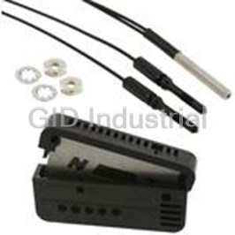
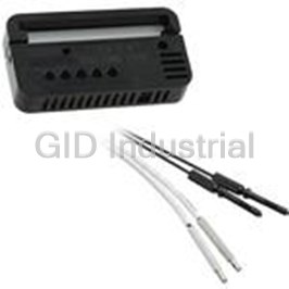
OMRON AUTOMATION E3Z-LR612M

Description
Photoelectric Sensor Retro-Reflective Light ON/Dark ON NPN 15m 4-Pin
E3Z-LR612M
Part Number
E3Z-LR612M
Price
Request Quote
Manufacturer
OMRON AUTOMATION
Lead Time
Request Quote
Category
Sensors and Transducers » Photoelectric Sensor
Specifications
Manufacturer
Omron Automation
Manufacturers Part #
E3Z-LR612M
Industry Aliases
E3ZLR612M
Sub-Category
Photoelectric Sensors
Factory Pack Quantity
1
Datasheet

Extracted Text
Compact Laser Photoelectric Sensor with Built-in Amplifier E3Z-LT/LR/LL CSM_E3Z-LT_LR_LL_DS_E_6_8 Compact and Reliable Laser Photoelectric Sensor • Safety and reliability with laser class 1 (JIS and IEC). Product lineup includes models with distance setting without influence of color. Maximum ambient operating temperature of 55 °C and water- proof construction in E3Z class. For the most recent information on models that have been certified for Be sure to read Safety Precautions on safety standards, refer to your OMRON website. page 9. Applications Detect the sides of large tiles. Count bottles. Greatly Enhanced Beam Visibility Reliable Detection of for Easier Optical Axis Adjustment of Sensors Small Objects and Narrow Gaps with the Small Spot Detect chip components on tape. Detect protruding straws. Long-distance Sensing A Low Black/White Error for at 300 mm (White Paper) Applications with Mixed Colors 1 E3Z-LT/LR/LL Ordering Information Sensors (Refer to Dimensions on page 11.) Red light Model Connection Response Sensing method Appearance Sensing distance method time NPN output PNP output E3Z-LT61 2M E3Z-LT81 2M Pre-wired Emitter E3Z-LT61-L 2M Emitter E3Z-LT81-L 2M (2 m) Receiver E3Z-LT61-D 2M Receiver E3Z-LT81-D 2M Through-beam 60 m (Emitter + Receiver) E3Z-LT66 E3Z-LT86 Connector Emitter E3Z-LT66-L Emitter E3Z-LT86-L (M8, 4 pins) Receiver E3Z-LT66-D Receiver E3Z-LT86-D *2 Pre-wired 15 m E3Z-LR61 2M E3Z-LR81 2M (2 m) (300 mm) (Using E39-R1) Retro-reflective with 1 ms 7 m MSR function (200 mm) (Using E39-R12) *1 Connector 7 m E3Z-LR66 E3Z-LR86 (M8, 4 pins) (200 mm) (Using E39-R6) Pre-wired 20 to 40 mm E3Z-LL61 2M E3Z-LL81 2M (2 m) (Min. distance set) Connector 20 to 300 mm E3Z-LL66 E3Z-LL86 (M8, 4 pins) (Max. distance set) Distance-settable (BGS Models) Pre-wired 25 to 40 mm E3Z-LL63 2M E3Z-LL83 2M (2 m) (Min. distance set) 0.5 ms Connector 25 to 300 mm E3Z-LL68 E3Z-LL88 (M8, 4 pins) (Max. distance set) *1. The Reflector is sold separately. Select the Reflector model most suited to the application. *2. Values in parentheses indicate the minimum required distance between the Sensor and Reflector. Accessories Slits (A Slit is not provided with a Through-beam Sensor. Order a Slit separately if required.) (Refer to Dimensions on page 14.) Minimum detectable object Slit width Sensing distance Model Contents (reference value) One set 0.5 mm dia. 3 m 0.1 mm dia. E39-S65A (contains Slits for both the Emitter and Receiver) Reflectors (A Reflector is required for each Retro-reflective Sensor: A Reflector is not provided with the Sensor. Be sure to order a Reflector.) (Refer to Dimensions on page 14.) Sensing distance Name Model Remarks Rated value Reference value --- 15 m (300 mm) E39-R1Retro-reflective models are not provided with Reflectors. Separate the Sensor and the Reflector by at least the --- Reflector 7 m (200 mm) E39-R12 distance given in parentheses. --- 7 m (200 mm) E39-R6The MSR function is enabled. Note: If you use the Reflector at any distance other than the rated distance, make sure that the stability indicator lights properly when you install the Sensor. 2 E3Z-LT/LR/LL Mounting Brackets A Mounting Bracket is not provided with the Sensor. Order a Mounting Bracket separately if required. (Refer to Dimensions on E39-L/E39-S/E39-R.) Appear- Appear- Model Quantity Remarks Model Quantity Remarks ance ance E39-L153 E39-L98 1 1 Metal Protective Cover Bracket *1 *2 Mounting Brackets E39-L104 1 E39-L150 1 set *1 (Sensor adjuster) Easily mounted to the aluminum E39-L43 1 Horizontal Mounting Bracket frame rails of conveyors and *2 easily adjusted. E39-L151 1 set For left to right adjustment E39-L142 Horizontal Protective Cover 1 Bracket *2 E39-L144 Compact Protective Cover E39-L44 1 Rear Mounting Bracket 1 Bracket (For E3Z only) *2 Note: When using a Through-beam Sensor, order one Mounting Bracket for the Receiver and one for the Emitter *1. Cannot be used for Standard Connector models with mounting surface on the bottom. In that case, use Pre-wired Connector models. *2. Cannot be used for Standard Connector models. Sensor I/O Connectors (Sockets on One Cable End) (Models for Connectors and Pre-wired Connectors: A Connector is not provided with the Sensor. Be sure to order a Connector separately.) (Refer to Dimensions on XS3) Size Cable Appearance Cable type Model 2 m XS3F-M421-402-A Straight *1 5 m XS3F-M421-405-A M8 Standard 4-wire 2 m XS3F-M422-402-A L-shaped *1 *2 5 m XS3F-M422-405-A Note: When using a Through-beam Sensor, order one Mounting Bracket for the Receiver and one for the Emitter *1. The connector will not rotate after connecting. *2. The cable is fixed at an angle of 180° from the sensor emitter/receiver surface. 3 E3Z-LT/LR/LL Ratings and Specifications Sensing Retro-reflective with MSR Through-beam Distance-settable (BGS models) method function Response Standard response High-speed response NPN E3Z-LT61/-LT66 E3Z-LR61/-LR66 E3Z-LL61/-LL66 E3Z-LL63/-LL68 output Model PNP Item E3Z-LT81/-LT86 E3Z-LR81/-LR86 E3Z-LL81/-LL86 E3Z-LL83/-LL88 output White paper (100 × 100 mm): White paper (100 × 100 mm): 0.2 to 7 m 20 to 300 mm 25 to 300 mm Sensing distance 60 m (when using E39-R12) Black paper (100 × 100 mm): Black paper (100 × 100 mm): 20 to 160 mm 25 to 100 mm White paper (100 × 100 mm): White paper (100 × 100 mm): 40 to 300 mm 40 to 300 mm Set distance range --- Black paper (100 × 100 mm): Black paper (100 × 100 mm): 40 to 160 mm 40 to 100 mm Spot diameter 5-mm dia. at 3 m 0.5-mm dia. at 300 mm (reference value) Standard sensing object Opaque: 12-mm dia. min. Opaque: 75-mm dia. min. --- Minimum detectable object 6-mm-dia. opaque object at 3 m 0.2-mm-dia. stainless-steel pin gauge at 300 mm (reference value) Differential travel --- 5% max. of set distance Black/white error --- 5% at 160 mm 5% at 100 mm Directional angle Receiver: 3 to 15° --- Light source (wavelength) Red LD (655 nm), JIS CLass 1, IEC Class 1, FDA Class 2 Power supply voltage 12 to 24 VDC±10%, ripple (p-p): 10% max. 35 mA (Emitter 15 mA, Current consumption 30 mA max. Receiver 20 mA) Control output Load power supply voltage: 26.4 VDC max., Load current: 100 mA max., Open collector output Load current of less than 10 mA: 1 V max. Residual output voltage Load current of 10 to 100 mA: 2 V max. Output mode switching Switch to change between light-ON and dark-ON Reversed power supply polarity protection, Output Reversed power supply polarity protection, Output short-circuit protection, Mutual interference pre- Protection circuits short-circuit protection, and vention, and Reversed output polarity protection Reversed output polarity protection Response time Operate or reset: 1 ms max. Operate or reset: 0.5 ms max. Sensitivity adjustment One-turn adjuster Five-turn endless adjuster Ambient illumination Incandescent lamp: 3,000 lx max. Sunlight: 10,000 lx max. (Receiver side) Ambient temperature range Operating: −10 to 55°C, Storage: −25 to 70°C (with no icing or condensation) Ambient humidity range Operating: 35% to 85%, Storage: 35% to 95% (with no icing or condensation) Insulation resistance 20 MΩ min. at 500 VDC Dielectric strength 1,000 VAC, 50/60 Hz for 1 min Vibration resistance Destruction: 10 to 55 Hz, 1.5-mm double amplitude for 2 hours each in X, Y, and Z directions 2 Shock resistance Destruction: 500 m/s 3 times each in X, Y, and Z directions Degree of protection IP67 (IEC 60529) Pre-wired cable (standard length: 2 m): E3Z-L@@1/-L@@3 Connection method Standard M8 Connector: E3Z-L@@6/-L@@8 Operation indicator (orange) Indicator Stability indicator (green) Emitter for Through-bream Models has power indicator (orange) only. Pre-wired cable Approx. 120 g Approx. 65 g Weight (2 m) (packed Standard state) Approx. 30 g Approx. 20 g Connector Case PBT (polybutylene terephthalate) Material Lens Modified polyarylate resin Methacrylic resin Modified polyarylate resin Accessories Instruction manual (Neither Reflectors nor Mounting Brackets are provided with any of the above models.) 4 E3Z-LT/LR/LL Engineering Data (Reference Value) Parallel Operating Range Through-beam Models Through-beam Models Retro-reflective Models E3Z-LT@@ + E39-S65A E3Z-LT@@ E3Z-LR@@ 150 20 60 E39-R1 15 Y 100 40 X 10 E39-R6 50 20 5 0 0 0 2 46 8 10 20 40 60 80 5 10 15 20 25 30 −5 −50 −20 Y −10 E39-R12 X −100 −40 −15 −20 −150 −60 Distance X (m) Distance (m) Distance X (m) Operating Range at a Set Distance Operating Range at a Set Distance of 300 mm of 40 mm BGS Models BGS Models E3Z-LL@@ E3Z-LL@@ 2.50 3 2.00 Y Sensing object: 2 1.50 100 × 100 mm white paper X Y 1.00 Sensing object: 1 100 × 100 mm white paper 0.50 X 0.00 0 0 50 100 150 200 350 10 20 30 40 50 60 250 300 −0.50 −1 −1.00 −1.50 −2 −2.00 −2.50 −3 Distance X (mm) Distance X (mm) Excess Gain vs. Set Distance Through-beam Models Retro-reflective Models E3Z-LT@@ E3Z-LR@@ 10000 100 E39-R1 10 1000 E39-R12 1 E39-R6 100 0.1 02 100 30 40 50 60 70 80 0 10 20 30 Distance (m) Distance (m) Close Range Characteristics BGS Models E3Z-LL@3/-LL@8 E3Z-LL@1/-LL@6 350 350 300 mm 300 mm 300 300 250 250 200 200 160 mm 150 150 100 mm 100 100 40 mm 40 mm 40 mm 40 mm 50 50 10 mm 12 mm 0 mm 9 mm 10 mm 21 mm 0 mm 9 mm 0 0 White Black White Black White Black White Black paper paper paper paper paper paper paper paper Setting: Setting: Setting: Setting: Setting: Setting: Setting: Setting: 300 mm 160 mm 40 mm 40 mm 300 mm 100 mm 40 mm 40 mm 5 Operating range Y (mm) Excess gain ratio (multiple) Distance Y (mm) Sensing distance (mm) Sensing distance (mm) Operating range Y (mm) Distance (mm) Excess gain ratio (multiple) Distance Y (mm) E3Z-LT/LR/LL Sensing Distance vs. Sensing Object Material BGS Models E3Z-LL@1/-LL@6 E3Z-LL@3/-LL@8 E3Z-LL@1/-LL@6 White Paper with a Set Distance of 40 mm White Paper with a Set Distance of 40 mm White Paper with a Set Distance of 300 mm 50 50 350 300 40 40 250 30 30 200 150 20 20 100 10 10 50 0 0 0 White Veneer Card- Black Black SUS Mirror White Veneer Card- Black Black SUS Mirror White Veneer Card- Black Black SUS Mirror rubber rubber paper board paper surface paper board paper surface paper board paper rubber surface Material Material Material Emission Spot Diameter vs. Distance Through-beam and Retro-reflective BGS Models (Same for All Models) Models (Same for All Models) E3Z-LL@3/-LL@8 E3Z-LT@@, E3Z-LR@@ E3Z-LL@@ White Paper with a Set Distance of 100 mm 120 100 1.4 90 a 1.2 100 80 Dimension a b 1.0 70 Spot shape 80 60 0.8 50 60 Dimension a Dimension b 0.6 40 40 30 a 0.4 20 Dimension b b 0.2 20 10 Spot shape 0 0 0 0 10 20 30 40 50 60 0 100 200 300 400 500 600 White Veneer Card- Black Black SUS Mirror Set distance (m) Set distance (mm) paper board paper rubber surface Material Hysteresis vs. Distance BGS Models E3Z-LL@1 (LL@6) E3Z-LL@3 (LL@8) 2.50 2.50 2.00 2.00 Black paper Black paper 1.50 1.50 1.00 1.00 White White paper paper 0.50 0.50 0.00 0.00 0 100 200 300 400 0 100 200 300 400 Set distance (mm) Set distance (mm) Inclination Characteristics (Vertical) Inclination Characteristics (Horizontal) BGS Models BGS Models E3Z-LL@@ E3Z-LL@@ 20 20 Distance setting: 300 mm Distance setting: 300 mm Sensing object: White paper 15 15 Sensing object: White paper 100 × 100 mm 100 × 100 mm 10 10 5 5 0 0 (Upwards (Left and −5 and −5 Right) Downwards) Inclination Inclination angle −10 −10 angle + θ + θ − θ −15 −15 − θ Sensing Sensing Center Center object object line line −20 −20 −40 −30 −20 −10 0 102030 40 −40 −30 −20 −10 0 102030 40 Inclination angle θ (°) Inclination angle θ (°) 6 Sensing distance variation (%) Sensing distance (mm) Sensing distance (mm) Sensing distance variation (%) Spot diameter (mm) Sensing distance (mm) Spot diameter (mm) Sensing distance (mm) Hysteresis (%) Hysteresis (%) E3Z-LT/LR/LL I/O Circuit Diagrams NPN Output Operation Operation Model Timing charts Output circuit mode selector Light incident Through-beam Receivers, Retro-reflective Models Light interrupted 12 to 24 VDC Brown ON Operation 1 Operation indicator Stability (orange) OFF indicator L side indicator Load Light-ON ON (Control (Relay) Output transistor (Green) 100 mA (LIGHT ON) (Orange) OFF output) max. Photo- 4 Load Operate electric Black (e.g., relay) Reset Sensor Z D (Between brown A and black D leads) Main Blue Circuit 3 Light incident 0 V Light interrupted M8 4-pin Connector Operation indicator ON E3Z-LT61 * Pin Arrangement (orange) OFF D side E3Z-LT66 * Dark-ON ON 2 4 Output transistor (DARK ON) OFF 1 3 E3Z-LR61 Load Operate E3Z-LR66 (e.g., relay) Reset (Between brown A and black D leads) Pin 2 is not used. Through-beam Emitter M8 4-pin Connector Brown Power 1 Pin Arrangement indicator (orange) 2 4 Photo- 1 3 12 to 24 VDC electric Sensor Main Circuit Blue Pins 2 and 4 3 are not used. NEAR FAR 12 to 24 VDC Brown Operation 1 ON Operation indicator Stability (orange) indicator OFF Load indicator L side (Control ON (Relay) Light-ON Output 100 mA (Green) (Orange) output) transistor (LIGHT ON) OFF max. Photo- 4 Load electric Operate E3Z-LL61 Black (e.g., relay) Sensor Reset Z D Main Blue E3Z-LL66 (Between brown A and black D leads) Circuit 3 0 V E3Z-LL63 NEAR FAR Operation M8 4-pin Connector E3Z-LL68 indicator ON Pin Arrangement (orange) OFF D side 2 4 Output ON Dark-ON 1 3 transistor OFF (DARK ON) Load Operate (e.g., relay) Reset Pin 2 is not used. (Between brown A and black D leads) PNP Output Operation Operation Model Timing charts Output circuit mode selector Light incident Through-beam Receivers, Retro-reflective Models Light interrupted Brown 12 to 24 VDC Operation indicator ON 1 Operation (orange) OFF L side Stability indicator Light-ON indicator ON Output transistor Z D (LIGHT ON) (Green) OFF (Orange) Black Load Operate Photo- 4 (e.g., relay) Reset electric (Control Load 100 mA Sensor (Between blue C and black D leads) output) (Relay) Main max. Circuit 3 Light incident Blue 0 V Light interrupted M8 4-pin Connector E3Z-LT81 * Operation indicator ON Pin Arrangement (orange) OFF D side E3Z-LT86 * 2 4 Dark-ON ON Output transistor 1 3 (DARK ON) E3Z-LR81 OFF Load Operate E3Z-LR86 (e.g., relay) Reset Pin 2 is not used. (Between blue C and black D leads) Through-beam Emitter Brown Power M8 4-pin Connector 1 indicator Pin Arrangement (orange) 2 4 Photo- 1 3 12 to 24 VDC electric Sensor Main Circuit Blue 3 Pins 2 and 4 are not used. NEAR FAR 12 to 24 VDC Brown Operation 1 Operation indicator ON Stability indicator (orange) OFF indicator L side Z D Output ON (Green) Light-ON (Orange) Black transistor OFF (LIGHT ON) Photo- 4 Load electric (Control Load Operate 100 mA E3Z-LL81 Sensor (e.g., relay) output) Reset (Relay) Main max. (Between blue C and black D leads) E3Z-LL86 Circuit 3 Blue 0 V E3Z-LL83 NEAR FAR M8 4-pin Connector Operation E3Z-LL88 ON Pin Arrangement indicator (orange) OFF 2 4 D side ON Output 1 3 Dark-ON transistor (DARK ON) OFF Load Operate (e.g., relay) Pin 2 is not used. Reset (Between blue C and black D leads) * Models numbers for Through-beam Sensors (E3Z-LT@@) are for sets that include both the Emitter and Receiver. The model number of the Emitter is expressed by adding "-L" to the set model number (example: E3Z-LT61-L 2M), the model number of the Receiver, by adding "-D" (example: E3Z-LT61-D 2M.) Refer to Ordering Information to confirm model numbers for Emitter and Receivers. 7 E3Z-LT/LR/LL Plugs (Sensor I/O Connectors) M8 4-pin Connectors Wire color 4 2 1 Brown 2 White 1 3 3 Blue 4 Black XS3F-M421-402-A XS3F-M422-402-A XS3F-M421-405-A XS3F-M422-405-A Nomenclature Sensors with Sensitivity Adjustment and Distance-settable Sensor BGS Models Mode Selector Switch E3Z-LL@@ Through-beam Models E3Z-LT@@ (Receiver) Retro-reflective Models E3Z-LR@@ Operation indicator Stability indicator Distance adjuster (green) (orange) (5-turn endless) Sensitivity adjuster Operation indicator Stability indicator (orange) (green) Operation selector Mode selector switch 8 E3Z-LT/LR/LL Safety Precautions Refer to Warranty and Limitations of Liability. WARNING Precautions for Correct Use This product is not designed or rated for ensuring Do not use the product in atmospheres or environments that exceed product ratings. safety of persons. Do not use it for such purpose. ● Laser Warning Labels Be sure that the correct laser warning label (enclosed) is attached for the country of intended use of the equipment containing the To ensure safe use of laser products, do not allow the Photoelectric Sensor. Refer to the user's manual for details. laser beam to enter your eye. Direct exposure may adversely affect your eyesight. ● Usage Environment Water Resistance The Sensor is rated IP67. Do not use it in water, in the rain, or CAUTION outdoors. Do not connect an AC power supply to the Sensor. If AC power (100 VAC or more) is supplied to the Ambient Environment Sensor, it may explode or burn. Do not install the product in the following locations. Doing so may result in product failure or malfunction. • Locations subject to excess dust and dirt Precautions for Safe Use • Locations subject to direct sunlight Be sure to abide by the following precautions for the safe operation of • Locations subject to corrosive gas the Sensor. • Locations subject to organic solvents ● Operating Environment • Locations subject to shock or vibration • Locations subject to exposure to water, oil, or chemicals Do not use the Sensor in locations with explosive or flammable gas. • Locations subject to high humidity or condensation ● Wiring ● Designing Power Supply Voltage and Output Load Power Supply Power Reset Time Voltage The Sensor is ready to operate 100 ms after the Sensor is turned ON. Make sure that the power supply to the Sensor is within the rated If the load and Sensor are connected to independent power supplies voltage range. If a voltage exceeding the rated voltage range is respectively, be sure to turn ON the Sensor before supplying power supplied to the Sensor, it may explode or burn. to the load. Power Supply Voltage ● Wiring The maximum power supply voltage is 26.4 VDC. Applying a voltage Avoiding Malfunctions exceeding the rated range may damage the Sensor or cause burning. If using the Sensor with an inverter or servomotor, always ground the FG (frame ground) and G (ground) terminals, otherwise the Sensor Load may malfunction. Do not use a load that exceeds the rated load. ● Mounting Load Short-circuiting Mounting the Sensor Do not short-circuit the load, otherwise the Sensor may be damaged • If Sensors are mounted face-to-face, make sure that the optical or it may burn. axes are not in opposition to each other. Otherwise, mutual Connection without Load interference may result. • Always install the Sensor carefully so that the aperture angle range Do not connect the power supply to the Sensor with no load of the Sensor will not cause it to be directly exposed to intensive connected, otherwise the internal elements may explode or burn. light, such as sunlight, fluorescent light, or incandescent light. Always connect a load when wiring. • Do not strike the Photoelectric Sensor with a hammer or any other tool during the installation of the Sensor, or the Sensor will lose its water-resistive properties. • Use M3 screws to mount the Sensor. • When mounting the case, make sure that the tightening torque applied to each screw does not exceed 0.54 N·m. Metal Connectors • Always turn OFF the power supply to the Sensor before connecting or disconnecting the metal connector. • Hold the connector cover to connect or disconnect it. If the XS3F is used, always tighten the connector cover by hand. Do not use pliers. If the tightening is insufficient, the degree of protection will not be maintained and the Sensor may become loose due to vibration. The appropriate tightening torque is 0.3 to 0.4 N·m. If other commercially available connectors are used, follow the recommended connector application conditions and recommended tightening torque specifications. 9 E3Z-LT/LR/LL Mounting Direction for Distance-settable Models • The stability indicator may turn off in reaction to reflection from background objects. In such cases, incline the Sensor by 10° as • Make sure that the sensing side of shown in the illustration for more stable detection. the Sensor is parallel with the Reflection surface of the sensing objects. Approx. 10˚ Normally, do not incline the Background object, Sensor towards the sensing conveyor, etc. Sensing side object. Surface of sensing object ● Adjusting Distance-settable Models Indicator Operation If the sensing object has a glossy Distance threshold surface, however, incline the Sensor (settable) by 5° to 10° as shown in the Unstable NEAR Unstable FAR illustration, provided that the Sensor Stable NEAR Stable FAR is not influenced by background objects. NEAR region FAR region Glossy object BGS ON Stability (green) OFF L/ON ON • If there is a mirror-like object below the Sensor, the Sensor may not Operation (orange) OFF operate stably. Therefore, incline the Sensor or separate the ON Stability Sensor from the mirror-like object as shown below. (green) OFF D/ON ON Operation (orange) OFF Note: If the stability indicator is lit, the detection/no detection status is Sensing stable within the rated ambient operating temperature (−10 to object 55°C). ● Inspection and Maintenance Mirror-like object Cleaning • Do not install the Sensor in the wrong direction. Refer to the Never use paint thinners or other organic solvents to clean the surface following illustration. of the product. Correct Incorrect Correct Sensing object Sensing Sensing object object Moving Moving direction direction Moving direction Install the Sensor as shown in the following illustration if each sensing object greatly differs in color or material. Incorrect Correct Moving direction Moving direction 10 E3Z-LT/LR/LL (Unit: mm) Dimensions Tolerance class IT16 applies to dimensions in this datasheet unless otherwise specified. Sensors Emitter Through-beam* 12 E3Z-LT@1-L Pre-wired Models E3Z-LT61 Power indicator E3Z-LT81 (orange) 10.8 10.8 20 20 2.1 2.8 3 Lens 3.5 dia. 12.7 31 31 25.4 Two, M3 4 dia. vinyl-insulated round cable with 2 conductors (Conductor cross section: 2 0.2 mm (AWG24), Insulator diameter:1.1 mm), Standard length: 2 m 11.2 4.5 Receiver Operation Indicator 7.5 E3Z-LT@1-D (orange) Operation selector Stability indicator (green) Sensitivity adjuster 10.8 10.8 20 20 2.1 2.8 3 Lens 12.7 31 31 11 25.4 Two, M3 4 dia. vinyl-insulated round cable with 3 conductors (Conductor cross section: 2 0.2 mm (AWG24), Insulator diameter: 1.1 mm), Standard length: 2m 12 Through-beam* Emitter Standard Connector E3Z-LT@6-L Models Power indicator (orange) E3Z-LT66 10.8 10.8 20 20 2.1 2.8 E3Z-LT86 3 Lens 3.5 dia. 12.7 Terminal No. Specifications 31 31 25.4 1+V 2 --- 30 V 10.4 Two, M3 4 --- M8 4-pin connector Pins 2 and 4 are not used. 9.75 11.2 4.5 Operation Indicator Receiver (orange) 7.5 E3Z-LT@6-D Operation selector Stability indicator (green) Sensitivity adjuster 10.8 10.8 20 20 2.1 2.8 3 Lens 12.7 Terminal No. Specifications 31 31 11 25.4 1+V 2 --- Two, M3 30 V 10.4 4Output M8 4-pin connector Pins 2 is not used. 9.75 * Models numbers for Through-beam Sensors (E3Z-LT@@) are for sets that include both the Emitter and Receiver. The model number of the Emitter is expressed by adding "-L" to the set model number (example: E3Z-LT61-L 2M), the model number of the Receiver, by adding "-D" (example: E3Z-LT61-D 2M.) Refer to Ordering Information to confirm model numbers for Emitter and Receivers. 11 E3Z-LT/LR/LL Retro-reflective Models 11.2 4.5 Pre-wired Models Operation Indicator 7.5 (orange) E3Z-LR61 E3Z-LR81 Operation selector Stability indicator (green) Sensitivity adjuster 10.8 10.8 2.1 20 20 2.8 Receiver 3 Lens 7 dia. 16.7 8 31 31 25.4 Two, M3 Emitter Lens 2.5 dia. 4 dia. vinyl-insulated round cable with 3 conductors (Conductor cross section: 2 0.2 mm (AWG24), Insulator diameter: 1.1 mm), Standard length: 2m Retro-reflective Models 11.2 4.5 Standard Connector Operation Indicator 7.5 (orange) Models E3Z-LR66 E3Z-LR86 Operation selector Stability indicator (green) Sensitivity adjuster 10.8 10.8 2.1 20 20 2.8 Receiver 3 Lens 7 dia. 16.7 8 31 31 25.4 Terminal No. Specifications 1+V Emitter 2 --- Lens 2.5 dia. Two, M3 10.4 30 V M8 connector 4 Output 9.75 Pins 2 is not used. 12 E3Z-LT/LR/LL BGS Models 12 Operation Indicator Pre-wired Models (orange) 7.3 8.4 E3Z-LL61 E3Z-LL81 E3Z-LL63 Set distance adjuster Operation selector E3Z-LL83 Stability indicator (green) 10.8 10.8 20 20 2.1 Receiver 2.8 3 Lens 7 dia. 18.7 31 31 25.4 8 Emitter Lens 2.5 dia. Two, M3 4-dia. vinyl-insulated round cable with 3 conductors (Conductor cross section: 2 0.2 mm (AWG24), Insulator diameter:1.1 mm), Standard length: 2 m and 0.5 m BGS Models 12 Operation Indicator Standard M8 (orange) 7.3 Connector Models 8.4 E3Z-LL66 E3Z-LL86 Set distance adjuster E3Z-LL68 Operation selector Stability indicator (green) E3Z-LL88 10.8 10.8 2.1 Receiver 20 20 2.8 3 Lens 7 dia. 18.7 31 31 25.4 8 Emitter Lens 2.5 dia. 10.4 Two, M3 M8 connector 9.75 Terminal No. Specifications 1+V 2 --- 30 V 4Output Pins 2 is not used. 13 E3Z-LT/LR/LL Accessories (Order Separately) Slit Reflector E39-S65A E39-R1 40.3 34 7.5 Two, 3.5 dia. 10.4 10.4 20.2 20.2 0.5 dia. 12.7 32.2 32.2 59.9 52 0.2-mm-thick 8 1.6 7 2.7 Material Materials SUS301 stainless steel Reflective surface: Acrylic Rear surface: ABS Reflector Reflector E39-R6 E39-R12 40 4.8 34 5.5 45 2.9 23 R3.7 60 52 30 23 Two, 3.4 dia. R3.7 37 Two, 3.5 dia. 3.5 Materials Materials Reflector: Polycarbonate (surface) Reflective surface: Acrylic Acrylic (interior) Rear surface: ABS Frame: ABS Cat. No. E850-E1-01 In the interest of product improvement, specifications are subject to change without notice. 14 Terms and Conditions Agreement Read and understand this catalog. Please read and understand this catalog before purchasing the products. Please consult your OMRON representative if you have any questions or comments. Warranties. (a) Exclusive Warranty. Omron’s exclusive warranty is that the Products will be free from defects in materials and workmanship for a period of twelve months from the date of sale by Omron (or such other period expressed in writing by Omron). Omron disclaims all other warranties, express or implied. (b) Limitations. OMRON MAKES NO WARRANTY OR REPRESENTATION, EXPRESS OR IMPLIED, ABOUT NON-INFRINGEMENT, MERCHANTABILITY OR FITNESS FOR A PARTICULAR PURPOSE OF THE PRODUCTS. BUYER ACKNOWLEDGES THAT IT ALONE HAS DETERMINED THAT THE PRODUCTS WILL SUITABLY MEET THE REQUIREMENTS OF THEIR INTENDED USE. Omron further disclaims all warranties and responsibility of any type for claims or expenses based on infringement by the Products or otherwise of any intellectual property right. (c) Buyer Remedy. Omron’s sole obligation hereunder shall be, at Omron’s election, to (i) replace (in the form originally shipped with Buyer responsible for labor charges for removal or replacement thereof) the non-complying Product, (ii) repair the non-complying Product, or (iii) repay or credit Buyer an amount equal to the purchase price of the non-complying Product; provided that in no event shall Omron be responsible for warranty, repair, indemnity or any other claims or expenses regarding the Products unless Omron’s analysis confirms that the Products were properly handled, stored, installed and maintained and not subject to contamination, abuse, misuse or inappropriate modification. Return of any Products by Buyer must be approved in writing by Omron before shipment. Omron Companies shall not be liable for the suitability or unsuitability or the results from the use of Products in combination with any electrical or electronic components, circuits, system assemblies or any other materials or substances or environments. Any advice, recommendations or information given orally or in writing, are not to be construed as an amendment or addition to the above warranty. See http://www.omron.com/global/ or contact your Omron representative for published information. Limitation on Liability; Etc. OMRON COMPANIES SHALL NOT BE LIABLE FOR SPECIAL, INDIRECT, INCIDENTAL, OR CONSEQUENTIAL DAMAGES, LOSS OF PROFITS OR PRODUCTION OR COMMERCIAL LOSS IN ANY WAY CONNECTED WITH THE PRODUCTS, WHETHER SUCH CLAIM IS BASED IN CONTRACT, WARRANTY, NEGLIGENCE OR STRICT LIABILITY. Further, in no event shall liability of Omron Companies exceed the individual price of the Product on which liability is asserted. Suitability of Use. Omron Companies shall not be responsible for conformity with any standards, codes or regulations which apply to the combination of the Product in the Buyer’s application or use of the Product. At Buyer’s request, Omron will provide applicable third party certification documents identifying ratings and limitations of use which apply to the Product. This information by itself is not sufficient for a complete determination of the suitability of the Product in combination with the end product, machine, system, or other application or use. Buyer shall be solely responsible for determining appropriateness of the particular Product with respect to Buyer’s application, product or system. Buyer shall take application responsibility in all cases. NEVER USE THE PRODUCT FOR AN APPLICATION INVOLVING SERIOUS RISK TO LIFE OR PROPERTY OR IN LARGE QUANTITIES WITHOUT ENSURING THAT THE SYSTEM AS A WHOLE HAS BEEN DESIGNED TO ADDRESS THE RISKS, AND THAT THE OMRON PRODUCT(S) IS PROPERLY RATED AND INSTALLED FOR THE INTENDED USE WITHIN THE OVERALL EQUIPMENT OR SYSTEM. Programmable Products. Omron Companies shall not be responsible for the user’s programming of a programmable Product, or any consequence thereof. Performance Data. Data presented in Omron Company websites, catalogs and other materials is provided as a guide for the user in determining suitability and does not constitute a warranty. It may represent the result of Omron’s test conditions, and the user must correlate it to actual application requirements. Actual performance is subject to the Omron’s Warranty and Limitations of Liability. Change in Specifications. Product specifications and accessories may be changed at any time based on improvements and other reasons. It is our practice to change part numbers when published ratings or features are changed, or when significant construction changes are made. However, some specifications of the Product may be changed without any notice. When in doubt, special part numbers may be assigned to fix or establish key specifications for your application. Please consult with your Omron’s representative at any time to confirm actual specifications of purchased Product. Errors and Omissions. Information presented by Omron Companies has been checked and is believed to be accurate; however, no responsibility is assumed for clerical, typographical or proofreading errors or omissions. 2015.10 In the interest of product improvement, specifications are subject to change without notice. OMRON Corporation Industrial Automation Company http://www.ia.omron.com/ (c)Copyright OMRON Corporation 2015 All Right Reserved.
Frequently asked questions
How does Electronics Finder differ from its competitors?

Is there a warranty for the E3Z-LR612M?
Which carrier will Electronics Finder use to ship my parts?
Can I buy parts from Electronics Finder if I am outside the USA?
Which payment methods does Electronics Finder accept?
Why buy from GID?

Quality
We are industry veterans who take pride in our work

Protection
Avoid the dangers of risky trading in the gray market

Access
Our network of suppliers is ready and at your disposal

Savings
Maintain legacy systems to prevent costly downtime

Speed
Time is of the essence, and we are respectful of yours
Related Products
Photoelectric Sensor Thru-beam 1.15m E32A0311M
Photoelectric Sensor Thru-beam 1.15m E32A032M
Photoelectric Sensor Thru-beam 1.15m E32-A034.5M
Photoelectric Sensor Thru-beam 0.46m E32A0412M
Photoelectric Sensor Thru-beam 0.46m E32-A04-2M
Photoelectric Sensor Thru-beam 0.46m E32A0462M
Request a Quote

The quote request has been received
Close

Facing challenges or have inquiries? Feel free to contact us!
Call Us +1-469-283-2440
What they say about us
FANTASTIC RESOURCE
One of our top priorities is maintaining our business with precision, and we are constantly looking for affiliates that can help us achieve our goal. With the aid of GID Industrial, our obsolete product management has never been more efficient. They have been a great resource to our company, and have quickly become a go-to supplier on our list!
Bucher Emhart Glass
EXCELLENT SERVICE
With our strict fundamentals and high expectations, we were surprised when we came across GID Industrial and their competitive pricing. When we approached them with our issue, they were incredibly confident in being able to provide us with a seamless solution at the best price for us. GID Industrial quickly understood our needs and provided us with excellent service, as well as fully tested product to ensure what we received would be the right fit for our company.
Fuji
HARD TO FIND A BETTER PROVIDER
Our company provides services to aid in the manufacture of technological products, such as semiconductors and flat panel displays, and often searching for distributors of obsolete product we require can waste time and money. Finding GID Industrial proved to be a great asset to our company, with cost effective solutions and superior knowledge on all of their materials, it’d be hard to find a better provider of obsolete or hard to find products.
Applied Materials
CONSISTENTLY DELIVERS QUALITY SOLUTIONS
Over the years, the equipment used in our company becomes discontinued, but they’re still of great use to us and our customers. Once these products are no longer available through the manufacturer, finding a reliable, quick supplier is a necessity, and luckily for us, GID Industrial has provided the most trustworthy, quality solutions to our obsolete component needs.
Nidec Vamco
TERRIFIC RESOURCE
This company has been a terrific help to us (I work for Trican Well Service) in sourcing the Micron Ram Memory we needed for our Siemens computers. Great service! And great pricing! I know when the product is shipping and when it will arrive, all the way through the ordering process.
Trican Well Service
GO TO SOURCE
When I can't find an obsolete part, I first call GID and they'll come up with my parts every time. Great customer service and follow up as well. Scott emails me from time to time to touch base and see if we're having trouble finding something.....which is often with our 25 yr old equipment.
ConAgra Foods