

 Manufacturers
OMRON AUTOMATION E99C
Description
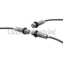
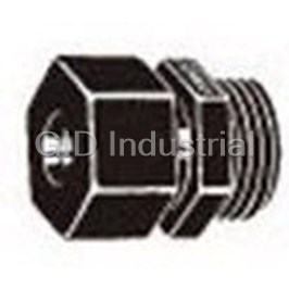
Ultrasonic 18 Mm Cylindrical
E99C
Part Number
E99C
Price
Request Quote
Manufacturer
OMRON AUTOMATION
Lead Time
Request Quote
Category
Connectors » Connector Other
Specifications
Manufacturer
Omron Automation
Manufacturers Part #
E99C
Lead Time
8 Week Lead Time
Industry Aliases
E99-C
Sub-Category
Other Connectors
Factory Pack Quantity
1
Datasheet

Extracted Text
Ultrasonic Proximity Sensor E4C Compact, Cylindrical Ultrasonic Proximity Sensor with Separate Amplifier Unit ■ Stable operation for a variety of objects regardless of color, transparency, or material (metallic or non- metallic). ■ Compact M18-sized cylindrical head. ■ Prevent mutual interference using a synchroniza- tion selector. ■ With reflective models, setting sensing zones ensures detection without influence by the back- ground. Ordering Information Sensors (Refer to Dimensions on page 7.) Amplifier Units (Refer to Dimensions on page 7.) Sensing method Sensing distance Model Supply voltage Model Through-beam E4C-TS50 12 to 24 VDC E4C-WH4T 50 cm Reflective E4C-LS35 12 to 24 VDC E4C-WH4L 10 to 35 cm (convergent reflective) Application Examples Detection of transparent bottles and containers Detection of milk packages 1 E4C E4C Specifications ■ Ratings/Characteristics Sensors Model E4C-TS50 E4C-LS35 Item Sensing method Through-beam Reflective Sensing distance 50 cm 10 to 35 cm (possible to limit the sensing zone within a range between 2 and 25 cm) Standard sensing object 10 x 10 cm flat plate 4 x 4 cm flat plate Ultrasonic oscillation frequency Approx. 270 kHz Response frequency 50 Hz 20 Hz Directional angle (see note 1) ±8° max. Indicator SENSING indicator (red LED) Ambient temperature Operating: –10°C to 55°C (with no icing) Ambient humidity Operating: 35 to 95% Vibration resistance Destruction: 10 to 55 Hz, 1.5-mm double amplitude for 2 hours each in X, Y, and Z directions 2 Shock resistance (approx. 50G) 3 times each in X, Y, and Z directions Destruction: 500 m/s Degree of protection (see note 2) IEC IP66 Cord length 2 m Weight Approx. 300 g (with Emitter and Receiver) Approx. 150 g Material Case Heat-resistant ABS resin Oscillator Ceramic Nut Polyacetal resin Note: 1. This is the half-value angle obtainable with a signal of -6 dB. 2. The enclosure rating indicates the degree of protection of the case, which will depend on the operating condition. Amplifier Units Model E4C-WH4T E4C-WH4L Item Sensing method Through-beam Reflective Sensing distance 50 cm 10 to 35 cm Supply voltage 12 to 24 VDC ±10% with a max. ripple ±10% (p-p) (operating voltage range) Current consumption 100 mA max. at 12 VDC Differential travel --- 20% max. of rated sensing distance Response frequency (see note) 50 Hz 20 Hz Control output Terminal output: 100 mA max. (NPN or PNP open collector output at 40 VDC with a residual voltage (residual voltage) of 2 V) Connector output: 50 mA max. (photocoupler output) Operation mode Normally open or normally closed (selectable with a slide switch) Ultrasonic compensation Yes Indicator SENSING indicator (red LED) and STABILITY indicator (green LED) Ambient temperature Operating: –10°C to 55°C (with no icing) Ambient humidity Operating: 35 to 95% Temperature influence ±30% max. of sensing distance at 20°C in the ±10% max. of sensing distance at 20°C in the temperature range of –10°C and 55°C temperature range of –10°C and 55°C Voltage influence ±10% max. of sensing distance at a voltage between 90% and 110% of the rated power supply voltage Insulation resistance 20 MΩ min. (at 500 VDC) between current carry parts and case Dielectric strength 1,000 VAC (50/60 Hz) for 1 min between current carry parts and case Vibration resistance Destruction: 10 to 55 Hz, 1.5-mm double amplitude for 2 hours each in X, Y, and Z directions 2 Shock resistance Destruction: 500 m/s (approx. 50G) 3 times each in X, Y, and Z directions Degree of protection IEC IP40 Weight Approx. 110 g Materials Case: ABS Note: The response frequencies are values obtained with the E4C used for detecting the rotating propeller-shaped disc as shown on the right. 2 E4C E4C Space:blade = 1:1 Engineering Data Sensing Range (Typical) Parallel Movement Operating Distance vs. Characteristics (Typical) Sensing Object Size (Typical) E4C-LS35 E4C-TS50 E4C-LS35 Standard sensing object (4 x 4 cm flat plate) Power supply voltage: 12 VDC Sensing adjuster: 10 Sensitivity Adjuster: Max. Zone adjuster: 25 Operating range Operating range Operating range Sensing object: Column Obtain the point that turns Y and Y ON 1 2 Dia.: d (cm) while changing the sensing distance (X). Sensing distance X (cm) Setting distance X (cm) Setting distance X (cm) Ambient Temperature vs. Operating Distance vs. Variation Rate of Sensing Sensing Object Angle (Typical) Distance (Typical) E4C-TS50 E4C-LS35 E4C-TS50+ E4C-WH4T Sensor and Amplifier: Same temperature Distance adjuster: 10 variation Zone adjuster: 25 Sensitivity adjuster: Max. θ° Operating range Operating range Sensitivity adjuster: Max. Receiver Emitter Sensing object (dia. d mm) Operating distance X (cm) Ambient temperature (°C) Object passing position X (cm) E4C-TS50+E4C-WH4T E4C-TS50+E4C-WH4T E4C-LS35+E4C-WH4L Sensor: Constant room temperature Sensor and Amplifier: Same temperature Sensor: Temperature varied variation Amplifier: Temperature varied Amplifier: Constant room temperature Sensitivity adjuster: Max. Distance adjuster: 10 Sensitivity adjuster: Max. Zone adjuster: 25 Ambient temperature (°C) Ambient temperature (°C) Ambient temperature (°C) 3 Variation rate of sensing distance (%) Sensing range Y (cm) Sensing object dia. d (cm) Variation rate of sensing distance (%) Angle (°) Operating distance Y (cm) Variation rate of sensing distance (%) Variation rate of sensing distance (%) Sensing object dia. d (cm) E4C E4C Sensitivity Adjuster Position vs. Parallel Movement Characteristics E4C-LS35+E4C-WH4L E4C-LS35+E4C-WH4L E4C-TS50+E4C-WH-4T Obtain the point that turns Y and Y ON 1 2 Sensor: Temperature varied Sensor: Constant room temperature while changing the sensing distance (X). Amplifier: Constant room temperature Amplifier: Temperature varied Distance adjuster: 10 Distance adjuster: 10 Zone adjuster: 25 Zone adjuster: 25 Sensitivity adjuster: Center Sensitivity adjuster: Max. Setting distance X (cm) Ambient temperature (°C) Ambient temperature (°C) ■ Amplifier Units Indicators Asynchronous/Synchronous (MON/SYN) Switch STABILITY Indicator (Green)If more than one Sensor is us ed in one place, the Sensors need to be in synchronous operation for the prevention of mutual inter- When this indicator is lit, the ultrasonic input into the Receiver is ference. A maximum of four Sensors can be in synchronous op- sufficient, or its interruption small enough, to ensure the smooth eration. operation of the E4C. Do not operate the E4C when this indicator is not lit.Connect the DC power supply and Sensor to each Amplifier as usual. SENSING Indicator (Red) Use the E99-C (order separatel y) connector to connect the Sen- When this indicator is lit, the Receiver has ultrasonic input. sor to the Amplifier. Operation Selector (H1/H2)If the case of the connections shown in the following illustration, set the selector of only one Amplifier (No. 1 in the following case) Incident-ON (H1) to MON. Set the selector of any other Amplifier to SYN. Light incident E99-C Connector Light interrupted (order separately) (see note) (see note) (see note) ON SENSING indicator (red) OFF Output transistor ON (Both PNP and NPN outputs) OFF Operate Load (e.g., relay) Release Incident-OFF (H2) Light incident Light interrupted Sensors ON Amplifiers SENSING indicator (red) OFF Output transistor Note: The E99-C Connector will be most effective if the E4C is ON (Both PNP and NPN outputs) a reflective model although the E99-C Connector is re- OFF quired by both the reflective and through-beam models. Operate When using through-beam models, however, be sure to Load (e.g., relay) Release maintain enough between adjacent Sensors to suppress mutual interference. Refer to Sensitivity Adjuster Position vs. Parallel Movement Characteristics in Engineering Da- Note: The load in operation is connected to the output circuit of ta. the E4C. 4 Variation rate of sensing distance (%) Variation rate of sensing distance (%) Operating distance Y (cm) E4C E4C ■ Sensitivity/Zone Adjustments Pass the sensing object through the sensing range and adjust the E4C-TS50 and E4C-WH4T Through-beam Models sensitivity so that the SENSING indicator turns ON and OFF Set the SENSITIVITY adjuster of the Receiver to maximum. according the presence or absence of the sensing object while Move the Emitter and Receiver vertically and horizontally until the the STABILITY indicator is lit continuously. SENSING indicator of the Receiver is lit and secure the Emitter If the STABILITY indicator is not lit while the Sensor is in opera- and Receiver at the midpoint of the range within which the STA- tion, this may indicate a possible operational error. Check or read- BILITY indicator is lit. just the sensitivity. If the Emitter and Receiver are set at a distance shorter than the Range in which the STABILITY indicator (green) lit rated sensing distance, reduce the sensitivity to within the range in which the STABILITY indicator is lit. This will increase the immunity of the Sensor against noise. Optimum line Range in which the SENSING indicator (red) lit E4C-LS35 and E4C-WH4L Convergent Reflective Model Locate the Sensor so that both the STABILITY and SENSING indicators will be lit when the sensing object is placed at the sensing posi- tion, and the STABILITY indicator will be lit and the SENSING indicator will turn OFF when the sensing object is removed. Step 1 2 3 4 Sensing 35 cm Distance adjuster --- --- Zone adjuster Adjustment Place the sensing object at Move the Emitter and Re- Remove the sensing object The sensing zone can be procedure the sensing position and ceiver vertically and hori- and check that the SENS- set within a range of 2 to 25 turn the distance adjuster zontally and secure the ING indicator is OFF and cm with the zone adjuster. clockwise gradually until Emitter and Receiver at the the STABILITY indicator is both the SENSING and midpoint of the range within continuously lit. STABILITY indicators are which the STABILITY indi- lit. (See note 2) cator is lit. Note: 1. If the STABILITY indicator is not lit while the Sensor is in operation, this indicates a possible operational error. Check or readjust the sensitivity. 2. The sensing distance is adjustable within a range of 10 to 35 cm with the distance adjuster. 3. Adjust the sensing zone within the sensing distance adjustable range (i.e., 10 to 35 cm). 5 Sensing object Background Sensing object Background Sensing object Background Sensing object Background E4C E4C Sensing Zone Setting Example Relationship between Incident-ON and Incident- OFF Sensing zone Example: Sensing distance set to 15 cm and zone set to 10 cm Sensing distance Sensing zone adjustment adjustment Incident-ON Sensing distance Sensing zone adjustment adjustment Incident-OFF Note: Make the settings as shown above to set a sensing zone of 10 cm with a sensing distance adjustment of 15 cm. Stable sensing zone Unstable Non-sensing (adjustable) sensing zone zone (Outside the ratings) (Outside the ratings) Note: Set the zone within a distance of 10 to 35 cm from the Sensor. Therefore, if the distance adjuster is set to 30 cm and zone adjuster is set to 20 cm, the sensing zone will be 5 cm from a point 30 cm away from the Sensor. Step 1 2 Distance adjuster and zone adjuster Adjustment Set the distance ad- Set the zone adjuster procedure juster to 15 cm to 10 cm. Nomenclature E4C-WH4T E4C-WH4L Asynchronous/Syn- Asynchronous/Syn- chronous (MON/SYN) chronous (MON/SYN) operation selector operation selector Operation (H1/H2) selector Operation (H1/H2) selector Zone adjuster SENSING indicator SENSING indicator Sensitivity adjuster Distance (sensing STABILITY indicator STABILITY indicator distance) adjuster Operation ■ Output Circuit 12 to 24 V Load PNP output E4C 100 mA max. main Load circuit NPN output 100 mA max. 0 V 6 Background object E4C E4C Dimensions Note: All units are in millimeters unless otherwise indicated. Sensors E4C-TS50 E4C-LS35 Mounting Holes SENSITIVITY indicator 18.5 dia. 11 dia. 8 dia. 9 dia. (See note) Note: E4C-TS50R or E4C-LS35: 3-conductor, shielded cord (6 dia., UL2791) with 7/0.25 dia. (standard length: 2 m) E4C-TS50S: 2-conductor, shielded cord (6 dia., UL20276) with 7/0.25 dia. (standard length: 2 m) Amplifier Units E4C-WH4T Eight, M3.5 terminal screws Two, M4 screw mounting holes Mounting Holes Two, 4.5 dia. (See note) Note: DIN track mounting side Eight, M3.5 terminal screws E4C-WH4L Two, M4 screw mounting holes Mounting Holes Two, 4.5 dia. (See note) Note: DIN track mounting side 7 E4C E4C Installation ■ Connections E4C-WH4T E4C-WH4L 12 to 24 VDC 12 to 24 VDC Output 2 (PNP) Output 1 (NPN) Output 1 (NPN) Output 2 (PNP) 100 mA max., 100 mA max., 100 mA max., 100 mA max., 40 VDC max. 40 VDC max. 40 VDC max. 40 VDC max. Black Red Black Red White White Shield Shield E4C-LS35 E4C-TS50 Precautions ■ Correct Use Sensor Mounting Angle Environmental Conditions If the E4C is in level control or distance control of sensing objects, Do not use the E4C at a temperature exceeding the rated range the stability of signal detection will depend on the sensing surface or outdoors, otherwise the reliability and life of the E4C will condition of the objects. Considering the repose angle of the decrease. objects, mount the E4C so that the ultrasonic beam and the sens- The Ultrasonic Reflective Sensor utilizes the air as a beam trans- ing surface of each object meet at right angles to each other. mission media. Do not use the E4C in places with radical convec- tion or extreme local temperature changes. For example, if there Surrounding Objects is a hot air curtain that causes turbulence within the sensing area, Make sure that the Sensor is free from surrounding objects that the E4C may malfunction. reflect the ultrasonic beam diffusion, otherwise the Sensor may malfunction. In particular, pay the utmost attention so that no side lobe of the ultrasonic beam will be reflected by such objects. Turbulence Air curtain Mounting Securely mount the E4C by using the nuts provided with the E4C or the mounting holes of the E4C. Refer to Dimensions for details. Emitter Do not strike the Sensor with any hammer or other object, other- wise the E4C will no longer be water-resistant. If the E4C is not mounted securely, the E4C may be damaged by vibration or may not detect sensing objects accurately due to a possible change in the mounting position. Receiver The jetting sound of air nozzles includes noise of a wide fre- quency range, which will affect the operation of the E4C. Do not use an air nozzle near the E4C. The sensing distance of the E4C will decrease if there is any water drops on the surface of the emitter or receiver. The reflective model may not detect any objects if there is any object absorbing sound, such as powder and cotton, on the sur- face of the emitter or receiver. 8 E4C E4C Mutual Interference If more than one Unit is closely mounted together or used in a narrow space, the mutual interference of the Sensors will result. To prevent this, set the MON/SYN selector to SYN and check that no mutual interference results. Connections The cord length between the Sensor and Amplifier can be a max- imum of 20 m provided that the cord is a three-conductor, shielded cord (6 dia., UL2791) with 7/0.25 dia. If the Emitter is the E4C-TS50S, however, use a two-conductor, non-shielded cord (6 dia. UL20276) with 7/0.25 dia. Do not wire the lines of the E4C along with high-tension or power lines in the same conduit or close together, otherwise the E4C may malfunction due to inductive noise. The power supply lines of the Amplifier can be extended up to 100 m provided that the size of the cord is 0.3 dia. or more. Others Be sure not to turn the sensitivity adjuster excessively. If the sen- sitivity adjuster is turned exceeding the permissible range, no sensitivity adjustment will be possible again. Take the measures shown in the following illustrations if multiple reflection results. 5-dia. slit Wall Wall Urethane rubber or sponge The sensing distance will be, however, reduced to half (i.e., 10 to 17 cm) if the slit is used. If the sensing zone is set to a small value (i.e., a few centimeters) on the E4C reflective model, the E4C may require a warming-up time of 3 minutes or more after the E4C is turned ON. ALL DIMENSIONS SHOWN ARE IN MILLIMETERS. To convert millimeters into inches, multiply by 0.03937. To convert grams into ounces, multiply by 0.03527. In the interest of product improvement, specifications are subject to change without notice. 9 Terms and Conditions of Sale 1. Offer; Acceptance. These terms and conditions (these "Terms") are deemed ITY OR FITNESS FOR A PARTICULAR PURPOSE OF THE PRODUCTS. part of all quotes, agreements, purchase orders, acknowledgments, price lists, BUYER ACKNOWLEDGES THAT IT ALONE HAS DETERMINED THAT THE catalogs, manuals, brochures and other documents, whether electronic or in PRODUCTS WILL SUITABLY MEET THE REQUIREMENTS OF THEIR writing, relating to the sale of products or services (collectively, the "Products") INTENDED USE. Omron further disclaims all warranties and responsibility of by Omron Electronics LLC and its subsidiary companies (“Omron”). Omron any type for claims or expenses based on infringement by the Products or oth- objects to any terms or conditions proposed in Buyer’s purchase order or other erwise of any intellectual property right. (c) Buyer Remedy. Omron’s sole obli- documents which are inconsistent with, or in addition to, these Terms. gation hereunder shall be, at Omron’s election, to (i) replace (in the form 2. Prices; Payment Terms. All prices stated are current, subject to change with- originally shipped with Buyer responsible for labor charges for removal or out notice by Omron. Omron reserves the right to increase or decrease prices replacement thereof) the non-complying Product, (ii) repair the non-complying on any unshipped portions of outstanding orders. Payments for Products are Product, or (iii) repay or credit Buyer an amount equal to the purchase price of due net 30 days unless otherwise stated in the invoice. the non-complying Product; provided that in no event shall Omron be responsi- 3. Discounts. Cash discounts, if any, will apply only on the net amount of invoices ble for warranty, repair, indemnity or any other claims or expenses regarding sent to Buyer after deducting transportation charges, taxes and duties, and will the Products unless Omron’s analysis confirms that the Products were prop- be allowed only if (i) the invoice is paid according to Omron’s payment terms erly handled, stored, installed and maintained and not subject to contamina- and (ii) Buyer has no past due amounts. tion, abuse, misuse or inappropriate modification. Return of any Products by 4. Interest. Omron, at its option, may charge Buyer 1-1/2% interest per month or Buyer must be approved in writing by Omron before shipment. Omron Compa- the maximum legal rate, whichever is less, on any balance not paid within the nies shall not be liable for the suitability or unsuitability or the results from the stated terms. use of Products in combination with any electrical or electronic components, 5. Orders. Omron will accept no order less than $200 net billing. circuits, system assemblies or any other materials or substances or environ- 6. Governmental Approvals. Buyer shall be responsible for, and shall bear all ments. Any advice, recommendations or information given orally or in writing, costs involved in, obtaining any government approvals required for the impor- are not to be construed as an amendment or addition to the above warranty. tation or sale of the Products. See http://www.omron247.com or contact your Omron representative for pub- 7. Taxes. All taxes, duties and other governmental charges (other than general lished information. real property and income taxes), including any interest or penalties thereon, 14. Limitation on Liability; Etc. OMRON COMPANIES SHALL NOT BE LIABLE imposed directly or indirectly on Omron or required to be collected directly or FOR SPECIAL, INDIRECT, INCIDENTAL, OR CONSEQUENTIAL DAMAGES, indirectly by Omron for the manufacture, production, sale, delivery, importa- LOSS OF PROFITS OR PRODUCTION OR COMMERCIAL LOSS IN ANY tion, consumption or use of the Products sold hereunder (including customs WAY CONNECTED WITH THE PRODUCTS, WHETHER SUCH CLAIM IS duties and sales, excise, use, turnover and license taxes) shall be charged to BASED IN CONTRACT, WARRANTY, NEGLIGENCE OR STRICT LIABILITY. and remitted by Buyer to Omron. Further, in no event shall liability of Omron Companies exceed the individual 8. Financial. If the financial position of Buyer at any time becomes unsatisfactory price of the Product on which liability is asserted. to Omron, Omron reserves the right to stop shipments or require satisfactory 15. Indemnities. Buyer shall indemnify and hold harmless Omron Companies and security or payment in advance. If Buyer fails to make payment or otherwise their employees from and against all liabilities, losses, claims, costs and comply with these Terms or any related agreement, Omron may (without liabil- expenses (including attorney's fees and expenses) related to any claim, inves- ity and in addition to other remedies) cancel any unshipped portion of Prod- tigation, litigation or proceeding (whether or not Omron is a party) which arises ucts sold hereunder and stop any Products in transit until Buyer pays all or is alleged to arise from Buyer's acts or omissions under these Terms or in amounts, including amounts payable hereunder, whether or not then due, any way with respect to the Products. Without limiting the foregoing, Buyer (at which are owing to it by Buyer. Buyer shall in any event remain liable for all its own expense) shall indemnify and hold harmless Omron and defend or set- unpaid accounts. tle any action brought against such Companies to the extent based on a claim 9. Cancellation; Etc. Orders are not subject to rescheduling or cancellation that any Product made to Buyer specifications infringed intellectual property unless Buyer indemnifies Omron against all related costs or expenses. rights of another party. 10. Force Majeure. Omron shall not be liable for any delay or failure in delivery 16. Property; Confidentiality. Any intellectual property in the Products is the exclu- resulting from causes beyond its control, including earthquakes, fires, floods, sive property of Omron Companies and Buyer shall not attempt to duplicate it strikes or other labor disputes, shortage of labor or materials, accidents to in any way without the written permission of Omron. Notwithstanding any machinery, acts of sabotage, riots, delay in or lack of transportation or the charges to Buyer for engineering or tooling, all engineering and tooling shall requirements of any government authority. remain the exclusive property of Omron. All information and materials supplied 11. Shipping; Delivery. Unless otherwise expressly agreed in writing by Omron: by Omron to Buyer relating to the Products are confidential and proprietary, a. Shipments shall be by a carrier selected by Omron; Omron will not drop ship and Buyer shall limit distribution thereof to its trusted employees and strictly except in “break down” situations. prevent disclosure to any third party. b. Such carrier shall act as the agent of Buyer and delivery to such carrier shall 17. Export Controls. Buyer shall comply with all applicable laws, regulations and constitute delivery to Buyer; licenses regarding (i) export of products or information; (iii) sale of products to c. All sales and shipments of Products shall be FOB shipping point (unless oth- “forbidden” or other proscribed persons; and (ii) disclosure to non-citizens of erwise stated in writing by Omron), at which point title and risk of loss shall regulated technology or information. pass from Omron to Buyer; provided that Omron shall retain a security inter- 18. Miscellaneous. (a) Waiver. No failure or delay by Omron in exercising any right est in the Products until the full purchase price is paid; and no course of dealing between Buyer and Omron shall operate as a waiver d. Delivery and shipping dates are estimates only; and of rights by Omron. (b) Assignment. Buyer may not assign its rights hereunder e.Omron will package Products as it deems proper for protection against nor- without Omron's written consent. (c) Law. These Terms are governed by the law of the jurisdiction of the home office of the Omron company from which mal handling and extra charges apply to special conditions. 12. Claims. Any claim by Buyer against Omron for shortage or damage to the Buyer is purchasing the Products (without regard to conflict of law princi- Products occurring before delivery to the carrier must be presented in writing ples). (d) Amendment. These Terms constitute the entire agreement between to Omron within 30 days of receipt of shipment and include the original trans- Buyer and Omron relating to the Products, and no provision may be changed portation bill signed by the carrier noting that the carrier received the Products or waived unless in writing signed by the parties. (e) Severability. If any provi- from Omron in the condition claimed. sion hereof is rendered ineffective or invalid, such provision shall not invalidate 13. Warranties. (a) Exclusive Warranty. Omron’s exclusive warranty is that the any other provision. (f) Setoff. Buyer shall have no right to set off any amounts Products will be free from defects in materials and workmanship for a period of against the amount owing in respect of this invoice. (g) Definitions. As used twelve months from the date of sale by Omron (or such other period expressed herein, “including” means “including without limitation”; and “Omron Compa- in writing by Omron). Omron disclaims all other warranties, express or implied. nies” (or similar words) mean Omron Corporation and any direct or indirect (b) Limitations. OMRON MAKES NO WARRANTY OR REPRESENTATION, subsidiary or affiliate thereof. EXPRESS OR IMPLIED, ABOUT NON-INFRINGEMENT, MERCHANTABIL- Certain Precautions on Specifications and Use 1. Suitability of Use. Omron Companies shall not be responsible for conformity ADDRESS THE RISKS, AND THAT THE OMRON’S PRODUCT IS PROP- with any standards, codes or regulations which apply to the combination of the ERLY RATED AND INSTALLED FOR THE INTENDED USE WITHIN THE Product in the Buyer’s application or use of the Product. At Buyer’s request, OVERALL EQUIPMENT OR SYSTEM. Omron will provide applicable third party certification documents identifying 2. Programmable Products. Omron Companies shall not be responsible for the ratings and limitations of use which apply to the Product. This information by user’s programming of a programmable Product, or any consequence thereof. itself is not sufficient for a complete determination of the suitability of the Prod- 3. Performance Data. Data presented in Omron Company websites, catalogs uct in combination with the end product, machine, system, or other application and other materials is provided as a guide for the user in determining suitabil- or use. Buyer shall be solely responsible for determining appropriateness of ity and does not constitute a warranty. It may represent the result of Omron’s the particular Product with respect to Buyer’s application, product or system. test conditions, and the user must correlate it to actual application require- Buyer shall take application responsibility in all cases but the following is a ments. Actual performance is subject to the Omron’s Warranty and Limitations non-exhaustive list of applications for which particular attention must be given: of Liability. (i) Outdoor use, uses involving potential chemical contamination or electrical 4. Change in Specifications. Product specifications and accessories may be interference, or conditions or uses not described in this document. changed at any time based on improvements and other reasons. It is our prac- (ii) Use in consumer products or any use in significant quantities. tice to change part numbers when published ratings or features are changed, (iii) Energy control systems, combustion systems, railroad systems, aviation or when significant construction changes are made. However, some specifica- systems, medical equipment, amusement machines, vehicles, safety equip- tions of the Product may be changed without any notice. When in doubt, spe- ment, and installations subject to separate industry or government regulations. cial part numbers may be assigned to fix or establish key specifications for (iv) Systems, machines and equipment that could present a risk to life or prop- your application. Please consult with your Omron’s representative at any time erty. Please know and observe all prohibitions of use applicable to this Prod- to confirm actual specifications of purchased Product. uct. 5. Errors and Omissions. Information presented by Omron Companies has been NEVER USE THE PRODUCT FOR AN APPLICATION INVOLVING SERIOUS checked and is believed to be accurate; however, no responsibility is assumed RISK TO LIFE OR PROPERTY OR IN LARGE QUANTITIES WITHOUT for clerical, typographical or proofreading errors or omissions. ENSURING THAT THE SYSTEM AS A WHOLE HAS BEEN DESIGNED TO OMRON ELECTRONICS LLC • THE AMERICAS HEADQUARTERS • Schaumburg, IL USA • 847.843.7900 • 800.556.6766 • www.omron247.com OMRON CANADA, INC. • HEAD OFFICE OMRON ARGENTINA • SALES OFFICE Toronto, ON, Canada • 416.286.6465 • 866.986.6766 Cono Sur • 54.11.4783.5300 www.omron247.com OMRON ELETRÔNICA DO BRASIL LTDA • HEAD OFFICE OMRON CHILE • SALES OFFICE São Paulo, SP, Brasil • 55.11.2101.6300 • www.omron.com.br Santiago • 56.9.9917.3920 OMRON ELECTRONICS MEXICO SA DE CV • HEAD OFFICE OTHER OMRON LATIN AMERICA SALES Apodaca, N.L. • 52.811.156.99.10 • 001.800.556.6766 • mela@omron.com 54.11.4783.5300 OMRON EUROpE B.V. Wegalaan 67-69, NL-2132 JD, Hoofddorp, The Netherlands. Tel: +31 (0) 23 568 13 00 Fax: +31 (0) 23 568 13 88 www.industrial.omron.eu Cat. D072-E1-03 10/10 Note: Specifications are subject to change. © 2010 Omron Electronics LLC
Frequently asked questions
How does Electronics Finder differ from its competitors?

Is there a warranty for the E99C?
Which carrier will Electronics Finder use to ship my parts?
Can I buy parts from Electronics Finder if I am outside the USA?
Which payment methods does Electronics Finder accept?
Why buy from GID?

Quality
We are industry veterans who take pride in our work

Protection
Avoid the dangers of risky trading in the gray market

Access
Our network of suppliers is ready and at your disposal

Savings
Maintain legacy systems to prevent costly downtime

Speed
Time is of the essence, and we are respectful of yours
Related Products
Connector Other SC6
Ejector Header/Terminal Block 50/50 POS ST XW2D-50Y6
Request a Quote

The quote request has been received
Close

Facing challenges or have inquiries? Feel free to contact us!
Call Us +1-469-283-2440
What they say about us
FANTASTIC RESOURCE
One of our top priorities is maintaining our business with precision, and we are constantly looking for affiliates that can help us achieve our goal. With the aid of GID Industrial, our obsolete product management has never been more efficient. They have been a great resource to our company, and have quickly become a go-to supplier on our list!
Bucher Emhart Glass
EXCELLENT SERVICE
With our strict fundamentals and high expectations, we were surprised when we came across GID Industrial and their competitive pricing. When we approached them with our issue, they were incredibly confident in being able to provide us with a seamless solution at the best price for us. GID Industrial quickly understood our needs and provided us with excellent service, as well as fully tested product to ensure what we received would be the right fit for our company.
Fuji
HARD TO FIND A BETTER PROVIDER
Our company provides services to aid in the manufacture of technological products, such as semiconductors and flat panel displays, and often searching for distributors of obsolete product we require can waste time and money. Finding GID Industrial proved to be a great asset to our company, with cost effective solutions and superior knowledge on all of their materials, it’d be hard to find a better provider of obsolete or hard to find products.
Applied Materials
CONSISTENTLY DELIVERS QUALITY SOLUTIONS
Over the years, the equipment used in our company becomes discontinued, but they’re still of great use to us and our customers. Once these products are no longer available through the manufacturer, finding a reliable, quick supplier is a necessity, and luckily for us, GID Industrial has provided the most trustworthy, quality solutions to our obsolete component needs.
Nidec Vamco
TERRIFIC RESOURCE
This company has been a terrific help to us (I work for Trican Well Service) in sourcing the Micron Ram Memory we needed for our Siemens computers. Great service! And great pricing! I know when the product is shipping and when it will arrive, all the way through the ordering process.
Trican Well Service
GO TO SOURCE
When I can't find an obsolete part, I first call GID and they'll come up with my parts every time. Great customer service and follow up as well. Scott emails me from time to time to touch base and see if we're having trouble finding something.....which is often with our 25 yr old equipment.
ConAgra Foods