

 Manufacturers
OMRON AUTOMATION EE-SPZ401-1

Description
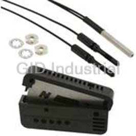
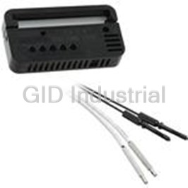
Photomicrosensor With Built-In Amplifier (With Light Modulation)
EE-SPZ401-1
Part Number
EE-SPZ401-1
Price
Request Quote
Manufacturer
OMRON AUTOMATION
Lead Time
Request Quote
Category
Sensors and Transducers » Photoelectric Sensor
Specifications
Manufacturer
Omron Automation
Manufacturers Part #
EE-SPZ401-1
Industry Aliases
EE-SPZ401-1
Sub-Category
Photoelectric Sensors
Factory Pack Quantity
1
Datasheet

Extracted Text
Photomicrosensor with Built-in Amplifier (with Light Modulation) EE-SPZ301/401 CSM_EE-SPZ301_401_DS_E_2_1 Use standard optical fiber. • Photomicrosensor with light modulation for reduced external light interference. Easy adjustment and operation validation with an operation indicator (lights when light is incident). Wide operating voltage range: 5 to 24 VDC Supports connection with Programmable Controllers (PLCs). Easy-to-wire connectors assure easy maintenance. Be sure to read Safety Precautions on page 5. Ordering Information Infrared light Appearance Application Output configuration Model Dark-ON EE-SPZ301 Fiber connection Light-ON EE-SPZ401 Fiber Unit and Attachment Combinations Directional Model Fiber Unit Attachment Sensing distance Sensing object angle --- Opaque: 1 mm dia. 20 mm 5 to 40° (Lens) (Through-beam) Opaque: 4 mm dia. min. 150 mm (Fiber connection) E39-F1 E32-TC200 EE-SPZ301 (Side-view) EE-SPZ401 Opaque: 3 mm dia. min. 20 to 60° 10 mm E39-F2 (Reflective) --- White paper: 15×15 mm --- 1 to 6 mm E32-DC200 Note 1. The sensing distance given is a reference value applicable only when the fiber length is 60 cm. (Refer to the engineering data for the relationship between fiber length and sensing distance.) 2. Ambient operating temperature of Fiber section: −40 to 70°C, Attachment: −40 to 200°C, Retroreflector: −40 to 70°C 3. Ambient humidity: 5% to 85% 1 EE-SPZ301/401 Ratings and Specifications Item Models EE-SPZ301, EE-SPZ401 Power supply voltage 5 to 24 VDC ±10%, ripple (p-p): 5% max. Current consumption Average: 15 mA max., Peak: 50 mA max. Response frequency 100 Hz 5 to 24 VDC Control output 80 mA load current with a residual voltage of 1.0 V max. 10 mA load current with a residual voltage of 0.4 V max. Light source GaAs infrared LED (pulse lighting) with a peak wavelength of 940 nm Indicator Light indicator (red) Light-receiving element Si photodiode (Maximum sensitivity wavelength: 850 mm) Ambient illumination 3,000 lx max. with incandescent light or sunlight on the surface of the receiver Degree of protection IEC Standard IP50 (excluding terminal section.) Operating: −10 to +55°C Ambient temperature Storage: −25 to +65°C Operating: 5% to 85% Ambient humidity Storage: 5% to 95% Permissible bending 25 mm radius of Fiber Unit Through-beam: 180 cm Maximum fiber length Reflective: 100 cm Vibration resistance Destruction: 10 to 55 Hz, 1.5-mm double amplitude for 2 h each in X, Y, and Z directions 2 Shock resistance Destruction: 500 m/s for 3 times each in X, Y, and Z directions Cable 2 m max. (Thickness: AWG24 min.) Weight Approx. 3.0 g 2 EE-SPZ301/401 Engineering Data (Typical) Receiver Output vs. Sensing Distance Characteristics E32-TC200 E32-TC200 EE-SPZ301 EE-SPZ301 EE-SPZ301 + E32-TC200 + + } } } E39-F1 E39-F2 EE-SPZ401 EE-SPZ401 EE-SPZ401 50 1000 1000 Vo Vo Vo Measuring conditions Measuring conditions Measuring conditions (mV) (mV) (mV) 500 45 Vcc = 10 V 500 Vcc = 10 V Vcc = 10 V Fiber length: 60 cm Fiber length: 60 cm Fiber length: 60 cm 300 300 40 35 100 100 30 50 50 25 30 30 20 10 10 15 5 5 10 Operating level Operating level 3 3 5 Operating level 1 0 1 0 5 10 15 20 25 0 50 100 150 200 250 300 0 5 10 15 20 25 30 Distance d (mm) Distance d (mm) Distance d (mm) Sensing Angle Characteristics Receiver Output vs. Bending Radius EE-SPZ301 EE-SPZ301 EE-SPZ301Y-01 + E32-DC200 + E32-DC200 } } EE-SPZ401 EE-SPZ401 EE-SPZ401Y-01 120 50 10 Vo +θ −θ Measuring conditions 110 (mV) Vcc = 10 V 45 9 Through-beam d White paper 100 (reflection factor: 90%) 40 8 Measuring conditions d 90 Fiber length: 60 cm Vcc = 10 V 35 7 White paper 80 Reflective (reflection factor: 90%) 30 6 70 Fiber length: 60 cm 60 25 5 2 mm 50 20 4 40 15 3 White paper 30 (reflection factor: 90%) 10 2 20 Bending radius R 5 1 10 Operating level 0 0 0 5 10 15 20 25 30 35 40 2 4 6 8 10 12 −50 −40 −30 −20 −10 0 10 20 30 40 50 Angle θ (°) Distance d (mm) Bending radius R (mm) Sensing Position Characteristics E32-TC200 E32-TC200 EE-SPZ301 EE-SPZ301 EE-SPZ301 + E32-TC200 + + } } } E39-F1 E39-F2 EE-SPZ401 EE-SPZ401 EE-SPZ401 20 8 2.5 Measuring conditions Measuring conditions Measuring conditions Distance Y Vcc = 10 V 2 Vcc = 10 V Vcc = 10 V 15 6 Fiber length: 60 cm Fiber length: 60 cm Fiber length: 60 cm 1.5 Distance X 10 4 1 5 2 0.5 Distance Y 0 0 0 Distance X −0.5 −5 −2 −1 −10 −4 Parallel −1.5 move- ment −15 −6 dis- −2 tance Y Set distance X − −20 8 −2.5 0 50 100 150 200 250 300 0 5 10 15 20 25 30 0 2468 10 12 1416 Distance X (mm) Distance X (mm) Distance X (mm) 3 Distance Y (mm) Distance Y (mm) Distance d (mm) Distance Y (mm) Receiver output rate of change (%) EE-SPZ301/401 E32-TC200 EE-SPZ301 EE-SPZ301 + + E32-DC200 } } E39-F2 EE-SPZ401 EE-SPZ401 8 2 Measuring conditions Vcc = 10 V 6 1.5 Fiber length: 60 cm Distance Y 4 1 Distance X 2 0.5 0 0 Distance Z Y axis −2 −0.5 Distance X −4 −1 Measuring conditions Vcc = 10 V White paper (15 × 15 mm) −6 −1.5 (reflection factor: 90%) Fiber length: 60 cm −8 − 2 0 5 10 15 20 25 30 012345678 Distance X (mm) Distance X (mm) Fiber Length vs. Relative Sensing Distance Characteristics EE-SPZ301 EE-SPZ301 + E32-TC200 + E32-DC200 } } EE-SPZ401 EE-SPZ401 5 2 Relative sensing distance for Relative sensing distance for fiber length of 60 cm is set to 1. fiber length of 60 cm is set to 1. 1.8 4 1.6 1.4 3 1.2 1 2 0.8 0.6 1 0.4 0.2 0 0 20 40 60 80 100 120 140 20 40 60 80 100 120 140 160 180 200 220 Fiber length (cm) Fiber length (cm) I/O Circuit Diagrams Model Output configuration Timing charts Output circuit Incident Interrupted ON Light indicator (red) OFF ON Output EE-SPZ401 Light-ON transistor OFF + Light indicator 5 to 24 VDC Operates Load 1 (relay) Releases 1.5 to Load 1 H (relay) 3 mA Load 2 OUT Main L circuit Ic * Incident Load 2 Interrupted − 0 V ON Light indicator (red) OFF ON * Voltage output (when the sensor is connected to a transistor circuit) Output EE-SPZ301 Dark-ON transistor OFF Operates Load 1 (relay) Releases H Load 2 L 4 Distance Z (mm) Relative sensing distance Distance Y (mm) Relative sensing distance EE-SPZ301/401 Safety Precautions Refer to Warranty and Limitations of Liability. WARNING This product is not designed or rated for • Make sure that the terminals are not subjected to stress ensuring safety of persons. Do not use it for (external force). Stress will cause damage to the terminals. such purposes. Terminal Precautions for Correct Use • If a metal mounting base causes inductive noise, the Photomicrosensor falsely detect incident light. If necessary, Make sure that this product is used within the rated ambient implement the following countermeasures. environment conditions. (1) Connect the Sensor’s negative terminal and mounting Wiring frame so that they have the same electric potential. • A fiber that has been connected once cannot be (2) Connect the Sensor’s negative terminal and mounting disconnected. frame through a 0.47-µF capacitor. • Use a cable with a wire size of at least AWG22 (cross- (3) Insert a 10-mm-thick plastic insulation plate between the 2 sectional area: 0.3 mm ). The total cable length must be of Sensor and the mounting frame. 2 m maximum. • When driving a small inductive load, such as a relay, wire as • To use a cable length longer than 2 m, attach a capacitor shown below. (Be sure to connect a diode to absorb the with a capacitance of approximately 10 µF to the wires as reverse voltage.) shown below. The distance between the terminal and the capacitor must be within 2 m. (Use a capacitor with a dielectric strength that is at least twice the Sensor's power 5 to 24 VDC + D supply voltage.) OUT − X Relay 0 V 5 to 24 VDC + + A capacitor of 10 µF min. OUT − − 0 V Extension cable 2 m max. • The sensing distance of the EE-SPZ301/401 with the E32- DC200 are based on sensing a sheet of white paper with a reflection factor of 90%. • When using the EE-SPZ301/401 with the E32-DC200 to detect a piece of white paper with a reflection factor of 90%, the sensing distance varies from 6 to 10 mm depending on the product. • When using the EE-SPZ301/401 with the E32-DC200 to detect an object, the objects in the background should not be glossy. Decrease reflection from the background object, e.g., by providing a sufficient distance to the background or by using a black sponge or similar material as the background. • Connection is made using a connector. Do not solder to the pins (leads). Use EE-1002 a connector or a EE-1003 (with a 1-m cable) connector. A EE-1003A Hold-down clip is available to prevent the EE-1003 connector from becoming disconnected. 5 Sensing object Background object EE-SPZ301/401 Tightening the Fiber Unit Power Supply • For increased operation stability, install a FG (frame ground • Use a tightening force of 0.78 N·m max. terminal) or G (ground terminal) when using a commercially • Use a tool appropriate for the nut. available switching regulator + + OUT Mounting the Fiber Unit − G • Do not pull, press, or otherwise apply excessive force to the FG Fiber Unit. Switching regulator • The bending radius of the Fiber Unit must be as large as Mounting the Fiber Unit possible (radius: 25 mm min.). 1. Set at Fiber Unit at the specified length and cut it with the • As shown in the following figure, any bends must be made Fiber Cutting Tool. at least 40 mm from the base of the Unit. Do no Fiber Cutting Tool 20 mm min. • Insert the fiber into one of the insertion holes of the E39-F4 Cutting Tool to cut the fiber to the desired length. • Press down the blade of the Cutting Tool to cut the fiber in Amplifier unit Fiber unit a single stroke. Do not stop the Cutting Tool midway. • Each insertion hole can be used only once. Do not use it again, otherwise the fiber may 40 mm min. B not be cut properly and the sensing distance may decrease. A 2. Set the Fiber Unit in the EE-SPZ301/401. • Do not compress or apply a weight to the Fiber Unit. (Do not remove the Fiber Unit once it has been installed. Fiber unit Doing so may prevent the stopper in the Sensor from Nylon wire holder working properly, causing the Fiber Unit to become disconnected.) Installation • When three or four Through-beam Sensors must be installed side-by-side, place the emitters and receivers on alternating sides. • When using a Reflective Sensor to detect slow moving objects, incorrect operation may occur even if two Sensors are installed side-by-side. • Be sure to keep the Amplifier Unit under 55°C even when using the fiber ends in high temperature environments. • The connection force of the fiber and the Photomicrosensor will decrease when the ambient temperature is high. If high ambient temperatures can be expected, install the fiber with a holder or clip, and do not pull on the fiber. OUT Install the fiber with a holder or clip. 6 EE-SPZ301/401 (Unit: mm) Dimensions Unless otherwise specified, the tolerance class IT16 is used for dimensions in this data sheet. Sensors EE-SPZ301 EE-SPZ401 25 7.5 6 3 4.5 Two, 3.2 dia. holes Indicator window 3.1 3×3 1 1.25 2 5 14 20 26 2.5 3 @ 3- 0.635 Terminal Arrangement 3.4 dia. A Vcc B OUT OUTPUT 7.4 4.4 3 C GND (0 V) Fiber Units Standard Fiber, Through-beam Standard Fiber, Reflective E32-TC200 E32-DC200 Two hexagonal nuts Two hexagonal nuts Two toothed washers Two toothed washers Two, 1 dia. Optical fiber: Two, 2.2 dia. Sensing head: 1 dia. M2.6×0.45 4 dia. Sensing head: M4×0.7* Optical fiber: 2.2 dia. M6×0.75* 3.2 3 2.4 4.8 3 2.4 7 14 2,000 10 17 2,000 * Material: Brass/nickel plating * Material: ADC Other Products Lens Units Side-view Units E39-F1 E39-F2 M2.6 M2.6×0.45 Effective depth: 3.2 Effective depth: 3.8 Spot facing depth: 0.9 2.8 dia. Spot facing depth: 0.9 4 dia. 4 dia. 5.7 8.9 9.2 Note: Two per set. Note: Two per set. Fiber Cutter E39-F4 845 24.5 Standard-fiber insertion hole Thin-fiber insertion hole Note: Included with plastic fibers that allows free cutting. In the interest of product improvement, specifications are subject to change without notice. 7 Terms and Conditions of Sale 1. Offer; Acceptance. These terms and conditions (these "Terms") are deemed ITY OR FITNESS FOR A PARTICULAR PURPOSE OF THE PRODUCTS. part of all quotes, agreements, purchase orders, acknowledgments, price lists, BUYER ACKNOWLEDGES THAT IT ALONE HAS DETERMINED THAT THE catalogs, manuals, brochures and other documents, whether electronic or in PRODUCTS WILL SUITABLY MEET THE REQUIREMENTS OF THEIR writing, relating to the sale of products or services (collectively, the "Products") INTENDED USE. Omron further disclaims all warranties and responsibility of by Omron Electronics LLC and its subsidiary companies (“Omron”). Omron any type for claims or expenses based on infringement by the Products or oth- objects to any terms or conditions proposed in Buyer’s purchase order or other erwise of any intellectual property right. (c) Buyer Remedy. Omron’s sole obli- documents which are inconsistent with, or in addition to, these Terms. gation hereunder shall be, at Omron’s election, to (i) replace (in the form 2. Prices; Payment Terms. All prices stated are current, subject to change with- originally shipped with Buyer responsible for labor charges for removal or out notice by Omron. Omron reserves the right to increase or decrease prices replacement thereof) the non-complying Product, (ii) repair the non-complying on any unshipped portions of outstanding orders. Payments for Products are Product, or (iii) repay or credit Buyer an amount equal to the purchase price of due net 30 days unless otherwise stated in the invoice. the non-complying Product; provided that in no event shall Omron be responsi- 3. Discounts. Cash discounts, if any, will apply only on the net amount of invoices ble for warranty, repair, indemnity or any other claims or expenses regarding sent to Buyer after deducting transportation charges, taxes and duties, and will the Products unless Omron’s analysis confirms that the Products were prop- be allowed only if (i) the invoice is paid according to Omron’s payment terms erly handled, stored, installed and maintained and not subject to contamina- and (ii) Buyer has no past due amounts. tion, abuse, misuse or inappropriate modification. Return of any Products by 4. Interest. Omron, at its option, may charge Buyer 1-1/2% interest per month or Buyer must be approved in writing by Omron before shipment. Omron Compa- the maximum legal rate, whichever is less, on any balance not paid within the nies shall not be liable for the suitability or unsuitability or the results from the stated terms. use of Products in combination with any electrical or electronic components, 5. Orders. Omron will accept no order less than $200 net billing. circuits, system assemblies or any other materials or substances or environ- 6. Governmental Approvals. Buyer shall be responsible for, and shall bear all ments. Any advice, recommendations or information given orally or in writing, costs involved in, obtaining any government approvals required for the impor- are not to be construed as an amendment or addition to the above warranty. tation or sale of the Products. See http://www.omron247.com or contact your Omron representative for pub- 7. Taxes. All taxes, duties and other governmental charges (other than general lished information. real property and income taxes), including any interest or penalties thereon, 14. Limitation on Liability; Etc. OMRON COMPANIES SHALL NOT BE LIABLE imposed directly or indirectly on Omron or required to be collected directly or FOR SPECIAL, INDIRECT, INCIDENTAL, OR CONSEQUENTIAL DAMAGES, indirectly by Omron for the manufacture, production, sale, delivery, importa- LOSS OF PROFITS OR PRODUCTION OR COMMERCIAL LOSS IN ANY tion, consumption or use of the Products sold hereunder (including customs WAY CONNECTED WITH THE PRODUCTS, WHETHER SUCH CLAIM IS duties and sales, excise, use, turnover and license taxes) shall be charged to BASED IN CONTRACT, WARRANTY, NEGLIGENCE OR STRICT LIABILITY. and remitted by Buyer to Omron. Further, in no event shall liability of Omron Companies exceed the individual 8. Financial. If the financial position of Buyer at any time becomes unsatisfactory price of the Product on which liability is asserted. to Omron, Omron reserves the right to stop shipments or require satisfactory 15. Indemnities. Buyer shall indemnify and hold harmless Omron Companies and security or payment in advance. If Buyer fails to make payment or otherwise their employees from and against all liabilities, losses, claims, costs and comply with these Terms or any related agreement, Omron may (without liabil- expenses (including attorney's fees and expenses) related to any claim, inves- ity and in addition to other remedies) cancel any unshipped portion of Prod- tigation, litigation or proceeding (whether or not Omron is a party) which arises ucts sold hereunder and stop any Products in transit until Buyer pays all or is alleged to arise from Buyer's acts or omissions under these Terms or in amounts, including amounts payable hereunder, whether or not then due, any way with respect to the Products. Without limiting the foregoing, Buyer (at which are owing to it by Buyer. Buyer shall in any event remain liable for all its own expense) shall indemnify and hold harmless Omron and defend or set- unpaid accounts. tle any action brought against such Companies to the extent based on a claim 9. Cancellation; Etc. Orders are not subject to rescheduling or cancellation that any Product made to Buyer specifications infringed intellectual property unless Buyer indemnifies Omron against all related costs or expenses. rights of another party. 10. Force Majeure. Omron shall not be liable for any delay or failure in delivery 16. Property; Confidentiality. Any intellectual property in the Products is the exclu- resulting from causes beyond its control, including earthquakes, fires, floods, sive property of Omron Companies and Buyer shall not attempt to duplicate it strikes or other labor disputes, shortage of labor or materials, accidents to in any way without the written permission of Omron. Notwithstanding any machinery, acts of sabotage, riots, delay in or lack of transportation or the charges to Buyer for engineering or tooling, all engineering and tooling shall requirements of any government authority. remain the exclusive property of Omron. All information and materials supplied 11. Shipping; Delivery. Unless otherwise expressly agreed in writing by Omron: by Omron to Buyer relating to the Products are confidential and proprietary, a. Shipments shall be by a carrier selected by Omron; Omron will not drop ship and Buyer shall limit distribution thereof to its trusted employees and strictly except in “break down” situations. prevent disclosure to any third party. b. Such carrier shall act as the agent of Buyer and delivery to such carrier shall 17. Export Controls. Buyer shall comply with all applicable laws, regulations and constitute delivery to Buyer; licenses regarding (i) export of products or information; (iii) sale of products to c. All sales and shipments of Products shall be FOB shipping point (unless oth- “forbidden” or other proscribed persons; and (ii) disclosure to non-citizens of erwise stated in writing by Omron), at which point title and risk of loss shall regulated technology or information. pass from Omron to Buyer; provided that Omron shall retain a security inter- 18. Miscellaneous. (a) Waiver. No failure or delay by Omron in exercising any right est in the Products until the full purchase price is paid; and no course of dealing between Buyer and Omron shall operate as a waiver d. Delivery and shipping dates are estimates only; and of rights by Omron. (b) Assignment. Buyer may not assign its rights hereunder e.Omron will package Products as it deems proper for protection against nor- without Omron's written consent. (c) Law. These Terms are governed by the law of the jurisdiction of the home office of the Omron company from which mal handling and extra charges apply to special conditions. 12. Claims. Any claim by Buyer against Omron for shortage or damage to the Buyer is purchasing the Products (without regard to conflict of law princi- Products occurring before delivery to the carrier must be presented in writing ples). (d) Amendment. These Terms constitute the entire agreement between to Omron within 30 days of receipt of shipment and include the original trans- Buyer and Omron relating to the Products, and no provision may be changed portation bill signed by the carrier noting that the carrier received the Products or waived unless in writing signed by the parties. (e) Severability. If any provi- from Omron in the condition claimed. sion hereof is rendered ineffective or invalid, such provision shall not invalidate 13. Warranties. (a) Exclusive Warranty. Omron’s exclusive warranty is that the any other provision. (f) Setoff. Buyer shall have no right to set off any amounts Products will be free from defects in materials and workmanship for a period of against the amount owing in respect of this invoice. (g) Definitions. As used twelve months from the date of sale by Omron (or such other period expressed herein, “including” means “including without limitation”; and “Omron Compa- in writing by Omron). Omron disclaims all other warranties, express or implied. nies” (or similar words) mean Omron Corporation and any direct or indirect (b) Limitations. OMRON MAKES NO WARRANTY OR REPRESENTATION, subsidiary or affiliate thereof. EXPRESS OR IMPLIED, ABOUT NON-INFRINGEMENT, MERCHANTABIL- Certain Precautions on Specifications and Use 1. Suitability of Use. Omron Companies shall not be responsible for conformity ADDRESS THE RISKS, AND THAT THE OMRON’S PRODUCT IS PROP- with any standards, codes or regulations which apply to the combination of the ERLY RATED AND INSTALLED FOR THE INTENDED USE WITHIN THE Product in the Buyer’s application or use of the Product. At Buyer’s request, OVERALL EQUIPMENT OR SYSTEM. Omron will provide applicable third party certification documents identifying 2. Programmable Products. Omron Companies shall not be responsible for the ratings and limitations of use which apply to the Product. This information by user’s programming of a programmable Product, or any consequence thereof. itself is not sufficient for a complete determination of the suitability of the Prod- 3. Performance Data. Data presented in Omron Company websites, catalogs uct in combination with the end product, machine, system, or other application and other materials is provided as a guide for the user in determining suitabil- or use. Buyer shall be solely responsible for determining appropriateness of ity and does not constitute a warranty. It may represent the result of Omron’s the particular Product with respect to Buyer’s application, product or system. test conditions, and the user must correlate it to actual application require- Buyer shall take application responsibility in all cases but the following is a ments. Actual performance is subject to the Omron’s Warranty and Limitations non-exhaustive list of applications for which particular attention must be given: of Liability. (i) Outdoor use, uses involving potential chemical contamination or electrical 4. Change in Specifications. Product specifications and accessories may be interference, or conditions or uses not described in this document. changed at any time based on improvements and other reasons. It is our prac- (ii) Use in consumer products or any use in significant quantities. tice to change part numbers when published ratings or features are changed, (iii) Energy control systems, combustion systems, railroad systems, aviation or when significant construction changes are made. However, some specifica- systems, medical equipment, amusement machines, vehicles, safety equip- tions of the Product may be changed without any notice. When in doubt, spe- ment, and installations subject to separate industry or government regulations. cial part numbers may be assigned to fix or establish key specifications for (iv) Systems, machines and equipment that could present a risk to life or prop- your application. Please consult with your Omron’s representative at any time erty. Please know and observe all prohibitions of use applicable to this Prod- to confirm actual specifications of purchased Product. uct. 5. Errors and Omissions. Information presented by Omron Companies has been NEVER USE THE PRODUCT FOR AN APPLICATION INVOLVING SERIOUS checked and is believed to be accurate; however, no responsibility is assumed RISK TO LIFE OR PROPERTY OR IN LARGE QUANTITIES WITHOUT for clerical, typographical or proofreading errors or omissions. ENSURING THAT THE SYSTEM AS A WHOLE HAS BEEN DESIGNED TO OMRON ELECTRONICS LLC • THE AMERICAS HEADQUARTERS • Schaumburg, IL USA • 847.843.7900 • 800.556.6766 • www.omron247.com OMRON CANADA, INC. • HEAD OFFICE OMRON ARGENTINA • SALES OFFICE Toronto, ON, Canada • 416.286.6465 • 866.986.6766 Cono Sur • 54.11.4783.5300 www.omron247.com OMRON ELETRÔNICA DO BRASIL LTDA • HEAD OFFICE OMRON CHILE • SALES OFFICE São Paulo, SP, Brasil • 55.11.2101.6300 • www.omron.com.br Santiago • 56.9.9917.3920 OMRON ELECTRONICS MEXICO SA DE CV • HEAD OFFICE OTHER OMRON LATIN AMERICA SALES Apodaca, N.L. • 52.811.156.99.10 • 001.800.556.6766 • mela@omron.com 54.11.4783.5300 OMRON EUROpE B.V. Wegalaan 67-69, NL-2132 JD, Hoofddorp, The Netherlands. Tel: +31 (0) 23 568 13 00 Fax: +31 (0) 23 568 13 88 www.industrial.omron.eu CSM_EE-SPZ301_401_DS_E_2_1 09/08 Note: Specifications are subject to change. © 2010 Omron Electronics LLC
Frequently asked questions
How does Electronics Finder differ from its competitors?

Is there a warranty for the EE-SPZ401-1?
Which carrier will Electronics Finder use to ship my parts?
Can I buy parts from Electronics Finder if I am outside the USA?
Which payment methods does Electronics Finder accept?
Why buy from GID?

Quality
We are industry veterans who take pride in our work

Protection
Avoid the dangers of risky trading in the gray market

Access
Our network of suppliers is ready and at your disposal

Savings
Maintain legacy systems to prevent costly downtime

Speed
Time is of the essence, and we are respectful of yours
Related Products
Photoelectric Sensor Thru-beam 1.15m E32A0311M
Photoelectric Sensor Thru-beam 1.15m E32A032M
Photoelectric Sensor Thru-beam 1.15m E32-A034.5M
Photoelectric Sensor Thru-beam 0.46m E32A0412M
Photoelectric Sensor Thru-beam 0.46m E32-A04-2M
Photoelectric Sensor Thru-beam 0.46m E32A0462M
Request a Quote

The quote request has been received
Close

Facing challenges or have inquiries? Feel free to contact us!
Call Us +1-469-283-2440
What they say about us
FANTASTIC RESOURCE
One of our top priorities is maintaining our business with precision, and we are constantly looking for affiliates that can help us achieve our goal. With the aid of GID Industrial, our obsolete product management has never been more efficient. They have been a great resource to our company, and have quickly become a go-to supplier on our list!
Bucher Emhart Glass
EXCELLENT SERVICE
With our strict fundamentals and high expectations, we were surprised when we came across GID Industrial and their competitive pricing. When we approached them with our issue, they were incredibly confident in being able to provide us with a seamless solution at the best price for us. GID Industrial quickly understood our needs and provided us with excellent service, as well as fully tested product to ensure what we received would be the right fit for our company.
Fuji
HARD TO FIND A BETTER PROVIDER
Our company provides services to aid in the manufacture of technological products, such as semiconductors and flat panel displays, and often searching for distributors of obsolete product we require can waste time and money. Finding GID Industrial proved to be a great asset to our company, with cost effective solutions and superior knowledge on all of their materials, it’d be hard to find a better provider of obsolete or hard to find products.
Applied Materials
CONSISTENTLY DELIVERS QUALITY SOLUTIONS
Over the years, the equipment used in our company becomes discontinued, but they’re still of great use to us and our customers. Once these products are no longer available through the manufacturer, finding a reliable, quick supplier is a necessity, and luckily for us, GID Industrial has provided the most trustworthy, quality solutions to our obsolete component needs.
Nidec Vamco
TERRIFIC RESOURCE
This company has been a terrific help to us (I work for Trican Well Service) in sourcing the Micron Ram Memory we needed for our Siemens computers. Great service! And great pricing! I know when the product is shipping and when it will arrive, all the way through the ordering process.
Trican Well Service
GO TO SOURCE
When I can't find an obsolete part, I first call GID and they'll come up with my parts every time. Great customer service and follow up as well. Scott emails me from time to time to touch base and see if we're having trouble finding something.....which is often with our 25 yr old equipment.
ConAgra Foods