Safety Light Curtains
F3SJ-B
Safety Light Curtains
• Fast and easy installation
• Resolution: 25 mm (1.01 in.)
• Range: 7 m (23 ft.)
• Protected heights: 185 to 2065 mm (7.28 to 81.26 in.)
• Very compact size: 30 x 30 mm (1.18 x 1.18 in.)
• Cascaded designs possible – 3 segments
• Simple muting
• Cross-talk prevention
Description
In addition to the simple functions inherited from the EASY type, such as global support, easy-to-view indicators, the BASIC type
includes series connection and simple muting functions . This enables the BASIC type to satisfy installations that require multiple safety
light curtains.
Up to three sets connected in a series Functions inherited from the EASY type
It is possible to con- Simple functions such as universal power voltage specifica-
nect up to three sets of tion, easy-to-view diagnostics, a fixed response time have been
safety light curtains in se- inherited from the EASY type, As a result, expect reduced
ries. These sensors can work-hours at each stage of use, from design and installation to
be placed in a U-shaped operation.
or L-shaped pattern with
a single power line, thus
requiring less wiring.
Global
Support
Series
Easy-to-View
Connection
Diagnostics
Instant visibility of process trouble during muting
The BASIC type includes a muting function which temporar-
ily disables the safety light curtain when a workpiece passes
through. In the event of
any trouble occur-
ring, the error can be
instantly recognized
from the pattern of the
LED indicators, allow-
ing for a fast solution.
Simple
Muting
D-27 1
F3SJ-B Safety Light Curtains
Specifications
Main Units
F3SJ-B££££P25
Sensor type Type 4 safety light curtain
Setting tool connection *1 Parameter settings: Not available
Safety category Safety purpose of category 4, 3, 2, 1, or B
Detection capability Opaque objects 25 mm in diameter
Beam gap (P) 20 mm
Number of beams (n) 8 to 102
Protective height (PH) 185 to 2,065 mm
Lens diameter Diameter 5 mm
Operating range *2 0.2 to 7 m
Response time ON to OFF 15 ms max. (response time at 1 set connection, series connection of 2 sets or 3 sets)
(under stable light
OFF to ON 70 ms max. (response time at 1 set connection, series connection of 2 sets or 3 sets)
incident condition)
Startup waiting time 2 s max.
Power supply voltage (Vs) SELV/PELV 24 VDC±20% (ripple p-p 10% max.)
Up to 22 beams: 52 mA max., 26 to 42 beams: 68 mA max., 46 to 62 beams: 75 mA max.,
Emitter
66 to 82 beams: 88 mA max., 86 to 102 beams: 101 mA max.
Consumption current
(no load)
Up to 22 beams: 45 mA max., 26 to 42 beams: 50 mA max., 46 to 62 beams: 46 mA max.,
Receiver
66 to 82 beams: 61 mA max., 86 to 102 beams: 67 mA max.
Light source (emitted wavelength) Infrared LED (870 nm)
Effective aperture angle (EAA) Based on IEC 61496-2. Within ±2.5° for both emitter and receiver when the detection distance is 3 m or over
Two PNP transistor outputs, load current 200 mA max., residual voltage 2 V max. (except for voltage drop due
Safety outputs (OSSD) to cable extension), Leakage current 1 mA max., load inductance 2.2 H max. *3
Maximum capacity load 1 µF *4
Two PNP transistor outputs, load current 100 mA max., residual voltage 2 V max. (except for voltage drop due
Auxiliary output 1
to cable extension), leak current 1 mA max.
Safety output: On when receiving light
Auxiliary output:
Output operation mode
– Reverse output of safety output for a basic system
– ON when muting/override for a muting system
ON voltage: Vs-3 V to Vs *5
Input voltage
OFF voltage: 0 V to 1/2 Vs or open
Mutual interference prevention function Mutual interference prevention algorithm prevents interference in up to 3 sets.
Time division emission by series connection
• Number of connections: up to 3 sets (between F3SJ-Bs only) Other models cannot be connected.
Series connection
• Total number of beams: up to 192 beams
• Maximum cable length for 2 sets: no longer than 7 m
• Self test (at power-ON and at power distribution)
Test function
• External test (emission stop function by test input)
• Interlock (basic system)
• External device monitoring (basic system)
Safety-related functions
• Muting (muting system)
• Override (muting system)
Connection type Connector method (M12, 8-pin)
Protection circuit Output short-circuit protection, and power supply reverse polarity protection
Ambient temperature Operating: -10 to 55°C (non-freezing), Storage: -25 to 70°C
Ambient humidity Operating: 35% to 85% (no condensation), Storage: 35% to 95% RH
Operating ambient light intensity Incandescent lamp: 3,000 lx max., Sunlight: 10,000 lx max.
Insulation resistance 20 MΩ min. (at 500 VDC)
Dielectric strength 1,000 VAC 50/60 Hz, 1 min
Degree of protection IP65 (IEC 60529)
Vibration resistance Malfunction: 10 to 55 Hz, Multiple amplitude of 0.7 mm, 20 sweeps in X, Y, and Z directions
Shock resistance Malfunction: 100 m/s2, 1,000 times each in X, Y, and Z directions
Pollution degree Pollution degree 3 (IEC 60664-1)
(Continued on next page)
*1. Do not use the Support Software and Setting Console for F3SJ-A. *4. These values must be taken into consideration when connecting
Operation cannot be guaranteed. elements including a capacitive load such as capacitor.
*2. Use of the Spatter Protection Cover causes a 10% maximum sensing *5. The Vs indicates a voltage value in your environment.
distance attenuation. *7. Mounting brackets are sold separately.
*3. The load inductance is the maximum value when the safety output
frequently repeats ON and OFF. When you use the safety output at 4 Hz
or less, the usable load inductance becomes larger.
D-28 2
F3SJ-B Safety Light Curtains
Specifications (continued)
Main Units Accessories
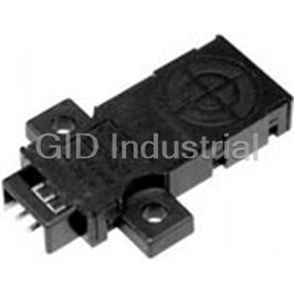
Control Unit
F3SJ-B££££P25 (continued)
Connection method: Prewired connector cable, F3SP-B1P
cable length 0.3 m, connector type (M12, 8-pin),
Applicable sensor F3SJ-B/A (Only for PNP output type)*
connector: IP67 rated (when mated)
Power cable
Power supply voltage 24 VDC ±10%
Number of wires: Emitter: 8 wires
Cable diameter: Dia. 6 mm DC1.7 W max. (not including sensor’s
Power supply consumption
current consumption)
Allowable bending radius: R5 mm
Extension cable 30 m max. 100 ms max. (not including sensor’s
Operation time
response time)
Case: Aluminum
100 ms max. (not including sensor’s
Cap: ABS resin, PBT
Response time
Material
response time)
Optical cover: PMMA resin (acrylic)
Cable: Oil resistant PVC
Number of
3NO + 1NC
Weight (packed state) Weight (g) = (protective height) x 2.7 + 500 contacts
Relay
250 VAC 5 A (cos = 1), 30 VDC 5 A L/R
Accessories Test rod, User’s Manual (CD-ROM) *7
output Rated load
= 0 ms
IEC 61496-1, EN 61496-1 UL 61496-1, Type 4
ESPE (Electro-Sensitive Protective Equipment) Rated current 5 A
IEC 61496-2, CLC/TS 61496-2, UL 61496-2,
Between sensors M12 connector (8-pin)
Connection
Type 4 AOPD (Active Opto-electronic Protective
type
Others Terminal block
Devices)
Applicable standards
Weight (packed state) Approx. 280 g
IEC 61508-1 to -3, EN 61508-1 to -3 SIL3
IEC 13849-1: 2006, EN ISO 13849-1: 2008 (PLe,
Accessories Instruction manual
Cat.4)
*NPN output type cannot be connected. Also, the system cannot be used
UL 508, UL 1998, CAN/CSA C22.2 No.14, CAN/
as a muting system.
CSA C22.2 No.0.8
Applications
Selecting the Best Configuration
Space Efficient and Low Cost
The built-in external device monitoring function
eliminates the need for a safety relay unit.
No Safety Relay Unit
F39-JD®A
G7SA Contactor Motor
Reduced Wiring and Easy Maintenance
Cables with connectors on both ends simplify
connections and prevent wiring errors.
Connector Type
F39-JD®B
Contactor
F3SP-B1P Motor
Dedicated controller
D-29 3
F3SJ-B Safety Light Curtains
Wiring
Basic Wiring Diagram
Wiring when using manual reset mode, external device monitoring
F39-JD@A-L F39-JD@A-D
(Gray) Communication line (+)
(Pink)
Communication line (−)
KM1
S1 S2
K1 KM2
KM1
KM2
+24 VDC
Power
supply
0 V
S1 : External test switch (connect to 0 V if a switch is not required)
S2 : Interlock/lockout reset switch
KM1, KM2 : Safety relay with force-guided contact (G7SA) or magnetic contactor
K1 : Load or PLC, etc. (for monitoring)
Wiring for auto reset mode and deactivated external device monitoring
F39-JD@A-L F39-JD@A-D
(Gray) Communication line (+)
(Pink)
Communication line (−)
S1 S2
K1 KM1 KM2
+24 VDC
Power
supply
0 V
S1 : External test switch (connect to 0 V if a switch is not required)
S2
: Lockout reset switch
KM1, KM2
: Safety relay with force-guided contact (G7SA) or magnetic contactor
K1 : Load or PLC, etc. (for monitoring)
D-30 4
Shield Shield
0 V (Blue)
0 V (Blue)
Not Used (Red)
Not Used (Red)
Interlock select input (White)
Interlock select input (White)
Test input (Black)
Test input (Black)
Emitter
Emitter
Reset input (Yellow)
Reset input (Yellow)
+24 V (Brown)
+24 V (Brown)
+24 V (Brown)
+24 V (Brown)
External device
External device
monitoring input (Red)
monitoring input (Red)
Auxiliary
Receiver
Receiver
output (Yellow)
Auxiliary output (Yellow)
Safety output 1 (Black)
Safety output 1 (Black)
Safety output 2 (White)
Safety output 2 (White)
0 V (Blue)
0 V (Blue)
Shield
Shield
F3SJ-B Safety Light Curtains
Dimensions (mm)
F3SJ-B/F3SJ-E Dimensions
The dimensions of the F3SJ-B and F3SJ-E are the same except for connector cables and cable leads.
Main Units
Mounting Top/Bottom and Intermediate Brackets
Backside mounting
Mounting screw holes
C (protective height): 4-digit number in the table
A = C + 69, B = C + 42.2
Top/Bottom Bracket 30
dia.9
19
(F39-LJB1) 19
43
D = C - 45, E = See table below, P = 20
6. 6.5 5
2-M8
4-M5
2
Number of
Protective
intermediate E
13
height
brackets
30
30 185 to 1,105 0 —
30
1,185 to 1,345 1 C/2 max.
22
7
22 22
Intermediate
1,425 to 2,065 2 C/3 max.
Bracket
(F39-LJB2)
2-M5 2-M5
Top/Bottom
Bracket
(F39-LJB1)
Mounting screw holes C (protective height): 4-digit number in the table
Side mounting
A = C + 69, B = C + 42.2
30
Top/Bottom dia.9
19
Bracket
46 19 D = C - 45, E = See table below, P = 20
(F39-LJB1)
6.5 2-M8
30
4-M5
Number of
Protective
intermediate E
height
brackets
30
185 to 1,105 0 —
1,185 to 1,345 1 C/2 max.
Intermediate
7
Bracket
22 22
(F39-LJB2)
1,425 to 2,065 2 C/3 max.
2-M5 2-M5
34
42
Top/Bottom
16
Bracket
(F39-LJB1)
12
Dimensions of top/bottom bracket
for F39-LJB1
45
dia.9
6.5
19
16
Material : Stainless
30
D-31 5
53
42
5.5
18.3
45
7.5
E 34.5 C (Protective height)
13.4 B
22.5
D
A
53 18.3
42
P (beam gap)
C (Protective height)
22.5
D
E
7.5
B
13.4
A
34.5
42
42
E E
C C
B B
42 42
E E
5.9 C 5.9 5.9 C 5.9
B
B
34.5
4.3
18.3
7.5
2
43
5.5
F3SJ-B Safety Light Curtains
Dimensions (continued) (mm)
Main Units
When Using Quick Mount Brackets
Backside mounting Mounting screw holes
C (protective height): 4-digit number in the table
F = See the table below.
43
30
Quick Mount Bracket
30
(F39-LJB3-M6 or
Number of
F39-LJB3-M8)
Protective
intermediate F
2-M6 2-M8
height
brackets
185 to 1,105 2 555 mm max.
1,185 to 1,585 3 555 mm max.
1,665 to 2,065 4 555 mm max.
Quick Mount Bracket
(F39-LJB3-M6 or
15
F39-LJB3-M8)
Side mounting Mounting screw holes
45
Quick Mount Bracket 16 30
33
(F39-LJB3-M6 or
F39-LJB3-M8)
C (protective height): 4-digit number in the table
F = See the table below.
2-M6 2-M8
Number of
Protective
intermediate F
height
brackets
185 to 1,105 2 555 mm max.
1,185 to 1,585 3 555 mm max.
Quick Mount Bracket
1,665 to 2,065 4 555 mm max.
(F39-LJB3-M6 or
F39-LJB3-M8)
3
12
Dimensions of quick mount bracket for F39-LJB3
Backside mounting Side mounting
80
80
dia.22
(32.1) (32.1)
(32.1)
(32.1)
dia.22
dia.22
dia.22
26
30
Material : Zinc die-cast
53
Quick mount M6 bracket Quick mount M8 bracket
53
Material : Zinc die-cast
dia.8.2
dia.6.2
dia.13
dia.17
1.5 1.5
8 8
Material : Stainless
Material : Stainless
D-32 6
45
30
15
22
(35.7)
(31.5)
F
275 max 275 max
8
C (Protective height)
(13)
275 max F 275 max
22
C (Protective height)
32.1 F 32.1
32.1 F 32.1
C
45 C
30
15
32.1 F 32.1
32.1 F 32.1
C
C
(46)
8
(16)
F3SJ-B Safety Light Curtains
Ordering
Main Units
Safety Light Curtains
Model
Protective height
Application Detection capability Beam gap Operating range (mm) PNP output
Hand protection Dia. 25 mm 20 mm 0.2 to 7 m 185 to 2,065 F3SJ-B££££P25
Safety Light Curtain Model List
Please contact our sales representatives.
F3SJ-B Series (20 mm pitch)
Protective height Protective height
Model Number of beams [mm] * Model Number of beams [mm] *
F3SJ-B0185P25 8 185 F3SJ-B1185P25 58 1,185
F3SJ-B0225P25 10 225 F3SJ-B1265P25 62 1,265
F3SJ-B0305P25 14 305 F3SJ-B1345P25 66 1,345
F3SJ-B0385P25 18 385 F3SJ-B1425P25 70 1,425
F3SJ-B0465P25 22 465 F3SJ-B1505P25 74 1,505
F3SJ-B0545P25 26 545 F3SJ-B1585P25 78 1,585
F3SJ-B0625P25 30 625 F3SJ-B1665P25 82 1,665
F3SJ-B0705P25 34 705 F3SJ-B1745P25 86 1,745
F3SJ-B0785P25 38 785 F3SJ-B1825P25 90 1,825
F3SJ-B0865P25 42 865 F3SJ-B1905P25 94 1,905
F3SJ-B0945P25 46 945 F3SJ-B1985P25 98 1,985
F3SJ-B1025P25 50 1,025 F3SJ-B2065P25 102 2,065
F3SJ-B1105P25 54 1,105
*Protective height (mm) = Total sensor length
Accessories (sold separately)
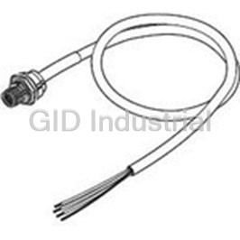
Single-end Connector Cable (2 cables per set, for emitter and receiver)
For wiring with safety circuit such as single safety relay, safety relay unit, and safety controller.
Appearance Cable length Specifications Model
3 m F39-JD3A
7 m F39-JD7A
10 m M12 connector (8-pin) F39-JD10A
15 m F39-JD15A
20 m F39-JD20A
Double-end Connector Cable (2 cables per set, for emitter and receiver)
Control unit for connection with F3SP-B1P, to extend the length under series connection.*
Appearance Cable length Specifications Model
0.5 m F39-JDR5B
1 m F39-JD1B
3 m F39-JD3B
5 m F39-JD5B
M12 connector (8-pin)
7 m F39-JD7B
10 m F39-JD10B
15 m F39-JD15B
20 m F39-JD20B
*To extend the cable length under series connection, use F39-JBR2W and F39-JD£B in combination. Also, the cable length 10 to 20 m cannot be used.
D-33 7
F3SJ-B Safety Light Curtains
Ordering (continued)
Accessories (sold separately) (continued)
Series-connection Cable (2 cables per set, for emitter and receiver)
Type Appearance Cable length Model Application
Series connection
0.2 m F39-JBR2W *1 For series connection *2
cable for extension
To change series connection length in
Extension cable 0.5 to 7 m F39-JD£B
combination with F39-JBR2W
*1. This product is for F3SJ-B only.
*2. Total cable length of series connection is 0.5 m to connect to connector cable of the main sensor unit.
Relays with Forcibly Guided Contacts
Type Appearance Specifications Model Remarks
• Nodes: 4
• Contact type: 2A2B
G7SA-2A2B
• Rated switch load:
For information on the
250 VAC 6A, 30 VDC 6A
G7SA Relays with
G7SA, contact Omron
✎
Forcibly Guided Contacts
• Nodes: 4
or visit website.
• Contact type: 3NO+1NC
G7SA-3A1B
• Rated switch load:
250 VAC 6A, 30 VDC 6A
• Nodes: 6
• Contact type: 4NO+2NC
G7S-4A2B-E
• Rated switch load:
250 VAC 10 A, 30 VDC 10 A
For information on
G7S-£-E Relays with
the G7S-£-E, contact
✎
Forcibly Guided Contacts
• Nodes: 6
Omron or visit website
• Contact type: 3NO+3NC
G7S-3A3B-E
• Rated switch load:
250 VAC 10 A, 30 VDC 10 A
Laser Pointer
Appearance Description Model
Laser Pointer for F3SJ F39-PTJ
Key Cap for Muting
Appearance Description Model
Muting key cap for F3SJ-B F39-CN10
D-34 8
F3SJ-B Safety Light Curtains
Ordering (continued)
Accessories (sold separately) (continued)
Sensor Mounting Bracket (sold separately)
Appearance Specifications Model Application Remarks
2 for the emitter,
Top/bottom bracket F39-LJB1 Top/bottom bracket for F3SJ-E/B 2 for the receiver,
total of 4 per set
In combination use with top/bottom
bracket for F3SJ-E/B
Intermediate bracket F39-LJB2 *1 *2 1 set with 2 pieces
Can be used as free-location
bracket.
Quick mount bracket for F3SJ-E/B
F39-LJB3-M6 *1 Supports M6 slide nut for aluminum
frame.
Quick mount bracket 1 set with 2 pieces
Quick mount bracket for F3SJ-E/B
F39-LJB3-M8 *2 Supports M8 slide nut for aluminum
frame.
Hexagon socket head
M6 slide nut F39-LJB3-M6K *1 cap screws (M6 x 10)
are included.
Spare slide nut for use with Quick
mount bracket.
Hexagon socket head
M8 slide nut F39-LJB3-M8K *2 cap screws (M8 x 14)
are included.
Mounting bracket used when
2 for the emitter,
replacing existing area sensors
Compatible mounting bracket F39-LJB4 2 for the receiver,
(F3SJ-A or F3SN) with the
total of 4 per set
F3SJ-E/B.
Note: All the sensor mounting brackets for the F3SJ-E are sold separately.
*1. Combining F39-LJB2 and F39-LJB3-M6K makes F39-LJB3-M6.
*2. Combining F39-LJB2 and F39-LJB3-M8K makes F39-LJB3-M8.
D-35 9
F3SJ-B Safety Light Curtains
Ordering (continued)
Accessories (sold separately) (continued)
Spatter Protection Cover (2 cables per set, common for emitter/receiver)
Appearance Model
F39-HB££££*1 *2
*1. The same 4-digit numbers as the protective heights (££££ in the light curtain model names) are substituted in the model names.
*2. It cannot be mounted to the models with the suffix “-02TS”.
Protective Bar
Appearance Model Remarks
• 2 light curtain brackets
• 4 mounting brackets
• 0 to 4 intermediate brackets for backside mounting
F39-PB££££*1
(quantity required for the sensing width)
• 0 to 4 intermediate brackets for mounting to the sides
(quantity required for the sensing width)
• 1 light curtain bracket
• 2 mounting brackets
• 0 to 2 intermediate brackets for backside mounting
F39-PB££££-S *1 *2
(quantity required for the sensing width)
• 0 to 2 intermediate brackets for mounting to the sides
(quantity required for the sensing width)
Note: The following are not provided with the protective bars: Safety Light Curtain, Safety Light Curtain Top/Bottom Brackets, Wall Mounting Screw Unit
*1. The same 4-digit numbers indicating the protective height that is used in the Sensor model number (££££) are used in the part of the Protector model
number.
*2. Purchase the F39-PB££££ (which contains two sets of brackets) to use Protective Bars for both the Emitter and Receiver.
D-36 10
Terms and Conditions of Sale
1. Offer; Acceptance. These terms and conditions (these "Terms") are deemed
ITY OR FITNESS FOR A PARTICULAR PURPOSE OF THE PRODUCTS.
part of all quotes, agreements, purchase orders, acknowledgments, price lists, BUYER ACKNOWLEDGES THAT IT ALONE HAS DETERMINED THAT THE
catalogs, manuals, brochures and other documents, whether electronic or in PRODUCTS WILL SUITABLY MEET THE REQUIREMENTS OF THEIR
writing, relating to the sale of products or services (collectively, the "Products") INTENDED USE. Omron further disclaims all warranties and responsibility of
by Omron Electronics LLC and its subsidiary companies (“Omron”). Omron any type for claims or expenses based on infringement by the Products or oth-
objects to any terms or conditions proposed in Buyer’s purchase order or other erwise of any intellectual property right. (c) Buyer Remedy. Omron’s sole obli-
documents which are inconsistent with, or in addition to, these Terms. gation hereunder shall be, at Omron’s election, to (i) replace (in the form
2. Prices; Payment Terms. All prices stated are current, subject to change with- originally shipped with Buyer responsible for labor charges for removal or
out notice by Omron. Omron reserves the right to increase or decrease prices replacement thereof) the non-complying Product, (ii) repair the non-complying
on any unshipped portions of outstanding orders. Payments for Products are Product, or (iii) repay or credit Buyer an amount equal to the purchase price of
due net 30 days unless otherwise stated in the invoice. the non-complying Product; provided that in no event shall Omron be responsi-
3. Discounts. Cash discounts, if any, will apply only on the net amount of invoices ble for warranty, repair, indemnity or any other claims or expenses regarding
sent to Buyer after deducting transportation charges, taxes and duties, and will the Products unless Omron’s analysis confirms that the Products were prop-
be allowed only if (i) the invoice is paid according to Omron’s payment terms erly handled, stored, installed and maintained and not subject to contamina-
and (ii) Buyer has no past due amounts. tion, abuse, misuse or inappropriate modification. Return of any Products by
4. Interest. Omron, at its option, may charge Buyer 1-1/2% interest per month or Buyer must be approved in writing by Omron before shipment. Omron Compa-
the maximum legal rate, whichever is less, on any balance not paid within the nies shall not be liable for the suitability or unsuitability or the results from the
stated terms. use of Products in combination with any electrical or electronic components,
5. Orders. Omron will accept no order less than $200 net billing. circuits, system assemblies or any other materials or substances or environ-
6. Governmental Approvals. Buyer shall be responsible for, and shall bear all ments. Any advice, recommendations or information given orally or in writing,
costs involved in, obtaining any government approvals required for the impor-
are not to be construed as an amendment or addition to the above warranty.
tation or sale of the Products. See http://www.omron247.com or contact your Omron representative for pub-
7. Taxes. All taxes, duties and other governmental charges (other than general lished information.
real property and income taxes), including any interest or penalties thereon, 14. Limitation on Liability; Etc. OMRON COMPANIES SHALL NOT BE LIABLE
imposed directly or indirectly on Omron or required to be collected directly or FOR SPECIAL, INDIRECT, INCIDENTAL, OR CONSEQUENTIAL DAMAGES,
indirectly by Omron for the manufacture, production, sale, delivery, importa- LOSS OF PROFITS OR PRODUCTION OR COMMERCIAL LOSS IN ANY
tion, consumption or use of the Products sold hereunder (including customs WAY CONNECTED WITH THE PRODUCTS, WHETHER SUCH CLAIM IS
duties and sales, excise, use, turnover and license taxes) shall be charged to BASED IN CONTRACT, WARRANTY, NEGLIGENCE OR STRICT LIABILITY.
and remitted by Buyer to Omron. Further, in no event shall liability of Omron Companies exceed the individual
8. Financial. If the financial position of Buyer at any time becomes unsatisfactory price of the Product on which liability is asserted.
to Omron, Omron reserves the right to stop shipments or require satisfactory 15. Indemnities. Buyer shall indemnify and hold harmless Omron Companies and
security or payment in advance. If Buyer fails to make payment or otherwise their employees from and against all liabilities, losses, claims, costs and
comply with these Terms or any related agreement, Omron may (without liabil- expenses (including attorney's fees and expenses) related to any claim, inves-
ity and in addition to other remedies) cancel any unshipped portion of Prod- tigation, litigation or proceeding (whether or not Omron is a party) which arises
ucts sold hereunder and stop any Products in transit until Buyer pays all or is alleged to arise from Buyer's acts or omissions under these Terms or in
amounts, including amounts payable hereunder, whether or not then due, any way with respect to the Products. Without limiting the foregoing, Buyer (at
which are owing to it by Buyer. Buyer shall in any event remain liable for all its own expense) shall indemnify and hold harmless Omron and defend or set-
unpaid accounts. tle any action brought against such Companies to the extent based on a claim
9. Cancellation; Etc. Orders are not subject to rescheduling or cancellation that any Product made to Buyer specifications infringed intellectual property
unless Buyer indemnifies Omron against all related costs or expenses. rights of another party.
. Omron shall not be liable for any delay or failure in delivery Any intellectual property in the Products is the exclu-
10. Force Majeure 16. Property; Confidentiality.
resulting from causes beyond its control, including earthquakes, fires, floods, sive property of Omron Companies and Buyer shall not attempt to duplicate it
strikes or other labor disputes, shortage of labor or materials, accidents to in any way without the written permission of Omron. Notwithstanding any
machinery, acts of sabotage, riots, delay in or lack of transportation or the charges to Buyer for engineering or tooling, all engineering and tooling shall
requirements of any government authority. remain the exclusive property of Omron. All information and materials supplied
11. Shipping; Delivery. Unless otherwise expressly agreed in writing by Omron: by Omron to Buyer relating to the Products are confidential and proprietary,
a. Shipments shall be by a carrier selected by Omron; Omron will not drop ship and Buyer shall limit distribution thereof to its trusted employees and strictly
except in “break down” situations. prevent disclosure to any third party.
b. Such carrier shall act as the agent of Buyer and delivery to such carrier shall 17. Export Controls. Buyer shall comply with all applicable laws, regulations and
constitute delivery to Buyer; licenses regarding (i) export of products or information; (iii) sale of products to
c. All sales and shipments of Products shall be FOB shipping point (unless oth- “forbidden” or other proscribed persons; and (ii) disclosure to non-citizens of
erwise stated in writing by Omron), at which point title and risk of loss shall regulated technology or information.
pass from Omron to Buyer; provided that Omron shall retain a security inter- 18. Miscellaneous. (a) Waiver. No failure or delay by Omron in exercising any right
est in the Products until the full purchase price is paid; and no course of dealing between Buyer and Omron shall operate as a waiver
d. Delivery and shipping dates are estimates only; and of rights by Omron. (b) Assignment. Buyer may not assign its rights hereunder
e.Omron will package Products as it deems proper for protection against nor- without Omron's written consent. (c) Law. These Terms are governed by the
mal handling and extra charges apply to special conditions. law of the jurisdiction of the home office of the Omron company from which
12. Claims. Any claim by Buyer against Omron for shortage or damage to the Buyer is purchasing the Products (without regard to conflict of law princi-
Products occurring before delivery to the carrier must be presented in writing ples). (d) Amendment. These Terms constitute the entire agreement between
to Omron within 30 days of receipt of shipment and include the original trans- Buyer and Omron relating to the Products, and no provision may be changed
. If any provi-
portation bill signed by the carrier noting that the carrier received the Products or waived unless in writing signed by the parties. (e) Severability
from Omron in the condition claimed. sion hereof is rendered ineffective or invalid, such provision shall not invalidate
13. Warranties. (a) Exclusive Warranty. Omron’s exclusive warranty is that the any other provision. (f) Setoff. Buyer shall have no right to set off any amounts
Products will be free from defects in materials and workmanship for a period of against the amount owing in respect of this invoice. (g) Definitions. As used
twelve months from the date of sale by Omron (or such other period expressed herein, “including” means “including without limitation”; and “Omron Compa-
in writing by Omron). Omron disclaims all other warranties, express or implied. nies” (or similar words) mean Omron Corporation and any direct or indirect
(b) Limitations. OMRON MAKES NO WARRANTY OR REPRESENTATION, subsidiary or affiliate thereof.
EXPRESS OR IMPLIED, ABOUT NON-INFRINGEMENT, MERCHANTABIL-
Certain Precautions on Specifications and Use
1. Suitability of Use. Omron Companies shall not be responsible for conformity ADDRESS THE RISKS, AND THAT THE OMRON’S PRODUCT IS PROP-
with any standards, codes or regulations which apply to the combination of the ERLY RATED AND INSTALLED FOR THE INTENDED USE WITHIN THE
Product in the Buyer’s application or use of the Product. At Buyer’s request, OVERALL EQUIPMENT OR SYSTEM.
Omron will provide applicable third party certification documents identifying 2. Programmable Products. Omron Companies shall not be responsible for the
ratings and limitations of use which apply to the Product. This information by user’s programming of a programmable Product, or any consequence thereof.
itself is not sufficient for a complete determination of the suitability of the Prod- 3. Performance Data. Data presented in Omron Company websites, catalogs
uct in combination with the end product, machine, system, or other application and other materials is provided as a guide for the user in determining suitabil-
or use. Buyer shall be solely responsible for determining appropriateness of ity and does not constitute a warranty. It may represent the result of Omron’s
the particular Product with respect to Buyer’s application, product or system. test conditions, and the user must correlate it to actual application require-
Buyer shall take application responsibility in all cases but the following is a ments. Actual performance is subject to the Omron’s Warranty and Limitations
non-exhaustive list of applications for which particular attention must be given: of Liability.
(i) Outdoor use, uses involving potential chemical contamination or electrical 4. Change in Specifications. Product specifications and accessories may be
interference, or conditions or uses not described in this document. changed at any time based on improvements and other reasons. It is our prac-
(ii) Use in consumer products or any use in significant quantities. tice to change part numbers when published ratings or features are changed,
(iii) Energy control systems, combustion systems, railroad systems, aviation or when significant construction changes are made. However, some specifica-
systems, medical equipment, amusement machines, vehicles, safety equip- tions of the Product may be changed without any notice. When in doubt, spe-
ment, and installations subject to separate industry or government regulations. cial part numbers may be assigned to fix or establish key specifications for
(iv) Systems, machines and equipment that could present a risk to life or prop- your application. Please consult with your Omron’s representative at any time
erty. Please know and observe all prohibitions of use applicable to this Prod- to confirm actual specifications of purchased Product.
uct. 5. Errors and Omissions. Information presented by Omron Companies has been
NEVER USE THE PRODUCT FOR AN APPLICATION INVOLVING SERIOUS checked and is believed to be accurate; however, no responsibility is assumed
RISK TO LIFE OR PROPERTY OR IN LARGE QUANTITIES WITHOUT for clerical, typographical or proofreading errors or omissions.
ENSURING THAT THE SYSTEM AS A WHOLE HAS BEEN DESIGNED TO
OMRON AUTOMATION AND SAFETY • THE AMERICAS HEADQUARTERS • Hoffman Estates, IL USA • 847.843.7900 • 800.556.6766 • www.omron247.com
OMRON CANADA, INC. • HEAD OFFICE OMRON ARGENTINA • SALES OFFICE
Toronto, ON, Canada • 416.286.6465 • 866.986.6766 • www.omron247.com Cono Sur • 54.11.4783.5300
OMRON ELECTRONICS DE MEXICO • HEAD OFFICE OMRON CHILE • SALES OFFICE
México DF • 52.55.59.01.43.00 • 01-800-226-6766 • mela@omron.com Santiago • 56.9.9917.3920
OMRON ELECTRONICS DE MEXICO • SALES OFFICE OTHER OMRON LATIN AMERICA SALES
Apodaca, N.L. • 52.81.11.56.99.20 • 01-800-226-6766 • mela@omron.com 54.11.4783.5300
OMRON ELETRÔNICA DO BRASIL LTDA • HEAD OFFICE
São Paulo, SP, Brasil • 55.11.2101.6300 • www.omron.com.br
OMrOn EurOPE B.V. • Wegalaan 67-69, NL-2132 JD, Hoofddorp, The Netherlands. • +31 (0) 23 568 13 00 • www.industrial.omron.eu
Authorized Distributor: Automation Control Systems
• Machine Automation Controllers (MAC) • Programmable Controllers (PLC)
• Operator interfaces (HMI) • Distributed I/O • Software
Drives & Motion Controls
• Servo & AC Drives • Motion Controllers & Encoders
Temperature & Process Controllers
• Single and Multi-loop Controllers
Sensors & Vision
• Proximity Sensors • Photoelectric Sensors • Fiber-Optic Sensors
• Amplified Photomicrosensors • Measurement Sensors
• Ultrasonic Sensors • Vision Sensors
Industrial Components
• RFID/Code Readers • Relays • Pushbuttons & Indicators
• Limit and Basic Switches • Timers • Counters • Metering Devices
• Power Supplies
Safety
• Laser Scanners • Safety Mats • Edges and Bumpers • Programmable Safety
Controllers • Light Curtains • Safety Relays • Safety Interlock Switches
F3SJ-B F24I-E-01 Note: Specifications are subject to change. © 2014 Omron Electronics LLC Printed in U.S.A.
Printed on recycled paper.


 Manufacturers


What they say about us
FANTASTIC RESOURCE
One of our top priorities is maintaining our business with precision, and we are constantly looking for affiliates that can help us achieve our goal. With the aid of GID Industrial, our obsolete product management has never been more efficient. They have been a great resource to our company, and have quickly become a go-to supplier on our list!
Bucher Emhart Glass
EXCELLENT SERVICE
With our strict fundamentals and high expectations, we were surprised when we came across GID Industrial and their competitive pricing. When we approached them with our issue, they were incredibly confident in being able to provide us with a seamless solution at the best price for us. GID Industrial quickly understood our needs and provided us with excellent service, as well as fully tested product to ensure what we received would be the right fit for our company.
Fuji
HARD TO FIND A BETTER PROVIDER
Our company provides services to aid in the manufacture of technological products, such as semiconductors and flat panel displays, and often searching for distributors of obsolete product we require can waste time and money. Finding GID Industrial proved to be a great asset to our company, with cost effective solutions and superior knowledge on all of their materials, it’d be hard to find a better provider of obsolete or hard to find products.
Applied Materials
CONSISTENTLY DELIVERS QUALITY SOLUTIONS
Over the years, the equipment used in our company becomes discontinued, but they’re still of great use to us and our customers. Once these products are no longer available through the manufacturer, finding a reliable, quick supplier is a necessity, and luckily for us, GID Industrial has provided the most trustworthy, quality solutions to our obsolete component needs.
Nidec Vamco
TERRIFIC RESOURCE
This company has been a terrific help to us (I work for Trican Well Service) in sourcing the Micron Ram Memory we needed for our Siemens computers. Great service! And great pricing! I know when the product is shipping and when it will arrive, all the way through the ordering process.
Trican Well Service
GO TO SOURCE
When I can't find an obsolete part, I first call GID and they'll come up with my parts every time. Great customer service and follow up as well. Scott emails me from time to time to touch base and see if we're having trouble finding something.....which is often with our 25 yr old equipment.
ConAgra Foods