

 Manufacturers
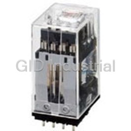
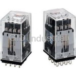
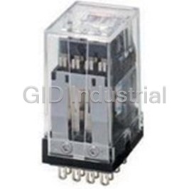
OMRON AUTOMATION G2A-432A-US-AC100/110
Description
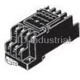
Power Relay 100/110VAC 0.5A 4PDT(28.5x21.5x42.5)mm Socket
G2A-432A-US-AC100/110
Part Number
G2A-432A-US-AC100/110
Price
Request Quote
Manufacturer
OMRON AUTOMATION
Lead Time
Request Quote
Category
Relays and I/O Modules » Power Relay
Specifications
Manufacturer
Omron Automation
Manufacturers Part #
G2A-432A-US-AC100/110
Industry Aliases
G2A-432A-US-AC100/110
Sub-Category
Power Relays
Factory Pack Quantity
10
Datasheet

Extracted Text
Power Relay G2A CSM_G2A_DS_E_3_1 Highly Reliable, 4-pole Miniature Relay Ideal for Sequence Control • Card lift-off employed for greater life and stable quality. Long endurance and stable quality are assured by card lift-off system. Mounting interchangeability with MY-series Relays. Operation indicator mechanism incorporated for at-a-glance monitoring of ON/OFF operation. In addition, a built-in operation indicator model is also included in this Relay Series. Ordering Information Classification Plug-in terminals/Solder terminals PCB terminals Standard model G2A-432A G2A-4321P Arc barrier equipped model G2A-432AY --- Built-in diode model G2A-432A-D G2A-4321P-D Built-in operation indicator model G2A-432A-N --- Built-in operation indicator and diode model G2A-432A-N1 --- Note: 1. When placing your order, add the coil voltage rating listed in the specifications to the model number as shown below. Example: G2A-432A 100/110 VAC Rated coil voltage 2. Built-in diode model and the operating coil of the G2A-432A-N1 are available only with DC ratings. 3. The Latching Relay (G2AK) and Fully sealed Relay (G2A-434A) developed based on the G2A are also available in this se- ries. Model Number Legend G2A-@@@@@-@ 1 2 3 4 5 6 1. Number of Poles and Contact Form 5. Safety Breaking Mechanism 4: 4PDT None: No 2. Contact Type Y: Arc barrier 3: Crossbar bifurcated 6. Special Element 3. Enclosure Construction None: Standard 2: Casing D: Built-in diode 4. Terminal Shape N: Built-in operation indicator A: Plug-in N1: Built-in operation indicator and diode 1P: PCB Note: 1. The coil of the G2A-432A-N1 or a built-in diode model operates with DC only. 2. The G2A Series include the G2A-434A Power Relay and G2AK Latching Relay. Refer to G2A-434 and G2AK for details. 1 G2A ■ Relays Other than Standard Models Arc barrier equipped Built-in diode Built-in operation indicator G2A-432AY G2A-432A-D G2A-432A-N The arc barrier equipped model is The built-in diode model is a relay The built-in operation indicator a relay designed to prevent arc which incorporates a diode for ab- model has a newly added opera- short-circuiting between phases sorption of the reverse voltage tion indicator to the conventional and can be used in a circuit which that may be generated when the operation indication mechanism has potential difference between coil is de-energized. Because the and facilitates operation monitor- phases. The switching power of release time of this model is long- ing without being affected by am- such a circuit with potential differ- er than the standard model, pay bient illumination. ence must be limited to less than adequate attention to this point in With the -N model (rated at 16, 1/2 the rated load when using this designing a circuit. Also, pay at- 12, 24, and 48 VDC) and -N1 Relay. tention to the + polarity of the coil. model rated at 6, 12, 24, 48, and The reverse-breakdown voltage 100 VDC), pay attention to the + of the diode is 1,000 V. polarity of the coil. ■ Accessories Sockets Track mounting Front-connecting Socket Screw terminals Solder terminals Wire-wrap terminals PCB terminals Without Hold- With Hold-down Without Hold- With Hold-down down Clip Clip down Clip Clip PYF14A PYF14(-E), PYF14A- PY14, PY14-3 PY14-Y2 PY14QN(2) PY14QN(2)-Y2 PY14-0, TU, PYF14T (see note) PY14-02 Note:With monitor terminal. Relay Hold-down Clips Socket Mounting Plates For Front-connecting Socket PYC-A2 For one Socket PYP-1 For Back-connecting Socket PYC-3/PYC-5 For 18 Sockets PYP-18 For Socket Mounting Plate PYC-2 For 36 Sockets PYP-38 Specifications ■ Coil Ratings The rated currents for some of the built-in operation indicator models differ from the values given in this table. Refer to note 5 below. Rated Rated current Coil Coil inductance (ref. Must Must Max. Power voltage resistance value) operate release voltage consumption 50 Hz 60 Hz Armature Armature % of rated voltage OFF ON 6 VAC 295 mA 233 mA 8.9 Ω 0.048 H 0.065 H 80 % max. 30 % min. 110 % Approx. 1.4 VA 12 VAC 148 mA 117 mA 34 Ω 0.166 H 0.257 H 24 VAC 73 mA 58 mA 136 Ω 0.691 H 1.04 H 50 VAC 35 mA 28 mA 530 Ω 3.08 H 4.53 H 100/ 17.7/ 14/ 2,200 Ω 12.42/ 18/16.4 H 110 VAC 21.4 mA 16.8 mA 12.38 H 200/ 8.9/ 7/8.4 mA 8,800 Ω 42.2/ 72/65.5 H 220 VAC 10.8 mA 41.8 H 6 VDC 176 mA 34 Ω 0.14 H 0.26 H 10 % min. 110 % Approx. 1.1 W 12 VDC 88 mA 136 Ω 0.6 H 1.0 H 24 VDC 45 mA 530 Ω 2.7 H 4.6 H 48 VDC 22 mA 2,200 Ω 11 H 19 H 100 VDC 11.4 mA 8,800 Ω 43 H 73 H Note: 1. The rated current and coil resistance are measured at a coil temperature of 23°C with tolerances of +15%/–20% for AC rated current and ±15% for DC coil resistance. 2. The AC coil resistance and coil inductance values are for reference only. 3. Performance characteristic data is measured at a coil temperature of 23°C. 4. The maximum voltage is one that is applicable instantaneously to the Relay coil at an ambient temperature of 23°C and not continuously. 5. For built-in operation indicator models rated at 6, 12, and 24 VDC, add an LED current of approx. 5 mA to the rated currents. 2 G2A ■ Contact Ratings Load Resistive load (cosφ = 1) Inductive load (cosφ = 0.4) (L/R = 7 ms) Contact type Crossbar bifurcated Contact material Movable: AgAu-clad AgPd Fixed: AgPd Rated load 0.3 A at 110 VAC 0.2 A at 110 VAC 0.5 A at 24 VDC 0.3 A at 24 VDC Rated carry current 3 A Max. switching power 250 VAC, 125 VDC ■ Characteristics Classification Standard/Acr barrier equipped/Built-in operation Built-in diode/Built-in operation indicator models indicator models (G2A-@-N) (G2A-@-N1) Contact resistance 100 mΩ max. (see note 2) Operate time (see note 3) 15 ms max. Release time (see note 3) 15 ms max. 30 ms max. Max. operating frequency Mechanical: 18,000 operations/hour Electrical: 1,800 operations/hour (under rated load) Insulation resistance 100 MΩ min. (at 500 VDC) (see note 4) Dielectric strength 1,500 VAC, 50/60 Hz for 1 min between coil and contacts and contacts of different polarities (700 VAC be- tween contacts of same polarity) Vibration resistance Destruction: 10 to 55 to 10 Hz, 0.75 mm single amplitude (1.5 mm double amplitude) Malfunction: 10 to 55 to 10 Hz, 0.5 mm single amplitude (1.0 mm double amplitude) 2 Shock resistance Destruction: 1,000 m/s 2 Malfunction: 100 m/s Error rate (level P) 1 mA at 100 mVDC (Reference value) (see note 6) Endurance Mechanical: 100,000,000 operations min. (at operating frequency of 18,000 operations/hour) Electrical: 5,000,000 operations min. (under rated load and at operating frequency of 1,800 operations/hour) (see note 5) Ambient temperature Operating:–10°C to 40°C (with no icing or condensation) Ambient humidity Operating:5% to 85% Weight Approx. 38 g Note: 1. The data shown above are initial values. 2. The contact resistance was measured with 0.1 A at 5 VDC using the voltage drop method. 3. The operate or release time was measured with the rated voltage imposed with any contact bounce ignored at an ambient temperature of 23°C. 4. The insulation resistance was measured with a 500-VDC megger applied to the same places as those used for checking the dielectric strength. 5. The electrical endurance was measured at an ambient temperature of 23°C. 6. This value was measured at a switching frequency of 60 operations per minute. 3 G2A Engineering Data Maximum Switching Power Endurance 10,000 5,000 DC resistive load 24-VDC resistive load 24-VDC 1,000 AC resistive load inductive load L/R = 7 ms 500 AC inductive load (cosφ = 0.4) 100 110-VAC 50 resistive load DC inductive load L/R = 7 ms 110-VAC inductive load 10 cosφ = 0.4 Switching voltage (V) Switching current (A) Ambient Temperature vs. Ambient Temperature vs. Must-operate and Must-release Coil Temperature Rise Malfunctioning Shock Voltage G2A-432A 100/110 VAC G2A AC (60 Hz) G2A 110 VAC (50 Hz) Contact Must-operate Not energized carry current voltage Number of Relays: 5 Number of Relays: 5 Must-release Energized voltage Ambient temperature (°C) Ambient temperature (°C) 2 Unit: m/s Shock direction G2A DC G2A DC Contact Must-operate carry current voltage Number of Relays: 5 Number of Relays: 5 Must-release voltage Number of samples = 5 Measurement conditions: Impose a shock of 2 100 m/s in the ±X, ±Y, and ±Z directions three times each with the Relay energized and not energized to check the shock values that cause the Relay to malfunction. Ambient temperature (°C) Ambient temperature (°C) 4 Must-operate and reset voltage (%) Must-operate and reset voltage (%) Switching current (A) ° Coil temperature rise ( C) ° Coil temperature rise ( C) Endurance (x10 operations) 3 G2A Contact Reliability Contact Reliability (Improved Allen-Bradley Test Circuit) (JIS C 4530 Allen-Bradley Test Circuit) Contact load: 1 mA at 5 VDC (resistive load) Failure criterion contact resistance: 100 Ω 24 VDC 100 VAC −6 −6 −6 λ60 = 0.00153 × 10 λ60 = 0.00153 × 10 λ60 = 0.00153 × 10 Carry contact Carry contact Carry contact Break contact Break contact Break contact Make contact Make contact Make contact Self-holding Self-holding Self-holding contact contact contact 4 4 4 Operations (x 10 ) Operations (x 10 ) Operations (x 10 ) Coil Self-load Life Curve (Unit: mA) Model Specifications No. of Relays 12 3 5 10 G2A-432A 100 VAC, 60 Hz 14 28 42 70 140 100 VAC 24 VDC 45 90 135 225 450 24 VDC Number of Relays Relay Mounting Adjacent Distance vs. Coil Temperature Rise G2A-432A 24 VDC 110 VAC Relay Relay mounting mounting Upper Upper position position Condition: The Condition: The saturated saturated coil coil temperature is measured with rated temperature is voltage (110 VAC) at 60 Hz measured with rated imposed. coil voltage (24 VDC) imposed. Lower Lower Average of No. 1 and No. 3 Average of No. 4. and No. 6 Average of No. 1 and No. 3 Average of No. 7 and No. 9 Average of No. 4. and No. 6 Average of No. 7 and No. 9 Mounting adjacent distance l (mm) Mounting adjacent distance l (mm) 5 Coil temperature rise ( C) ° Contact resistance (m ) Ω Contact resistance (m ) Ω Coil temperature rise ( C) ° 4 Life (x10 ) Contact resistance (m ) Ω G2A Accessories (Order Separately) Connecting Sockets Front-connecting Back-connecting Socket Socket DIN track/screw Solder terminals Wire-wrap terminals PCB terminals mounting PYF14A(-E) PY14 PY14-Y2 PY14QN(2)-Y2 PY14-0 PY14-02 PY14QN(2) PYF14A-TU PY14-Y3 (with Relay (with Relay PYF14T Hold-down Clip) Hold-down Clip) Note: 1. The PYF@A-TU is a high-humidity relay with nickel-plated rustproof terminal screws that are the same as the PYF@A in size. 2. The PYF14T is slightly different from the PYF14A(-TU) in shape and size. 3. The PYF@A-E is a finger-protection model, for which round terminals are not available. Use fork-shaped terminals or equivalent ones instead. PY14-3 Back-connecting Socket 81 Panel Cutout 9 (7.7) 56 2 (with check terminals for operation monitoring) 28 +0.3 78 −0 0.3 38.5 34.5±0.4 +0.3 36 −0 Check terminal for operation monitoring Built-in operation monitoring lamp possible +0 77.5 −0.4 2-dia. hole Shorting lead Three, 1.2-dia. holes Relay Mounting Height with Socket With Back-connecting Socket With Front-connecting Socket G2A G2A 45.5 73 76.5 PY14 Socket PYF14A Note: PYF14A can be used for both DIN track mounting and screw mounting. Relay Hold-down Clips For Front-connecting Socket For Back-connecting Socket For Socket mounting plate PYC-A2 PYC-3 PYC-5 PYC-2 Note: When using a Relay Hold-down Clip for the built-in operation indicator model, use of the PYC-A2 or PYC-5, which allows easy viewing of the indicator, is recommended. 6 G2A Dimensions Note: 1. All units are in millimeters unless otherwise indicated. 2. Dimensional tolerances are ±0.1 mm. Mounting Holes on PCB Solder Terminal Models PCB Terminal Models (Bottom View) 0.5 2.6 1 21.5 max. 21.5 max. 5 Fourteen, 1.5-dia. holes Fourteen, 1.2-dia. 1.2 holes x 3 elliptic holes 2.6 0.5 4.1 0.5 28.5 max. 12.65 28.5 max. 6.35 7.3 1.8 1.8 4.4 5.4 42.5 max. 4 42.5 max. 4.4 13.2 Terminal Arrangement/Internal Connections (Bottom View) Standard Models Make-before-break Arc Barrier Equipped Models Built-in Diode Models Contact Models Built-in Operation Indicator Models Color of operation indicator AC model: Red DC model: Green G2A-432A-N 100/110, 200/220 VAC 6, 12, 24 VDC 48, 100 VDC 6, 12, 24, 50 VDC G2A-432A-N1 6, 12, 24 VDC 48, 100 VDC Note: Do not reverse the polarity of the coil of DC Relays that have a built-in indicator or diode. 7 G2A Socket Mounting Plates (t = 1.6 mm) Use any of these plates when mounting two or more Sockets side-by-side PYP-1 (for Single Socket Mounting) PYP-18 (for Mounting 18 Sockets) PYP-36 (for Mounting 36 Sockets) 492 492 27.4 x 17 = 465.8±0.6 27.4 x 17 = 465.8±0.6 72 elliptic holes 13.1 21.6 13.1 27.4 72 elliptic holes 4.5 +0.2 Two, 3.4-dia. holes 21.6 4.5 ±0.15 R1.7 21.4 −0 27.4 3.4 ±0.15 R1.7 3.4 Square 42±0.1 49 39.7±0.2 hole 49 42±0.1 86.4 28 39.7±0.2 Note: PYP-18 and PYP-36 can be cut to a desired length for mounting less than 18 or 36 Sockets, respectively. 13.1 21.6 27.4 x 17 = 465.8±0.6 Safety Precautions Refer to Safety Precautions for All Relays. A DC coil model with a built-in indicator or built-in diode has coil polarity. Be sure to wire the terminals correctly, otherwise the diode may be broken or the operating indicator may not be lit. Furthermore, as a result of the short-circuiting of the built-in diode, the devices in the circuit may be damaged. ALL DIMENSIONS SHOWN ARE IN MILLIMETERS. To convert millimeters into inches, multiply by 0.03937. To convert grams into ounces, multiply by 0.03527. In the interest of product improvement, specifications are subject to change without notice. 8 Read and Understand This Catalog Please read and understand this catalog before purchasing the products. Please consult your OMRON representative if you have any questions or comments. Warranty and Limitations of Liability WARRANTY OMRON's exclusive warranty is that the products are free from defects in materials and workmanship for a period of one year (or other period if specified) from date of sale by OMRON. OMRON MAKES NO WARRANTY OR REPRESENTATION, EXPRESS OR IMPLIED, REGARDING NON-INFRINGEMENT, MERCHANTABILITY, OR FITNESS FOR PARTICULAR PURPOSE OF THE PRODUCTS. ANY BUYER OR USER ACKNOWLEDGES THAT THE BUYER OR USER ALONE HAS DETERMINED THAT THE PRODUCTS WILL SUITABLY MEET THE REQUIREMENTS OF THEIR INTENDED USE. OMRON DISCLAIMS ALL OTHER WARRANTIES, EXPRESS OR IMPLIED. LIMITATIONS OF LIABILITY OMRON SHALL NOT BE RESPONSIBLE FOR SPECIAL, INDIRECT, OR CONSEQUENTIAL DAMAGES, LOSS OF PROFITS OR COMMERCIAL LOSS IN ANY WAY CONNECTED WITH THE PRODUCTS, WHETHER SUCH CLAIM IS BASED ON CONTRACT, WARRANTY, NEGLIGENCE, OR STRICT LIABILITY. In no event shall the responsibility of OMRON for any act exceed the individual price of the product on which liability is asserted. IN NO EVENT SHALL OMRON BE RESPONSIBLE FOR WARRANTY, REPAIR, OR OTHER CLAIMS REGARDING THE PRODUCTS UNLESS OMRON'S ANALYSIS CONFIRMS THAT THE PRODUCTS WERE PROPERLY HANDLED, STORED, INSTALLED, AND MAINTAINED AND NOT SUBJECT TO CONTAMINATION, ABUSE, MISUSE, OR INAPPROPRIATE MODIFICATION OR REPAIR. Application Considerations SUITABILITY FOR USE OMRON shall not be responsible for conformity with any standards, codes, or regulations that apply to the combination of products in the customer's application or use of the products. At the customer's request, OMRON will provide applicable third party certification documents identifying ratings and limitations of use that apply to the products. This information by itself is not sufficient for a complete determination of the suitability of the products in combination with the end product, machine, system, or other application or use. The following are some examples of applications for which particular attention must be given. This is not intended to be an exhaustive list of all possible uses of the products, nor is it intended to imply that the uses listed may be suitable for the products: · Outdoor use, uses involving potential chemical contamination or electrical interference, or conditions or uses not described in this catalog. · Nuclear energy control systems, combustion systems, railroad systems, aviation systems, medical equipment, amusement machines, vehicles, safety equipment, and installations subject to separate industry or government regulations. · Systems, machines, and equipment that could present a risk to life or property. Please know and observe all prohibitions of use applicable to the products. NEVER USE THE PRODUCTS FOR AN APPLICATION INVOLVING SERIOUS RISK TO LIFE OR PROPERTY WITHOUT ENSURING THAT THE SYSTEM AS A WHOLE HAS BEEN DESIGNED TO ADDRESS THE RISKS, AND THAT THE OMRON PRODUCTS ARE PROPERLY RATED AND INSTALLED FOR THE INTENDED USE WITHIN THE OVERALL EQUIPMENT OR SYSTEM. PROGRAMMABLE PRODUCTS OMRON shall not be responsible for the user's programming of a programmable product, or any consequence thereof. Disclaimers CHANGE IN SPECIFICATIONS Product specifications and accessories may be changed at any time based on improvements and other reasons. It is our practice to change model numbers when published ratings or features are changed, or when significant construction changes are made. However, some specifications of the products may be changed without any notice. When in doubt, special model numbers may be assigned to fix or establish key specifications for your application on your request. Please consult with your OMRON representative at any time to confirm actual specifications of purchased products. DIMENSIONS AND WEIGHTS Dimensions and weights are nominal and are not to be used for manufacturing purposes, even when tolerances are shown. PERFORMANCE DATA Performance data given in this catalog is provided as a guide for the user in determining suitability and does not constitute a warranty. It may represent the result of OMRON’s test conditions, and the users must correlate it to actual application requirements. Actual performance is subject to the OMRON Warranty and Limitations of Liability. ERRORS AND OMISSIONS The information in this document has been carefully checked and is believed to be accurate; however, no responsibility is assumed for clerical, typographical, or proofreading errors, or omissions. 2010.8 In the interest of product improvement, specifications are subject to change without notice. OMRON Corporation Industrial Automation Company http://www.ia.omron.com/ (c)Copyright OMRON Corporation 2010 All Right Reserved.
Frequently asked questions
How does Electronics Finder differ from its competitors?

Is there a warranty for the G2A-432A-US-AC100/110?
Which carrier will Electronics Finder use to ship my parts?
Can I buy parts from Electronics Finder if I am outside the USA?
Which payment methods does Electronics Finder accept?
Why buy from GID?

Quality
We are industry veterans who take pride in our work

Protection
Avoid the dangers of risky trading in the gray market

Access
Our network of suppliers is ready and at your disposal

Savings
Maintain legacy systems to prevent costly downtime

Speed
Time is of the essence, and we are respectful of yours
Related Products
Power Relay 24VDC 0.5A 4PDT(28.5x21.5x42.5)mm Socket G2A-432A-DC24
Power Relay 48VDC 0.5A 4PDT(28.5x21.5x42.5)mm Socket G2A-432A-DC48
Power Relay 24VDC 0.5A 4PDT(28.5x21.5x42.5)mm Socket G2A-432A-D-DC24
Power Relay 48VDC 0.5A 4PDT(28.5x21.5x42.5)mm Socket G2A-432A-N-US-DC48
Power Relay 100/110VAC 3A 4PDT(28.5x21.5x42.5)mm Socket G2A-434A-AC100/110
Power Relay 110VAC 10A SPST-NO (( 45mm 14mm 29.5mm)) Bracket Mount G2R-1A-T-AC110
Request a Quote

The quote request has been received
Close

Facing challenges or have inquiries? Feel free to contact us!
Call Us +1-469-283-2440
What they say about us
FANTASTIC RESOURCE
One of our top priorities is maintaining our business with precision, and we are constantly looking for affiliates that can help us achieve our goal. With the aid of GID Industrial, our obsolete product management has never been more efficient. They have been a great resource to our company, and have quickly become a go-to supplier on our list!
Bucher Emhart Glass
EXCELLENT SERVICE
With our strict fundamentals and high expectations, we were surprised when we came across GID Industrial and their competitive pricing. When we approached them with our issue, they were incredibly confident in being able to provide us with a seamless solution at the best price for us. GID Industrial quickly understood our needs and provided us with excellent service, as well as fully tested product to ensure what we received would be the right fit for our company.
Fuji
HARD TO FIND A BETTER PROVIDER
Our company provides services to aid in the manufacture of technological products, such as semiconductors and flat panel displays, and often searching for distributors of obsolete product we require can waste time and money. Finding GID Industrial proved to be a great asset to our company, with cost effective solutions and superior knowledge on all of their materials, it’d be hard to find a better provider of obsolete or hard to find products.
Applied Materials
CONSISTENTLY DELIVERS QUALITY SOLUTIONS
Over the years, the equipment used in our company becomes discontinued, but they’re still of great use to us and our customers. Once these products are no longer available through the manufacturer, finding a reliable, quick supplier is a necessity, and luckily for us, GID Industrial has provided the most trustworthy, quality solutions to our obsolete component needs.
Nidec Vamco
TERRIFIC RESOURCE
This company has been a terrific help to us (I work for Trican Well Service) in sourcing the Micron Ram Memory we needed for our Siemens computers. Great service! And great pricing! I know when the product is shipping and when it will arrive, all the way through the ordering process.
Trican Well Service
GO TO SOURCE
When I can't find an obsolete part, I first call GID and they'll come up with my parts every time. Great customer service and follow up as well. Scott emails me from time to time to touch base and see if we're having trouble finding something.....which is often with our 25 yr old equipment.
ConAgra Foods