

 Manufacturers
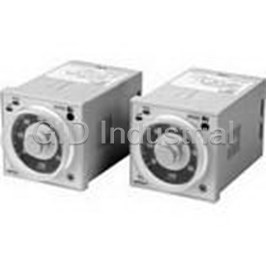
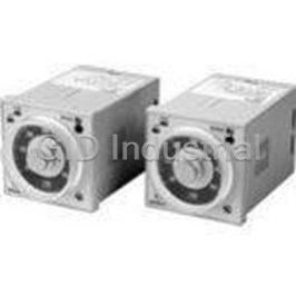
OMRON AUTOMATION H3BA-N8H110VAC
Description
Timer Instrument Relay Output
H3BA-N8H110VAC
Part Number
H3BA-N8H110VAC
Price
Request Quote
Manufacturer
OMRON AUTOMATION
Lead Time
Request Quote
Category
Tools and Supplies » Timer Instrument
Specifications
Manufacturer
Omron Automation
Manufacturers Part #
H3BA-N8H110VAC
Lead Time
4 Week Lead Time
Industry Aliases
H3BA-N8H 110 VAC
Sub-Category
Timer Instruments
Factory Pack Quantity
1
Datasheet

Extracted Text
Solid-state Timer H3BA-N Please read and understand this catalog before purchasing the products. Please consult your OMRON representative if you have any questions or comments. Refer to Warranty and Application Considerations (page 21), and Safety Precautions (page 17). Solid-state Timer with Valuable Multiple-time Ranges and Multiple-operating Modes • Handles a wide range of applications through eight operating modes. With H3BA-N8H models, the output type can be switched between time-limit DPDT and time-limit SPDT + instantaneous SPDT using a selector. Setting rings (order separately) to enable consistent settings and to limit the setting range. Panel Covers (order separately) to enable various panel designs. CE marking. UL, CSA and CCC certification, conforms to LR. ■ Broad Line-up of H3B@-N Series H3B@-N H3BA-N H3BF-N H3BG-N H3BH-N Multi-functional Timer Twin Timer Star-delta Timer Power OFF-delay Timer H3BA-N 11-pin model H3BF-N8 8-pin model H3BG-N8 8-pin model H3BH-N8 8-pin model 8-pin with 8-pin with H3BA-N8H H3BG-N8H instantaneous instantaneous contact output contact output and time-limit output Note: Refer to the H3BF-N/BG-N/BH-N Datasheet (Cat. No. L094-E1-02) for details. Solid-state Timer H3BA-N 1 Model Number Structure ■ Model Number Legend H3BA-N@ 1 1. Number of Pins/Output None: 11-pin models/Time-limit DPDT 8H: 8-pin models/Time-limit SPDT and switchable SPDT (time-limit ↔ instantaneous) Ordering Information ■ List of Models Control output Supply voltage 11-pin models 8-pin models Contact output: DPDT (time-limit output) 110 VAC (50/60 Hz) H3BA-N 110 VAC --- 220 VAC (50/60 Hz) H3BA-N 220 VAC 24 VDC H3BA-N 24 VDC Contact output: Time-limit SPDT and 110 VAC (50/60 Hz) --- H3BA-N8H 110 VAC switchable SPDT 220 VAC (50/60 Hz) H3BA-N8H 220 VAC (time-limit ↔ instantaneous) 24 VDC H3BA-N8H 24 VDC ■ Accessories (Order Separately) Name/specifications Models Flush Mounting Adapters Y92F-30 Y92F-70 Y92F-71 Mounting Tracks 50 cm (l) × 7.3 mm (t) PFP-50N 1 m (l) × 7.3 mm (t) PFP-100N 1 m (l) × 16 mm (t) PFP-100N2 End Plate PFP-M Spacer PFP-S Protective Cover Y92A-48B Track Mounting/ 8-pin P2CF-08 Front Connecting Sockets 11-pin P2CF-11 Back Connecting Sockets 8-pin P3G-08 11-pin P3GA-11 Time Setting Rings Setting a specific time Y92S-27 Limiting the setting range Y92S-28 Panel Covers (See note 1.) Light gray (5Y7/1) Y92P-48GL Black (N1.5) Y92P-48GB Hold-down Clips (See note 2.) For PL08 Socket Y92H-1 For PF085A Socket Y92H-2 Note: 1. The Time Setting Ring and Panel Cover are sold together. 2. Hold-down Clips are sold in sets of two. 2 Solid-state Timer H3BA-N Specifications ■ General Item H3BA-N H3BA-N8H Operating mode A: ON-delay A: ON-delay B: Flicker OFF start H: ON-delay with instantaneous output contact B2: Flicker ON start C: Signal ON/OFF-delay D: Signal OFF-delay E: Interval G: Signal ON/OFF-delay J: One-shot Pin type 11-pin 8-pin Input type No-voltage input --- Output type DPDT (time-limit) SPDT (time-limit) and switchable SPDT (time-limit <---> instantaneous) Mounting method DIN track mounting, surface mounting, and flush mounting Approved standards UL508, CSA C22.2 No.14, LR, CCC Conforms to EN61812-1 (Pollution degree 2 / Overvoltage category ) EMC (EMI) EN61812-1 Radiated Emissions: EN 55011 class A Emission AC Mains: EN 55011 class A (EMS) EN61812-1 ESD Immunity: EN 61000-4-2: 6 kV contact discharge, 8 kV air discharge Radiated Radio-Frequency EN 61000-4-3: 10 V/m (80 MHz to 1 GHz AM modulation) Electromagnetic Field Immunity: 3 V/m (1.4 GHz to 2 GHz AM modulation) 1 V/m (2 GHz to 2.7 GHz AM modulation) 10 V/m (900 MHz Pulse modulation) Conducted disturbances: EN 61000-4-6: 10 V (0.15 MHz to 80 MHz) Burst Immunity: EN 61000-4-4: 2 kV power line 2 kV I/O signal line Surge Immunity: EN 61000-4-5: 2 kV common mode 1 kV differential mode Voltage dips: EN 61000-4-11 Voltage interruptions: EN 61000-4-11 ■ Time Ranges Time unit sec 10 s min 10 m hrs 10 h Full scale setting 1.2 Set time 0.05 to 1.2 1.2 to 12 0.12 to 1.2 1.2 to 12 0.12 to 1.2 1.2 to 12 3 0.3 to 3 3 to 30 0.3 to 3 3 to 30 0.3 to 3 3 to 30 12 1.2 to 12 12 to 120 1.2 to 12 12 to 120 1.2 to 12 12 to 120 30 3 to 30 30 to 300 3 to 30 30 to 300 3 to 30 30 to 300 Solid-state Timer H3BA-N 3 ■ Ratings Item H3BA-N H3BA-N8H Rated supply voltage 110 VAC (50/60 Hz), 220 VAC (50/60 Hz), 24 VDC (See notes 1 and 2) Operating voltage range 85% to 110% of rated supply voltage (See note 3) Power reset Minimum power-opening time: 0.1 s No-voltage input ON impedance: 1 kΩ max. ON residual voltage: 1 V max. OFF impedance: 200 kΩ min. Power consumption 110 VAC: Approx. 4.6 VA (1.5 W) 110 VAC: Approx. 3.6 VA (1.6 W) 220 VAC: Approx. 7.6 VA (1.3 W) 220 VAC: Approx. 7.8 VA (1.9 W) 24 VDC: Approx. 0.6 W 24 VDC: Approx. 0.9 W Control outputs Contact: 5 A at 250 VAC, resistance load (cosφ = 1) Note: 1. DC ripple rate: 20% max. 2. Models other than 24-VDC H3BA-N models cause an inrush current. Pay careful attention when attempting to turn on power to such models with non-contact output from a device such as a sensor. 3. 90% or higher if the Timer is used continuously at a high ambient temperature. ■ Characteristics Item H3BA-N H3BA-N8H Accuracy of operating time ±0.3% FS max. (±0.3%±10 ms in a range of 1.2 s) Setting error ±5% FS ±0.05 s max. Reset time Min. power-opening time: 0.1 s max. Min. pulse-input time: 50 ms Influence of voltage ±0.5% FS max. (±0.5%±10 ms in a range of 1.2 s) Influence of temperature ±2% FS max. (±2%±10 ms in a range of 1.2 s) Insulation resistance 100 MΩ min. (at 500 VDC) Dielectric strength 2,000 VAC, 50/60 Hz for 1 min between current-carrying metal parts and exposed non-current-carrying metal parts 2,000 VAC, 50/60 Hz for 1 min between control output terminals and operating circuit 1,000 VAC, 50/60 Hz for 1 min between contacts not located next to each other (750 VAC for H3BA-N8H) Impulse withstand voltage 1 kV (between power terminals) 2 kV (between current-carrying terminal and exposed non-current-carrying metal parts, 1.5 kV for 24-VDC models) Noise immunity AC models: ±1.5 kV (between power terminals), and ±600 V (between input terminals), square-wave noise by noise simulator (pulse width: 100 ns/1 μs, 1-ns rise) DC models: ±480 V (between power terminals), and ±600 V (between input terminals), square-wave noise by noise simulator (pulse width: 100 ns/1 μs, 1-ns rise) Static immunity Malfunction: 4 kV Destruction: 8 kV Vibration resistance Destruction: 10 to 55 Hz with 0.75-mm single amplitude each in three directions Malfunction: 10 to 55 Hz with 0.5-mm single amplitude each in three directions 2 Shock resistance Destruction: 1,000 m/s (approx. 100G) each in three directions 2 Malfunction: 100 m/s (approx. 10G) each in three directions Ambient temperature Operating: –10°C to 55°C (with no icing) Storage: –25°C to 65°C (with no icing) Ambient humidity Operating: 35% to 85% Life expectancy Mechanical: 10 million operations min. (under no load Mechanical: 10 million operations min. (under no at 1,800 operations/h) load at 1,800 operations/h) Electrical: 100,000 operations min. (5 A at 250 VAC, Electrical: 100,000 operations min. (5 A at 250 resistive load at 1,800 operations/h) VAC, resistive load at 360 operations/h) Case color Light gray (Munsell 5Y7/1) Enclosure ratings IEC: IP40 (panel surface) Weight Approx. 95 g Note: For setting the time-limit of the Timer to a cycle of less than 3 seconds or applying the forced reset, use the H3BA-N in mode D (signal OFF- delay). 4 Solid-state Timer H3BA-N Nomenclature H3BA-N H3BA-N8H Power Indicator (Green): Operating Mode Display Window Power Indicator (Green): Output Type Display Window Lit when Timer operates. Lit when Timer operates. Output Type Selector: Select a type from A and H PW PW MODE A MODE A A: Time-limit DPDT UP UP Operating Mode Selector: (default setting) Output Indicator (Orange): Output Indicator (Orange): 1.5 1.5 Select a mode from H: Time-limit SPDT and Lit when Timer outputs. Lit when Timer outputs. 1 2 1 2 A, B, B2, C, D, E, G, and J. instantaneous SPDT Time Range Selector: 0.5 2.5 0.5 2.5 Select one from Scale Range Display Scale Range Display Time Range Selector: Windows Windows 1.2, 3, 12, and 30. Select one from 3 3 0 0 1.2, 3, 12, and 30. sec sec H3BA H3BA Time Unit Selector Time Unit Selector Select a unit from sec, Select a unit from Time setting knob (set time) Time setting knob (set time) 10 s, min, 10 m, hrs, sec, 10 s, min, 10 m, hrs, and 10 h. and 10 h. Solid-state Timer H3BA-N 5 Operation ■ Block Diagrams H3BA-N Time range/ Operating AC (DC) input unit selectors mode selector Oscillation Power supply Counting Output circuit circuit circuit circuit Indicator Reset input, start input, and gate input Input circuit circuit Power-ON Output-ON indicator indicator H3BA-N8H Output type Time range/ AC (DC) input selector unit selectors Oscillation Power supply Counting Output circuit circuit circuit circuit Indicator circuit Power-ON Output-ON indicator indicator Instantaneous output circuit ■ I/O Functions Inputs Start Starts time-measurement. Reset Interrupts time-measurement and resets time-measurement value. No time-measurement is made and control output is OFF while the reset input is ON. Gate Prohibits time-measurement. Outputs Control output Outputs are turned ON according to designated output mode when preset value is reached. 6 Solid-state Timer H3BA-N ■ Basic Setting ■ Using the Setting Ring Setting of Selector Setting a Specific Time The selectors can be turned clockwise and counterclockwise to Mount the Panel Cover on the Timer, set the desired time with the select the desired time unit, time range, output type (only for H3BA- time setting knob, and place Time Setting Ring A onto the time N8H) or operating mode. setting knob so that the time setting notch of Time Setting Ring A is Each selector has a snap mechanism that secures the selector at a in the center of the reset lock position of the Panel Cover. given position. Set the selector at a position at which it is secured. Do Time setting not set it midway between two securing positions or a malfunction Reset lock position notch could result from improper setting. Operating mode selector/ Output type selector Operating mode/ Output type display window Time setting ring A Panel cover Setting position Time setting notch Groove for screwdriver Selection of Operating Mode with H3BA-N Turn the operating mode selector with a screwdriver until the desired operating mode (A, B, B2, C, D, E, G, or J) appears in the display window located above the selector. Example: To set the time to 10 s. Selection of Output Type with H3BA-N8H Limiting the Setting Range Turn the output type selector with a screwdriver until the desired out- Example: To set a range of 10 and 20 s. put type (A or H) appears in the display window located above the Mount the Panel Cover on the Timer, set the time setting knob to 10 s selector. (the lower limit of the setting range), and place Time Setting Ring C onto the time setting knob so that the stopper of Time Setting Ring C Selection of Time Unit and Time Range is on the right edge of the reset lock position of the Panel cover. Next, set the time setting knob to 20 s (the upper limit of the setting range), The desired time unit (sec, 10 s, min, 10 m, hrs, or 10 h) is displayed place Time Setting Ring B onto the time setting knob so that the in the window below the time setting knob by turning the time unit stopper of Time Setting Ring B is on the left edge of the reset lock selector located at the lower right corner of the front panel. A time position of the Panel Cover. range (1.2, 3, 12, or 30) is selected with the time range selector at the lower left corner of the front panel, and the selected time range Stopper Reset lock position appears (in the window at the lower right part) within the plastic frame of the time setting knob. Time setting Time setting Panel cover ring B ring C Range Operating mode Time range display window selector Time unit selector Time unit display window Setting of Time Use the time setting knob to set the desired time. Solid-state Timer H3BA-N 7 ■ Timing Chart Note: 1. The minimum power-opening time (“Rt”) is 0.1 s and the minimum pulse width is 0.05 s. 2. The letter “t” in the timing charts stands for the set time and “t–a” means that the period is less than the time set. H3BA-N Operating mode Timing chart A: ON-delay t t Power 2 and 10 Basic operation Start 2 and 6 Reset 2 and 7 Power Output relay (NC) 1 and 4 (11 and 8) Start Output relay (NO) 1 t and 3 (11 and 9) and output indicator Output Power indicator B: Flicker OFF start t - a ttt tt Power 2 and 10 Basic operation Start 2 and 6 Reset Power 2 and 7 Output relay (NC) 1 and 4 (11 and 8) Start Output relay (NO) t t t t 1 and 3 (11 and 9) and output indicator Output Power indicator B2: Flicker ON start t - a tt t t t Power 2 and 10 Basic operation Start 2 and 6 Reset Power 2 and 7 Output relay 1 and 4 (11 and 8) Start (NC) Output relay (NO) t t t t (Output indicator) 1 and 3 (11 and 9) Output Power indicator C: Signal ON/OFF-delay t - a t - a t - a t t t t Power 2 and 10 Basic operation Start 2 and 6 Power Reset 2 and 7 Output relay 1 and 4 (11 and 8) Start (NC) t t t t Output relay (NO) (Output indicator) Output 1 and 3 (11 and 9) Power indicator 8 Solid-state Timer H3BA-N Operating mode Timing chart D: Signal OFF-delay t - a t - a t - a t t Power 2 and 10 Start 2 and 6 Reset 2 and 7 Output relay 1 and 4 (11 and 8) (NC) Output relay (NO) (Output indicator) 1 and 3 (11 and 9) Power indicator Basic operation Power Start t Output E: Interval t - a t - a t t t t Power 2 and 10 Start 2 and 6 Reset 2 and 7 Output relay 1 and 4 (11 and 8) (NC) Output relay (NO) (Output indicator) 1 and 3 (11 and 9) Power indicator Basic operation Power Start t Output G: Signal ON/OFF-delay Basic operation Power 2 and 10 Start Power 2 and 6 Reset 2 and 7 Start Output relay (See note) t t t t 1 and 4 (11 and 8) (NC) Output Output relay (NO) (Output indicator) Note: Start input is valid and 1 and 3 (11 and 9) retriggerable while the Timer Power indicator is in operation. J: One-shot output Basic operation Power 2 and 10 Start Power 2 and 6 Reset 2 and 7 Start Output relay (See note) t 1±0.6 s 1 and 4 (11 and 8) (Fixed) (NC) 1±0.6 s 1±0.6 s Output (Fixed) Output relay (NO) (Fixed) (Output indicator) 1 and 3 (11 and 9) Note: Start input is valid and Power indicator retriggerable while the Timer is in operation. (Previous start input will be cancelled.) Solid-state Timer H3BA-N 9 Gate Signal Input in Operating Mode A (ON-delay Operation) t1 t2 ON Power OFF ON Start OFF ON Gate OFF ON Reset OFF ON Output OFF relay Note: The set time is the sum of t and t . 1 2 H3BA-N8H, Output Type: A Type Operating mode Timing chart A: ON-delay Rt Rt t - a t t Power 2 and 7 Output relay (NC) 8 and 5 (1 and 4) Output relay (NO) 8 and 6 (1 and 3) and output indicator Power indicator Basic operation Power t Output H3BA-N8H, Output Type: H Type Operating mode Timing chart H: ON-delay with Rt Rt t - a t t instantaneous output contact Power 2 and 7 Output relay 8 and 5 (NC) Output relay 8 and 6 (NO) (output indicator) Instantaneous 1 and 4 output relay (NC) Instantaneous 1 and 3 output relay (NO) Power indicator Basic operation Power t Output 10 Solid-state Timer H3BA-N PW UP PW UP PW UP Dimensions Note: All units are in millimeters unless otherwise indicated. H3BA-N 15 78 6 63.7 13.6 48 0.7 39 dia. 44.8 × 44.8 48 11 pins H3BA-N8H 15 78 6 63.7 13.6 48 0.7 48 39 dia. 44.8 × 44.8 8 pins Dimensions with Set Ring 16.5 50 50 42 dia. Time setting ring Panel cover Dimensions with Y92F-30 Flush Mounting Adapter Panel Cutout Panel P3G Back Connecting Socket +0.6 0.5 R max. (sold separately) 45 −0 (N) +0.6 45 −0 58 52 42 48 Note: The mounting panel thickness should be 1 to 5 mm. Solid-state Timer H3BA-N 11 PW UP PW UP Dimensions with Y92F-70 Flush Mounting Adapter Panel Cutout Panel Adapter mounting hole Two, 4.5 dia. R0.5 max. 52 to 53 45± 0.15 88 65 to 66 76±0.2 45±0.15 58 Dimensions with Y92F-71 Flush Mounting Adapter Panel Cutout Panel R0.5 max. +0.5 56 45 −0 +0.5 58 68 55 −0 45±0.2 43±0.2 Note: The mounting panel thickness +0.2 50 −0 should be 1 to 3.2 mm. Track Mounting Flush Mounting 15 15 91.4 86.4 H3BA-N H3BA-N + H3BA-N8H H3BA-N8H Adapter 112.2* 109.9 101.3* 99 P3GA-11 P3G-08 Y92F-30 Y92F-30 2.3* P2CF-08 2.3* P2CF-11 Note: These dimensions vary with the kind of DIN track (reference value). 12 Solid-state Timer H3BA-N ■ Accessories (Order Separately) Track Mounting/Front Connecting Socket P2CF-08 Terminal Arrangement/ Eight, 3 4.5 Internal Connections 7.8 M3.5 × 7.5 sems Surface Mounting Holes (Top View) Two, 4.5 dia. or two, M4 70 max. 35.4 Two, 4.5 dia. 40±0.2 holes 4 50 max. 20.3 max. P2CF-11 3 4.5 Eleven, Two, 4.5 dia. or two, M4 7.8 M3.5 × 7.5 sems 40±0.2 70 max. 35.4 Two, 4.5 dia. holes 4 50 max. 31.2 max. Back Connecting Socket Terminal Arrangement/ P3G-08 Internal Connections 27 dia. (Bottom View) 45 17 45 4.9 P3GA-11 27 dia. 45 25.6 4.5 6.2 45 16.3 Mounting Track PFP-100N, PFP-50N PFP-100N2 16 7.3±0.15 4.5 4.5 27 29.2 35±0.3 24 35±0.3 27±0.15 15 25 25 25 25 15 15 25 25 25 25 * 1 1.5 1 10 10 10 10 L L L: Length 1 m PFP-100N 50 cm PFP-50N 1 m PFP-100N2 Solid-state Timer H3BA-N 13 PW UP End Plate Time Setting Ring/Panel Cover There are two types of Panel Covers (Y92P-48GL, Y92P-48GB), all PFP-M of which are available in two colors. Use the most suitable type of 10 Panel Cover with the design of the scaling plate according to the 6.2 1.8 application. When setting a given time for the Timer, use of the Y92S-27 or 1 Y92S-28 Time Setting Ring facilitates the time setting operation and 35.5 35.3 50 minimizes possible setting errors by operators. 1.8 The Time Setting Ring and Panel Cover should be used as a pair. 11.5 1.3 Setting a specific time Time Setting Ring A (Y92S-27) and Panel M4 × 8 10 Cover (Y92P-48GL, -48GB) 4.8 pan head screw Limiting the setting Time Setting Ring B or C (Y92S-28), and range Panel Cover (Y92P-48GL, -48GB) Spacer Y92S-27 Y92S-28 Y92S-28 PFP-S 16 Time Setting A Time Setting B Time Setting C 12 5 34.8 44.3 Y92P-48GL Y92P-48GB Light Gray Black 16.5 Protective Cover Y92A-48B The protective cover protects the front panel, particularly the time setting section, against dust, dirt, and water. It also prevents the set value from being altered due to accidental contact with the time Hold-down Clip setting knob. Y92H-1 Y92H-2 Note: 1. The Y92A-48B Protective Cover is made of a hard plastic For PL08 Socket For PF085A Socket and therefore it must be removed to change the timer set value. 2. The Protective Cover cannot be mounted if the Panel Cov- er (sold separately) is used on the Timer. Y92A-48B 14 Solid-state Timer H3BA-N Installation ■ Terminal Arrangement H3BA-N (Contact Output) (–)(~) Power supply (+)(~) H3BA-N8H (Contact Output) Note: The delayed contacts of conventional timers are shown as follows: The contact symbol of the H3BA-N is ex- pressed as follows because of its multiple op- erating modes: H A The instantaneous contacts of conventional MODE timers are shown as follows: (See note.) Power supply (−)(~) (+)(~) Note: The output contact can be set to either instantaneous or time-limit contact using the output type selector located at the upper right corner of the front panel. Solid-state Timer H3BA-N 15 Reset input Start input Gate input ■ Input Connections The inputs of the H3BA-N are no-voltage (short circuit or open) inputs. No-voltage Inputs No-contact Input Contact Input No-contact Input (Connection to NPN open (Connection to a voltage collector output sensor.) output sensor.) 12 to 24 VDC 12 to 24 VDC (sensor power supply) (sensor power supply) + DC power + DC power − supply − supply Timer Timer Timer Sensor Sensor Start/reset/ Start/reset/ Start/reset/ gate gate gate Input (0 V) Input (0 V) Input (0 V) (No. 2 pin) (No. 2 pin) (No. 2 pin) Operates with transistor ON Operates with transistor ON Operates with relay ON No-voltage Input Signal Levels No-contact 1. Short-circuit level input Transistor ON Residual voltage: 1 V max. Impedance when ON: 1 kΩ max. 2. Open level Transistor OFF Impedance when OFF: 200 kΩ min. Contact Use contacts which can adequately input switch 0.1 mA at 5 V 16 Solid-state Timer H3BA-N Safety Precautions Warning Indications ■ Precautions for Safe Use Indicates a potentially hazardous Please observe the following precautions for safe use of this product. situation which, if not avoided, may CAUTION result in minor or moderate injury or in Environmental Precautions property damage. Supplementary comments on what to Store the Timer within specified ratings. If the Timer has been stored Precautions for at -10°C or lower, let it stand for 3 hours or longer at room do or avoid doing, to use the product Safe Use temperature before turning ON the power supply. safely. Use the Timer within the specified ratings for operating temperature Supplementary comments on what to and humidity. Precautions for do or avoid doing, to prevent failure to Do not operate the Timer in locations subject to sudden or extreme operate, malfunction or undesirable Correct Use changes in temperature, or locations where high humidity may result effect on product performance. in condensation. Meaning of Product Safety Symbols Do not use the Timer in locations subject to excessive dust, corrosive gas, or direct sunlight. Do not use the Timer in locations subject to vibration or shock. Used to warn of the risk of electric shock under Extended use in such locations may result in damage due to stress. specific conditions. Install the Timer well away from any sources of static electricity, such as pipes transporting molding materials, powders, or liquids. Used to warn of the risk of minor injury caused by Usage Precautions high temperatures Install a switch or circuit breaker that allows the operator to immediately turn OFF the power, and label it to clearly indicate its function. Used for general mandatory action precautions for which there is no specified symbol. Pay careful attention to polarity to prevent wrong connections when wiring terminals. Internal elements may be destroyed if a voltage outside the rated Use to indicate prohibition when there is a risk of voltage is applied. minor injury from electrical shock or other source Maintain voltage fluctuations in the power supply within the specified if the product is disassembled. range. The Timer uses a transformerless power supply. Do not touch the input terminals while the supply voltage is being applied, otherwise CAUTION an electric shock may occur. Minor electric shock may occasionally occur. Do not disassemble the product or touch the interior of the Timer. Minor burns may occasionally occur. Do not touch the product while power is being supplied or immediately after power is turned OFF. Minor fires may occasionally occur. Tighten terminal screws to a torque of 1.08 N·m so that they do not become loose. Minor electric shock may occasionally occur during operation. Install the terminal cover. Minor electric shock, fire, or malfunction may occasionally occur. Do not allow metal fragments, lead wire scraps, or chips from processing during installation to fall inside the Timer. Solid-state Timer H3BA-N 17 Operating Time Setting ■ Precautions for Correct Use When setting the operating time, do not turn the setting knob beyond its scale range. For precise time setting, conduct operation tests by Changing the Setting adjusting the setting knob. Do not change the time unit, time range, or operation mode while the The accuracy of the operating time of the Analog Timer is indicated Timer is in operation, otherwise the Timer may malfunction. by the percentage value on the basis of the full-scale time. The absolute fluctuation value will not be improved by changing the time setting. Therefore, when selecting the model, be sure that the Connecting the Operating Power application will be able to use a time setting as close as the full-scale Supply time setting of the Timer. The H3BA-N@ contains a capacitor-drop power circuit. Use a Others sinusoidal power supply with a commercial frequency. Do not use power supplies with a high frequency component (such as inverter When conducting a dielectric test, impulse voltage test, or insulation power supplies) for Timers with 110 or 220-VAC specifications. Using resistance test between the electric circuit and non-current-carrying these power supplies can damage internal circuits. metal parts of the Timer mounted to a control panel, be sure to take If voltages other than the rated voltage is applied, the internal the following steps. These steps will prevent the internal circuitry of components may be damaged. The internal element (varistor) will be the Timer from damage that may be caused if a machine on the damaged if a voltage of higher than 100 VAC is applied to the 24- control panel has an improper dielectric strength or insulation VDC line. resistance. Connect the power supply voltage through a relay or switch in such a 1. Separate the Timer from the circuitry of the control panel by way that the voltage reaches a fixed value immediately or the Timer disconnecting the socket from the Timer or wires. may not be reset or a timer error could result. 2. Short-circuit all terminals of the Timer. If any device with no-contact output, such as a proximity sensor, A DC power supply can be connected if its ripple factor is 20% or photoelectric sensor, or SSR, is directly connected to the Timer, less and the mean voltage is within the rated operating voltage range current leakage from the device may cause Timer malfunction. Be of the Timer. sure to test the device with the Timer before using the device for If the wiring to the terminal 2 (common terminal for both the power actual applications. supply and input signals) is broken, the internal circuit will be Before using the Timer to switch inductive loads, be sure to connect destroyed. a surge absorbing element to the Timer in order to prevent the Timer from malfunction and damage. A diode is an example of a surge absorbing element for DC circuits and a surge absorber is an 5, 6, 7 10 example of a surge absorbing element for AC circuits. G, S, R Do not leave the Timer in time-up condition for a month or longer in Input terminal places with high temperatures, otherwise the internal parts, such as H3BA-N an electrolytic capacitor, of the Timer may be damaged. Use the Timer with an appropriate relay so that the Timer will not be left in Closed time-up condition for a long time. 2 If the Timer is mounted in contact with a mounting surface, the service life of internal parts may be shortened. Provide at least 10 mm between the Timer and the mounting surface to prolong the Input/Output service life of the Timer. When the Timer is reset right after the Timer goes into time-up An appropriate input will be applied to the input signal terminals of condition, be sure to provide the Timer with an appropriate circuit the Timer when one of the input terminals (terminals 5, 6, and 7) and configuration considering the resetting time of the Timer so that a the common terminal (terminal 2) for the input signals are short- sequential error will not result. circuited. Do not attempt to connect any input terminal to any terminal other than the common terminal or to apply voltage across other than the specified input and common terminals or the internal circuits of the Timer may be damaged. 10 (See note 2) Power supply AC or DC H3BA-N 5, 6, 7 G, S, R Input contact Input terminal The Timer uses the constant value read method. Be careful when 2 (see note 1) changing the set value because the output of the Timer will be ON when the set value coincides with the count value. Note: 1. Power supply terminal 2 is a common terminal for the input Be sure that the casing of the Timer is free from organic solvents, signals (G, S, R) to the Timer. Never use terminal 10 as the such as paint thinner and benzene, strong acid, and alkali solvents, common terminal for this purpose, otherwise the internal which will damage the casing. circuit of the Timer may be damaged. 2. Do not connect a relay or any other load between these two Note: It is impossible to connect more than two Timers in parallel. points, otherwise the internal circuit of the Timer may be damaged due to the high-tension voltage applied to the input terminals. 18 Solid-state Timer H3BA-N When using the US08, be sure to use 10.5-dia. max. multi-conductor ■ Mounting cable or 3-dia. max. insulated stranded wire for wiring. When the Y92F-30, Y92F-70 or Y92F-71 Flush Mounting Adapter is used, just insert the Timer into the square panel hole. If the panel Surface Mounting coating is too thick and the hooks do not click, spread open the There is no particular restriction on surface mounting directions, but hooks appropriately to the left and right after inserting the Timer to be sure that the Timer is securely mounted horizontally. the hole. Spread open the hooks to the left and right. P2CF Socket Panel When mounting the Timer vertically with the P2CF Socket, consider the movable hooks and be sure that there is a 20-mm space on each of the upper and lower parts of the Socket. The illustration is an ex ample with the Y92F-70. Duct Hook Spread open the hooks to the left and right. P2CF-08 ■ Dismounting Surface Mounting with P2CF Panel PL Socket 1. Secure the Socket to the panel surface with screws and insert the F-shaped hook into the sockets. 2. Connect the Timer to the Socket and press the tip of each hook Panel Mounting by hand. Loosen the screws of the Flush Mounting Adapter, spread open the hooks, and remove the Mounting Adapter. Panel Mounting When the Y92F-30, Y92F-70, Y92F-71 Mounting Adapter is used, When the Y92F-30 Flush Mounting Adapter is used, insert the Timer press the hook inwards with the thumb and index finger of both into the square hole from the front side of the panel and put on the hands, and press the Timer towards the front side. Flush Mounting Adapter from the rear side of the Timer. Press the Flush Mounting Adapter so that the space between the Flush Mounting Adapter and the panel is reduced as much as possible, and secure the Flush Mounting Adapter with screws. Panel Screw Y92F-30 Solid-state Timer H3BA-N 19 20 Solid-state Timer H3BA-N Read and Understand this Catalog Please read and understand this catalog before purchasing the product. Please consult your OMRON representative if you have any questions or comments. Warranty and Limitations of Liability WARRANTY OMRON's exclusive warranty is that the products are free from defects in materials and workmanship for a period of one year (or other period if specified) from date of sale by OMRON. OMRON MAKES NO WARRANTY OR REPRESENTATION, EXPRESS OR IMPLIED, REGARDING NON-INFRINGEMENT, MERCHANTABILITY, OR FITNESS FOR PARTICULAR PURPOSE OF THE PRODUCTS. ANY BUYER OR USER ACKNOWLEDGES THAT THE BUYER OR USER ALONE HAS DETERMINED THAT THE PRODUCTS WILL SUITABLY MEET THE REQUIREMENTS OF THEIR INTENDED USE. OMRON DISCLAIMS ALL OTHER WARRANTIES, EXPRESS OR IMPLIED. LIMITATIONS OF LIABILITY OMRON SHALL NOT BE RESPONSIBLE FOR SPECIAL, INDIRECT, OR CONSEQUENTIAL DAMAGES, LOSS OF PROFITS OR COMMERCIAL LOSS IN ANY WAY CONNECTED WITH THE PRODUCTS, WHETHER SUCH CLAIM IS BASED ON CONTRACT, WARRANTY, NEGLIGENCE, OR STRICT LIABILITY. In no event shall the responsibility of OMRON for any act exceed the individual price of the product on which liability is asserted. IN NO EVENT SHALL OMRON BE RESPONSIBLE FOR WARRANTY, REPAIR, OR OTHER CLAIMS REGARDING THE PRODUCTS UNLESS OMRON'S ANALYSIS CONFIRMS THAT THE PRODUCTS WERE PROPERLY HANDLED, STORED, INSTALLED, AND MAINTAINED AND NOT SUBJECT TO CONTAMINATION, ABUSE, MISUSE, OR INAPPROPRIATE MODIFICATION OR REPAIR. Application Considerations SUITABILITY FOR USE OMRON shall not be responsible for conformity with any standards, codes, or regulations that apply to the combination of the product in the customer's application or use of the product. Take all necessary steps to determine the suitability of the product for the systems, machines, and equipment with which it will be used. Know and observe all prohibitions of use applicable to this product. NEVER USE THE PRODUCT FOR AN APPLICATION INVOLVING SERIOUS RISK TO LIFE OR PROPERTY WITHOUT ENSURING THAT THE SYSTEM AS A WHOLE HAS BEEN DESIGNED TO ADDRESS THE RISKS, AND THAT THE OMRON PRODUCT IS PROPERLY RATED AND INSTALLED FOR THE INTENDED USE WITHIN THE OVERALL EQUIPMENT OR SYSTEM. PROGRAMMABLE PRODUCTS OMRON shall not be responsible for the user's programming of a programmable product, or any consequence thereof. Disclaimers CHANGE IN SPECIFICATIONS Product specifications and accessories may be changed at any time based on improvements and other reasons. Consult with your OMRON representative at any time to confirm actual specifications of purchased product. DIMENSIONS AND WEIGHTS Dimensions and weights are nominal and are not to be used for manufacturing purposes, even when tolerances are shown. PERFORMANCE DATA Performance data given in this catalog is provided as a guide for the user in determining suitability and does not constitute a warranty. It may represent the result of OMRON's test conditions, and the users must correlate it to actual application requirements. Actual performance is subject to the OMRON Warranty and Limitations of Liability. OMRON Corporation Industrial Automation Company Authorized Distributor: Tokyo, JAPAN Contact: www.ia.omron.com Regional Headquarters OMRON EUROPE B.V. OMRON ELECTRONICS LLC Wegalaan 67-69-2132 JD Hoofddorp One Commerce Drive Schaumburg, The Netherlands IL 60173-5302 U.S.A. Tel: (31)2356-81-300/Fax: (31)2356-81-388 Tel: (1) 847-843-7900/Fax: (1) 847-843-7787 © OMRON Corporation 1997 All Rights Reserved. OMRON ASIA PACIFIC PTE. LTD. OMRON (CHINA) CO., LTD. In the interest of product improvement, No. 438A Alexandra Road # 05-05/08 (Lobby 2), Room 2211, Bank of China Tower, specifications are subject to change without notice. Alexandra Technopark, 200 Yin Cheng Zhong Road, CSM_1_3_0714 Singapore 119967 PuDong New Area, Shanghai, 200120, China Tel: (65) 6835-3011/Fax: (65) 6835-2711 Tel: (86) 21-5037-2222/Fax: (86) 21-5037-2200 Cat. No. L093-E1-03 0313 (1197) (O)
Frequently asked questions
How does Electronics Finder differ from its competitors?

Is there a warranty for the H3BA-N8H110VAC?
Which carrier will Electronics Finder use to ship my parts?
Can I buy parts from Electronics Finder if I am outside the USA?
Which payment methods does Electronics Finder accept?
Why buy from GID?

Quality
We are industry veterans who take pride in our work

Protection
Avoid the dangers of risky trading in the gray market

Access
Our network of suppliers is ready and at your disposal

Savings
Maintain legacy systems to prevent costly downtime

Speed
Time is of the essence, and we are respectful of yours
Related Products
SPDT Timer Instrument 24VAC/12VDC 240VAC/240VDC Relay Output E3A2-10M4
SPDT Timer Instrument 24VAC/12VDC 240VAC/240VDC Relay Output E3A2-10M4D
SPDT Timer Instrument 24VAC/12VDC 240VAC/240VDC Relay Output E3A2-R3M4
SPDT Timer Instrument 24VAC/12VDC 240VAC/240VDC Relay Output E3A2-R3M4T
Mechatronic Analog Timer H3AM-NS-A-300AC100-240
Timer Instrument Relay Output H3BA-N110VAC
Request a Quote

The quote request has been received
Close

Facing challenges or have inquiries? Feel free to contact us!
Call Us +1-469-283-2440
What they say about us
FANTASTIC RESOURCE
One of our top priorities is maintaining our business with precision, and we are constantly looking for affiliates that can help us achieve our goal. With the aid of GID Industrial, our obsolete product management has never been more efficient. They have been a great resource to our company, and have quickly become a go-to supplier on our list!
Bucher Emhart Glass
EXCELLENT SERVICE
With our strict fundamentals and high expectations, we were surprised when we came across GID Industrial and their competitive pricing. When we approached them with our issue, they were incredibly confident in being able to provide us with a seamless solution at the best price for us. GID Industrial quickly understood our needs and provided us with excellent service, as well as fully tested product to ensure what we received would be the right fit for our company.
Fuji
HARD TO FIND A BETTER PROVIDER
Our company provides services to aid in the manufacture of technological products, such as semiconductors and flat panel displays, and often searching for distributors of obsolete product we require can waste time and money. Finding GID Industrial proved to be a great asset to our company, with cost effective solutions and superior knowledge on all of their materials, it’d be hard to find a better provider of obsolete or hard to find products.
Applied Materials
CONSISTENTLY DELIVERS QUALITY SOLUTIONS
Over the years, the equipment used in our company becomes discontinued, but they’re still of great use to us and our customers. Once these products are no longer available through the manufacturer, finding a reliable, quick supplier is a necessity, and luckily for us, GID Industrial has provided the most trustworthy, quality solutions to our obsolete component needs.
Nidec Vamco
TERRIFIC RESOURCE
This company has been a terrific help to us (I work for Trican Well Service) in sourcing the Micron Ram Memory we needed for our Siemens computers. Great service! And great pricing! I know when the product is shipping and when it will arrive, all the way through the ordering process.
Trican Well Service
GO TO SOURCE
When I can't find an obsolete part, I first call GID and they'll come up with my parts every time. Great customer service and follow up as well. Scott emails me from time to time to touch base and see if we're having trouble finding something.....which is often with our 25 yr old equipment.
ConAgra Foods