

 Manufacturers
OMRON AUTOMATION H3DSALCAC24230DC2448

Description
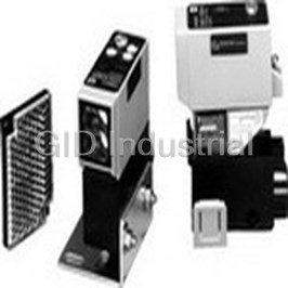
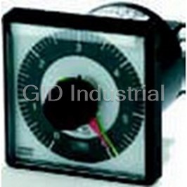
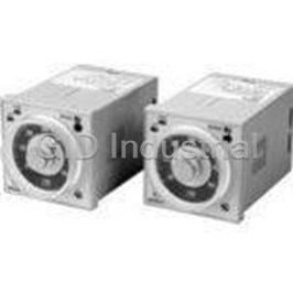
Analog Set Multi-Function Timers
H3DSALCAC24230DC2448
Part Number
H3DSALCAC24230DC2448
Price
Request Quote
Manufacturer
OMRON AUTOMATION
Lead Time
Request Quote
Category
Tools and Supplies » Timer Instrument
Specifications
Manufacturer
Omron Automation
Manufacturers Part #
H3DSALCAC24230DC2448
Lead Time
52 Week Lead Time
Industry Aliases
H3DS-ALC-AC24-230/DC24-48
Sub-Category
Timer Instruments
Factory Pack Quantity
1
Datasheet

Extracted Text
Solid-state Timer H3DS CSM_H3DS_DS_E_5_2 DIN Track Mounted, Standard 17.5-mm Width Timer Range • A wide AC/DC power supply range (24 to 230 VAC/ 24 to 48 VDC) reduces the number of timer models kept in stock. (24 to 230 VAC/VDC with H3DS-XL@) Smart Dial/Selector-locking Mechanism: Prevents the dials and selectors on the Timer’s front panel from being inadvertently op- erated or being operated without authorization. The lock can only be unlocked and locked with an optional pen-type Lock Key. Screw-Less Clamp type available. (H3DS-@LC) Sticker provided for easy timer identification and management. Terminal clamp left open when delivered (screw terminal type). Finger protection terminal block to meet VDE0106/P100. Enables easy sequence checks through instantaneous outputs for a zero set value at any time range. Incorporates environment-friendly, cadmium-free contacts. Conforms to EN61812-1 and IEC60664-1 4 kV/2 for Low Voltage, and EMC Directives. ■ Broad Line-up of H3DS Series H3DS H3DS-M/S/A H3DS-F H3DS-G H3DS-X Standard Timer Twin Timer Star-delta Timer Two-wired Timer H3DS-M (eight multi-modes) H3DS-F H3DS-G H3DS-X H3DS-S (four multi-modes) H3DS-A (single mode) Contents Solid-state Timer H3DS-M/-S/-A........................................................................................... 2 H3DS-F..................................................................................................... 13 H3DS-G.................................................................................................... 20 H3DS-X .................................................................................................... 27 Common to ALL Timers Installation of Screw-Less Clamp Models................................................. 33 Accessories .............................................................................................. 36 Precautions............................................................................................... 37 1 Solid-state Multi-functional Timer H3DS-M/-S/-A Eight operating modes (H3DS-M) and four operating modes (H3DS-S) cover a wide range of applications. A wide time setting range of 0.10 s to 120 h. Two LEDs indicate power and relay status respectively. Model Number Structure ■ Model Number Legend H3DS - L 1 2 3 1. M: Multi-function type S: Standard type A: Single-function type 2. L: Smart lock mechanism 3. None: Screw terminal type C: Screw-Less Clamp type Ordering Information ■ List of Models Supply voltage Control output Input type Operating mode Model (see note) Screw terminal Screw-Less type Clamp type 24 to 230 VAC (50/60Hz)/ Contact output: SPDT Voltage input Eight multi-modes: A, B, H3DS-ML H3DS-MLC 24 to 48 VDC B2, C, D, E, G, J (time-limit output SP- DT) No-input available Four multi-modes: A, B2, H3DS-SL H3DS-SLC E, J Single mode: A H3DS-AL H3DS-ALC Note: The operating modes are as follows: A: ON-delay B: Flicker OFF start B2: Flicker ON start C: Signal ON/OFF-delay D: SIgnal OFF-delay E: Interval G: Signal ON/OFF-delay J: One shot 2 H3DS-M/-S/-A ■ Accessories (Order Separately) Lock Key Y92S-38 Mounting Track 50 cm (l) x 7.3 mm (t) PFP-50N 1 m (l) x 7.3 mm (t) PFP-100N 1 m (l) x 16 mm (t) PFP-100N2 End Plate PFP-M Spacer PEP-S 3 H3DS-M/-S/-A Specifications ■ General Item H3DS-ML@ H3DS-SL@ H3DS-AL@ Operating mode A: ON-delay (Signal or Power) A: ON-delay A: ON-delay (fixed) B: Flicker OFF start (Signal or Power) B2: Flicker ON start B2: Flicker ON start (Signal or Power) E: Interval C: Signal ON/OFF-delay J: One-shot D: Signal OFF-delay E: Interval (Signal or Power) G: Signal ON/OFF-delay J: One-shot (Signal or Power) Input type Voltage input --- Output type Relay: SPDT External connections Screw terminal, Screw-Less Clamp 2 Terminal block Screw terminal type: Clamps two 2.5-mm max. bar terminals without sleeves. 2 Screw-Less Clamp type: Clamps two 1.5-mm max. bar terminals without sleeves. Terminal screw 0.98 N·m max. tightening torque Mounting method DIN track mounting (see note) Attachment Nameplate label Approved standards UL508, CSA C22.2 No.14 Conforms to EN61812-1, IEC60664-1 4 kV/2, VDE0106/P100 Output category according to IEC60947-5-1 (AC-13; 250 V 5 A/AC-14; 250 V 1 A/AC-15; 250 V 1 A/DC-13; 30 V 0.1 A/ DC-14; 30 V 0.05 A) Note: Can be mounted to 35-mm DIN Track with a plate thickness of 1 to 2.5 mm. ■ Time Ranges Time scale display Time range 0.1 s 0.1 to 1.2 s 1 s 1 to 12 s 0.1 m 0.1 to 1.2 min 1 m 1 to 12 min 0.1 h 0.1 to 1.2 h 1 h 1 to 12 h 10 h 10 to 120 h Note: When the time setting dial is set to “0” for any time scale, the output will operate instantaneously. ■ Ratings Rated supply voltage 24 to 230 VAC (50/60 Hz)/24 to 48 VDC (see notes 1 and 2) Operating voltage range 85% to 110% of rated supply voltage Power reset Minimum power-off time: 0.1 s Reset voltage 2.4 VAC/DC max. Power consumption (see note 3) AC: 32 VA max./3.0 W max. (typical: 30 VA/2.7 W) at 230 VAC DC: 0.7 W max. (typical: 0.6 W) at 24 VDC 1.4 W max. (typical: 1.3 W) at 48 VDC Voltage input Max. permissible capacitance between inputs lines (terminals B1 and A2): 2,000 pF Load connectable in parallel with inputs (terminals B1 and A1). H-level: 20.4 to 253 VAC/20.4 to 52.8 VDC L-level: 0 to 2.4 VAC/DC Control output Contact output: 5 A at 250 VAC with resistive load (cosφ = 1) 1 A at 250 VAC with inductive load (cosφ = 0.3) 5 A at 30 VDC with resistive load (cosφ = 1) 0.15 A max. at 125 VDC with resistive load, 0.1 A max. at 125 VDC with L/R of 7 ms. The minimum applicable load is 10 mA at 5 VDC (P reference value). Contact materials : Ag-alloy Ambient temperature Operating: –10°C to 55°C (with no icing) Storage: –25°C to 65°C (with no icing) Ambient humidity Operating: 35% to 85% Note: 1. DC ripple rate: 20% max. 2. Since an inrush current of 0.5 A will occur when using the power supply voltage at 24 VDC, pay careful attention when turning on or off the power supply to the Timer with a solid-state output such as a sensor. 3. The power consumption is for mode A after the Timer counts the time-up time and for the AC input at 50 Hz. The power consumption of the H3DS-ML includes the input circuit with the B1 and A1 terminals short-circuited. 4 H3DS-M/-S/-A ■ Characteristics Accuracy of operating time ±1% max. of FS (±1% ±10 ms max. at 1.2-s range) Setting error ±10% ±50 ms max. of FS Signal input time 50 ms min. Influence of voltage ±0.7% max. of FS (±0.7% ±10 ms max. at 1.2-s range) Influence of temperature ±5% max. of FS (±5%±10 ms max. at 1.2-s range) Insulation resistance 100 MΩ min. at 500 VDC Dielectric strength Between current-carrying metal parts and exposed non-current-carrying metal parts: 2,000 VAC for 1 min. Between control output terminals and operating circuit: 2,000 VAC for 1 min. Between contacts not located next to each other: 1,000 VAC for 1 min. Vibration resistance Malfunction: 0.5-mm single amplitude at 10 to 55 Hz Destruction: 0.75-mm single amplitude at 10 to 55 Hz 2 Shock resistance Malfunction: 100 m/s 3 times each in 6 directions 2 Destruction: 1,000 m/s 3 times each in 6 directions Impulse withstand voltage 5 kV (between power terminals) 5 kV (between current-carrying metal parts and exposed non-current-carrying metal parts) Noise immunity Square-wave noise generated by noise simulator (pulse width: 100 ns/1 μs, 1-ns rise) ±1.5 kV Static immunity Malfunction: 4 kV Destruction: 8 kV Life expectancy Mechanical: 10 million operations min. (under no load at 1,800 operations/h) Electrical: 100,000 operations min. (5 A at 250 VAC, resistive load at 360 operations/h) (see note) EMC (EMI) EN61812-1 Emission Enclosure: EN55011 Group 1 class B Emission AC Mains: EN55011 Group 1 class B Harmonic Current: EN61000-3-2 Voltage Fluctuation and Flickering: EN61000-3-3 (EMS) EN61812-1 Immunity ESD: IEC61000-4-2 Immunity RF-interference: IEC61000-4-3 Immunity Burst: IEC61000-4-4 Immunity Surge: IEC61000-4-5 Immunity Conducted Disturbance: IEC61000-4-6 Immunity Voltage Dip/Interruption: IEC61000-4-11 Case color Light gray (5Y7/1) Degree of protection IP30 (Terminal block: IP20) Weight Approx. 70 g Note: For reference: In both cases, a life of 100,000 operations can be expected. 5 H3DS-M/-S/-A Connections ■ Block Diagram H3DS-ML@ Zero setting Time scale/ Operating AC (DC) input detection unit selectors mode selector circuit Power supply Oscillation Counting Output circuit circuit circuit circuit Indicator Start input Input circuit circuit Power-ON Output indicator indicator H3DS-SL@/-AL@ Zero setting Time scale/ Operating AC (DC) input detection unit selectors mode selector circuit Power supply Oscillation Counting Output circuit circuit circuit circuit Indicator circuit Power-ON Output indicator indicator ■ I/O Functions Item H3DS-ML@ H3DS-SL@/-AL@ Input Start Starts operation. No input is available. Output Control output Outputs are turned ON according to designated out- Outputs are turned ON according to designated out- put mode when preset value is reached. put mode when preset value is reached. 6 H3DS-M/-S/-A ■ Terminal Arrangement H3DS-MLC H3DS-ML H3DS-SLC/-ALC H3DS-SL/-AL A1 15 B1 A1 15 A1 15 B1 A1 15 L 15 15 15 15 18 16 18 16 18 16 18 16 18 16 A2 18 16 A2 18 16 A2 18 16 A2 (see note 1) (see note 1) (DIN notation) (DIN notation) Note: 1. DC supply voltage does not require the designation of polarity. 2. The contact symbol for the H3DS is indicated with because it offers multiple operating modes and is different from the delayed contact for conventional timers. ■ Input Connections The inputs of the H3DS-ML@ are voltage (voltage imposition or open) inputs. Contact Input No-contact Input No-contact Input (Connection to PNP output sensor.) (Connection to NPN output sensor.) Sensor Timer (+) A2 24 VDC Timer Timer (−) A1 B1 A1 A1 (+) B1 B1 Start Start 24 VDC (−) A2 A2 Operates with PNP transistor ON Sensor Operates with relay ON Operates with NPN transistor ON Voltage Input Signal Levels 1. Transistor ON Residual voltage: 1 V max. (Voltage between terminals B1 and A2 must be more than the rated "H-level" voltage (20.4 VDC min.).) No-contact input 2. Transistor OFF Leakage current: 0.01 mA max. (Voltage between terminals B1 and A2 must be less than the rated "L-level" voltage (2.4 VDC max.).) Use contacts that can adequately switch 0.1 mA at each voltage to be imposed. (When the contacts are Contact ON or OFF, voltage between terminals B1 and A2 must be within the following ranges: input When contacts are ON: 20.4 to 253 VAC/20.4 to 52.8 VDC When contacts are OFF: 0 to 2.4 VAC/DC 7 H3DS-M/-S/-A Operation ■ Basic Operation Setting of Selector Locking/Unlocking of Selectors and Time Setting Dial The selectors can be turned clockwise and counterclockwise to select the desired time scale, or operating mode. The time setting dial, time scale selector, and operating mode selec- Each selector has a snap mechanism that secures the selector at a tor can be locked using the Y92S-38 Lock Key, a special pen type given position. Set the selector at a position at which it is secured. Do tool that is sold separately. To lock the dial or selectors, insert the not set it midway between two securing positions or a malfunction Lock Key in the keyhole to the lower right of the dial or selector and could result from improper setting. turn it clockwise until the dial or selector is completely covered with the red cover. To unlock, turn the Lock Key in the opposite direction. Selection of Operating Mode (except for H3DS-AL) The H3DS-ML/-SL can be set to any one of the operating modes A to J. Turn the operating mode selector with a screwdriver until the desired operating mode appears in the operating mode display win- dow. H3DS-ML (8 modes): A, B, B2, C, D, E, G, J (In order of appearance) H3DS-SL (4 modes): A, E, B2, J, E, E, J, J (In order of appearance) Note: Letters that appear more than once indicate exactly the same Key hole operating mode. Selection of Time Scale The time scale is selected by turning the time scale selector. The time scales will appear in the following order in the time scale display window on the left of the selector: 1 s, 0.1 s, 1 h, 0.1 h, 10 h, 1 h, 1 m, 0.1 m. Note: The time scale “1h” appears twice. Both instances indicate ex- actly the same time scale. Time scale display window and selector Operating mode display window and selector 8 H3DS-M/-S/-A ■ Timing Chart Note: 1. The minimum power reset time is 0.1 s and the minimum signal input time is 0.05 s. 2. The letter “t” in the timing charts stands for the set time and “t–a” means that the period is less than the time set. 3. There is no start input for H3DS-SL@/-AL@ models. Operation starts at power-on. Operating Timing chart mode A: ON-delay t t–a t Basic operation Power (A and A ) 1 2 Power Start (B and A ) 1 2 (see note) ** * Start Output relay: NC t 15 and 16 Output Output relay: NO * For power-on operation, impose voltage to the (output indicator) Start input. The Timer starts operating at the 15 and 18 moment the power is turned on. ** Start input is invalid while the Timer is in operation. Power indicator B: t t t–a tt t t–a Flicker OFF start Basic operation Power (A and A ) 1 2 Power Start (B and A ) 1 2 ** (see note) * Start Output relay: NC tt t t 15 and 16 Output Output relay: NO (output indicator) * For power-on operation, impose voltage to the 15 and 18 Start input. The Timer starts operating at the moment the power is turned on. ** Start input is invalid while the Timer is in operation. Power indicator B2: tt t–a t tt t–a Flicker ON start Power (A and A ) 1 2 Basic operation Start (B and A ) 1 2 Power (see note) ** * Start Output relay: NC 15 and 16 t tt t Output Output relay: NO (output indicator) * For power-on operation, impose voltage to the 15 and 18 Start input. The Timer starts operating at the moment the power is turned on. ** Start input is invalid while the Timer is in Power indicator operation. C: tt t t–at t–a Signal ON/OFF- Power (A and A ) 1 2 delay Start (B and A ) 1 2 Basic operation (see note) Power Output relay: NC 15 and 16 * Start Output relay: NO tt t t (output indicator) 15 and 18 Output * Start input is invalid while the Timer is in Power indicator operation. Note: The start input of the H3DS-ML@ model is activated by applying a voltage to B1 and A2 terminals. The voltage can be applied by turning on the contact between B1 and A1 (Refer to Terminal Arrangement). 9 H3DS-M/-S/-A Operating Timing chart mode D: tt t–a t–a t–a Signal OFF-delay Power (A and A ) 1 2 Basic operation Start (B and A ) 1 2 (see note) Power Output relay: NC * 15 and 16 Start t Output relay: NO (output indicator) Output 15 and 18 * Start input is valid and re-triggerable while the Timer is in operation. Power indicator E: Interval tt t–a t–at Basic operation Power (A and A ) 1 2 Power ** Start (B and A ) 1 2 * (see note) Start t Output relay: NC 15 and 16 Output Output relay: NO * For power-on operation, impose voltage to the (output indicator) Start input. The Timer starts operating at the 15 and 18 moment the power is turned on. ** Start input is valid and re-triggerable while the Timer is in operation. Power indicator G: Basic operation t t t–a t–a t t t t–a Signal ON/OFF- Power (A and A ) 1 2 Power delay Start (B and A ) 1 2 * (see note) Start Output relay: NC t t t t 15 and 16 Output relay: NO Output (output indicator) 15 and 18 * Start input is valid and re-triggerable while the Timer is in operation. Power indicator J: Basic operation t t t–a t–a t One-shot out- put Power (A and A ) 1 2 Power (ON delay) Start (B and A ) 1 2 ** (see note) * Start Output relay: NC 15 and 16 t Approx. Approx. Approx. Approx. 1±0.6 s Output (fixed) 1±0.6 s 1±0.6 s 1±0.6 s Output relay: NO (fixed) (fixed) (fixed) (output indicator) * For power-on operation, impose voltage to the 15 and 18 Start input. The Timer starts operating at the moment the power is turned on. Power indicator ** Start input is valid and re-triggerable while the Timer is in operation. Note: The start input of the H3DS-ML@ model is activated by applying a voltage to B1 and A2 terminals. The voltage can be applied by turning on the contact between B1 and A1 (Refer to Terminal Arrangement). 10 H3DS-M/-S/-A Nomenclature H3DS-ML@/-SL@ H3DS-MLC/-SLC Wire connection holes Output indicator (orange) (Lit while Timer output is ON.) Time setting dial (set time) Set time window Lock for time setting dial Time scale display window and selector (select one from 1 s, Lock for time scale selector Release holes 0.1 s, 1 h, 0.1 h, 10 h, 1 h, 1 m, and 0.1 m) Lock for operating mode selector Operating mode display window and selector (select the mode from A, B, B2, C, D, E, G, and J for the Power-ON indicator (green) H3DS-ML, from A, B2, E, and J for 18 16 A2 (Lit while the power is ON.) the H3DS-SL) Wire connection holes (Front View) (Front View) H3DS-AL@ H3DS-ALC Wire connection holes Output indicator (orange) (Lit while Timer output is ON.) Set time window Time setting dial (set time) Lock for time setting dial Time scale display window and selector (select one from 1 s, Release holes Lock for time scale selector 0.1 s, 1 h, 0.1 h, 10 h, 1 h, 1 m, and 0.1 m) Power-ON indicator (green) 18 16 A2 (Lit while the power is ON.) Wire connection holes (Front View) (Front View) Attach the enclosed label here as a nameplate. (The label is attached to the Timer's DIN Track hook section at the time of shipment.) 11 H3DS-M/-S/-A Dimensions Note: All units are in millimeters unless otherwise indicated. H3DS-ML/-SL/-AL Surface color: Light gray 5Y7/1 (OMRON) 17.5 74 45 80 44 68 H3DS-MLC/-SLC/-ALC 17.5 74 45 80 44 68 ALL DIMENSIONS SHOWN ARE IN MILLIMETERS. To convert millimeters into inches, multiply by 0.03937. To convert grams into ounces, multiply by 0.03527. In the interest of product improvement, specifications are subject to change without notice. 12 Solid-state Twin Timer H3DS-F Operates in flicker-OFF or f licker-ON start mode with one Unit. Independent ON- and OFF-time settings. Combinations of long ON- or OFF-time and short OFF- or ON- time setting are possible. Long time range from 0.1 s to 12 h for both ON and OFF time settings. For the most recent information on models that have been certified for safety standards, refer to your OMRON website. Model Number Structure ■ Model Number Legend H3DS -F L 123 1. F: Twin timers 2. L: Smart lock mechanism 3. None: Screw terminal type C: Screw-Less Clamp type Ordering Information ■ List of Models Operating mode Supply voltage Model Screw terminal type Screw-Less Clamp type Flicker-OFF/Flicker-ON start 24 to 230 VAC (50/60 Hz)/24 to 48 VDC H3DS-FL H3DS-FLC ■ Accessories (Order Separately) Lock Key Y92S-38 Mounting Track 50 cm (l) x 7.3 mm (t) PFP-50N 1 m (l) x 7.3 mm (t) PFP-100N 1 m (l) x 16 mm (t) PFP-100N2 End Plate PFP-M Spacer PEP-S 13 H3DS-F Specifications ■ General Item H3DS-F Operating mode Flicker-OFF/Flicker-ON start Output type Relay: SPDT External connections Screw terminal, Screw-Less Clamp 2 Terminal block Screw terminal type: Clamps two 2.5-mm max. bar terminals without sleeves. 2 Screw-Less Clamp type: Clamps two 1.5-mm max. bar terminals without sleeves. Terminal screw tightening torque 0.98 N·m max. Mounting method DIN track mounting (see note) Attachment Nameplate label Approved standards UL508, CSA C22.2 No.14 Conforms to EN61812-1, IEC60664-1 4 kV/2, VDE0106/P 100 Output category according to IEC60947-5-1 (AC-13; 250 V 5A/AC-15; 250 V 1 A/DC-13; 30 V 0.1 A) Note: Can be mounted to 35-mm DIN Track with a plate thickness of 1 to 2.5 mm. ■ Time Ranges Time scale display Time range 0.1 s 0.1 to 1.2 s 1 s 1 to 12 s 0.1 m 0.1 to 1.2 min 1 m 1 to 12 min 0.1 h 0.1 to 1.2 h 1 h 1 to 12 h Note: When the time setting dial is set to “0” for any time scale, the output will operate instantaneously. ■ Ratings Rated supply voltage (See note.) 24 to 230 VAC (50/60 Hz)/24 to 48 VDC Operating voltage range 85% to 110% of rated supply voltage Power reset Minimum power-off time: 0.1 s Reset voltage 2.4 VAC/DC max. Power consumption AC: 33 VA max./2.2 W max. (typical: 31 VA/2.0 W) at 230 VAC DC: 0.7 W max. (typical: 0.6 W) at 24 VDC 1.4 W max. (typical: 1.2 W) at 48 VDC Voltage input Max. permissible capacitance between inputs lines (terminals B1 and A2): 2,000 pF Load connectable in parallel with inputs (terminals B1 and A1). H-level: 20.4 to 253 VAC/20.4 to 52.8 VDC L-level: 0 to 2.4 VAC/DC Control output Contact output: 5 A at 250 VAC with resistive load (cosφ = 1) 1 A at 250 VAC with inductive load (cosφ = 0.3) 5 A at 30 VDC with resistive load (cosφ = 1) Ambient temperature Operating: –10°C to 55°C (with no icing) Storage: –25°C to 65°C (with no icing) Ambient humidity Operating: 35% to 85% Note: DC ripple rate: 20% max. 14 H3DS-F ■ Characteristics Accuracy of operating time ±1% max. of FS (±1% ±10 ms max. at 1.2-s range) Setting error ±10% ± 50 ms max. of FS Influence of voltage ±0.5% max. of FS (±0.5% ±10 ms max. at 1.2-s range) Influence of temperature ±5% max. of FS (±5% ± 10 ms max. at 1.2-s range) Insulation resistance 100 MΩ min. at 500 VDC Dielectric strength Between current-carrying metal parts and exposed non-current-carrying metal parts: 2,000 VAC (50/60 Hz) for 1 min. Between control output terminals and operating circuit: 2,000 VAC (50/60 Hz) for 1 min. Between contacts not located next to each other: 1,000 VAC (50/60 Hz) for 1 min. Impulse withstand voltage 3 kV (between power supply terminals) 4.5 kV (between current-carrying metal parts and exposed non-current-carrying metal parts) Noise immunity Square-wave noise generated by noise simulator (pulse width: 100 ns/1 μs, 1-ns rise) ±1.5 kV Static immunity Malfunction: 4 kV Destruction: 8 kV Vibration resistance Malfunction: 0.5-mm single amplitude at 10 to 55 Hz Destruction: 0.75-mm single amplitude at 10 to 55 Hz 2 Shock resistance Malfunction: 200 m/s , 3 times each in 6 directions 2 Destruction: 300 m/s , 3 times each in 6 directions Life expectancy Mechanical: 10 million operations min. (under no load at 1,800 operations/h) Electrical: 100,000 operations min. (5 A at 250 VAC, resistive load at 360 operations/h) (see note) EMC (EMI) EN61812-1 Emission Enclosure: EN55011 Group 1 class B Emission AC Mains: EN55011 Group 1 class B Harmonic Current: EN61000-3-2 Voltage Fluctuation and Flickering: EN61000-3-3 (EMS) EN61812-1 Immunity ESD: EN61000-4-2: 6 kV contact discharge (level 3) 8 kV air discharge (level 3) Immunity RF-interference from AM Radio Waves: EN61000-4-3: 10 V/m (80 MHz to 1 GHz) (level 3) Immunity Burst: EN61000-4-4: 2 kV power port and output port (level 3) 1 kV control port with capacitive clamp (level 3) Immunity Surge: EN61000-4-5: 2 kV common mode (level 3) 1 kV differential mode (level 3) Case color Light gray (5Y7/1) Degree of protection IP30 (IP20 for terminal block) Weight Approx. 70 g Note: For reference: A maximum current of 0.15 A can be switched at 125 VDC (cosφ=1). A maximum current of 0.1 A can be switched if L/R is 7 ms. In both cases, a life of 100,000 operations can be expected. The minimum applicable load is 10 mA at 5 VDC (failure level: P). 15 H3DS-F Connections ■ Block Diagram ON OFF indicator indicator (Orange) (Green) ON/OFF start selector AC (DC) Indicator Time scale input circuit selector ROM RAM Clock One-chip microcomputer Power Output supply circuit circuit ■ I/O Function Inputs Flicker-ON start operation begins when inputs are turned ON. Outputs Control output Outputs are turned ON/OFF according to the time set by the ON-and OFF-time setting dial. ■ Terminal Arrangement H3DS-FLC H3DS-FL A1 15 B1 A1 15 B1 L 15 15 18 16 18 16 18 16 A2 18 16 A2 (See note 2.) Note: 1. If voltage is applied to terminal B1, or if terminals A1 and B1 are shorted, the operating mode is switched to flicker-ON start mode. If these terminals are disconnected, the mode switches to flicker-OFF start mode. 2. DC supply voltage does not require the designation of polarity. 16 H3DS-F Operation ■ Basic Operation Setting of Selector Time Setting The selectors can be turned clockwise and counterclockwise to Use the ON/OFF-time setting dials to set the ON/OFF time. select the desired time scale, or operating mode. Each selector has a snap mechanism that secures the selector at a Locking/Unlocking of Selectors and given position. Set the selector at a position at which it is secured. Do not set it midway between two securing positions or a malfunction Time Setting Dial could result from improper setting. The ON/OFF-time setting dials and time scale selectors can be locked using the Y92S-38 Lock Key, a special pen type tool that is Settings for ON/OFF Start sold separately. To lock the dials or selectors, insert the Lock Key in the keyhole to the lower right of the dial or selector and turn it clock- If voltage is applied to terminal B1, or if terminals A1 and B1 are wise until the dial or selector is completely covered with the red shorted, the operating mode is switched to flicker-ON start mode. If cover. To unlock, turn the Lock Key in the opposite direction. these terminals are disconnected, the mode switches to flicker-OFF start mode. The operating mode will not change if the state of the applied voltage changes during timer operation. Selection of Time Scale The time scale is selected by turning the ON-time scale selector and OFF-time scale selector. The time scales will appear in the following order in each time scale display window on the left of the selector: 0.1 s, 1 h, 0.1 h, 1 m, 1 s, 0.1 h, 0.1 m, 1 s. Note: The time scales “1 s” and “0.1 h” appear twice. Both instances indicate exactly the same time scale. Key hole ON-time scale display window and selector OFF-time scale display window and selector ■ Timing Charts Operating Timing chart mode Flicker-OFF 0.1 s min. start ON Power (A and A ) 1 2 OFF (See note 1.) Output relay: NO ON 15 and 18 OFF (ON indicator) ON Output relay: NC OFF 15 and 16 t : ON set time ON ON t : OFF set time OFF indicator OFF OFF 0.1 s min. Flicker-ON start ON Power (A and A ) 1 2 OFF (See note 1.) ON Signal (B and A ) 1 2 OFF Output relay: NO ON 15 and 18 OFF (ON indicator) ON Output relay: NC OFF 15 and 16 t : ON set time ON ON t : OFF set time OFF OFF indicator OFF Note: 1. If voltage is applied to terminal B1, or if terminals A1 and B1 are shorted, the operating mode is switched to flicker-ON start mode. If these terminals are disconnected, the mode switches to flicker-OFF start mode. 2. The reset time requires a minimum of 0.1 s. 3. When power is supplied in flicker-ON start mode, the OFF indicator lights momentarily. This, however, has no effect on the performance of the Timer. 17 H3DS-F Nomenclature H3DS-FL@ H3DS-FLC Wire connection holes Output ON/OFF indicator When the output is ON: Orange When the output is OFF: Green ON-time setting dial ON-time display window Lock for ON-time setting dial ON-time scale display window and selector (select one from Lock for ON-time scale selector 0.1 s, 1 s, 0.1 m, 1 m, 0.1 h, and 1 h) Release holes OFF-time setting dial OFF-time display window Lock for OFF-time setting dial OFF-time scale display window and selector (select one from Lock for OFF-time scale selector 0.1 s, 1 s, 0.1 m, 1 m, 0.1 h, and 1 h) 18 16 A2 Wire connection holes (Front View) (Front View) Attach the enclosed label here as a nameplate. (The label is attached to the Timer's DIN Track hook section at the time of shipment.) 18 H3DS-F Dimensions H3DS-FL Surface color: Light gray 5Y7/1 (OMRON) 17.5 74 45 80 44 68 H3DS-FLC Surface color: Light gray 5Y7/1 (OMRON) 17.5 74 45 80 44 68 ALL DIMENSIONS SHOWN ARE IN MILLIMETERS. To convert millimeters into inches, multiply by 0.03937. To convert grams into ounces, multiply by 0.03527. In the interest of product improvement, specifications are subject to change without notice. 19 Solid-state Star-delta Timer H3DS-G A wide star-time range (up to 120 seconds) and star-delta trans- fer time range (up to 1 second) For the most recent information on models that have been certified for safety standards, refer to your OMRON website. Model Number Structure ■ Model Number Legend H3DS -G L 1 2 3 1. G: Star-delta timer 2. L: Smart lock mechanism 3. None: Screw terminal type C: Screw-Less Clamp type Ordering Information ■ List of Models Operating mode Supply voltage Model Screw terminal type Screw-Less Clamp type Star-delta operation 24 to 230 VAC (50/60 Hz)/24 to 48 VDC H3DS-GL H3DS-GLC ■ Accessories (Order Separately) Lock Key Y92S-38 Mounting Track 50 cm (l) x 7.3 mm (t) PFP-50N 1 m (l) x 7.3 mm (t) PFP-100N 1 m (l) x 16 mm (t) PFP-100N2 End Plate PFP-M Spacer PEP-S 20 H3DS-G Specifications ■ General Item H3DS-G Operating mode Star-delta operation Operating/Reset method Time-limit operation/Self-reset External connections Screw terminal, Screw-Less Clamp 2 Terminal block Screw terminal type: Clamps two 2.5-mm max. bar terminals without sleeves. 2 Screw-Less Clamp type: Clamps two 1.5-mm max. bar terminals without sleeves. Terminal screw tightening torque 0.98 N·m max. Output type (Star operation circuit) Relay: SPST-NO (Delta operation circuit) Relay: SPST-NO Mounting method DIN track mounting (see note) Attachment Nameplate label Approved standards UL508, CSA C22.2 No.14 Conforms to EN61812-1, IEC60664-1 4 kV/2, VDE0106/P100 Output category according to IEC60947-5-1 (AC-13; 250 V 5A/AC-15; 250 V 1 A/DC-13; 30 V 0.1 A) Note: Can be mounted to 35-mm DIN Track with a plate thickness of 1 to 2.5 mm. ■ Time Ranges Time scale Star operation time ranges x 1 1 to 12 s x 10 10 to 120 s Star-delta transfer time Programmable at 0.05 s, 0.1 s, 0.5 s, or 1 s ■ Ratings Rated supply voltage (see note) 24 to 230 VAC (50/60 Hz)/24 to 48 VDC Operating voltage range 85% to 110% of rated supply voltage Power reset Minimum power-off time: 0.5 s Reset voltage 2.4 VAC/DC max. Power consumption AC: 21 VA max./1.7 W max. (typical: 20 VA/1.6 W) at 230 VAC DC: 1.3 W max. (typical: 1.2 W) at 24 VDC 0.7 W max. (typical: 0.6 W) at 48 VDC Control output Contact output: 5 A at 250 VAC with resistive load (cosφ = 1) 1 A at 250 VAC with inductive load (cosφ = 0.3) 5 A at 30 VDC with resistive load (cosφ = 1) Ambient temperature Operating: –10°C to 55°C (with no icing) Storage: –25°C to 65°C (with no icing) Ambient humidity Operating: 35% to 85% Note: DC ripple rate: 20% max. 21 H3DS-G ■ Characteristics Accuracy of operating time ±1% max. of FS Setting error ±10% ± 50 ms max. of FS Total tolerance of transfer ± (25% FS + 5 ms) max. time Influence of voltage ±0.5% max. of FS Influence of temperature ±5% max. of FS Insulation resistance 100 MΩ min. at 500 VDC Dielectric strength Between current-carrying metal parts and exposed non-current-carrying metal parts: 2,000 VAC (50/60 Hz) for 1 min. Between control output terminals and operating circuit: 2,000 VAC (50/60 Hz) for 1 min. Between contacts not located next to each other: 1,000 VAC (50/60 Hz) for 1 min. Impulse withstand voltage 3 kV (between power supply terminals) 4.5 kV (between current-carrying metal parts and exposed non-current-carrying metal parts) Noise immunity Square-wave noise generated by noise simulator (pulse width: 100 ns/1 μs, 1-ns rise) ±1.5 kV Static immunity Malfunction: 4 kV Destruction: 8 kV Vibration resistance Malfunction: 0.5-mm single amplitude at 10 to 55 Hz Destruction: 0.75-mm single amplitude at 10 to 55 Hz 2 Shock resistance Malfunction: 200 m/s , 3 times each in 6 directions 2 Destruction: 300 m/s , 3 times each in 6 directions Life expectancy Mechanical: 10 million operations min. (under no load at 1,800 operations/h) Electrical: 100,000 operations min. (5 A at 250 VAC, resistive load at 360 operations/h) (see note) EMC (EMI) EN61812-1 Emission Enclosure: EN55011 Group 1 class B Emission AC Mains: EN55011 Group 1 class B Harmonic Current: EN61000-3-2 Voltage Fluctuation and Flickering: EN61000-3-3 (EMS) EN61812-1 Immunity ESD: EN61000-4-2: 6 kV contact discharge (level 3) 8 kV air discharge (level 3) Immunity RF-interference from AM Radio Waves: EN61000-4-3: 10 V/m (80 MHz to 1 GHz) (level 3) Immunity Burst: EN61000-4-4: 2 kV power port and output port (level 3) 1 kV control port with capacitive clamp (level 3) Immunity Surge: EN61000-4-5: 2 kV common mode (level 3) 1 kV differential mode (level 3) Case color Light gray (5Y7/1) Degree of protection IP30 (IP20 for terminal block) Weight Approx. 70 g Note: For reference: A maximum current of 0.15 A can be switched at 125 VDC (cosφ=1). A maximum current of 0.1 A can be switched if L/R is 7 ms. In both cases, a life of 100,000 operations can be expected. The minimum applicable load is 10 mA at 5 VDC (failure level: P). 22 H3DS-G Connections ■ Block Diagram Star Star-delta AC (DC) input operation transfer time scale time selector selection Star Star Star-delta Star-delta Power operation operation Star operation transfer transfer time supply time time time oscillation circuit oscillation counting Output counting circuit circuit circuit circuit circuit Delta operation Indicator circuit Star operation Delta operation indicator indicator ■ I/O Functions Inputs --- Outputs Control output Star output is turned OFF when the dial set value is reached and delta output is ON after the preset transfer time elapses ■ Terminal Arrangement H3DS-GLC H3DS-GL A1 17 27 A1 17 27 17 27 17 27 18 28 18 28 18 28 A2 18 28 A2 (see note) Note: DC supply voltage does not require the designation of polarity. 23 H3DS-G Operation ■ Basic Operation Setting of Selector Time Setting The selectors can be turned clockwise and counterclockwise to The star operation time of the Timer is set with the time setting dial. select the desired time scale, or operating mode. Each selector has a snap mechanism that secures the selector at a Locking/Unlocking of Selectors and given position. Set the selector at a position at which it is secured. Do Time Setting Dial not set it midway between two securing positions or a malfunction could result from improper setting. The time setting dial and time scale selector can be locked using the Y92S-38 Lock Key, a special pen type tool that is sold separately. To Selection of Time Unit and Time Scale lock the dial or selectors, insert the Lock Key in the keyhole to the lower right of the dial or selector and turn it clockwise until the dial or The star-delta transfer time and star operation time scale are set with selector is completely covered with the red cover. To unlock, turn the the same selector. The star-delta transfer time can be set to 0.05, Lock Key in the opposite direction. 0.1, 0.5, or 1. The star operation time scale can be set to a multiplica- tion factor of 1 or 10. If the star-delta transfer time is displayed in the display window in white letters, this means that the star operation time scale is “x10”. Refer to the example below. Star-delta transfer time Star operation time scale x1 0.05 s 0.1 s 0.5 s 1 s x10 0.05 s 0.1 s Key hole 0.5 s 1 s Star-delta transfer time and star operation time scale display window and selector ■ Timing Charts 0.5 s ON Power (A and A ) 1 2 OFF t t 1 2 Star contact ON 17 and 18 OFF (star indicator) Delta contact ON 27 and 28 OFF (delta indicator) t : Star operation time setting 1 t : Star-delta transfer time 2 Note: The reset time requires a maximum of 0.5 s. 24 H3DS-G Nomenclature H3DS-GL@ H3DS-GLC Wire connection holes Delta operation indicator (orange) Set time window Time setting dial (for setting star operation time) Lock for time setting dial Star-delta transfer time and star operation time scale Release holes Lock for star-delta transfer time display window and selector and star operation time scale Star operation indicator (green) 18 28 A2 Wire connection holes (Front View) (Front View) Attach the enclosed label here as a nameplate. (The label is attached to the Timer's DIN Track hook section at the time of shipment.) 25 H3DS-G Dimensions H3DS-GL Surface color: Light gray 5Y7/1 (OMRON) 17.5 74 45 80 44 68 H3DS-GLC Surface color: Light gray 5Y7/1 (OMRON) 17.5 74 45 80 44 68 ALL DIMENSIONS SHOWN ARE IN MILLIMETERS. To convert millimeters into inches, multiply by 0.03937. To convert grams into ounces, multiply by 0.03527. In the interest of product improvement, specifications are subject to change without notice. 26 Solid-state Two-wired Timer H3DS-X Covers wide range of supply voltage (24 to 230 VAC/VDC). For the most recent information on models that have been certified for safety standards, refer to your OMRON website. Model Number Structure ■ Model Number Legend H3DS -X L 1 2 3 1. X: Two-wired timer 2. L: Smart lock mechanism 3. None: Screw terminal type C: Screw-Less Clamp type Ordering Information ■ List of Models Supply voltage Input type Operating mode Model Screw terminal type Screw-Less Clamp type 24 to 230 VAC/VDC (50/60 Hz) No-input available ON-delay H3DS-XL H3DS-XLC ■ Accessories (Order Separately) Lock Key Y92S-38 Mounting Track 50 cm (l) x 7.3 mm (t) PFP-50N 1 m (l) x 7.3 mm (t) PFP-100N 1 m (l) x 16 mm (t) PFP-100N2 End Plate PFP-M Spacer PEP-S 27 H3DS-X Specifications ■ General Item H3DS-X Operating mode ON-delay Operating/Reset method Time-limit operation/self-resetting Output type SCR output External connections Screw terminal, Screw-Less Clamp 2 Terminal block Screw terminal type: Clamps two 2.5-mm max. bar terminals without sleeves. 2 Screw-Less Clamp type: Clamps two 1.5-mm max. bar terminals without sleeves. Terminal screw tightening torque 0.98 N·m max. Mounting method DIN track mounting (see note) Attachment Nameplate label Approved standards UL508, CSA C22.2 No.14 Conforms to EN61812-1, IEC60664-1 4 kV/2, VDE0106/P100 Note: Can be mounted to 35-mm DIN Track with a plate thickness of 1 to 2.5 mm. ■ Time Ranges Time scale display Time range 0.1 s 0.1 to 1.2 s 1 s 1 to 12 s 0.1 m 0.1 to 1.2 min 1 m 1 to 12 min 0.1 h 0.1 to 1.2 h 1 h 1 to 12 h 10 h 10 to 120 h Note: When the time setting dial is set to “0” for any time scale, the output will operate instantaneously. ■ Ratings Rated supply voltage (see note) 24 to 230 VAC/VDC (50/60 Hz) Operating voltage range 85% to 110% of rated supply voltage Power reset Minimum power-off time: 0.1 s Reset voltage 1.0 VAC/VDC max. Reset current 5 mA max. Power consumption 5 mA max. Control output SCR output:5 mA to 0.7 A Ambient temperature Operating: –10°C to 55°C (with no icing) Storage: –25°C to 65°C (with no icing) Ambient humidity Operating: 35% to 85% Note: The ripple in DC power supply must be 5% max. 28 H3DS-X ■ Characteristics Accuracy of operating time ±1% max. of FS (±1% ±10 ms max. at 1.2-s range) Setting error ±10% ± 50 ms max. of FS Reset time 0.1 s max. Influence of voltage ±0.5% max. of FS (±0.5%±10 ms max. at 1.2-s range) Influence of temperature ±5% max. of FS (±5%±10 ms max. at 1.2-s range) Insulation resistance 100 MΩ min. at 500 VDC Dielectric strength Between current-carrying metal parts and exposed non-current-carrying metal parts: 2,000 VAC for 1 min Impulse withstand voltage 3 kV (between power supply terminals) 4.5 kV (between current-carrying metal parts and exposed non-current-carrying metal parts) Noise immunity Square-wave noise generated by noise simulator (pulse width: 100 ns/1 μs, 1-ns rise) ±1.5 kV (between power supply terminals) Static immunity Malfunction: 4 kV Destruction: 8 kV Vibration resistance Malfunction: 0.5-mm single amplitude at 10 to 55 Hz Destruction: 0.75-mm single amplitude at 10 to 55 Hz 2 Shock resistance Malfunction: 200 m/s , 3 times each in 6 directions 2 Destruction: 300 m/s , 3 times each in 6 directions EMC (EMI) EN61812-1 Emission Enclosure: EN55011 Group 1 class B Emission AC Mains: EN55011 Group 1 class B Harmonic Current: EN61000-3-2 Voltage Fluctuation and Flickering: EN61000-3-3 (EMS) EN61812-1 Immunity ESD: EN61000-4-2: 6 kV contact discharge (level 3) 8 kV air discharge (level 3) Immunity RF-interference from AM Radio Waves: EN61000-4-3: 10 V/m (80 MHz to 1 GHz) (level 3) Immunity Burst: EN61000-4-4: 2 kV power port and output port (level 3) 1 kV control port with capacitive clamp (level 3) Immunity Surge: EN61000-4-5: 2 kV common mode (level 3) 1 kV differential mode (level 3) Case color Light gray (5Y7/1) Degree of protection IP30 (IP20 for terminal block) Weight Approx. 70 g Connections ■ Block Diagram Zero setting Time scale/ Indicator detection unit selectors circuit circuit Power supply Oscillation Counting Output AC (DC) circuit circuit circuit circuit input ■ I/O Functions Inputs --- Outputs Control output Outputs are turned ON when the preset value is reached. 29 H3DS-X ■ Terminal Arrangement H3DS-XLC H3DS-XL A1 A1 A2 A2 Note: DC supply voltage does not require the designation of polarity. Operation ■ Basic Operation Setting of Selector Locking/Unlocking of Selectors and Time Setting Dial The selectors can be turned clockwise and counterclockwise to select the desired time scale, or operating mode. The time setting dial and time scale selector can be locked using the Each selector has a snap mechanism that secures the selector at a Y92S-38 Lock Key, a special pen type tool that is sold separately. To given position. Set the selector at a position at which it is secured. Do lock the dial or selectors, insert the Lock Key in the keyhole to the not set it midway between two securing positions or a malfunction lower right of the dial or selector and turn it clockwise until the dial or could result from improper setting. selector is completely covered with the red cover. To unlock, turn the Lock Key in the opposite direction. Selection of Time Scale The time scale is selected by turning the time scale selector. The time scales will appear in the following order in the time scale display window on the left of the selector: 1 s, 0.1 s, 1 h, 0.1 h, 10 h, 1 h, 1 m, 0.1 m. Note: The time scale “1h” appears twice. Both instances indicate ex- actly the same time scale. Key hole Time scale display window and selector 30 H3DS-X ■ Timing Charts Rt 0.1 s min. Power (A1 and A2) Output ON Indicator OFF Set time Rt: Resetting time Nomenclature H3DS-XL@ H3DS-XLC Wire connection holes Set time window Time setting dial (set time) Lock for time setting dial Time scale display window and Release holes selector (select one from 1 s, Lock for time scale selector 0.1 s, 1 h, 0.1 h, 10 h, 1 h, 1 m, and 0.1 m) H3DS-XL A2 Power-ON indicator (green) A2 (Lit while the power is ON.) Wire connection holes (Front View) (Front View) Attach the enclosed label here as a nameplate. (The label is attached to the Timer's DIN Track hook section at the time of shipment.) 31 H3DS-X Dimensions H3DS-XL Surface color: Light gray 5Y7/1 (OMRON) 17.5 74 45 80 44 68 H3DS-XLC Surface color: Light gray 5Y7/1 (OMRON) 17.5 74 45 80 44 68 ALL DIMENSIONS SHOWN ARE IN MILLIMETERS. To convert millimeters into inches, multiply by 0.03937. To convert grams into ounces, multiply by 0.03527. In the interest of product improvement, specifications are subject to change without notice. 32 H3DS-@LC Installation of Screw-Less Clamp Models ■ Tools A flat-blade screwdriver should be used to mount the cables. Applicable Screwdriver ● Flat-blade, Parallel-tip, 2.5 mm diameter Examples: FACOM AEF.2.5 × 75E VESSEL No. 9900-(-)2.5 × 75 WAGO 210-119 WIHA 260/2.5 × 40 ■ Applicable Wires Applicable Wire Sizes 2 0.2 to 1.5 mm , AWG24 to AWG16 Applicable Wire Type Solid wires, stranded wires, flexible wires, or wires with ferules can be used. (See note 1) < 1.8 ≤ Diameter D (mm) ≤ 3.0 (see note 2) Conductor diameter d (mm) or length of sides a and b (mm) ≤ 1.6 Wires with Ferules Note: 1. If the overall diameter of the wire is less than 1.8 mm, do not insert the wire past the conductor. Refer to the following di- agrams. OK NG 2. If the overall diameter of the wire is over 2.8 mm, it will be difficult to use double wiring. 33 H3DS-@LC ■ Wiring Use wires of the applicable sizes specified above. The length of the exposed conductor should be 6 to 7 mm. 6 to 7 mm Fig. 1 Exposed Conductor Length Use the following wiring procedure. 1. Insert the specified screwdriver into the release hole located beside the wire connection hole where the wire is to be inserted. A Wire connection holes Release holes A Fig. 2 Wire Connection Holes and Release Holes Wire connection hole Release hole Insert Screwdriver Fig. 3 Section A-A of Fig. 2 2. Insert the exposed conductor into the wire connection hole. Insert 3. Pull out the screwdriver. Insert Pull out 34 H3DS-@LC ■ Precautions Always insert the screwdriver straight into the hole, never at an angle. The clamp spring may be deformed if the screwdriver is not straight. Do not move the screwdriver side to side in the clamp hole. The clamp spring may be deformed if the screwdriver is moved sideways. 35 H3DS Accessories (Order Separately) Note: All units are in millimeters unless otherwise indicated. ■ Dimensions Lock Key Y92S-38 6.4 100 Mounting Track PFP-100N2 PFP-100N, PFP-50N 16 7.3±0.15 4.5 4.5 27 29.2 35±0.3 24 35±0.3 27±0.15 15 25 25 25 25 15 15 25 25 25 25 1 1.5 1 10 10 10 10 15 (5) 1,000 1,000 (500) (see note) (see note) Note: The values shown in parentheses are for the PFP-50N. Spacer End Plate PFP-S PFP-M 16 10 5 12 6.2 1.8 1 35.5 35.5 34.8 50 44.3 1.8 11.5 1.3 10 M4 x 8 4.8 16.5 pan head screw 36 H3DS Safety Precautions ■ Changing of Setting Switching Current vs. Ambient !CAUTION Temperature Do not change the time scale or operating mode, while the Timer is in operation or malfunction could result. (When Mounting Two or More H3DS Units Side-by-Side) ■ Power Supplies • H3DS-ML@/-SL@/-AL-@ The H3DS Series is provided with a transformerless power supply system. An electric shock may be received if the input terminal is touched while power is being supplied. 70 Use the bar terminal for wiring the H3DS. Using a stranded-wire ter- minal may cause a short-circuit due to a stray wire entering into the Mounting clearance: 60 Timer. 5 mm Maximum range of Both AC and DC power supplies can be connected to the power operating ambient input terminals without regarding polarity. 50 temperature With the H3DS only, a DC power supply must be connected to the Mounting clearance: power input terminals as designated according to the polarity of the 40 0 mm terminals. A DC power supply can be connected if its ripple factor is 20% or 30 less and the mean voltage is within the rated operating voltage range of the Timer. Make sure that the voltage is applied within the specified range, oth- 0 12 3 4 5 Load current (A) erwise the internal elements of the Timer may be damaged. Connect the power supply voltage through a relay or switch in such aH3DS-FL@/-GL@ way that the voltage reaches a fixed value at once or the Timer may not be reset or a timer error could result. 70 Be sure that the capacity of the power supply is large enough, other- wise the Timer may not start due to inrush current (approx. 3 A) that Mounting clearance: may flow for an instant when the Timer is turned on. 60 10 mm For the power supply of an input device of the H3DS-ML@, use an Maximum range of operating ambient isolating transformer, of which the primary and secondary windings 50 temperature are mutually isolated and the secondary winding is not grounded. Mounting clearance: 5 mm 40 A1 Mounting clearance: 0 mm 30 B1 Power supply H3DS-ML@ Start input 0 12 3 4 5 Load current (A) A2 ■ Input/Output Circuit Relationship between Input and Power Isolation transformer is required. Supply Circuits (H3DS-ML@) ■ Installation If the load current is continuously being supplied to the Timer for a long period of time, be sure to provide the mounting clearance as B1 A1 shown in the figure below. If used under the conditions other than AC/DC Power supply those specified below (except for the H3DS-XL@), the life of internal power Input circuit circuit components may be shortened due to an excessive rise in the inter- supply nal temperature. A2 Since the input circuit and the power supply circuit are configured H3DS H3DS H3DS H3DS H3DS H3DS independently, the input circuit can be turned on or off irrespective of the on/off state of the power supply. It must be noted that a voltage equivalent to the power supply voltage DIN track is applied to the input circuit. When connecting a relay or a transistor as an external signal input device, pay attention to the following points to prevent short-circuiting tt due to a sneak current to the transformerless power supply. t: Mounting clearance (mm) 37 Rectifier circuit Ambient temperature (°C) Ambient temperature (°C) H3DS If a relay or transistor is connected to two or more Timers, the input ■ Precautions for EN61812-1 terminals of those Timers must be wired properly so that they will not be different in phase or the terminals will be short-circuited to one Conformance another (refer to the figures below). The H3DS as a built-in timer conforms to EN61812-1 provided that Contact or transistor for external input signal the following conditions are satisfied: A1 The output section of the H3DS is provided only with basic isolation. To ensure reinforced isolation required by the EN61812-1, provide B1 supplementary basic isolation on the load side connected to the out- Power supply Incorrect H3DS-ML@ put. The H3DS itself is designed according to the following: A2Overvoltage category III Short-circuit Pollution degree 2 current A1 On the above basis: Operation parts on the front and bottom: Reinforced isolation B1 H3DS-ML@ – With clearance of 5.5 mm and creepage distance of 5.5 mm at 230 VAC Output: Basic isolation A2 – With clearance of 3 mm and creepage distance of 3 mm at Contact or transistor for 230 VAC external input signal A1 ■ Environment B1 When using the Timer in an area with excess electronic noise, sepa- Power supply H3DS-ML@ Correct rate the Timer, wiring, and the equipment which generates the input signals as far as possible from the noise sources. It is also recom- mended to shield the input signal wiring to prevent electronic interfer- A2 Short-circuit ence. current Organic solvents (such as paint thinner), as well as very acidic or A1 basic solutions can damage the outer casing of the Timer. Do not use the Timer in places where it is exposed to dust, corrosive B1 H3DS-ML@ gas, or direct sunlight. When storing the Timer, make sure that the ambient temperature and humidity are within the rated values. Leave the Timer at room A2 temperature for at least three hours before using the Timer if it has The H3DS Series is provided with a transformerless power supply been stored at an ambient temperature of –10°C or below. system. Leaving the Timer with outputs ON at a high temperature for a long time may hasten the degradation of internal parts (such as electro- Input Wires lytic capacitors). Therefore, use the product in combination with relays and avoid leaving the product as long as more than 1 month The input wires must be as short as possible. If the floating capacity with the output turned ON. of wires exceeds 2,000 pF (approx. 17 m for cables with 120 pF/m), the operation will be affected. Pay particular attention when using ■ Others shielded cables. If the Timer is mounted on a control board, dismount the Timer from the control board or short-circuit the circuitry of the power board before carrying out a voltage withstand test between the electric cir- cuitry and non current-carrying metal part of the Timer, in order to prevent the internal circuitry of the Timer from damage. ALL DIMENSIONS SHOWN ARE IN MILLIMETERS. To convert millimeters into inches, multiply by 0.03937. To convert grams into ounces, multiply by 0.03527. In the interest of product improvement, specifications are subject to change without notice. 38 Terms and Conditions Agreement Read and understand this catalog. Please read and understand this catalog before purchasing the products. Please consult your OMRON representative if you have any questions or comments. Warranties. (a) Exclusive Warranty. Omron’s exclusive warranty is that the Products will be free from defects in materials and workmanship for a period of twelve months from the date of sale by Omron (or such other period expressed in writing by Omron). Omron disclaims all other warranties, express or implied. (b) Limitations. OMRON MAKES NO WARRANTY OR REPRESENTATION, EXPRESS OR IMPLIED, ABOUT NON-INFRINGEMENT, MERCHANTABILITY OR FITNESS FOR A PARTICULAR PURPOSE OF THE PRODUCTS. BUYER ACKNOWLEDGES THAT IT ALONE HAS DETERMINED THAT THE PRODUCTS WILL SUITABLY MEET THE REQUIREMENTS OF THEIR INTENDED USE. Omron further disclaims all warranties and responsibility of any type for claims or expenses based on infringement by the Products or otherwise of any intellectual property right. (c) Buyer Remedy. Omron’s sole obligation hereunder shall be, at Omron’s election, to (i) replace (in the form originally shipped with Buyer responsible for labor charges for removal or replacement thereof) the non-complying Product, (ii) repair the non-complying Product, or (iii) repay or credit Buyer an amount equal to the purchase price of the non-complying Product; provided that in no event shall Omron be responsible for warranty, repair, indemnity or any other claims or expenses regarding the Products unless Omron’s analysis confirms that the Products were properly handled, stored, installed and maintained and not subject to contamination, abuse, misuse or inappropriate modification. Return of any Products by Buyer must be approved in writing by Omron before shipment. Omron Companies shall not be liable for the suitability or unsuitability or the results from the use of Products in combination with any electrical or electronic components, circuits, system assemblies or any other materials or substances or environments. Any advice, recommendations or information given orally or in writing, are not to be construed as an amendment or addition to the above warranty. See http://www.omron.com/global/ or contact your Omron representative for published information. Limitation on Liability; Etc. OMRON COMPANIES SHALL NOT BE LIABLE FOR SPECIAL, INDIRECT, INCIDENTAL, OR CONSEQUENTIAL DAMAGES, LOSS OF PROFITS OR PRODUCTION OR COMMERCIAL LOSS IN ANY WAY CONNECTED WITH THE PRODUCTS, WHETHER SUCH CLAIM IS BASED IN CONTRACT, WARRANTY, NEGLIGENCE OR STRICT LIABILITY. Further, in no event shall liability of Omron Companies exceed the individual price of the Product on which liability is asserted. Suitability of Use. Omron Companies shall not be responsible for conformity with any standards, codes or regulations which apply to the combination of the Product in the Buyer’s application or use of the Product. At Buyer’s request, Omron will provide applicable third party certification documents identifying ratings and limitations of use which apply to the Product. This information by itself is not sufficient for a complete determination of the suitability of the Product in combination with the end product, machine, system, or other application or use. Buyer shall be solely responsible for determining appropriateness of the particular Product with respect to Buyer’s application, product or system. Buyer shall take application responsibility in all cases. NEVER USE THE PRODUCT FOR AN APPLICATION INVOLVING SERIOUS RISK TO LIFE OR PROPERTY OR IN LARGE QUANTITIES WITHOUT ENSURING THAT THE SYSTEM AS A WHOLE HAS BEEN DESIGNED TO ADDRESS THE RISKS, AND THAT THE OMRON PRODUCT(S) IS PROPERLY RATED AND INSTALLED FOR THE INTENDED USE WITHIN THE OVERALL EQUIPMENT OR SYSTEM. Programmable Products. Omron Companies shall not be responsible for the user’s programming of a programmable Product, or any consequence thereof. Performance Data. Data presented in Omron Company websites, catalogs and other materials is provided as a guide for the user in determining suitability and does not constitute a warranty. It may represent the result of Omron’s test conditions, and the user must correlate it to actual application requirements. Actual performance is subject to the Omron’s Warranty and Limitations of Liability. Change in Specifications. Product specifications and accessories may be changed at any time based on improvements and other reasons. It is our practice to change part numbers when published ratings or features are changed, or when significant construction changes are made. However, some specifications of the Product may be changed without any notice. When in doubt, special part numbers may be assigned to fix or establish key specifications for your application. Please consult with your Omron’s representative at any time to confirm actual specifications of purchased Product. Errors and Omissions. Information presented by Omron Companies has been checked and is believed to be accurate; however, no responsibility is assumed for clerical, typographical or proofreading errors or omissions. 2015.9 In the interest of product improvement, specifications are subject to change without notice. OMRON Corporation Industrial Automation Company http://www.ia.omron.com/ (c)Copyright OMRON Corporation 2015 All Right Reserved.
Frequently asked questions
How does Electronics Finder differ from its competitors?

Is there a warranty for the H3DSALCAC24230DC2448?
Which carrier will Electronics Finder use to ship my parts?
Can I buy parts from Electronics Finder if I am outside the USA?
Which payment methods does Electronics Finder accept?
Why buy from GID?

Quality
We are industry veterans who take pride in our work

Protection
Avoid the dangers of risky trading in the gray market

Access
Our network of suppliers is ready and at your disposal

Savings
Maintain legacy systems to prevent costly downtime

Speed
Time is of the essence, and we are respectful of yours
Related Products
SPDT Timer Instrument 24VAC/12VDC 240VAC/240VDC Relay Output E3A2-10M4
SPDT Timer Instrument 24VAC/12VDC 240VAC/240VDC Relay Output E3A2-10M4D
SPDT Timer Instrument 24VAC/12VDC 240VAC/240VDC Relay Output E3A2-R3M4
SPDT Timer Instrument 24VAC/12VDC 240VAC/240VDC Relay Output E3A2-R3M4T
Mechatronic Analog Timer H3AM-NS-A-300AC100-240
Timer Instrument Relay Output H3BA-N110VAC
Request a Quote

The quote request has been received
Close

Facing challenges or have inquiries? Feel free to contact us!
Call Us +1-469-283-2440
What they say about us
FANTASTIC RESOURCE
One of our top priorities is maintaining our business with precision, and we are constantly looking for affiliates that can help us achieve our goal. With the aid of GID Industrial, our obsolete product management has never been more efficient. They have been a great resource to our company, and have quickly become a go-to supplier on our list!
Bucher Emhart Glass
EXCELLENT SERVICE
With our strict fundamentals and high expectations, we were surprised when we came across GID Industrial and their competitive pricing. When we approached them with our issue, they were incredibly confident in being able to provide us with a seamless solution at the best price for us. GID Industrial quickly understood our needs and provided us with excellent service, as well as fully tested product to ensure what we received would be the right fit for our company.
Fuji
HARD TO FIND A BETTER PROVIDER
Our company provides services to aid in the manufacture of technological products, such as semiconductors and flat panel displays, and often searching for distributors of obsolete product we require can waste time and money. Finding GID Industrial proved to be a great asset to our company, with cost effective solutions and superior knowledge on all of their materials, it’d be hard to find a better provider of obsolete or hard to find products.
Applied Materials
CONSISTENTLY DELIVERS QUALITY SOLUTIONS
Over the years, the equipment used in our company becomes discontinued, but they’re still of great use to us and our customers. Once these products are no longer available through the manufacturer, finding a reliable, quick supplier is a necessity, and luckily for us, GID Industrial has provided the most trustworthy, quality solutions to our obsolete component needs.
Nidec Vamco
TERRIFIC RESOURCE
This company has been a terrific help to us (I work for Trican Well Service) in sourcing the Micron Ram Memory we needed for our Siemens computers. Great service! And great pricing! I know when the product is shipping and when it will arrive, all the way through the ordering process.
Trican Well Service
GO TO SOURCE
When I can't find an obsolete part, I first call GID and they'll come up with my parts every time. Great customer service and follow up as well. Scott emails me from time to time to touch base and see if we're having trouble finding something.....which is often with our 25 yr old equipment.
ConAgra Foods