

 Manufacturers
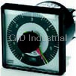
OMRON AUTOMATION H5L-A

Description
Timer Instrument 100VAC 240VAC Relay Output
H5L-A
Part Number
H5L-A
Price
Request Quote
Manufacturer
OMRON AUTOMATION
Lead Time
Request Quote
Category
Tools and Supplies » Timer Instrument
Specifications
Manufacturer
Omron Automation
Manufacturers Part #
H5L-A
Lead Time
4 Week Lead Time
Industry Aliases
H5L-A
Sub-Category
Timer Instruments
Factory Pack Quantity
1
Datasheet

Extracted Text
Daily Time Switch H5L CSM_H5L_DS_E_2_2 Weekly Control with a Large Time Display Easy Programming with Large Display and Interactive Functions. • Easy operation with five keys. Up to 24 steps of ON/OFF operations can be set. Power supply freely selectable from 100 to 240 VAC. Memory protection during power failure for up to 10 years. 96 mmCertified for UL and CSA safety standards. The same setting can be used for multiple-day operation and timer operation. Refer to Safety Precautions for All Timers. Refer to Safety Precautions on page 12 96 mm For the most recent information on models that have been certified for safety standards, refer to your OMRON website. Ordering Information Wiring Backup power supply function for memory No. of program steps Model protection Screw terminals Provided (approx. 10 years at 25°C) 24 (Each ON or OFF is considered to be one step.) H5L-A Specifications ■ Time Ranges Rated time Time setting range Time division 24 hrs x 7 days 00:00 to 23:59 1 min ■ Ratings Rated supply voltage 100 to 240 VAC (50/60 Hz) Operating voltage range 85% to 110% of rated supply voltage Power consumption Approx. 4 VA at 240 VAC Control outputs 15 A at 250 VAC, resistive load at 50°C 12 A at 250 VAC, resistive load at 55°C Minimum applied load: 100 mA at 5 VDC (failure level: P, reference value) 1 H5L ■ Characteristics Accuracy of operating time ±0.01% ±0.05 s max. (see note 1) Setting error Influence of voltage Influence of temperature Time accuracy ±15 s per month (at 25°C) Insulation resistance 100 MΩ min. Dielectric strength 2,000 VAC, 50/60 Hz for 1 min (between current-carrying terminals and exposed non-current-carrying metal parts and between control power supply circuit and contact control output circuits) 1,000 VAC, 50/60 Hz for 1 min (between non-continuous contacts) Vibration resistance Destruction: 10 to 55 Hz with 0.75-mm double amplitude Malfunction: 10 to 55 Hz with 0.5-mm double amplitude 2 Shock resistance Destruction: 300 m/s (approx. 30G) 2 Malfunction: 100 m/s (approx. 10G) Ambient temperature Operating: –10°C to 55°C Ambient humidity Operating: 35% to 85% Life expectancy 100,000 operations min. (15 A at 250 VAC, resistive load) Approved standards UL (File No. E52800), CSA (File No. LR22310) Weight Approx. 350 g Note: The overall error, which includes repeat accuracy, setting error, and variations due to changes in voltage and temperature, is ±0.01% or ±0.05 s max. The accuracy of ±0.01% also indicates the error in the time interval of the set time. Engineering Data Ambient Operating Temperature and Carry Current Note that the upper limit of the ambient operating temperature lowers when a large carry current is being applies as shown below. Carry current AC/DC (A) 2 Upper limit of ambient temperature (°C) H5L Nomenclature LCD Mode Key Write Key Plus Key Note: This figure shows the LCD section with all display items Minus Key being displayed on the screen. Cycle Key Manual override switch Key Operation Key Name Function Mode Key Changes program mode Write Key To write the set data using the Plus and/or Minus Key. Reads out the set program. Plus Key Changes “day of week” while setting day of week. Changes “hours” or “minutes” while setting current time. When the Plus Key is held down, the displayed digit increments continuously; when the Minus Key is held Minus Key down, it decrements continuously. When specifying output. The Plus Key specifies output ON while the Minus Key specifies output OFF. Note that if the same key is pressed twice, the output specification becomes invalid; neither ON nor OFF is set. Cycle Key Specifies the cycle program. Pressing this key twice causes the set cycle program to be cleared. Manual override ON: Turns ON output regardless of program switch RUN: Executes program OFF: Turns OFF output regardless of program First and second circuit can be operated independently. 3 H5L Operation ■ Programming The H5L Weekly Timer has the following six program modes. Use Setting Multiple-day Operation the Mode Key to change the modes. Use the Write Key, Plus Key, Example for Turning ON Circuit 1 Every Day from Monday to Friday Minus Key, and Cycle Key for programming in each mode. at 11:50 pm and Turning Circuit 1 OFF at 3:00 am the Next Morning Mode Change Sequence Programming Details Sun Mon Tue Wed Thu Fri Sat To set the current time in the order of "day of week", Current "hour" and "minute". time 23:50 3:00 1. Press the Mode Key for longer than 1 s to put setting the H5L in "TIM ADJ" mode. 1. Use the procedure First circuit operation setting given at the left to 2. Set "DAY OF WEEK" using the Plus and/or set the ON time to 23:50 and the OFF time to 3:00. Minus Keys. Then press the Write Key to write the set weekday. 2. Use the procedure First circuit weekday setting given at the left to 3. Set "hour" using the Plus and/or Minus Keys. set Monday, Tuesday, Wednesday, Thursday, and Friday. Then press the Write Key to write the set hour. 4. Set "minute" using Plus and/or Minus Keys. Cycle Program Then press the Write Key to write the set minute. In the H5L, the cycle program can be used to repeat ON and OFF of output for a certain period in a predetermined cycle. A cycle program First To specify first circuit operation in the order of consists of the following four steps: circuit "hour", "minute", and "output ON or OFF" operation Start time, ON time, OFF time, Stop time setting 1. Press the Mode Key to put the H5L in "PROG 1" mode. 2. Set "hour" using the Plus and/or Minus Keys. Then press the Write Key to write the set hour.Set minute" using the Plus and/or Minus Keys. Then press the Write Key to write the set minute. 3. Specify "ON" or "OFF" of output using the Plus or Minus Key and press the Write Key to write the set output specification. Setting A Cycle Program In this manner, set ON time and OFF time as many times as necessary. Set the four steps of the cycle program in the following procedure. First To set for each weekday whether the program for the first circuit circuit set in the previous step is to be executed or not. weekday Set the "hour" and "minute" of start 1. Press the Mode Key to put the H5L in "PROG 1" Setting setting start time using the Plus and/or Minus Key. "DAY SET" mode. time 2. Press the Plus Key to run the first circuit and press the Minus Key for it not to run. 3. Press the Write Key to change day of week. Setting Set the ON time of the cycle frequency Repeat steps 2 and 3 for Sunday to Saturday. ON in the order of "hour" and "minute". time Second To specify second circuit operation in the order of "hour", Set the OFF time of the cycle frequency Setting circuit "minute", and "output ON or OFF" OFF in the order of "hour" and "minute". operation time 1. Press the Mode Key to put the H5L in "PROG 2" setting mode. 2. Proceed with the settings in the same manner as in Setting the first circuit operation setting above. Set the stop time of the cycle program. stop time To set for each weekday whether the program for the Second second circuit set in the previous steps is to be executed circuit or not. On completing settings for the four weekday Normal setting program steps, the H5L returns automatically 1. Press the Mode Key to put the H5L in "PROG 2" "DAY mode to normal program mode. SET" mode. 2. Proceed with the settings in the same manner as in the first circuit operation setting above. Cautions on Using Cycle Programs Run the H5L using the set program. In RUN mode, the 1. When the current time is included within the set cycle period, the current time and output status are displayed but the cycle operation starts (output turns ON) on completing the cycle RUN operation mode is not displayed. After starting the H5L, the program setting (when stop time is written). colon between the hour" and minute" blinks to indicate that time count is in execution. 2. When any of the following occurs during a cycle period, the cycle operation restarts from output ON. Recovery after power failure Note: The H5L operates in accordance with the program already set Current time adjustment even while another program is being set. The output status display ( etc.) during programming displays the setting being Change of start or stop time of the cycle program during programmed. Therefore, note that the output status displayed on operation. For this reason, if the cycle programs for the first and the LCD may not agree with the actual output status. second circuits are set in such a manner that outputs 1 and 2 have a phase difference, note that the phase difference is changed when any of the conditions above occur as shown in the example below. (Therefore, it is recommended that cycle programs are used sequentially.) 4 H5L Recovery after power failure Output 1 and 2 start Note: Refer to "Programming simultaneously Example". 3. The cycle period (from start time to stop time) does not need to be a multiple of the cycle frequency (ON time plus OFF time). The cycle period can be set within a range of 1 min to 24 hrs. 4. ON time as well as OFF time can be set within a range of 1 min to 23 hrs 59 min. 5 H5L Deleting Programming 1. Deleting from Normal Operation Programs (ON Time/OFF 2. Deleting from Cyclic Programs Time) Four steps will be simultaneously deleted from the cyclic program Call up the output display for the program to be deleted by if the program is called up and then the Cycle and Write Keys are pressing the Write Key. The minus sign (–) for the output point will pressed in order. The start time display will remain, but the flash. program will be deleted. Next, change the display to disable the output using the Plus and Minus Keys. For NC contacts, press the Plus Key and for NO contacts, press the Minus Key. The connecting bar above the contacts will disappear and the display will flash to indicate that the output has been displayed. If the Write Key is pressed at this time, the step will be deleted. ■ LCD Display LCD Display (Display Example in Each Mode) Since the H5L employs interactive programming, the program mode and setting data are displayed on the LCD. Display Mode Display data Display Mode Display data RUN Current day of week: Second The second circuit turns ON Monday operation time Sunday to Thursday Current time:10:11 setting (operation by the set First circuit: OFF program is executed). It Second circuit: ON turns OFF on Friday and Saturday (operation by the set program stops). Current time Current day of week: Second The second circuit turns ON setting Tuesday Weekday Sunday to Thursday Current time: 9:31 setting (operation by the set program is executed). It turns OFF on Friday and Saturday (operation by the set program stops). First operation The first circuit turns on at Cycle Program The first circuit starts cycle time setting 8:15 setting operation at 1:10 (for details, refer to Cycle Program). First weekday The first circuit turns OFF Memory over Indicates that all 24 setting on Sunday and Saturday program steps have been (operation by the set written (on writing the 24th program stops). It turns ON step, the data set for the first Monday to Friday (operation step is displayed on the by the set program is LCD). executed). Note: Meaning of output status indications :Output ON, ; Output OFF, : Invalid (if an invalid instruction is written to a step, that step will be cleared.) ■ Programming Example Be sure to create a timing chart before programming. Operating Timing Chart First Circuit Second Circuit 6 H5L Example ON and OFF Programs Cyclic Programs In this example, the first circuit is programmed to turn ON at 7:40 and OFF at 19:30. This circuit is operated from Monday through Friday and stopped on Saturday and Sunday. The second circuit is cyclically operated with each parameter set as follows: Start time: 6:50 ON time: 5 min OFF time: 20 min Stop time: 20:30 The second circuit is stopped from operating on Sunday and operated from Monday through Saturday. The current time is assumed to be 11:15 a.m. on Tuesday. Writing Program Even while being programmed, the timer generates output according to the previous program. If you don’t want an unexpected operation of output relay, turn on (or off) the manual switch. In the figure, the indicators and digits shown in are blinking. 1. Setting Current Time To set the current time, "day of the week", "hour", and "minute" must be specified. First, turn on the power to the H5L. The contents of the memory are cleared on power-up and the TIM ADJ indicator is displayed as shown on the left.As an example, set the time to 11:15 on Tuesday. Start by setting the day of the week. The blinking indicator indicates the parameter that can be set. Set the current day of the week to Tuesday by pressing the Plus or Minus Key. When "TUE" is displayed, press the Write Key to store the current day of the week in memory. The "hour" indicator will begin to flash and the day of the week" indicator will stop flashing. Set the current hour to 11 by pressing the Plus or Minus Key, followed by the Write Key. At this time, the "minute" indicator will blink. Set the current minute to 15 by pressing the Plus or Minus Key, followed by the Write Key. This completes the current time setting. 7 H5L 2. First Circuit Operation Setting To program the operation of the first circuit, "hour", "minute", and "output" must be specified. Press the Mode Key to place the H5L into PROG 1 mode. The display will be as shown on the left. Since the first circuit is to be turned ON at 7:40, set the "hour" to 7 by pressing the Plus or Minus Key and then store it in memory by using the Write Key. The "minute" will start blinking. Set it to 40 by using the Plus or Minus Key and store it in memory by pressing the Write Key. Now, the output status indicator will blink. Set the output to the ON state with the Plus Key followed by the Write Key. (If the Plus Key is pressed twice at this time, the display will give an invalid indication, and if the Write Key is pressed, this program will be deleted.) The display returns to the initial state as shown on the left and waits for the next program command to be input. Since the first circuit should be turned OFF at 19:30, set the hour to 19 and the minute to 30 by using the Plus or Minus Key and then the Write Key. The output status indicator starts blinking. Set the output to the OFF state using the Minus Key and store it in memory by pressing the Write Key. The display returns to the initial state and waits for the next program command to be input. Now let us turn to the setting of the "day of the week". 3. Fist Circuit Day-of-the-week Setting By pressing the Mode Key, place the H5L into DAY SET mode. The display will be as shown on the left. Press the Plus Key to operate the first circuit on a particular day of the week and press the Minus Key to stop it. The reverse video (i.e., white characters on a black background) of the day-of-the-week indicators means that the first circuit is operated on that day. The day on which circuit operation is stopped is indicated by bold indicators. Initially, the circuit is set to operates on all the days of the week and the SUN indicator blinks. In this example, since circuit operation is to be stopped on Sunday, select SUN and press the Minus Key, then store the setting in memory by pressing the Write Key. The MON indicator will start blinking. Press the Write Key, until the SAT indicator blinks. Since the first circuit is not to be operated on Saturday, press the Minus Key followed by the Write Key. The SUN indicator will start blinking again. This completes the setting of all the days of the week for the first circuit. 8 H5L 4. Second Circuit Operation Setting Press the Mode Key to place the H5L into PROG 2 mode. The display appears as shown on the left. In this example, as the second circuit is to be cyclically operated, specify the cycle program by pressing the Cycle Key. Select the start time by setting the hour to 6 and the minute to 50 using pressing the Plus or Minus Key. Write each set value by pressing the Write Key. The timer will now wait for you to set the ON time (5 min in this example). Press the Write Key to select 0 hrs, then use the Plus or Minus Keys followed by the Write Key to select 5 min. The timer will now wait for the OFF time to be set (20 min in this example). Press the Write Key to select 0 hrs, then use the Plus or Minus Keys followed by the Write Key to select 20 min. The timer will now wait for the cyclic circuit operation stop time to be set (20:30 in this example). Set the hour to 20 using the Plus or Minus Keys, then press the Write Key. Set the minutes to 30 and press the Write Key again. The programming of the cyclic operation is now complete. The timer will wait for input of a new program as shown. We will now have to set the day of the week for the second circuit. 5. Second Circuit Day-of-the Week Setting Press the Mode Key to place the H5L into PROG 2, DAY WET mode. Initially, all days of the week are selected (shown by reverse video) and the SUN indicator will be flashing. In our example, the second circuit is to be operated on all days except Sunday. To inhibit Sunday operation, press the Minus Key while the SUN indicator is flashing. The circuit will now be operated only from Monday to Saturday. All of the parameters have now been programmed for this example. Press the Mode Key to place the timer into RUN mode. The display will be as shown (assuming five minutes have elapsed while programming). The output status indicators indicate the status of each of the circuit. Note: Set manual override switches 1 and 2 to RUN. 9 H5L Dimensions Note: All units are in millimeters unless otherwise indicated. H5L-A 56.5 96 42 6 14.5 4 96 12 35.3 91.9 M3.5 terminal screws Dimensions Panel Cutout Mounting Bracket (Included) Dimensions 59.8 (See note 1) 68.5 (See note 2) Note: 1. When using mounting track PFP-100N or PFP-50N. 2. When using mounting track PFP-100N2. Dimensions Panel Cutout Mounting Bracket (Included) Two, M4 taps Mounting bracket Panel 10 H5L ■ Accessories (Order Separately) Front Cover 16 42 Y92A-96A Mounting Track (Meets DIN EN 50022) PFP-100N/PFP-50N Note: 1. This dimension is 15 mm on both ends in the case of the PFP-100N but on one end in the case of the PFP-50N. (See note) (See note) (See note 2) 2. The length l of each mounting track is shown in this table. PFP-100N2 3. A total of twelve 25 × 4.5 elliptic holes are Twelve,-25 × 4.5 elliptic holes (See note 2) provided, with six holes cut from each end of the track at a pitch of 10 mm between holes. (See note) PFP-100N 1 m PFP-50N 50 cm PFP-100N2 1 m Installation ■ Connections Connect the power supply between terminals A and B, the load for the first circuit between terminals G and H, and the load for the second circuit between terminals E and F. Terminals C and D are no connects. Note: To each load, connect the power supply for load. 11 H5L Safety Precautions Refer to Safety Precautions for All Timers. Surface Mounting !CAUTION Use a straight mounting bracket to surface mount the unit. Tighten terminal screws to the specified torque of approx. 0.8 N·m (maximum torque: 0.98 N·m). Loose screws may occasionally cause fires or malfunction. The Time Switch contains a lithium battery (explosion- proof). Do not disassemble the Time Switch, deform the Time Switch under pressure, heat the Time Switch to above 100°C, or incinerate the Time Switch. Doing any of these may result in fire or battery rupture. ■ Precautions for Safe Use Observe all of the following precautions to maintain safety. 1. The Time Switch is not waterproof or oil resistant. Do not use it in locations subject to water or oil. Track Mounting 2. Use the following wire to wire the Time Switch: 600-V vinyl- insulated wire (solid wire or twisted wire, copper), 14 to 24 AWG Hook the upper part on the rear surface to the upper edge of the 3. Do not connect more than two crimp terminals to each Time mounting track and press the unit down. Switch terminal. (1) (2) 4. None of the Time Switch components are user-replaceable, including the battery. ■ Precautions for Correct Use Be sure that the capacity of the power supply is large enough, To remove the Timer Switch from the DIN Track, pull otherwise the Time Switch may not start due to the inrush current down on the yellow lever at the back of the Timer (approx. 3 A) that flows for an instant when the power to the Time Switch. Switch is turned ON. Wiring Yellow lever ON Current and Ambient Temperature Wiring From the Rear (Reference Values) Perform wiring from the rear of If the ON current is too large, the upper limit to the ambient operating the unit when the unit is flush temperature must be reduced as shown in the following diagram. mounted. 60 M3.5 terminal screws 55 Both circuits ON simultaneously 50 Wiring From the Front Perform wiring from the front of 40 the unit when the unit is track or surface mounted. 01 50121520 ON Current (A AC or DC) Mounting Dimensions Flush Mounting • Use a U-shaped mounting bracket to flush mount the unit. Wiring Procedure 1. Loosen the screw on the left side of the front. 2. Slide the upper part of the unit approx. 15 mm upward. 3. After the terminals appear, perform wiring. 4. Return the upper part of the unit to the original position and tighten the screw. Note: Screw tightening torque: 0.98 N·m max. 12 Upper limit to ambient operating temperature (°C) H5L ALL DIMENSIONS SHOWN ARE IN MILLIMETERS. To convert millimeters into inches, multiply by 0.03937. To convert grams into ounces, multiply by 0.03527. In the interest of product improvement, specifications are subject to change without notice. 13 Read and Understand This Catalog Please read and understand this catalog before purchasing the products. Please consult your OMRON representative if you have any questions or comments. Warranty and Limitations of Liability WARRANTY OMRON's exclusive warranty is that the products are free from defects in materials and workmanship for a period of one year (or other period if specified) from date of sale by OMRON. OMRON MAKES NO WARRANTY OR REPRESENTATION, EXPRESS OR IMPLIED, REGARDING NON-INFRINGEMENT, MERCHANTABILITY, OR FITNESS FOR PARTICULAR PURPOSE OF THE PRODUCTS. ANY BUYER OR USER ACKNOWLEDGES THAT THE BUYER OR USER ALONE HAS DETERMINED THAT THE PRODUCTS WILL SUITABLY MEET THE REQUIREMENTS OF THEIR INTENDED USE. OMRON DISCLAIMS ALL OTHER WARRANTIES, EXPRESS OR IMPLIED. LIMITATIONS OF LIABILITY OMRON SHALL NOT BE RESPONSIBLE FOR SPECIAL, INDIRECT, OR CONSEQUENTIAL DAMAGES, LOSS OF PROFITS OR COMMERCIAL LOSS IN ANY WAY CONNECTED WITH THE PRODUCTS, WHETHER SUCH CLAIM IS BASED ON CONTRACT, WARRANTY, NEGLIGENCE, OR STRICT LIABILITY. In no event shall the responsibility of OMRON for any act exceed the individual price of the product on which liability is asserted. IN NO EVENT SHALL OMRON BE RESPONSIBLE FOR WARRANTY, REPAIR, OR OTHER CLAIMS REGARDING THE PRODUCTS UNLESS OMRON'S ANALYSIS CONFIRMS THAT THE PRODUCTS WERE PROPERLY HANDLED, STORED, INSTALLED, AND MAINTAINED AND NOT SUBJECT TO CONTAMINATION, ABUSE, MISUSE, OR INAPPROPRIATE MODIFICATION OR REPAIR. Application Considerations SUITABILITY FOR USE OMRON shall not be responsible for conformity with any standards, codes, or regulations that apply to the combination of products in the customer's application or use of the products. At the customer's request, OMRON will provide applicable third party certification documents identifying ratings and limitations of use that apply to the products. This information by itself is not sufficient for a complete determination of the suitability of the products in combination with the end product, machine, system, or other application or use. The following are some examples of applications for which particular attention must be given. This is not intended to be an exhaustive list of all possible uses of the products, nor is it intended to imply that the uses listed may be suitable for the products: Outdoor use, uses involving potential chemical contamination or electrical interference, or conditions or uses not described in this catalog. Nuclear energy control systems, combustion systems, railroad systems, aviation systems, medical equipment, amusement machines, vehicles, safety equipment, and installations subject to separate industry or government regulations. Systems, machines, and equipment that could present a risk to life or property. Please know and observe all prohibitions of use applicable to the products. NEVER USE THE PRODUCTS FOR AN APPLICATION INVOLVING SERIOUS RISK TO LIFE OR PROPERTY WITHOUT ENSURING THAT THE SYSTEM AS A WHOLE HAS BEEN DESIGNED TO ADDRESS THE RISKS, AND THAT THE OMRON PRODUCTS ARE PROPERLY RATED AND INSTALLED FOR THE INTENDED USE WITHIN THE OVERALL EQUIPMENT OR SYSTEM. PROGRAMMABLE PRODUCTS OMRON shall not be responsible for the user's programming of a programmable product, or any consequence thereof. Disclaimers CHANGE IN SPECIFICATIONS Product specifications and accessories may be changed at any time based on improvements and other reasons. It is our practice to change model numbers when published ratings or features are changed, or when significant construction changes are made. However, some specifications of the products may be changed without any notice. When in doubt, special model numbers may be assigned to fix or establish key specifications for your application on your request. Please consult with your OMRON representative at any time to confirm actual specifications of purchased products. DIMENSIONS AND WEIGHTS Dimensions and weights are nominal and are not to be used for manufacturing purposes, even when tolerances are shown. PERFORMANCE DATA Performance data given in this catalog is provided as a guide for the user in determining suitability and does not constitute a warranty. It may represent the result of OMRON’s test conditions, and the users must correlate it to actual application requirements. Actual performance is subject to the OMRON Warranty and Limitations of Liability. ERRORS AND OMISSIONS The information in this document has been carefully checked and is believed to be accurate; however, no responsibility is assumed for clerical, typographical, or proofreading errors, or omissions. 2012.8 In the interest of product improvement, specifications are subject to change without notice. OMRON Corporation Industrial Automation Company http://www.ia.omron.com/ (c)Copyright OMRON Corporation 2012 All Right Reserved.
Frequently asked questions
How does Electronics Finder differ from its competitors?

Is there a warranty for the H5L-A?
Which carrier will Electronics Finder use to ship my parts?
Can I buy parts from Electronics Finder if I am outside the USA?
Which payment methods does Electronics Finder accept?
Why buy from GID?

Quality
We are industry veterans who take pride in our work

Protection
Avoid the dangers of risky trading in the gray market

Access
Our network of suppliers is ready and at your disposal

Savings
Maintain legacy systems to prevent costly downtime

Speed
Time is of the essence, and we are respectful of yours
Related Products
SPDT Timer Instrument 24VAC/12VDC 240VAC/240VDC Relay Output E3A2-10M4
SPDT Timer Instrument 24VAC/12VDC 240VAC/240VDC Relay Output E3A2-10M4D
SPDT Timer Instrument 24VAC/12VDC 240VAC/240VDC Relay Output E3A2-R3M4
SPDT Timer Instrument 24VAC/12VDC 240VAC/240VDC Relay Output E3A2-R3M4T
Mechatronic Analog Timer H3AM-NS-A-300AC100-240
Timer Instrument Relay Output H3BA-N110VAC
Request a Quote

The quote request has been received
Close

Facing challenges or have inquiries? Feel free to contact us!
Call Us +1-469-283-2440
What they say about us
FANTASTIC RESOURCE
One of our top priorities is maintaining our business with precision, and we are constantly looking for affiliates that can help us achieve our goal. With the aid of GID Industrial, our obsolete product management has never been more efficient. They have been a great resource to our company, and have quickly become a go-to supplier on our list!
Bucher Emhart Glass
EXCELLENT SERVICE
With our strict fundamentals and high expectations, we were surprised when we came across GID Industrial and their competitive pricing. When we approached them with our issue, they were incredibly confident in being able to provide us with a seamless solution at the best price for us. GID Industrial quickly understood our needs and provided us with excellent service, as well as fully tested product to ensure what we received would be the right fit for our company.
Fuji
HARD TO FIND A BETTER PROVIDER
Our company provides services to aid in the manufacture of technological products, such as semiconductors and flat panel displays, and often searching for distributors of obsolete product we require can waste time and money. Finding GID Industrial proved to be a great asset to our company, with cost effective solutions and superior knowledge on all of their materials, it’d be hard to find a better provider of obsolete or hard to find products.
Applied Materials
CONSISTENTLY DELIVERS QUALITY SOLUTIONS
Over the years, the equipment used in our company becomes discontinued, but they’re still of great use to us and our customers. Once these products are no longer available through the manufacturer, finding a reliable, quick supplier is a necessity, and luckily for us, GID Industrial has provided the most trustworthy, quality solutions to our obsolete component needs.
Nidec Vamco
TERRIFIC RESOURCE
This company has been a terrific help to us (I work for Trican Well Service) in sourcing the Micron Ram Memory we needed for our Siemens computers. Great service! And great pricing! I know when the product is shipping and when it will arrive, all the way through the ordering process.
Trican Well Service
GO TO SOURCE
When I can't find an obsolete part, I first call GID and they'll come up with my parts every time. Great customer service and follow up as well. Scott emails me from time to time to touch base and see if we're having trouble finding something.....which is often with our 25 yr old equipment.
ConAgra Foods