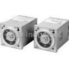
OMRON AUTOMATION H7ET-NV1-B
Specifications
Manufacturer
Omron Automation
Manufacturers Part #
H7ET-NV1-B
Lead Time
4 Week Lead Time
Industry Aliases
H7ET-NV1-B
Sub-Category
Timer Instruments
Factory Pack Quantity
1
Datasheet
Extracted Text
R Self-Powered Time Counter H7ET Subminiature Time Counters With Enhanced Appearance and Features H Large display with 8.6 mm (0.338 in) height H Available with backlit LCD H PNP/NPN DC voltage input available H Seven digits, time range 0 to 3999d23.9h H Key-protect switch to prevent front resetting H Selectable time range: 999999.9h or 3999d23.9h and 999h59m59s or 9999h59.9m H NEMA 4/IP66 front H Replaceable battery H New black case Ordering Information J TIME COUNTERS Count input p Disp playy Timerange 999999.9hor 3999d23.9h(selectable) 999h59m59s or 9999h59.9m(selectable) PNP/NPN universalDC 7-segment LCD H7ET-NV-BH H7ET-NV1-BH voltage g input p withbacklight 7-segment LCD H7ET-NV-B H7ET-NV1-B AC/DC multi-voltageinput 7-segment LCD H7ET-NFV-B H7ET-NFV1-B No-voltageinput 7-segment LCD H7ET-N-B H7ET-N1-B J MODELNUMBERLEGEND H7ET -N - 12 3 4 1.CountInput 3.CaseColor None: No-voltageinput B: Black V: PNP/NPN universalDC voltageinput FV: AC/DC multi-voltageinput 4.Display 2.TimeRange None: 7-segment LCD without backlight None: 999999.9h/3999d23.9h 1: 999h59m59s/9999h59.9m H: 7-segment LCD withbacklight J ACCESSORIES (ORDERSEPARATELY) Item Partnumber Replacement battery Y92S-36 Wire-wrapterminal(set of twoterminals) Y92S-37 Panel-mounting gadapt per 26mm× 45mm Y92F-75 24.8mm× 48.8mm Y92F-77B 1 H7ET H7ET Specifications J GENERAL Item H7ET-NV-B H7ET-NFV-B H7ET-N-B H7ET-NV1-B H7ET-NFV1-B H7ET-N1-B H7ET-NV-BH H7ET-NV1-BH Operatingmode UP type Mountingmethod Panelmounting Externalconnections Screw terminals, optionalwire-wrapterminals (SeeNote3.) Reset External/Manualreset Display 7-segment LCD withor without backlight (character height: 8.6mm) (SeeNote1.) Number of digits 7 Timerange 0.0hto999999.9hor 0.0hto3999d23.9h(switchable 0s to999h59m59s or 0.0mto9999h59.9m withswitch) (switchablewithswitch) Count input PNP/NPN AC/DC No-voltage PNP/NPN AC/DC No-voltage universalDC multi-voltage input universalDC multi-voltage input voltageinput input voltageinput input Casecolor Black Attachment Waterproof gasket, panel-mountingbracket, timeunit labels (SeeNote2.) Approvedstandard UL508, CSA C22.2No.14, Lloyds Conforms toEN61010-1/IEC61010-1(pollutiondegree2/overvoltagecategory III) Conforms toVDE0106/P100 Note: 1. Only PNP/NPN universalDC voltageinput models (-H models) areavailablewithabacklight. 2. “-hours,” “-d-h,” “-h-m,” and“-h-m-s” labels areincluded. 3. Wire-wrapterminals (Y92S--37) canbeorderedseparately. J RATINGS Item H7ET-NVj-B, H7ET-NVj-BH H7ET-NFVj-B H7ET-Nj-B Supply voltage Backlight model: 24VDC (for Not required(poweredby battery) backlight) No-backlight model: Not required (poweredby battery) Count input High(logic) level: 4.5to30VDC High(logic) level: 24to240VAC/ Novoltageinput Low (logic) level: 0to2VDC VDC, 50/60Hz Maximumshort-circuit impedance: (Input impedance: Approx. 4.7kΩ) Low (logic) level: 0to2.4VAC/ 10kΩmax. Short-circuit residualvoltage: g 0.5V VDC, 50/60Hz max. Reset input Novoltageinput Minimumopenimpedance: 750kΩ Maximumshort-circuit impedance: min. 10kΩmax. Short-circuit residualvoltage: 0.5V max. Minimumopenimpedance: 750kΩ min. Minimumpulsewidth 1s Reset system Externalreset andmanualreset: minimumsignalwidthof 20ms Terminalscrew 0.98NS mmax. tighteningtorque Ambient temperature Operating: --10°Cto55°C(14°F to131°F) withnocondensationor icing Storage: --25°Cto65°C(--13°F to149°F) withnocondensationor icing Ambient humidity Operating: 25%to85% 2 H7ET H7ET J CHARACTERISTICS Item H7ET-NVj-j H7ET-NFVj-j H7ET-Nj-j H7ET-NVj-Hj Timeaccuracy ±100ppm(25°C) Insulationresistance 100MΩmin. (at 500VDC) 100MΩmin. (at 500VDC) 100MΩmin. (at 500VDC) betweencurrent-carryingmetal betweencurrent-carryingmetal betweencurrent-carryingmetal parts andexposed parts andexposed parts andexposed non-current-carryingmetalparts, non-current-carryingmetalparts non-current-carryingmetalparts andbetweenthebacklight power andbetweencount input terminals supply andcount input andreset terminals terminals/reset terminals for backlight models Dielectric strength 1,000VAC, 50/60Hz for 1min 3,700VAC, 50/60Hz for 1min 1,000VAC, 50/60Hz for 1min betweencurrent-carryingmetal betweencount input terminals and betweencurrent-carryingmetal parts andexposed exposednon-current-carrying parts andexposed non-current-carryingmetalparts metalparts non-current-carryingmetalparts andbetweenthebacklight power 2,200VAC, 50/60Hz for 1min supply andcount input betweenreset terminals and terminals/reset terminals for exposednon-current-carrying backlight models metalparts andbetweencount input terminals andreset terminals Impulsewithstand 4.5kV betweencurrent-carrying 4.5kV betweencurrent-carrying 4.5kV betweencurrent-carrying voltage terminalandexposed terminalandexposed terminalandexposed non-current-carryingmetalparts non-current-carryingmetalparts non-current-carryingmetalparts 3kV betweeninput terminals and reset terminals Noiseimmunity Betweeninput terminals:±600V in Betweencount input terminals: ±500V innormalmode,±1.5kV in normalmode,±1.5kV incommand ±1.5kV innormalmode,±1.5kV in commandmode mode commandmode For backlight power supply Betweenreset input terminals: (backlight model):±480V in ±500V innormalmode,±1.5kV in normalmode,±1.5kV incommand commandmode mode Static immunity ±8kV (malfunction) Vibrationresistance Malfunction: 0.15-mmsingleamplitudeat 10to55Hz for 10mineachin3directions Destruction: 0.375-mmsingleamplitudeat 10to55Hz for 2hrs eachin3directions 2 Shock resistance Malfunction: 200m/s {approx. 20G} 3times eachin6directions 2 Destruction: 300m/s {approx. 30G} 3times eachin6directions Battery life 10years min. withcontinuous input at 25°C (lithiumbattery) EMC (EMI) EN50081-1 EmissionEnclosure: EN55022class B (EMS) EN50082-2 Immunity ESD: EN61000-4-2: 4-kV contact discharge(level2) 8-kV air discharge(level3) Immunity RF-interferencefromAMRadioWaves: ENV50140: 10V/m(80MHz to1GHz) (level3) Immunity RF-interferencefromPulse-modulatedRadioWaves: ENV50204: 20V/m(900MHz ± 5MHz) (level3) Immunity ConductedDisturbance: ENV50141: 10V (0.15to80MHz ) (level3) Immunity Burst: EN61000-4-4: 2-kV power line(level3) 2-kV I/O signalline(level4) Enclosurerating Front panel: IP66, NEMA4withwaterproof packing Terminalblock: IP20 Weight (seenote) Non-backlight model: Approx. 60g Approx. 60g Approx. 60g Backlight model: Approx. 65g Note: Weight includes waterproof gasket andpanel-mountingbracket. 3 H7ET H7ET Nomenclature J TIME COUNTER Front view ResetKey Reset thecount value. Not operable under key-protect. Key-protectSwitch Time-rangeswitch If theswitchsettingis changed, press theReset Setting Key onthefront panel. Key-protect (seenote) Front panel Timerange OFF Setting (default setting) Bottomview (seenote) H7ET-Njj-jj H7ET-Njj1-jj Front panel 0.0hto3999d23.9h 0s to999h59m59s ON (default setting) (default setting) Terminal block 0.0hto999999.9h 0.0mto9999h59.9m Terminal block Note: Performswitchsettingbeforemountingtoacontrolpanel. Operation J OPERATING MODES H7ETTimeCounter IncrementingOperation (Up) Reset Timer input Internal clock timer value Full-scale (Full-scale --0.1 (1)) Timer display values 4 H7ET H7ET Dimensions Unit: mm(inch) J H7ET-N 44.8 (1.76) PanelCutout Separatemounting 60 min. 24 22 (0.94) (0.87) 60 min. 48 48.5 +0.5 (1.89) (1.91) 45 0 +0.5 22.2 0 Joint mounting Dimensionswith Panel-Mounting Bracket +10 (48¢Units - 2.5) 0 +0.5 22.2 0 44.8 Waterproofingis not possible for joint mounting • Whenmounting, insert theCounter intothecutout. Insert theadapter fromtheback andpushinthe Counter whilemakingthegap betweenthefront panelandthe cutout panelas smallas possible. Usescrews tosecuretheCounter. If waterproofingis desired, insert the waterproof gasket. 37 35 24 (1.46) (1.38) • When several Counters are installed, ensure that the ambient temperature willnot exceedspecifications. • The appropriate thickness of the panel is 1to5mm. Installation J TERMINALARRANGEMENT Bottomview: View of theTimeCounter rotatedhorizontally 180° BacklightModel Non-backlightModel Backlight 24 VDC Timer Reset Reset Timer input input input input 5 H7ET H7ET Connections J PNP/NPNUNIVERSALDCVOLTAGE INPUTMODELWITHBACKLIGHT 1. Contact Input (Input by aRelay or SwitchContact) 2. Solid-stateInput Open collector of a Open collector of a Relay Relay PNP transistor PNP transistor Backlight Backlight 24 VDC 24 VDC Input Input Reset Reset or Switch or Switch or Open collector of an or Open collector of an NPN transistor NPN transistor Note: 1. Terminals 2 and 4 (input circuit and reset circuit) are functionally isolated. 2. Select input transistors accordingtothefollowing: Dielectric strengthof thecollector≧ 50V Leakagecurrent <1µA 6 H7ET H7ET J PNP/NPNUNIVERSALDCVOLTAGE J NO-VOLTAGE INPUTMODEL INPUTMODELWITHOUTBACKLIGHT 1. Contact Input (Input by aRelay or SwitchContact) 1. Contact Input (Input by aRelay or SwitchContact) Relay Relay Relay Relay Input Reset Input Reset Terminals 2and 4are internally connected. or Switch or Switch or Switch or Switch 2. Solid-stateInput Note: UseRelays andSwitches that havehighcontact Open collector of a Open collector of a reliability becausethecurrent flowingfrom PNP transistor PNP transistor terminals 1or 3is as smallas approx. 10µA. OMRON’s G3TA-IA/ID is recommendedas the Reset Input SSR. 2. Solid-stateInput (OpenCollector Input of anNPN Transistor) Open collector of an Open collector of an NPN transistor NPN transistor Input Reset or Open collector of an or Open collector of an NPN transistor NPN transistor Terminals 2and 4are internally connected. or Switch Note: 1. Residualvoltageintheoutput sectionof Proximity Sensors or Photoelectric Sensors becomes less Note: 1. Terminals 2and4(input circuit andreset circuit) than0.5V becausethecurrent flowingfrom arefunctionally isolated. terminals 1or 3is as smallas approx. 10µA, 2. Select input transistors accordingtothefollowing: allowingeasy connection. Dielectric strengthof thecollector≧ 50V 2. Select input transistors accordingtothefollowing: Leakagecurrent <1µA Dielectric strengthof thecollector≧ 50V Leakagecurrent <1µA J AC/DCMULTI-VOLTAGE INPUTMODEL Relay Relay Input Reset or Switch or Switch or Open collector of an NPN transistor 7 H7ET H7ET Accessories (Order Separately) AnH7ET is suppliedwithamountingbracket andnut. Inaddition, thepanel-mountingadapters shownhereallow theH7ET tobefittedto existingpanelcutouts. J Y92F-75 PANEL-MOUNTING ADAPTER FOR26¢ 45 RECTANGULARCUTOUT Must beusedwithmountingbracket suppliedwiththeCounter Two 3.5 dia. mounting holes Panelcutout Two M3 31 26 24.2 22.2 (1.22) (1.02) 26 4 45.2 45 48.2 63 63 (2.48) 72 (2.83) J Y92F-77BPANEL-MOUNTING ADAPTER FOR24.8¢ 48.8 RECTANGULARCUTOUT Must beusedwithmountingbracket suppliedwiththeCounter Panelcutout 28.8 24.8 24.2 22.2 (1.13) (0.98) 48.8 45.2 4 (1.92) 48.2 53.8 (2.12) 44.8 Y92S-37Wire-Wrap Terminal (Set of Two Terminals) (1.76) Wire-wrap terminal (1 × 1 mm) 24 22 (0.94) 48 48.5 2 17.1 (1.89) 5 65.6 (2.58) Thewire-wrapterminals haveacross sectionaldimensionof Wire Bit Sleeve Wrapped 1x1mm. Select oneof threeguages of wirefromthetableat state right. Alsolistedinthetableis theappropriatewiringhardware. AWG22 2-A 2-B Normal AWG24 1-A 1-B Normal AWG26 1-B 1-B Normal 8 H7ET H7ET J Y92S-36 REPLACEMENT(LITHIUM) BATTERY (3 V) 24.5 dia. 7.7 Precautions ! WARNING J BEFORE USE This product has a built-in lithium battery. Do not short-circuit the+and-- terminals,charge,disassemble,deform,orexpose Aninsulationsheet has beeninsertedtomaintainthequality of thebatterytofire.Thebatterymayexplode(break), catchfire, theTotalizer intheevent of alongperiodwithout use. Besureto or causeliquidleakage. removethis sheet beforeattemptingtousetheproduct. Removetheinsulationsheet andpress theReset Key onthe ! Caution front panelof theCounter. (WiththeH7ET-N,-NV(-H),-NV1(-H), models, “0” or “0.0” willbedisplayedafter 1s.) Donotuseanybatteryotherthanthespecifiedone(Y92S-36). Using another battery may cause liquidleakage or breakage, resultinginmalfunctionor injury. Insulation Sheet ! Caution If avoltageother thantheratedoneis applied, internal elements may bedamaged. Reset Key Donot usetheCounter inthefollowingplaces: • Locations subject todirect sunlight. Switchsettings ontheCounter must beperformedbefore • Locations subject tocorrosivegases. mountingit toacontrolpanel. • Locations subject todust. Donot usetheCounter inlocations subject to: SSeverechanges intemperature. SCondensationas theresult of hightemperatures. J MOUNTING PRECAUTIONS FOR PANEL-MOUNTING Althoughtheoperatingsectionis watertight (conformingto NEMA 4, IP66), arubber gasket is providedtoavoidwater leakagethroughthegapbetweentheCounter andpanelcutout. Unless this rubber gasket is tightly squeezedon, water may permeateinsidethepanel. For this reason, besuretotightenthe screws for fixingthepanel-mountingbracket. ScrewforthePanel-MountingBracket The wider side must Adapter Adapter screw section face the panel. 0.5 to 1 mm Tighten the screw until the distance is within the range shown above. Panel 9 H7ET H7ET J RESETINPUTANDCOUNTINPUT J INPUTANDPOWERSUPPLY TheH7ET operates usingaBattery. If theH7ET is connectedto Donot apply voltageontheCounter if theCounter is amodel adevicethat has +V andOUT terminals that areconnectedwith that operates withno-voltageinput, or theinternalcircuit of the adiodeas showninthecircuit diagram, thecircuit indicatedby Counter may bedamaged. thearrow 1or 2willbeformedwhenthedeviceis turnedOFF. As Donot connect any singleinput signalinparalleltoCounter aresult, theH7ET may bereset or count by one. Suchdevices models operatingwithno-voltageinput andthoseoperatingwith shouldnot beconnectedtotheH7ER. voltageinput, toavoidmalfunction. Whenconnectingasensor totheCounter that operates with no-voltageinput, makesurethat thesensor has opencollector output. Count input or reset input Sensor If anexcessivevoltageis appliedtothecount or reset input terminals, theinternalelements may bedamaged. Ensurethat thefollowingvoltages arenot exceeded: SPNP/NPN universalvoltageinput model: 30VDC Theoperationof theCounter may beaffectedif thelinevoltage SAC/DC voltageinput model: of thepower supply exceeds 500pF (about 10m, withparallel At count input: 240VAC (peak voltage: 338V) wires of 2x 2mm). Keepallwires as short as possible. When 240VDC usingshieldedwire, stray capacitancemay occur. At reset input: 3VDC (no-voltageinput) No-voltageinput model: 3VDC Whenconnectinganopencollector input fromatransistor tothe Counter that operates withno-voltageinput, makesurethat the Donot removetheouter casewhenvoltageis beingappliedto leakagecurrent of thetransistor is 5µA maximum. thepower supply terminals or totheinput terminals. Whenconnectingcount input fromanSSR totheCounter that Theinput for theH7Ej-NFV-jis ahigh-impedancecircuit so operates withAC/DC voltageinput, useOMRON’s G3TA-IA or influencefromaninducedvoltagemay result inmalfunction. G3TA-ID SSR. Otherwise, makesurethat theleakagecurrent of Whentheinput signalwiringis longer than10m(stray theSSR is 0.1mA maximumor connect ableeder resistor in capacitanceof 120pF/m, at roomtemperature), aCR filter or a paralleltotheinput circuit of theCounter. bleeder resistor shouldbeconnected. or Leakage current: J COUNTINPUTORRESETINPUTTO 0.1 mA max. or MORE THANONE H7ETCOUNTERAT ATIME or PNP/NPN UniversalDC VoltageInput *Bleeder resistor The voltage between terminals 1 and 2 must be 1.5 V maximum when the SSR is OFF. J BACKLIGHTPOWERSUPPLY or Toreducevariationinthebrightness of thebacklight whenusing morethanoneH7ET withabacklight, usethesamepower supply for allthebacklights. or Note: H (Reset ON) levelmust be4.5V minimum. 4.7(kΩ)/N +V WhenconnectingtheDC power supply for thebacklights, be H= 4.7(kΩ)/N +R suretoconnect thepolarities correctly. No-voltageInput J INPUTVERIFICATIONWITHTHE H7ET TIME COUNTER or The decimal point of the LCD blinks every other second while an input signalis beingapplied. If the decimalpoint is not blinking, the input signal is not being received correctly. Check the input signal Note: 1. Theleakagecurrent of thetransistor usedfor input connections. must beless than1µA. 2. Theforwardvoltageof thediodemust beas low as possible(i.e., 0.1V maximumwithanI of 20µA) so F thevoltagebetweenterminals 3and4willbe0.5V whenthereset input is ON. 10 Internal circuit H7ET H7ET J UNITLABELFORTIME COUNTERAND J EN/IECSTANDARDS TACHOMETER Thecounter input, reset input, andbacklight power supply terminals of theno-voltageinput or PNP/NPN universalDC A unit labelhas beenpackedwiththeCounter. Usein voltageinput models (H7Ej-N,-N1, H7Ej-NV(-H),-NV1(-H)) are accordancewiththeapplication. not isolated. A SELV power supply conformingtoAppendix H of IEC61010-1 shouldbeusedfor thecounter input, reset input andbacklight power supply terminals. A SELV power supply is apower supply for whichtheinput andoutput havedoubleor reinforced insulation, andfor whichtheoutput voltageis 30Vrems with42.4 V peak or 60VDC max. (Only theH7Ej-NVj-H has a J BATTERY REPLACEMENT backlight.) RemovethewiringwhenreplacingtheBattery. Donot comein Theterminals for counter input andreset input for AC/DC contact withany itemtowhichhighvoltageis beingapplied. multi-voltageinput models havebasic insulation. Doingsomay result inelectric shock. Connect thereset input terminals toadevicethat does not have BeforechangingtheBattery, besurethat youarenot carrying exposedcurrent-carryingparts andhas basic insulationfor any static electric charge. 240VAC. Procedurefor replacingtheBattery (refer tothediagrams below): 1. Usingthetool, pry openthelift-tabonthecase. (1) 2. Pullthebody out of its outer case. (2) 3. Lift theBattery upby theedgeandremoveit. (3) When removing the Battery, do not come in contact with the display areaor any internalparts. 4. Wipetheback of thenew Battery beforeinsertingit. 5. Ensurethat the+and -- terminals arecorrectly oriented. 6. AfterreplacingtheBattery,re-insertthebodyintoitscase.(4) Check that thecaseis securely heldinby thelift-tab. 7. Press the Reset Key before use (not necessary for H7ET-N,-NV,-NV1). (5) WhentheinternalBattery nears expiration, thedisplay may flicker. (2) (1) Tool (1) (3) (4) (5) 11 H7ET H7ET NOTE:DIMENSIONSSHOWNAREINMILLIMETERS.Toconvertmillimeterstoinchesdivideby25.4. R OMRONELECTRONICS LLC OMRONON--LINE OMRONCANADA, INC. OneEast CommerceDrive 885MilnerAvenue Global -- http://www.omron.com Schaumburg, IL60173 Scarborough, OntarioM1B 5V8 USA -- http://www.omron.com/oei Canada -- http://www.omron.com/oci 1-800-55-OMRON 416-286-6465 C at . N o. G C T MC N 1 3/ 02 S pec if ic at ions s ubjec t t o c hange w it hout not ic e. P r int ed in U . S . A . 12
Frequently asked questions
How does Electronics Finder differ from its competitors?

Is there a warranty for the H7ET-NV1-B?

Which carrier will Electronics Finder use to ship my parts?

Can I buy parts from Electronics Finder if I am outside the USA?

Which payment methods does Electronics Finder accept?

Why buy from GID?

Quality
We are industry veterans who take pride in our work

Protection
Avoid the dangers of risky trading in the gray market

Access
Our network of suppliers is ready and at your disposal

Savings
Maintain legacy systems to prevent costly downtime

Speed
Time is of the essence, and we are respectful of yours


 Manufacturers


What they say about us
FANTASTIC RESOURCE
One of our top priorities is maintaining our business with precision, and we are constantly looking for affiliates that can help us achieve our goal. With the aid of GID Industrial, our obsolete product management has never been more efficient. They have been a great resource to our company, and have quickly become a go-to supplier on our list!
Bucher Emhart Glass
EXCELLENT SERVICE
With our strict fundamentals and high expectations, we were surprised when we came across GID Industrial and their competitive pricing. When we approached them with our issue, they were incredibly confident in being able to provide us with a seamless solution at the best price for us. GID Industrial quickly understood our needs and provided us with excellent service, as well as fully tested product to ensure what we received would be the right fit for our company.
Fuji
HARD TO FIND A BETTER PROVIDER
Our company provides services to aid in the manufacture of technological products, such as semiconductors and flat panel displays, and often searching for distributors of obsolete product we require can waste time and money. Finding GID Industrial proved to be a great asset to our company, with cost effective solutions and superior knowledge on all of their materials, it’d be hard to find a better provider of obsolete or hard to find products.
Applied Materials
CONSISTENTLY DELIVERS QUALITY SOLUTIONS
Over the years, the equipment used in our company becomes discontinued, but they’re still of great use to us and our customers. Once these products are no longer available through the manufacturer, finding a reliable, quick supplier is a necessity, and luckily for us, GID Industrial has provided the most trustworthy, quality solutions to our obsolete component needs.
Nidec Vamco
TERRIFIC RESOURCE
This company has been a terrific help to us (I work for Trican Well Service) in sourcing the Micron Ram Memory we needed for our Siemens computers. Great service! And great pricing! I know when the product is shipping and when it will arrive, all the way through the ordering process.
Trican Well Service
GO TO SOURCE
When I can't find an obsolete part, I first call GID and they'll come up with my parts every time. Great customer service and follow up as well. Scott emails me from time to time to touch base and see if we're having trouble finding something.....which is often with our 25 yr old equipment.
ConAgra Foods