

 Manufacturers
OMRON AUTOMATION HL5500

Description
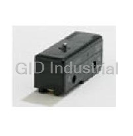
Switch Limit N.O./N.C. SPDT Remote Control Wire Conduit 5A 250VAC 24VDC 19.61N Screw Mount
HL5500
Part Number
HL5500
Price
Request Quote
Manufacturer
OMRON AUTOMATION
Lead Time
Request Quote
Category
Switches » Switch Limit
Specifications
Manufacturer
Omron Automation
Manufacturers Part #
HL5500
Lead Time
52 Week Lead Time
Industry Aliases
HL5500
Sub-Category
Limit Switches
Factory Pack Quantity
1
Datasheet

Extracted Text
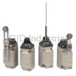
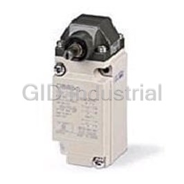
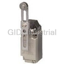
General-purpose Limit Switch HL-5000 Economical, Miniature Limit Switch Boasting Rigid Construction ■ The Head, Box, and Cover mate with ridged surfaces to maintain strength. ■ A unique Head structure provides a large OT for smooth operation. ■ Easy-to-wire conduit opening design. ■ Ideal for application in printing machines, forming machines, and light machines. (High Switches with high sealing characteristics, such as WL or D4C Switches, in locations subject to oil, water, or precipitation.) ■ Models with grounding terminals conform to the CE marking. ■ Approved by CCC (Chinese standard). (Ask your OMRON representative for information on approved models.) Be sure to read Safety Precautions on page 4 to 5 and Safety Precautions for All Limit Switches. Model Number Structure Specifications Model Number Legend Approved Standards HL-5@@ Agency Standard File No. å`HL-5ņņ (1)(2) CCC (CQC) GB14048.5 2003010303077624 (1) Actuators Note: Ask your OMRON representative for information on approved models. 000: Roller lever Ratings 030: Adjustable roller lever 050: Adjustable rod lever Non-inductive load (A) Inductive load (A) 100: Sealed plunger Rated Resistive Inductive Lamp load Motor load 200: Sealed roller plunger voltage load load 300: Coil spring NC NO NC NO NC NO NC NO (2) Ground Terminal Specifications 125 VAC 5 1.5 0.7 3 2 1 250 VAC 5 1 0.5 3 1.5 0.8 Blank : Without ground terminal 12 VDC 534 3 G : With ground terminal/M5 tapping on the rear side 24 VDC 534 3 125 VDC 0.4 0.2 −− − Ordering Information 250 VDC 0.4 0.2 −− − Note: 1. The above figures are for steady-state currents. Actuator Model 2. Inductive loads have a power factor of 0.4 min. (AC) and a time constant of 7 ms max. (DC). Roller lever HL-5000 * 3. Lamp load has an inrush current of 10 times the steady-state current. 4. Motor load has an inrush current of 6 times the steady-state current. Adjustable HL-5030 * NC 24 A max. Inrush roller lever current NO 12 A max. Adjustable HL-5050 * Approved Standard Ratings rod lever CCC (GB14048.5) Sealed HL-5100 * Applicable category and ratings plunger AC-15 3 A/250 VAC Sealed roller HL-5200 plunger Coil spring HL-5300 * HL-5000 Limit Switches are offered with a choice of ground terminal/M5 tapping on the rear side conforming to various standards. When placing an order, add the code to the model number to indicate if ground terminal/M5 tapping on the rear side is required. -G: with ground terminal/M5 tapping on the rear side. http://www.ia.omron.com/ (c)Copyright OMRON Corporation 2007 All Rights Reserved. 1 HL-5000 Characteristics Engineering Data Electrical Durability (cos dia. =1) Degree of protection IP65 (Operating temperature: +5°C to +35°C, 10,000,000 operations min. (under Mechanical Operating humidity: 40% to 70%RH) rated conditions) Durability * Electrical See the following Electrical Durability. Operating frequency: 1,000 30 operations/min Operating speed 5 mm/s to 0.5 m/s 125 VAC (cos dia. = 1) Mechanical 120 operations/min Operating frequency Electrical 30 operations/min Insulation resistance 100 MΩ min. (at 500 VDC) Contact resistance 25 mΩ max. (initial value) 1,000 VAC, 50/60 Hz for 1 min between 500 terminals of the same polarity 1,500 VAC, 50/60 Hz for 1 min between Dielectric strength current-carrying metal parts and ground 1,500 VAC, 50/60 Hz for 1 min between each terminal and non-current-carrying metal part 0 12 3 4 5 6 Rated frequency 50/60 Hz Switching current (A) Vibration Malfunction 10 to 55 Hz, 1.5-mm double amplitude resistance 2 Destruction 1,000 m/s min. Shock 2 resistance Malfunction 300 m/s min. Ambient operating −5°C to +65°C (with no icing) temperature Ambient operating 35% to 95%RH humidity Weight Approx. 130 to 190 g Note: 1. The above figures are initial values. 2. The above characteristics may vary depending on the model. For further details, contact your OMRON sales representative. * The values are calculated at an operating temperature of +5°C to +35°C, and an operating humidity of 40% to 70%RH. Contact your OMRON sales representative for more detailed information on other operating environments. Structure and Nomenclature Structure Contact Form Za (NO) 4 3 (NO) Resin roller Lever (NC) 1 2 (NC) Head Cover Built-in switch Connector http://www.ia.omron.com/ (c)Copyright OMRON Corporation 2007 All Rights Reserved. 2 4 Durability (x 10 operations) HL-5000 Dimensions and Operating Characteristics (Unit: mm) Switches (Dimensions not shown are the same as roller lever models.) ±0.8 Roller Lever 58 Adjustable Roller Lever ±0.8 65.7 ±0.8 53 HL-5000 HL-5030 ±0.8 17.5 dia. × 6.6 60.3 ±0.8 39.5 resin roller *1 17.5 dia.× 6.6 *1 51.3±0.8 40.3±0.8 ±0.8 39.5 Adjustable 32 up to 30R 31.5R 16.5 16.5 to 75R *2 *2 21.4 21.4 M5× 16 15.5 15.5 Allen-head M5× 12 bolt (110) Allen-head bolt M5× 12 60.6 60.6 50±0.2 50±0.2 Allen-head Three, M3 bolt 4.1 Three, M3 (19) (19) 4.1 ±0.2 24 18.5 +0.2 Two, 5.2 dia. 0 Rubber *1. Resin roller mounting holes 33 33 *2. The head can be mounted in any of the four directions. connector 34 *1. The lever can be mounted anywhere in 360°. *2. The head can be mounted in any of the four directions. Adjustable Rod Lever Sealed Plunger 62.8±0.8 5.4 ±0.8 HL-5050 53.4 HL-5100 3 dia.× 160 *1 39.5±0.8 * 8 dia. 145 max. 32 PT 16.5 16.5 *2 Two, M3 21.4 20.2 OP M5× 16 15.5 Allen-head bolt M5× 12 60.6 ±0.2 60.6 ±0.2 50 50 Allen-head bolt 4.1 Three, M3 Three, M3 (19) (19) 4.1 * Stainless steel plunger *1. Stainless steel rod *2. The head can be mounted in any of the four directions. Sealed Roller Plunger Coil Spring *2 6.6 dia. *1 HL-5200 HL-5300 PT 3.2 dia. 30 *2 ±0.2 38 12.7 dia.× 4.8 *1 PT 16.5 ±2.5 110 ±0.2 Two, M3 42 Two, M3 16.5 OP *2 20.2 20.2 Three, M3 ±0.2 60.6 50 Three, M3 ±0.2 60.6 50 4.1 (19) 4.1 (19) *1. Stainless sintered alloy roller *1. Resin rod *2. The head can be mounted in either of the two directions. *2. The coil spring may be operated from any directions except axial directions ( ). *3. The operating range of the dog or cam is the top third (i.e. from the tip of the rod) of the whole actuator. Note: Unless otherwise specified, a tolerance of ±0.4 mm applies to all dimensions. Operating Model HL-5000 HL-5030 * HL-5050 * HL-5100 HL-5200 HL-5300 characteristics Operating force OF max. 7.35 N 7.35 N 7.35 N 8.83 N 8.83 N 1.47 N Release force RF min. 0.98 N 0.98 N 0.98 N 1.47 N 1.47 N − Pretravel PT max. 20° 20° 20° 1.5 mm 1.5 mm 30 mm Overtravel OT min. 50° 50° 50° 4 mm 4 mm − Movement Differential MD max. 12° 12° 12° 1 mm 1 mm − Operating position OP −−− 30±0.8 mm 40±0.8 mm − * Measured with the types of the 31.5-mm arm or rod length. OF and RF measured at the arm length of 75 mm for HL-5030, and 145 mm for HL-5050 (reference values). HL-5030 HL-5050 OF 3.09 N 1.60 N RF 0.41 N 0.22 N http://www.ia.omron.com/ (c)Copyright OMRON Corporation 2007 All Rights Reserved. 3 HL-5000 Safety Precautions For details, be sure to read Safety Precautions for All Limit Switches. Precautions for Correct Use Operating Environment Applicable Lead Wires • Seal material may deteriorate if a Switch is used outdoor or where Applicable wire subject to special cutting oils, solvents, or chemicals. Always Wire name Number of Conductor External appraise performance under actual application conditions and set conductors size size suitable maintenance and replacement periods. 2 Vinyl cabtire cord • Install Switches where they will not be directly subject to cutting 2 3 0.75 mm (VCTF) chips, dust, or dirt. The Actuator and Switch must also be protected Round, 6 to 9 4 dia. from the accumulation of cutting chips or sludge. Vinyl cabtire cable 2 2 0.75 mm Flat, 9.4 (VCT) Not Suitable Suitable max. 600-V vinyl-insulated 1 dia./1.2 dia./ 2 sheath cable (VVF) 1.6 dia. Note: Do not use wires containing silicone, otherwise a contact failure may result. Applicable Solderless Terminal • Constantly subjecting a Switch to vibration or shock can result in The following solderless terminals are available. Do not use fork or wear, which can lead to contact interference with contacts, operation failure, reduced durability, and other problems. any other type of terminals, otherwise an accidental disconnection resulting in a ground fault may result. Excessive vibration or shock can lead to false contact operation or damage. Install Switches in locations not subject to shock and Terminal with insulated grip vibration and in orientations that will not produce resonance. 6.4 max. 6.4 max. • The Switches have physical contacts. Using them in environments containing silicon gas will result in the formation of silicon oxide (SiO2) due to arc energy. If silicon oxide accumulates on the contacts, contact interference can occur. If silicon oil, silicon filling 14 max. 14 max. agents, silicon cables, or other silicon products are present near the 3.0 to 3.0 to Switch, suppress arcing with contact protective circuits (surge 3.7 dia. 3.7 dia. killers) or remove the source of silicon gas. Wiring Appropriate Tightening Torque Wiring Procedure A loose screw may result in a malfunction. Be sure to tighten each 1. Loosen the cover mounting screws and remove the cover. screw to the appropriate tightening torque as shown below. 2. Disconnect the rubber connector from the box conduit and pressfit Appropriate a solderless terminal. The following solderless terminals are No. Type tightening torque available. 1 Head mounting screw 0.49 to 0.59 N·m 3. After inserting the solderless terminal into the Switch, tighten the 2 Cover mounting screw 0.49 to 0.59 N·m terminal screws securely. 3 Allen-head bolt 4.90 to 5.88 N·m 4. After wiring the Limit Switch, insert the rubber connector into the groove of the box securely. 4 Terminal screw (M3 screw) 0.49 to 0.59 N·m 5. Tighten the three mounting screws evenly. The optimum tightening Switch mounting screw 5 4.90 to 5.88 N·m torque for each screw is 0.49 to 0.59 N·m. (M5 Allen-head bolt) Note: If the head direction has been changed, check the torque of each screw Cover mounting screw and make sure that the screws are free of foreign substances, and that Cover each screw is tightened to the proper torque. Rubber connector 1 3 Terminal 4 2 5 http://www.ia.omron.com/ (c)Copyright OMRON Corporation 2007 All Rights Reserved. 4 HL-5000 Mounting Others To mount the Limit Switch securely, be sure to use two M5 Allenhead • Do not use the Limit Switch outdoors, otherwise the Limit Switch will bolts and washers. become damaged by rust or ozone. The tightening torque applied to each bolt is 4.90 to 5.88 N·m. To • The Limit Switch is not suitable in places exposed to the spray of mount the Limit Switch more securely, use two M5 screw holes on the rainwater, seawater, or oily water. Consult your OMRON rear panel and rear holes for positioning if the model is the HL- representative for models resisting rainwater, seawater, and oily 5@@@G-Series Limit Switches. water. • If high-sealing performance is required along with shielded wiring or Mounting holes Two, 5.2-dia. holes (located conduit wiring, use the D4C or WL. diagonally for securing the rear side) 50±0.15 ±0.15 24 Two, M5 screws or 5.2-dia. holes (located diagonally for securing the front side) Only the HL-5@@@G has M5 x 0.8 screw holes on the rear side. Using the Switches Actuator Position Change Head Direction Change (HL-5000, HL-5030, HL-5050) (HL-5000, HL-5030, HL-5050, HL5200) To change the angle of the actuator, loosen the Allen-head bolt on the To change the head direction, loosen the two mounting screws. Then side of the actuator lever. Then the actuator can be set at any angle. the head can be changed at 90° increments in one of four directions. HL-5000 Head mounting HL-5030 screw (Small white screw that can be Head mounting screw turned with either (Black non-removable a Phillips-head or torque screw) flat-blade screw- driver) Loosen the Allenhead Head mounting screw (Small white screw that bold Head mounting screw can be turned with either (Black non-removable a Phillips head or torque screw) flat-blade screwdriver) HL-5050 The head of the HL-5200 can be mounted in two directions only. (Refer to the following illustration.) HL-5200 Head mounting screw (white) Head mounting screw (white) http://www.ia.omron.com/ (c)Copyright OMRON Corporation 2007 All Rights Reserved. 5 Precautions for All Limit Switches (Not including Safety Switches) Note: Refer to the Precautions section for each Switch for specific precautions applicable to each Switch. Precautions for Safe Use • If the Switch is to be used as a switch in an emergency stop circuit Mounting or in a safety circuit for preventing accidents resulting in injuries or • Do not modify the actuator, otherwise the operating characteristics deaths, use a Switch with a direct opening mechanism, use the NC and performance of the actuator will change. contacts with a forced release mechanism, and set the Switch so • Do not enlarge the mounting holes of the Switch or modify the that it will operate in direct opening mode. Switch. Doing so may result in insulation failures, housing damage, For safety, install the Switch using one-way rotational screws or or physical injuries. other similar means to prevent it from easily being removed. Protect • Be sure to evaluate the Switch under actual working conditions the Switch with an appropriate cover and post a warning sign near after installation. the Switch in order to ensure the safety. • Do not apply oil, grease, or other lubricants to the moving parts of • Do not supply electric power when wiring. Otherwise electric shock the actuator, otherwise the actuator may not operate correctly. may result. Furthermore, intrusion of oil, grease, or other lubricants inside the • Keep the electrical load below the rated value. Switch may reduce sliding characteristic or cause failures in the • Be sure to evaluate the Switch under actual working conditions Switch. after installation. • Mount the Switch and secure it with the specified screws tightened • Do not touch the charged switch terminals while the Switch has to the specified torque along with flat washers and springs. The carry current, otherwise electric shock may result. actuator of a Pushbutton Limit Switch mounted to a panel with • If the Switch has a ground terminal, be sure to connect the ground excessive tightening torque may not operate correctly. terminal to a ground wire. • Be sure to wire the Switch so that the conduit opening is free of • Do not disassemble the Switch while electric power is being supply. metal powder or any other impurities. Otherwise electric shock may result. • If glue or bonding agent is applied, make sure that it does not • The durability of the Switch greatly varies with switching conditions. adhere to the movable parts or intrude inside the Switch, otherwise Before using the Switch, be sure to test the Switch under actual the Switch may not work correctly or cause contact failure. Some conditions. Make sure that the number of switching operations is types of glue or bonding agent may generate a gas that may have within the permissible range. a bad influence on the Switch. Pay the utmost attention when If a deteriorated Switch is used continuously, insulation failures, selecting the glue or locking agent. contact weld, contact failures, switch damage, or switch burnout • Do not drop or disassemble the Switch, otherwise the Switch will may result. not be capable of full performance. Furthermore, the Switch may • Maintain an appropriate insulation distance between wires become broken or burnt. connected to the Switch. • Some models allow changes in head directions. When changing • Some types of load have a great difference between normal current the head of such a model, make sure that the head is free of any and inrush current. Make sure that the inrush current is within the foreign substance. Tighten each screw of the head to the rated permissible value. The greater the inrush current in the closed torque. circuit is, the greater the contact abrasion or shift will be. • Be sure to take measures so that no foreign material, oil, or water Consequently, contact weld, contact separation failures, or will penetrate into the Switch through the conduit opening. Be sure insulation failures may result. Furthermore, the Switch may become to attach a connector suited to the cable thickness and tighten the broken or damaged. connector securely to the rated torque. I • Do not impose shock or vibration on the actuator while it is fully (A) pressed. Otherwise, the actuator will partially abrade and an actuation failure may result. Wiring i (Inrush current) • If the wiring method is incorrect, the wires may get caught on objects or the lead wires may be pulled excessively. Make sure that the lead wires are sufficiently long and secure them along the wiring path. Incorrect Correct io (Constant current) t Terminal box Terminal box Wiring Pay the utmost attention so that each terminal is wired correctly. • Pay the utmost attention so that each terminal is wired correctly. If If the terminal is wired incorrectly, the Switch will not function. a terminal is wired incorrectly, the Limit Switch will not function Furthermore, not only will the Switch have a bad influence on the properly. Furthermore, not only will the Limit Switch have an external circuit, the Switch itself may become damaged or burnt. adverse influence on external circuits, the Limit Switch itself may become damaged or burnt. Precautions for Correct Use For details, refer to Precautions for Correct Use in the Technical Guide for Limit Switches. http://www.ia.omron.com/ (c)Copyright OMRON Corporation 2007 All Rights Reserved. C-1 Technical Guide for Limit Switches Precautions for Correct Use Switch Operation • The following graph shows an example of changes in contact force according to the stroke. The contact force near the OP or RP is • The Switch in actual operation may cause accidents that cannot be unstable, and the Limit Switch cannot maintain high reliability. foreseen from the design stage. Therefore, the Switch must be Furthermore, the Limit Switch cannot withstand strong vibration or practically tested before actual use. shock. • When testing the Switch, be sure to apply the actual load condition together with the actual operating environment. • All the performance ratings in this catalog are provided under the following conditions unless otherwise specified. Inductive load: A minimum power factor of 0.4 (AC) or a maximum time constant of 7 ms (DC) Lamp load: Stroke An inrush current 10 times higher than the normal current Motor load: An inrush current 6 times higher than the normal current (1) Ambient temperature: +5°C to +35°C FP (2) Ambient humidity: 40% to 70%RH Changes to opposite side Note: An inductive load causes a problem especially in DC circuitry. Therefore, Stroke it is essential to know the time constants (L/R) of the load. Changes to opposite side OTP Solenoid (Approximately 10 to 20 times higher) Incandescent lamp (Approximately 10 to 15 times higher) Motor • If the Limit Switch is used so that the actuator is constantly pressed, (Approximately 5 to 10 times higher) it will fail quickly and reset faults may occur. Inspect the Limit Switch Relay periodically and replace it as required. (Approximately 4 to 5 times higher) Mechanical Conditions for Switch Selection • The actuator must be selected according to the operating method. (Refer to page 9.) • Check the operating speed and switching frequency. 1. If the operating speed is extremely low, the switching of the movable contact will become unstable, thus resulting in incorrect Mechanical Characteristics contact or contact weld. Operating Force, Stroke, and Contact Characteristics 2. If the operating speed is extremely high, the Switch may break due • The following graph indicates the relationship between operating to shock. If the switching frequency is high, the switching of the force and stroke or stroke and contact force. In order to operate the contacts cannot catch up with the switching frequency. Make Limit Switch with high reliability, it is necessary to use the Limit sure that the switching frequency is within the rated switching Switch within an appropriate contact force range. If the Limit Switch frequency. is used in a normally closed condition, the dog must be installed so • Do not impose excessive force on the actuator, otherwise the that the actuator will return to the FP when the actuator is actuated actuator may become damaged or not operate correctly. by the dog. If the Limit Switch is used in a normally open condition, • Make sure that the stroke is set within the suitable range specified the actuator must be pressed to 70% to 100% of the OT (i.e., 60% for the model, or otherwise the Switch may break. to 80% of the TT) and any slight fluctuation must be absorbed by the actuator. Electrical Characteristics • If the full stroke is set close to the OP or RP, contact instability may Electrical Characteristics for Switch Selection result. If the full stroke is set to the TTP, the actuator or switch may • The switching load capacity of the Switch greatly varies between become damaged due to the inertia of the dog. In that case, adjust AC and DC. Always be sure to apply the rated load. The control the stroke with the mounting panel or the dog. capacity will drastically drop if it is a DC load. This is because a DC Refer to page 11, Dog Design, page 12, Stroke Settings vs. Dog load has no current zero-cross point, unlike an AC load. Therefore, Movement Distance, and page 12, Dog Surface for details. if an arc is generated, it may continue comparatively for a long time. Furthermore, the current direction is always the same, which results in a contact relocation phenomena whereby the contacts easily stick to each other and do not separate when the surfaces of the contacts are uneven. • If the load is inductive, counter-electromotive voltage will be generated. The higher the voltage is, the higher the generated energy will be, which will increase the abrasion of the contacts and contact relocation phenomena. Be sure to use the Switch within the rated conditions. • If the load is a minute voltage or current load, use a dedicated Switch for minute loads. The reliability of silver-plated contacts, which are used by standard Switches, will be insufficient if the load is a minute voltage or current load. http://www.ia.omron.com/ (c)Copyright OMRON Corporation 2007 All Rights Reserved. C-2 Contact force Operating force Technical Guide for Limit Switches Contact Protective Circuit Apply a contact protective circuit to increase the contact durability, may generate NOx, which will change into HNO3 if it reacts with prevent noise, and suppress the generation of carbide or nitric acid. moisture. Be sure to apply the contact protective circuit correctly, otherwise an Consequently, the internal metal parts may corrode and the Switch adverse effect may occur. may fail. Be sure to select the ideal contact preventive circuit from the The following provides typical examples of contact protective circuits. following. If the Switch is used in an excessively humid location for switching a Also, load operating times may be delayed somewhat if a contact load that easily generates arcs, such as an inductive load, the arcs protective circuit (a surge killer) is used. Typical Examples of Contact Protective Circuits Applicable current Circuit example Feature and details Element selection AC DC C: 1 to 0.5 μF × switching current (A) R: 0.5 to 1 Ω× switching voltage (V) The values may change according to the charac- Condi- * When AC is switched, the load impedance must CR Inductive O teristics of the load. Power load tional * be lower than the CR impedance. The capacitor suppresses the spark discharge of supply current when the contacts are open. The resistor limits the inrush current when the contacts are closed again. Consider the roles of the capacitor and resistor and determine ideal capacitance and CR circuit resistance values through testing. Generally, use a capacitor that has a dielectric The operating time will be greater if the load is a re- strength of between 200 and 300 V. Use an AC ca- lay or solenoid. C pacitor for an AC circuit, i.e., a capacitor that has no Connecting the CR circuit in parallel to the load is Inductive OO load polarity. effective when the power supply voltage is 24 or 48 Power R If, however, the arc shutoff capacity between the con- supply V and in parallel to the contacts when the power tacts is a problem at high DC voltages, it may be more supply voltage is 100 to 200 V. effective to connect a capacitor and resistor across the contacts rather than the load. Performing testing to determine the most suitable method. Energy stored in the coil is changed into current by the diode connected in parallel to the load. Then The diode must withstand a peak inverse voltage Diode the current flowing to the coil is consumed and 10 times higher than the circuit voltage and a for- Power Inductive × O supply method load Joule heat is generated by the resistance of the in- ward current as high or higher than the load cur- ductive load. The reset time delay with this method rent. is longer than that in the CR method. If a suitable Zener voltage is not used, the load may Diode and This method will be effective if the reset time delay fail to operate depending on the environment. Use Power Inductive Zener diode × O supply load caused by the diode method is too long. a Zener diode with a Zener voltage that is about 1.2 method times the power supply voltage. This method makes use of constant-voltage char- acteristic of the varistor so that no high voltage is Select a varistor with a cut voltage Vc that satisfies imposed on the contacts. This method causes a re- the following formula. For AC, the voltage must be Varistor set time delay. multiplied by the square root of 2. Inductive OO load method Connecting a varistor in parallel to the load is effec- Vc > Power supply voltage × 1.5 Power tive when the supply voltage is 24 to 48 V and in If Vc is set too high, effectiveness will be reduced supply parallel to the contacts when the supply voltage is because high voltages will not be cut. 100 to 200 V. Do not apply contact protective circuits (surge killers) as shown below. This circuit effectively suppresses arcs when This circuit effectively suppresses arcs when the contacts are OFF. When the contacts are the contacts are OFF. When the contacts are C open, capacity is stored in the capacitor, and Load C Load ON again, however, charge current will flow to Power short-circuit current of the capacitor will flow Power supply supply the capacitor, which may result in contact weld. when the contacts are turned ON, which may cause contacts to weld. Using Switches for Micro Loads Contact faults may occur if a Switch for a general-load is used to 5 mW 800 mW switch a micro load circuit. Use switches in the ranges shown in the 0.16 mA 26 mA diagram on the right. However, even when using micro load models 30 within the operating range shown here, if inrush current occurs when the contact is opened or closed, it may increase contact wear and so 24 Operating range decrease durability. Therefore, insert a contact protection circuit for standard where necessary. The minimum applicable load is the N-level models Operating range for micro-load reference value. This value indicates the malfunction reference level models for the reliability level of 60% (λ60). –6 The equation, λ60 = 0.5 × 10 /operations indicates that the estimated 12 malfunction rate is less than 1/2,000,000 operations with a reliability Unusable range level of 60%. 5 1 mA 100 mA 160 mA 0 0.1 1 10 100 1,000 Current (mA) http://www.ia.omron.com/ (c)Copyright OMRON Corporation 2007 All Rights Reserved. C-3 Voltage (V) Technical Guide for Limit Switches Connections Operating Environment • Do not connect a Single Limit Switch to two power supplies that are • Do not use the Switch by itself in atmospheres containing different in polarity or type. flammable or explosive gases. Arcs and heating resulting from switching may cause fire or explosion. Power Connection Examples Incorrect Power Connection Example • Use protective covers to protect Switches that are not specified as (Connection of Different Polarities) (Connection of Different Power Supplies) There is a risk of AC and DC mixing. waterproof or airtight whenever they are used in locations subject Incorrect Incorrect to splattering or spraying oil or water, or to accumulation of dust or L dirt. NC AC NC NO DC NO Correct Incorrect L Correct Terminal box Terminal box NC • The materials of Limit Switch may change in quality or deteriorate NO if the Limit Switch is used outdoors or any other location where the Connect the load to the same polarities. Limit Switch is exposed to special machining oil. Consult your OMRON representative before selecting the model. • Be sure to install the Switch so that the Switch is free from dust or metal powder. The actuator and the switch casing must be protected from the accumulation of dust or metal powder. • Do not design a circuit where voltage is imposed between contacts, Incorrect Correct otherwise contact welding may result. Incorrect • Do not use the Switch in locations where the Switch is exposed to 200 V L hot water at a temperature greater than 60°C or steam. 100 V • Do not use the Switch under temperatures or other environmental conditions not within the specified ranges. • Do not use a circuit that will short-circuit if an error occurs, The rated permissible ambient temperature range varies with the otherwise the charged part may melt and break off. model. Refer to the specifications in this catalog. If the Switch is exposed to radical temperature changes, the thermal shock may deform the Switch and the Switch may malfunction. NC NC Incorrect Correct NO NO Separate the Switch from hot water. L L • Application of Switch to a Low-voltage, Low-current Electronic Circuit. 1. If bouncing or chattering of the contacts results and causes • Be sure to protect the Switch with a cover if the Switch is in a problems, take the following countermeasures. location where the Switch may be actuated by mistake or where the (a)Insert an integral circuit. Switch is likely cause an accident. (b)Suppress the generation of pulse from the contact bouncing or chattering of the contacts so that it is less than the noise Correct Incorrect margin of the load. 2. Conventional silver-plated contacts are not suited to this application. Use gold-plated contacts, which are ideal for handling minute voltage or current loads. 3. The contacts of the Switch used for an emergency stop must be (Malfunction prevented) normally closed with a positive opening mechanism. • If vibration or shock is continuously imposed on the Switch, contact • In order to protect the Switch from damage due to short-circuits, be failure, malfunction, or decrease in service life may be caused by sure to connect a quick-response fuse with a breaking current 1.5 abrasive powder generated from the internal parts. If excessive to 2 times larger than the rated current to the Switch in series. When vibration or shock is imposed on the Switch, the contacts may complying with EN approved ratings, use a 10-A IEC 60269- malfunction or become damaged. Make sure to install the Switch in compliant gI or gG fuse. locations free of constant vibration or shock. • Do not use the Switch with silver-plated contacts for long periods if the switching frequency of the Switch is comparatively low or the load is minute. Otherwise, sulfuric film will be generated on the contacts and contact failures may result. Use the Switch with gold- plated contacts or use a dedicated Switch for minute loads instead. http://www.ia.omron.com/ (c)Copyright OMRON Corporation 2007 All Rights Reserved. C-4 Technical Guide for Limit Switches • Do not use the Switch in locations with corrosive gas, such as Outdoor Use sulfuric gas (H2S or SO2), ammonium gas (NH3), nitric gas (HNO3), • If the Limit Switch is used in places with sludge or dust powder or chlorine gas (Cl2), or high temperature and humidity. Otherwise, spray, make sure that the mechanical parts are sealed with a contact failure or corrosion damage may result. rubber cap. • If the Switch is used in locations with silicone gas, arc energy may • The rubber materials exposed to ozone may deteriorate. Check create silicon dioxide (SiO2) on the contacts and a contact failure that the rubber parts are made of environment-resistive materials, may result. If there is silicone oil, silicone sealant, or wire covered such as chloroprene, silicone, or fluorine rubber. with silicone close to the Switch, attach a contact protective circuit • Due to capillary attraction, rainwater may enter the Limit Switch to suppress the arcing of the Switch or eliminate the source of through the lead wires or sheath. Be sure to cover the wire silicone gas generation. connections in a terminal box so that they are not directly exposed to rainwater. Regular Inspection and Replacement • If the Limit Switch is used outdoors, the steel parts of the Limit • If the Switch is normally closed with low switching frequency (e.g., Switch (such as the screws and plunger parts) may corrode. once or less than once a day), a reset failure may result due to the Models with resistance against climatic conditions have been deterioration of the parts of the Switch. Regularly inspect the Switch added to the series. Consider using outdoor models, such as the and make sure that the Switch is in good working order. WL-@P1 or D4C-@P. • In addition to the mechanical durability or electrical durability of the • "Limit Switch is used outdoors" refers to an environment where the Switch described previously, the durability of the Switch may Limit Switch is exposed directly to rainwater or sunlight (e.g., decrease due to the deterioration of each part, especially rubber, multistory parking facilities) excluding locations with corrosive gas resin, and metal. Regularly inspect the Switch and replace any part or salty breezes. A Limit Switch used outdoors may not release due that has deteriorated in order to prevent accidents from occurring. to icing and may not satisfy specified standards. • If the Switch is not turned On or OFF for a long time, oxidation of the contacts may decrease contact reliability. Faulty continuity may Operation result in accidents. • Carefully determine the position and shape of the dog or cam so • Be sure to mount the Switch securely in a clean location to ensure that the actuator will not abruptly snap back, thus causing shock. In ease of inspection and replacement. The Switch with operation order to operate the Limit Switch at a comparatively high speed, indicator is available, which is ideal if the location is dark or does use a dog or cam that keeps the Limit Switch turned ON for a not allow easy inspection or replacement. sufficient time so that the relay or valve will be sufficiently Difficult to inspect or install Easy to inspect energized. • The method of operation, the shape of the cam or dog, the operating frequency, and the travel after operation have a large influence on the durability and operating accuracy of the Limit Switch. The cam or dog must be smooth in shape. The cover must be located in the direction ensuring ease of Incorrect Correct maintenance or inspection. Storage of Switch Snapped • When storing the Switch, make sure that the location is free of back corrosive gas, such as H2S, SO2, NH3, HNO3, or Cl2, or dust and Abruptly does not have a high temperature or humidity. actuated • Be sure to inspect the Switch before use if it has been stored for three months or more. Weather Resistance, Cold Resistance, and Heat Incorrect Correct Resistance Silicon rubber is used to increase resistance to weather, cold, and Snapped heat. Silicon rubber, however, can generate silicon gas. (This can back Abruptly occur at room temperature, but the amount of silicon gas generated actuated increases at higher temperatures.) Silicon gas will react as a result of arc energy and form silicon oxide (SiO2). If silicon oxide accumulates on the contacts, contact interference can occur and can interfere with • Appropriate force must be imposed on the actuator by the cam or the device. Before using a Switch, test it under actual application dog in both rotary operation and linear operation. conditions (including the environment and operating frequency) to If the dog touches the lever as shown below, the operating position confirm that no problems will occur in actual. will not be stable. Incorrect Correct Dog Dog http://www.ia.omron.com/ (c)Copyright OMRON Corporation 2007 All Rights Reserved. C-5 Technical Guide for Limit Switches • Unbalanced force must not be imposed on the actuator. Otherwise, • Be sure to use the Limit Switch according to the characteristics of wear and tear on the actuator may result. the actuator. If a roller arm lever actuator is used, do not attempt to actuate the Incorrect Correct Limit Switch in the direction shown below. Incorrect Dog Dog Roller Roller • Do not modify the actuator to change the OP. • With the long actuator of an Adjustable Roller Lever Switch, the following countermeasures against lever shaking are recommended. 1.Make the rear edge of the dog smooth with an angle of 15° to 30° • With a roller actuator, the dog must touch the actuator at a right or make it in the shape of a quadratic curve. angle. The actuator or shaft may deform or break if the dog touches 2.Design the circuit so that no error signal will be generated. the actuator (roller) at an oblique angle. 3.Use a switch that is actuated in one direction only. (Alternatively, set the Switch so that it is operated only in one direction.) Incorrect Correct • With a bevel plunger actuator, make sure that the width of the dog Dog is wider than that of the plunger. Incorrect Correct • Make sure that the actuator does not exceed the OT (overtravel) range, otherwise the Limit Switch may malfunction. When mounting the Limit Switch, be sure to adjust the Limit Switch carefully while considering the whole movement of the actuator. Operating PT (Pretravel) body Install a stopper. FP (Free position) OP (Operating position) 70% of 100% of rated OT OT (Overtravel) rated OT TTP (Total travel position) Optimum setting range Distance to the optimum setting range. Reference line • The Limit Switch may soon malfunction if the OT is excessive. Therefore, adjustments and careful consideration of the position of the Limit Switch and the expected OT of the operating body are necessary when mounting the Limit Switch. Correct Stopper • When using a pin-plunger actuator, make sure that the stroke of the actuator and the movement of the dog are located along a single straight line. Incorrect Correct Operating Operating body body http://www.ia.omron.com/ (c)Copyright OMRON Corporation 2007 All Rights Reserved. C-6 Dog Technical Guide for Limit Switches Dog Design Speed and Angle of Dog and Relationship with Actuator Before designing a dog, carefully consider the operating speed and angle of the dog (φ) and their relationship with the shape of the actuator. The optimum operating speed (V) of a standard dog at an angle of 30° to 45° is 0.5 m/s maximum. Roller Lever Switches Plunger Switches (1) Non-overtravel Dog If the dog overrides the actuator, the front and rear of the dog may be the same in shape, provided that the dog is not designed to be Dog speed: 0.5 m/s max. (standard speed) separated from the actuator abruptly. Roller Plunger φ φ V max. (m/s) y 30° 0.4 0.8 (TT) φ V max. (m/s) y 45° 0.25 φ 80% of to- 60° 0.1 30° 0.25 0.6 to 0.8 (TT) Lever set tal travel 60° to 90° 0.05 (low speed) 20° 0.5 0.5 to 0.7 (TT) vertically Dog speed: 0.5 m/s ≤ V ≤ 2 m/s (high speed) Ball Plunger φ φ V max. (m/s) y φ 30° 0.25 0.6 to 0.8 (TT) 20° 0.5 0.5 to 0.7 (TT) Change lever set angle (θ) according to dog angle (φ) θ φ V max. (m/s) y Bevel Plunger 45° 45° 0.5 0.5 to 0.8 (TT) 50° 40° 0.6 0.5 to 0.8 (TT) φ V max. (m/s) y φ 60° to 55° 30° to 35° 1.3 0.5 to 0.7 (TT) 30° 0.25 0.6 to 0.8 (TT) 75° to 65° 15° to 25° 2 0.5 to 0.7 (TT) 20° 0.5 0.5 to 0.7 (TT) Note: The above y values indicate the ratio ranges based on TT (total travel). Note: The above y values indicate the ratio Therefore, the optimum pressing distance of the dog is between 50% and ranges based on TT (total travel). 80% (or 50% and 70%). Therefore, the optimum pressing distance of the dog is between 60% and 80% (or 50% and 70%). (2) Overtravel Dog Dog speed: 0.5 m/s max. Fork Lever Lock Models 45° 45° φ φ V max. (m/s) y φ Dog 30° 0.4 0.8 (TT) 45° 0.25 10 80% of to- 60° 0.1 Lever set tal travel 60° to 90° 0.05 (low speed) vertically 60° 27.6 Dog speed: 0.5 m/s min. If the speed of the overtravel dog is comparatively high, make the rear Note: Design the shape of the dog so that it does not come in contact with the edge of the dog smooth at an angle of 15° to 30° or make it in the other roller lever when the actuator is inverted. shape of a quadratic curve. Then lever shaking will be reduced. φ 15 to 30° 60° max. θ φ V max. (m/s) y 45° 45° 0.5 0.5 to 0.8 (TT) 50° 40° 0.6 0.5 to 0.8 (TT) 60° to 55° 30° to 35° 1.3 0.5 to 0.7 (TT) 75° to 65° 15° to 25° 2 0.5 to 0.7 (TT) Note: The above y values indicate the ratio ranges based on TT (total travel). Therefore, the optimum pressing distance of the dog is between 50% and 80% (or 50% and 70%). http://www.ia.omron.com/ (c)Copyright OMRON Corporation 2007 All Rights Reserved. C-7 Technical Guide for Limit Switches Stroke Settings vs. Dog Movement Distance Dog Surface • The following information on stroke settings is based on the The surface of dog touching the actuator should be 6.3 S in quality movement distance of the dog instead of the actuator angle. and a hardness of approximately HV450. The following is the optimum stroke of the Limit Switch. For smooth operation of the actuator, apply molybdenum disulfide Optimum stroke: PT + {Rated OT × (0.7 to 1.0)} grease to the actuator and the dog touching the actuator. This is ideal In terms of angles, the optimum stroke is expressed as θ1 +θ2. for Limit Switches of drip-proof construction and Multiple Limit Switches. 70% to 100% of rated OT Maintenance and Repairs The user of the system must not attempt to perform maintenance and repairs. Contact the manufacturer of the system concerning maintenance and repairs. Other • The standard material for the switch seal is nitrile rubber (NBR), which has superior resistance to oil. Depending on the type of oil or chemicals in the application environment, however, NBR may PT: Pretravel deteriorate, e.g., swell or shrink. Confirm performance in advance. OT: Overtravel • The correct Switch must be selected for the load to ensure contact reliability. Refer to precautions for micro loads in individual product • The movement distance of the dog based on the optimum stroke is information for details. expressed by the following formula. • When using a Limit Switch with a long lever or long rod lever, make Movement distance of dog sure that the lever is in the downward direction. R (1–cosθ) • Wire the leads as shown in the following diagram. X = Rsinθ + (mm) tanφ Correct Wiring Crimped location facing up Lead Lead φ Crimp terminal with insulating sheath Terminal screw Dog Terminal screw Terminal Terminal Incorrect Wiring Crimped location facing down Lead Lead φ: Dog angle Crimp terminal with insulating sheath θ: Optimum stroke angle Terminal screw Terminal R: Actuator length screw X: Dog movement distance Terminal Terminal • The distance between the reference line and the bottom of the dog Too close to maintain dielectric strength based on the optimum stroke is expressed by the following formula. Y = a + b + r (mm) • Reduced ambient temperature tends to result in hardening of the actuator's rubber seal. Therefore, reset may be delayed or reset may fail if the Switch is used with the actuator continually pressed in. Contact your OMRON representative if the Switch is to be used Dog for this type of environment or application. Y Reference line Mounting hole a: Distance between reference line and actuator fulcrum b: R cosθ r: Roller radius Y: Distance between reference line and bottom of dog http://www.ia.omron.com/ (c)Copyright OMRON Corporation 2007 All Rights Reserved. C-8 Read and Understand This Catalog Please read and understand this catalog before purchasing the products. Please consult your OMRON representative if you have any questions or comments. Warranty and Limitations of Liability WARRANTY OMRON's exclusive warranty is that the products are free from defects in materials and workmanship for a period of one year (or other period if speciŢ ed) from date of sale by OMRON. OMRON MAKES NO WARRANTY OR REPRESENTATION, EXPRESS OR IMPLIED, REGARDING NON-INFRINGEMENT, MERCHANTABILITY, OR FITNESS FOR PARTICULAR PURPOSE OF THE PRODUCTS. ANY BUYER OR USER ACKNOWLEDGES THAT THE BUYER OR USER ALONE HAS DETERMINED THAT THE PRODUCTS WILL SUITABLY MEET THE REQUIREMENTS OF THEIR INTENDED USE. OMRON DISCLAIMS ALL OTHER WARRANTIES, EXPRESS OR IMPLIED. LIMITATIONS OF LIABILITY OMRON SHALL NOT BE RESPONSIBLE FOR SPECIAL, INDIRECT, OR CONSEQUENTIAL DAMAGES, LOSS OF PROFITS, OR COMMERCIAL LOSS IN ANY WAY CONNECTED WITH THE PRODUCTS, WHETHER SUCH CLAIM IS BASED ON CONTRACT, WARRANTY, NEGLIGENCE, OR STRICT LIABILITY. In no event shall responsibility of OMRON for any act exceed the individual price of the product on which liability is asserted. IN NO EVENT SHALL OMRON BE RESPONSIBLE FOR WARRANTY, REPAIR, OR OTHER CLAIMS REGARDING THE PRODUCTS UNLESS OMRON'S ANALYSIS CONFIRMS THAT THE PRODUCTS WERE PROPERLY HANDLED, STORED, INSTALLED, AND MAINTAINED AND NOT SUBJECT TO CONTAMINATION, ABUSE, MISUSE, OR INAPPROPRIATE MODIFICATION OR REPAIR. Application Considerations SUITABILITY FOR USE OMRON shall not be responsible for conformity with any standards, codes, or regulations that apply to the combination of products in the customer's application or use of the product. At the customer's request, OMRON will provide applicable third party certiŢ cation documents identifying ratings and limitations of use that apply to the products. This information by itself is not sufŢ cient for a complete determination of the suitability of the products in combination with the end product, machine, system, or other application or use. The following are some examples of applications for which particular attention must be given. This is not intended to be an exhaustive list of all possible uses of the products, nor is it intended to imply that the uses listed may be suitable for the products: • Outdoor use, uses involving potential chemical contamination or electrical interference, or conditions or uses not described in this catalog. • Nuclear energy control systems, combustion systems, railroad systems, aviation systems, medical equipment, amusement machines, vehicles, safety equipment, and installations subject to separate industry or government regulations. • Systems, machines, and equipment that could present a risk to life or property. Please know and observe all prohibitions of use applicable to the products. NEVER USE THE PRODUCTS FOR AN APPLICATION INVOLVING SERIOUS RISK TO LIFE OR PROPERTY WITHOUT ENSURING THAT THE SYSTEM AS A WHOLE HAS BEEN DESIGNED TO ADDRESS THE RISKS, AND THAT THE OMRON PRODUCT IS PROPERLY RATED AND INSTALLED FOR THE INTENDED USE WITHIN THE OVERALL EQUIPMENT OR SYSTEM. Disclaimers CHANGE IN SPECIFICATIONS Product speciŢ cations and accessories may be changed at any time based on improvements and other reasons. It is our practice to change model numbers when published ratings or features are changed, or when signiŢ cant construction changes are made. However, some speciŢ cations of the product may be changed without any notice. When in doubt, special model numbers may be assigned to Ţ x or establish key speciŢ cations for your application on your request. Please consult with your OMRON representative at any time to conŢ rm actual speciŢ cations of purchased product. DIMENSIONS AND WEIGHTS Dimensions and weights are nominal and are not to be used for manufacturing purposes, even when tolerances are shown. ERRORS AND OMISSIONS The information in this catalog has been carefully checked and is believed to be accurate; however, no responsibility is assumed for clerical, typographical, or proofreading errors, or omissions. PERFORMANCE DATA Performance data given in this catalog is provided as a guide for the user in determining suitability and does not constitute a warranty. It may represent the result of OMRON’s test conditions, and the users must correlate it to actual application requirements. Actual performance is subject to the OMRON Warranty and Limitations of Liability. PROGRAMMABLE PRODUCTS OMRON shall not be responsible for the user's programming of a programmable product, or any consequence thereof. COPYRIGHT AND COPY PERMISSION This catalog shall not be copied for sales or promotions without permission. This catalog is protected by copyright and is intended solely for use in conjunction with the product. Please notify us before copying or reproducing this catalog in any manner, for any other purpose. If copying or transmitting this catalog to another, please copy or transmit it in its entirety. 2007.3 In the interest of product improvement, specifications are subject to change without notice. OMRON Corporation Industrial Automation Company http://www.ia.omron.com/ (c)Copyright OMRON Corporation 2007 All Rights Reserved.
Frequently asked questions
How does Electronics Finder differ from its competitors?

Is there a warranty for the HL5500?
Which carrier will Electronics Finder use to ship my parts?
Can I buy parts from Electronics Finder if I am outside the USA?
Which payment methods does Electronics Finder accept?
Why buy from GID?

Quality
We are industry veterans who take pride in our work

Protection
Avoid the dangers of risky trading in the gray market

Access
Our network of suppliers is ready and at your disposal

Savings
Maintain legacy systems to prevent costly downtime

Speed
Time is of the essence, and we are respectful of yours
Related Products
Basic / Snap Action Switches BASIC SWITCH A-20GV-C-K
Switch Limit N.O./N.C. SPDT Side Roller Lever Conduit 10A 600VAC 250VDC Rotary Screw Mount D4A-1101-...
Switch Limit N.O./N.C. SPDT Side Roller Lever Conduit 10A 600VAC 250VDC Rotary Screw Mount D4A1101NF
Switch Limit N.O./N.C. SPDT Side Roller Lever Conduit 10A 600VAC 250VDC Rotary Screw Mount D4A-1102-...
Switch Limit N.O./N.C. SPDT Side Roller Lever Conduit 10A 600VAC 250VDC Rotary Screw Mount D4A-1103-...
Switch Limit N.O./N.C. SPDT Side Roller Lever Conduit 10A 600VAC 250VDC Rotary Screw Mount D4A-1104-...
Request a Quote

The quote request has been received
Close

Facing challenges or have inquiries? Feel free to contact us!
Call Us +1-469-283-2440
What they say about us
FANTASTIC RESOURCE
One of our top priorities is maintaining our business with precision, and we are constantly looking for affiliates that can help us achieve our goal. With the aid of GID Industrial, our obsolete product management has never been more efficient. They have been a great resource to our company, and have quickly become a go-to supplier on our list!
Bucher Emhart Glass
EXCELLENT SERVICE
With our strict fundamentals and high expectations, we were surprised when we came across GID Industrial and their competitive pricing. When we approached them with our issue, they were incredibly confident in being able to provide us with a seamless solution at the best price for us. GID Industrial quickly understood our needs and provided us with excellent service, as well as fully tested product to ensure what we received would be the right fit for our company.
Fuji
HARD TO FIND A BETTER PROVIDER
Our company provides services to aid in the manufacture of technological products, such as semiconductors and flat panel displays, and often searching for distributors of obsolete product we require can waste time and money. Finding GID Industrial proved to be a great asset to our company, with cost effective solutions and superior knowledge on all of their materials, it’d be hard to find a better provider of obsolete or hard to find products.
Applied Materials
CONSISTENTLY DELIVERS QUALITY SOLUTIONS
Over the years, the equipment used in our company becomes discontinued, but they’re still of great use to us and our customers. Once these products are no longer available through the manufacturer, finding a reliable, quick supplier is a necessity, and luckily for us, GID Industrial has provided the most trustworthy, quality solutions to our obsolete component needs.
Nidec Vamco
TERRIFIC RESOURCE
This company has been a terrific help to us (I work for Trican Well Service) in sourcing the Micron Ram Memory we needed for our Siemens computers. Great service! And great pricing! I know when the product is shipping and when it will arrive, all the way through the ordering process.
Trican Well Service
GO TO SOURCE
When I can't find an obsolete part, I first call GID and they'll come up with my parts every time. Great customer service and follow up as well. Scott emails me from time to time to touch base and see if we're having trouble finding something.....which is often with our 25 yr old equipment.
ConAgra Foods