

 Manufacturers
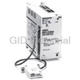
OMRON AUTOMATION SDV-SH10

Description
Voltage Sensor Detect Voltage 10V to 300V 4-Pin
SDV-SH10
Part Number
SDV-SH10
Price
Request Quote
Manufacturer
OMRON AUTOMATION
Lead Time
Request Quote
Category
Power » Power Accessories
Specifications
Manufacturer
Omron Automation
Manufacturers Part #
SDV-SH10
Industry Aliases
SDV-SH10
Sub-Category
Power Accessories
Factory Pack Quantity
1
Datasheet

Extracted Text
Voltage Sensor SDV CSM_SDV_DS_E_6_3 Overvoltage/Undervoltage Monitoring Relay for AC and DC Input • Detect overvoltages or undervoltages (switch select- able) from 4 mV to 300 V. Detect undercurrent, reverse current, or overcurrent in DC circuits using shunt (SDV-FL). Detect three-phase AC current for under and/or overcur- rent using current converter. Available in 7 supply voltage configurations. Single-function model with ON-delay, OFF-delay, or star- tup lock settings (SDV-FH@T). For the most recent information on models that have been certified for Select either AC or DC voltage input. safety standards, refer to your OMRON website. Polarity can be specified (SDV-FL) to enable easy re- verse current detection. Selectable reset value range from 2% to 30% of operat- ing value (SDV-F). LED operation indicator. UL/CSA approval (SDV-F@). Model Number Structure ■ Model Number Legend SDV-@@@@@ 123456 1. Voltage Sensor Note: Not possible for the SDV equipped with the timing function (SDV-FH@T). 2. Operation F: Single-function (overvoltage or undervoltage detection) D: Dual-function (overvoltage and undervoltage detection) 3. Operating Voltage Range L: 4 to 240 mV (DC input only) (For SDV-F only) M: 0.2 to 12 V (AC or DC input) H: 10 to 300 V (AC or DC input) 4, 5. Control Power Supply Voltage 2: 24 VDC 3: 48 VDC 4: 100/110 VDC 5: 125 VDC 51: 200/220 VDC (Single-function models) 6: 100/110 VAC 61: 120 VAC (Single-function models) 7: 200/220 VAC 71: 240 VAC (Single-function models) 6. Timing Function (SDV-FH Only (See Note)) None: Not provided T: Provided Note: SDV-FL and SDV-FM models can also be equipped with the timing function as a special specification. Ask your OMRON representative for details. 1 SDV SDV-SH @@@@ (Order Separately) 12345 1. Shunt (For SDV-FL Only) 2, 3, 4, 5. Rated Current Available Models Rated current Rated voltage Model Rated current Rated voltage Model 5 A 60 mV SDV-SH5 75 A 60 mV SDV-SH75 7.5 A SDV-SH7.5 100 A SDV-SH100 7.5 A 100 mV SDV-SH7.5 100MV 150 A SDV-SH150 10 A 60 mV SDV-SH10 200 A SDV-SH200 15 A SDV-SH15 300 A SDV-SH300 20 A SDV-SH20 500 A SDV-SH500 30 A SDV-SH30 750 A SDV-SH750 50 A SDV-SH50 1,000 A SDV-SH1000 Note: All the above listed shunts have an accuracy in the 1.0 class. Connecting Socket (Order Separately) Socket Applicable models Type Model SDV-F@@/-FH@T Front Connecting Socket 8PFA1 Back Connecting Socket PL08 SDV-D@@ Front Connecting Socket 14PFA Back Connecting Socket PL15 Ordering Information Single-function Models Overvoltage or Undervoltage Detection (Switch Selectable) Control power supply voltage Input DC DC or AC (selectable) Input voltage range 4 to 240 mV 0.2 to 12 V 10 to 300 V 24 VDC SDV-FL2 SDV-FM2 SDV-FH2 48 VDC SDV-FL3 SDV-FM3 SDV-FH3 100/110 VDC SDV-FL4 SDV-FM4 SDV-FH4 125 VDC SDV-FL5 SDV-FM5 SDV-FH5 200/220 VDC --- --- SDV-FH51 100/110 VAC SDV-FL6 SDV-FM6 SDV-FH6 120 VAC --- --- SDV-FH61 200/220 VAC SDV-FL7 SDV-FM7 SDV-FH7 240 VAC --- --- SDV-FH71 Dual-function Models Overvoltage and Undervoltage Detection Control power supply voltage Input: DC or AC (selectable) Input voltage range 0.2 to 12 V 10 to 300 V 24 VDC SDV-DM2 SDV-DH2 48 VDC SDV-DM3 SDV-DH3 100/110 VDC SDV-DM4 SDV-DH4 125 VDC SDV-DM5 SDV-DH5 100/110 VAC SDV-DM6 SDV-DH6 200/220 VAC SDV-DM7 SDV-DH7 240 VAC SDV-DM71 SDV-DH71 Note: 1. Inquire about production of models with 120- and 240-VAC control power supply. 2. Inquire about models with special processing for high-temperature, high-humidity applications. 3. The ripple factor must be 5% or less for DC power supplies. 2 SDV Single-function Models with Timing Function Control power supply voltage Input: DC or AC (selectable); input voltage range: 10 to 300 V Operating mode ON-delay OFF-delay Startup lock 24 VDC SDV-FH2T 48 VDC SDV-FH3T 100/110 VDC SDV-FH4T 125 VDC SDV-FH5T 200/220 VDC SDV-FH51T 100/110 VAC SDV-FH6T 120 VAC SDV-FH61T 200/220 VAC SDV-FH7T 240 VAC SDV-FH71T Note: Only SDV-FH voltage sensors can be manufactured with a timer. Specifications Single-function Models Overvoltage or Undervoltage Detection (Switch Selectable) Model Input voltage Selectable operating range Selectable reset value range Control power supply SDV-FL@ DC 4 to 240 mV 2% to 30% (related to 24, 48, 100/110, 125, 200/220 VDC (4 to 12 mV, 10 to 30 mV, operating value) (see note); 20 to 60 mV, 40 to 120 mV, 100/110, 200/220/240 VAC 80 to 240 mV) (50/60 Hz) SDV-FM@ DC or AC 0.2 to 12 V (selectable) (0.2 to 0.6 V, 0.5 to 1.5 V, 1 to 3 V, 2 to 6 V, 4 to 12 V) SDV-FH@ 10 to 300 V SDV-FH@T (10 to 30 V, 25 to 75 V, 50 to 150 V, 100 to 300 V) Note: Ripple is 5% max. with DC power supplies. Dual-function Models Overvoltage and Undervoltage Detection Model Input voltage Selectable operating range Reset value Control power supply Intermediate voltage of Dead band dead band voltage SDV-DM@ DC or AC 0.2 to 12 V 0.2 to 0.6 V 0.02 to 0.1 V Overvoltage: 24, 48, 100/110, 125 VDC; (selectable) (Intermediate voltage of 100/110, 200/220/240 VAC 0.5 to 1.5 V 0.05 to 0.25 V dead band + dead band (50/60 Hz) 1 to 3 V 0.1 to 0.5 V voltage) – (dead band volt- 2 to 6 V 0.2 to 1 V age x 2/3) min. Undervoltage: 4 to 12 V 0.4 to 2 V (Intermediate voltage of SDV-DH@ 10 to 300 V 10 to 30 V 1 to 5 V dead band – dead band 25 to 75 V 2.5 to 12.5 V voltage) + (dead band volt- age x 2/3) max. 50 to 150 V 5 to 25 V 100 to 300 V 10 to 50 V Note: 1. Inquire about production of models with 120- and 240-VAC control power supply. 2. The ripple factor must be 5% or less for DC power supplies. 3 SDV ■ Ratings Item SDV-FL@ SDV-FM@ SDV-FH@/FH@TSDV-DM@ SDV-DH@ Allowable continuous ±10 VDC ±150 VDC ±350 VDC ±150 VDC ±350 VDC input overvoltage range 150 VAC (±500 VDC for 1 min) 150 VAC (±500VDC for 1min) 350 VAC 350 VAC (500 VAC for 1 min) (500 VAC for 1 min) Input impedance 1 kΩ 50 kΩ 2,500 kΩ 50 kΩ 2,500 kΩ Control output SPDT SPST-NO and SPST-NC Rated load: 5 A at 220 VAC (cosφ = 1), 5 A at 24 VDC (cosφ = 1), 2 A at 220 VAC (cosφ = 0.4), 2 A at 24 VDC (L/R = 7 ms) Max. contact voltage: 250 VAC, 125 VDC Max. contact current: 5 A Max. switching capacity: 1,100 VA (cosφ = 1), 120 W (cosφ = 1), 440 VA (cosφ = 0.4), 48 W (L/R = 7 ms) Power consumption DC: 5 W max.; AC: 5 VA max. Ambient temperature –10 to 55°C (with no icing) Control supply voltage 24, 48, 100/110, 125, 200/220 VDC; DC operating voltage range: 80% to 130% of control power supply (see note) 100/110/120, 200/220/240 VAC (50/60 Hz); AC operating voltage range: 85% to 110% of control power supply Note: The impedance value is a reference value; actual values may vary. ■ Characteristics Item SDV-F@@ SDV-FH@TSDV-D@@ Operating value 100% operation for voltage setting Setting error Operating value: ±2% of operating value ±2% of intermediate voltage of dead band, (This is the ratio for the setting value.) ±1% of dead band voltage Reset value: ±7% of reset value (This is the ratio for the setting value.) Operating time 0.5 s max. (see note) Influence of temperature 0 to 40°C: 0 to 40°C: ±2% max. of operating value ±2% max. of dead band voltage (SDV-FL (operating value range: 4 to 12 mV) –10 to 0°C, 40 to 55°C: ±4% max. of operating value) ±4% max. of dead band voltage –10 to 0°C, 40 to 55°C: ±4% max. of operating value (SDV-FL (operating value range: 4 to 12 mV) ±8% max. of operating value) Influence of control power ±1% max. of operating value ±1% max. of dead band voltage DC operating voltage range: 80% to 130% DC operating voltage range: 80% to 130% AC operating voltage range: 85% to 110% AC operating voltage range: 85% to 110% Influence of frequency ±1% max. of operating value ±1% max. of dead band voltage (Input frequency changed from 10 to 500 Hz for AC in- put) Influence of waveform ±3% max. of operating value ±3% max. of dead band voltage (For commercial frequency, single-phase, full-wave AC input) Insulation resistance 10 MΩ min. (at 500 VDC) between the entire electric circuitry and external case, and between the input terminal and power terminal Dielectric strength 2,000 VAC for 1 min between the entire electric circuitry and external case, and between the input terminal and power terminal Impulse withstand voltage ±1.2 x 50 μs, 4,500 V between the entire electric circuitry and external case ±1.2 x 50 μs, 3,000 V between power terminals Vibration resistance Destruction: 10 to 25 Hz, 2-mm double amplitude (2G max.) for 2 hrs each in 3 directions Malfunction: 16.7 Hz, 1-mm double amplitude for 10 min each in 3 directions 2 Shock resistance Destruction: 294 m/s (30G) 2 Malfunction: 98 m/s (10G) Weight Approx. 290 g Approx. 350 g Approx. 310 g Note: Overvoltage: Operation when voltage is changed from 80% to 120% of the operating value. Undervoltage: Operation when voltage is changed from 120% to 80% of the operating value. 4 SDV Timing Function Item SDV-FH@T Setting time 0.5 to 30.0 s (see note) Operating time accuracy ±5% FS max. Setting error ±15% FS max. Reset time 5 s min. Influence of temperature ±10% FS max. Operating mode (set via DIP switch) ON-delay, OFF-delay, Startup lock Note: The time setting range when the startup lock is selected for the operating mode is approximately 1 to 30 s. Nomenclature SDV-D@ SDV-F@/-FH@T Operation Indicator (LED) Setting Intermediate The diagram on Setting Operating Setting Dead Voltage of Dead Band the right shows Value Band Voltage Function Sticker the SDV-FH6T when used for Voltage Multiplying undervoltage Factor Sticker detection for Operation Indicator DC input. Setting Reset Value Location of DIP switch to set operating modes Function Sticker Voltage Multiplying Factor Sticker Location of DIP switch to Setting Operating Time set operating modes The diagram above shows the SDV-DH3 when used for AC input Note: The SDV-F@ is not equipped with a time setting knob. in the range 100 to 300 V. 5 SDV Operation ■ Timing Charts Single-function Models Overvoltage Detection Undervoltage Detection Input Input Operating value Operating Reset value Reset value value ON Output relay ON OFF Output relay OFF Note The reset time must be 5 s or longer to ensure accuracy of the timing operation. Single-function Model with Timing Function SDV-FH@T ON-delay Overvoltage Detection Input Input Operating Operating value Reset value value Reset value Setting time Output relay ON Reset time Output relay OFF (5 s min.) Setting time Setting time Setting time ON-delay Undervoltage Detection Input Input Reset value Reset value Operating Operating value value Setting time Output relay ON ON OFF Output relay OFF Reset time (5 s min.) Setting time Setting time Setting time 6 SDV OFF-delay Overvoltage Detection Input Input Operating value Reset value Operating Reset value value Setting time Output relay ON OFF ON Output relay Reset time OFF (5 s min.) Setting time Setting time Setting time OFF-delay Undervoltage Detection Input Input Reset value Reset value Operating Operating value value Setting time ON ON Output relay Output relay OFF OFF Reset time (5 s min.) Setting time Setting time Setting time Startup Lock ON ON Power Power OFF OFF Reset time (5 s min.) Output operation Setting time Note: The output relays will be forced OFF from the control power supply is turned ON until the set time has expired. Dual-function Models SDV-D Input H Dead band voltage Intermediate voltage of Dead band voltage dead band L ON ON Undervoltage Overvoltage relay relay 7 SDV ■ Setting (Refer to Examples of Mode Settings for details on individual models.) Set the desired values using the DIP switch and setting knobs on the front panel. Opening the DIP Switch Cover Remove the cover of the compartment containing the DIP switch for various mode settings, and then set the DIP switch according to the SWITCH SELECTION table affixed to the side of the voltage sensor. Cover Cover Flat-blade screwdriver Flat-blade screwdriver Setting the DIP Switch Set the DIP switch on the front panel for the required functions, operation inputs, and voltages. Set the switch to the top for ON settings and to the bottom for OFF settings. • Function (SDV-F): Set to either overvoltage or undervoltage detection. Input: Set to either AC or DC input. Polarity (SDV-FL@ only): Set polarity or not to specify polarity. “8(+), 7(–)”: Use polarity as shown for pin number. “FREE”: Do not use polarity. Multiplying Factor: Set the voltage scale multiplying factor for the required operating voltage setting range. TIMER (SDV-FH@T): Select the timing function. Set ON-delay, OFF-delay, lock timer (start lock timer), or TIMER OFF. If TIMER OFF is set, the timing function will not be effective, and the single-function operation will be performed. Setting of Time (SDV-FH@T Only) Use the time setting knob to set the desired time. Closing the DIP Switch Cover Attach the cover to the compartment housing the DIP switch. Select the stickers for the settings that have been made and attach them to the cover. Setting Flowchart Select model based on operation and type of input. Single-function Model Dual-function Model Determine intermediate voltage of dead band and dead band Determine detection method, polarity setting, operating value, voltage. and reset value. Determine reset value according to dead band voltage. Obtain the PICK UP index scale value, HOLD index scale Obtain the BALANCE index scale value, BAND WIDTH index value, and voltage multiplying factor. scale value, and voltage multiplying factor. Set the knob and the DIP switch, and attach stickers. Set the knob and the DIP switch, and attach stickers. Set the desired operating mode for the SDV-FH@T. 8 SDV SDV-FL@ Switch Selection Table Accessory Labels Switch ON ● 1 2 3 4 5 6 OFF OVER ×4 mV POL FREE Function Under ● OVER Over 8 (+) ×10 mV POL7 (−) Polarity 8 (+) 7 (–) ● UNDER Free ×20 mV POL FREE Multiplying x 4 mV → UNDER factor ×40 mV 8 (+) x 10 mV → ● POL7 (−) x 20 mV → ● ×80 mV x 40 mV → ● x 80 mV → ● SDV-FM@ Switch Selection Table Accessory Labels Switch ON ● 2 3 1 4 5 6 OFF OVER ×0.2 V INPUT DC Function Under ● OVER Over ×0.5 V INPUT AC Input AC (20 to 500 Hz) ● UNDER ×1 V INPUT DC DC Multiplying x 0.2 V → UNDER ×2 V factor INPUT AC x 0.5 V → ● x 1 V → ● ×4 V x 2 V → ● x 4 V → ● SDV-FH@ Switch Selection Table Accessory Labels Switch ON ● 1 2 3 4 5 6 OVER OFF ×10 V INPUT DC Function Under ● OVER ×25 V Over INPUT AC Input AC (20 to 500 Hz) ● UNDER ×50 V DC INPUT DC Multiplying x 10 V → UNDER factor ×100 V x 25 V → ● INPUT AC x 50 V → ● x 100 V → ● Note: “NO USE” indicates that DIP switch setting is not required and the positions of these switches are irrelevant to the operation of the voltage sensor. 9 NO USE (see note) SDV SDV-FH@T Switch Selection Table Switch ON ● 1 2 3 4 5 6 7 8 9 10 Accessory Labels OFF OVER ×10 V Function Under ● INPUT DC Over OVER ×25 V INPUT AC Input AC (20 to 500 Hz) ● DC UNDER ×50 V INPUT DC Multiplying x 10 V → factor x 25 V → ● UNDER ×100 V INPUT AC x 50 V → ● x 100 V → ● Timer ON-delay → ● ● ● OFF-delay → ● ● Lock timer → ● Timer OFF → Note: “NO USE” indicates that DIP switch setting is not required and the positions of these switches are irrelevant to the operation of the voltage sensor. SDV-DM@ Switch Selection Table Accessory Labels Switch ON ● 1 2 3 4 5 OVER& OFF UNDER ×0.2 V INPUT DC Input AC (20 to ● OVER& 500 Hz) UNDER ×0.5 V INPUT AC DC Multiplying x 0.2 V → ×1 V factor x 0.5 V → ● x 1 V → ×2 V ● x 2 V → ● ×4 V x 4 V → ● SDV-DH@ Switch Selection Table Accessory Labels Switch ON ● 2 3 1 4 5 OVER& OFF UNDER ×10 V INPUT DC Input AC (20 to ● OVER& 500 Hz) UNDER ×25 V INPUT AC DC Multiplying x 10 V → ×50 V factor x 25 V → ● x 50 V → ● ×100 V x 100 V → ● Note: “NO USE” indicates that DIP switch setting is not required and the positions of these switches are irrelevant to the operation of the voltage sensor. 10 NO USE NO USE (see note) (see note) NO USE (see note) SDV ■ Examples of Mode Setting Example 1 For the single-function SDV-FH6, the setting method given below would be used to detect overvol- tages with a DC voltage input. The operating value is 15 V and the reset value is 12 V. Step 1. To set the detection method and type of input on the DIP switch. Turn OFF pin 1 (function) to specify overvoltage detection. SDV-F@@ Turn OFF pin 2 (input) to specify a DC input. Attach the OVER INPUT DC stickers. Step 2. To set the operating value according to the voltage multiplying factor and the PICK UP index scale value. Voltage multiplying factor setting: The voltage multiplying factor is selected according to the maximum and minimum factors and a sticker is attached. The calculation method is as follows: The PICK UP index scale value is between 1.0 and 3.0, so calculate the voltage multiplying factor for both 1.0 and 3.0. 15 V (Operating value)/1 (PICK UP index scale value) = 15 (Maximum multiplying factor) 15 V (Operating value)/3 (PICK UP index scale value) = 5 (Minimum multiplying factor) In this example, pins 3 to 5 are turned OFF and the x10V sticker is attached. PICK UP index scale value setting: The calculation method is as follows (X = index scale): 10 (Voltage multiplying factor) x X = 15 V (Operating value) Therefore, X = 1.5 Turn the PICK UP knob to 1.5. Step 3. To set the reset value (Y = HOLD index scale value): Calculate the HOLD percentage as follows: 12 V (reset value) = 15 V (operating value) x (1 − Y) Therefore, Y = 0.2 Set the HOLD knob to 20 (%). Example 2 For the single-function SDV-FH6T, the setting method given below would be used to detect undervol- tages with a DC voltage input. The operating value is 20 V and the reset value is 20.4 V. An ON-delay operation is specified and the setting time is 30 s. Step 1. To set the detection method and type of input on the DIP switch. SDV-FH@T Turn ON pin 1 (function) to specify undervoltage detection. Turn OFF pin 2 (input) to specify a DC input. Attach the UNDER INPUT DC stickers. Step 2. To set the operating value according to the voltage multiplying factor and the PICK UP index scale value. Voltage multiplying factor setting: The multiplying factor is selected according to the maxi- mum and minimum factors and a sticker is attached. The calculation method is as follows: The PICK UP index scale value is between 1.0 and 3.0, so calculate the voltage multiplying factor for both 1.0 and 3.0. 20 V (Operating value)/1 (PICK UP index scale value) = 20 (Maximum multiplying factor) 20 V (Operating value)/3 (PICK UP index scale value) = 6.7 (Minimum multiplying factor) In this example, pins 3 to 5 are turned OFF and the x10V sticker is attached. PICK UP index scale value setting: The calculation method is as follows (X = index scale): 10 (Voltage multiplying factor) x X = 20 V (Operating value) Therefore, X = 2 Turn the PICK UP knob to 2.0. Step 3. To set the reset value (Y = HOLD index scale value): Calculate the HOLD percentage as follows: 20.4 V (reset value) = 20 V (operating value) x (1 + Y) Therefore, Y = 0.02 Set the HOLD knob to 2 (%). Step 4. To set setting time and operating mode. Set the time setting knob to 30 s and turn the pins 7 to 9 ON to specify ON-delay operation. 11 SDV Example 3 For the dual-function SDV-DH3, the setting method given below would be used to detect over and undervoltage with an AC voltage input. The intermediate voltage of dead band is 250 V and the dead band voltage is 20 V. Step 1. To set the detection method and type of input on the DIP switch. SDV-D@@ Turn ON pin 1 (input) to specify a AC input. Attach the OVER and UNDER INPUT AC stickers. Step 2. To set the intermediate voltage of dead band according to the BALANCE index scale value and the voltage multiplying factor. Voltage multiplying factor setting: The voltage multiplying factor is selected according to the maximum and minimum factors and a sticker is attached. The calculation method is as fol- lows: The BALANCE index scale value is between 1.0 and 3.0, so calculate the voltage multiply- ing factor for both 1.0 and 3.0. 250 V (Intermediate voltage of dead band)/1 (BALANCE index scale value) = 250 (maximum multiplying factor) 250 V (Intermediate voltage of dead band)/3 (BALANCE index scale value) = 83.3 (maximum multiplying factor) In this example, pins 2 and 3 are turned OFF and pins 4 is turned ON, and the x100V sticker is attached. BALANCE index scale value setting: The calculation method is as follows for the BALANCE index scale value (X = index scale): 100 (Voltage multiplying factor) x X = 250 V (intermediate voltage of dead band) Therefore, X = 2.5 Turn the BALANCE knob to 2.5. Step 3. To set dead band voltage according to the voltage multiplying factor and BAND WIDTH index scale value. BAND WIDTH index scale value setting: Z (BAND WIDTH index scale value) x 100 V (voltage multiplying factor) = 20 V (dead band voltage) Therefore, Z = 0.2 Set the DEAD WIDTH knob to 0.2. Step 4. Reset value for each detection setting: Automatically set according to the dead band voltage setting. Reset values are calculated for overvoltage detection and undervoltage detection. Overvoltage detection: Reset value = (250 V + 20 V) − (20 V x 2/3) = 256.7 min. Undervoltage detection: Reset value = (250 V − 20 V) + (20 V x 2/3) = 243.3 max. ■ Shunts (Order Separately) Characteristics SDV-SH5A (Rated Current: 5 A) A shunt is a resistor to convert a DC current into a DC voltage. Use the shunt in combination with SDV-FL to detect undercurrent, reverse current and overcurrent in DC circuits. Note: Select a shunt whose rated current is more than 120% of the current normally flowing in a circuit. The characteristics of the Shunt rated at 60 mV shunt may change or fusing of a resistor element may occur if an overload that is 1,000% of the rated current is applied. 60 Therefore, determine the rated current of the shunt to be used, by taking the circuit conditions into account. 5 Input current (A) 12 Output voltage (mV) SDV ■ Application Example Current Detection Using the Shunt (SDV-FL) Overload Detection (B) Overload Detection (A) (+) (−) SDV-SH DC power SDV-SH Power shunt supply for or M _ shunt supply distribution board DC motor (−) (+) (−) SDV-FL SDV-FL (with or without polarity) (without polarity) (+) Example: Overload detection in equipment such as a motor in a Example: Overload detection in a distribution switch rolling mill when the polarity of the applied voltage to board installed in a power substation. the motor is reversed. Reverse Current Detection (A) Reverse Current Detection (B) 4 to 20mA SDV-SH Power supply DC power for transmitter shunt M _ supply 10 Ω or more DC motor Quantity of low, airflow, wattage, etc. (+) (+) SDV-FL (with or without polarity) (−) SDV-FL (−) (with polarity) Example: Detection of an output current from a transmitter on Example: Detection when a DC motor is used a control panel. as a generator (or a generator is used as a motor). Voltage Detection (SDV-FM/FH/FH@T/-DM/-DH) Operation Lock Due to Voltage Drop (Alarm) Voltage Regulation 3 dia. Machine Distribu- Thyristor or equip- tion power ment switch supply board Command signal for operation (+) Command lock signal for regulation SDV-FH/SDV-FH@T with ON-delay operation (undervoltage detection) SDV-DH (−) Example: Function lock due to voltage drop in a machine or Example: Voltage regulation of a power supply unit in the dis- equipment (alarm). tribution switchboard installed in a power substation. 13 Distribution switchboard Transmitter SDV Emergency Power Supply (e.g. Standard Power Receiving/Distributing Facility) Non-utility generator Engine G Voltage regula- tion (rotation control) Detection of power failure SDV-DH Exciter Drive command (Starts/Stop) SDV-FH (undervol- tage detection) Power supply Detection of power failure or trans- former trouble (for the DC lighting command in emergency illumination) SDV-FH (undervoltage detection) Detection of battery overdischarge SDV-FH/SDV-FH@T with ON-delay operation (undervoltage detection) Distribution board for general illumination Detection of partial power failure (for the lighting command in emergency illumination) SDV-FH (undervoltage detection) Distribution board for Emergency illumination emergency illumination output 14 SDV Three-phase AC Current Detection Using Current Converter SET Current Converter SDV-DH SDV-FH SDV-FH@T SDV-FM Example: Machine motor control, overload detection, undercurrent detection. Current Converters (Order Separately) Model Current range SET-3A 1 to 80 A SET-3B 64 to 160 A Three-phase AC Current Detection with Startup Lock Operation (When Using Same Power Supply for Motor and Control Power Supply) SET Current Converter Control power supply SDV-FH@T Voltage Monitoring in Rectifiers (Chargers) with ON-delay Operation Example: To detect only overvoltage and not detect voltages for instantaneous load changes (ON/OFF). Rectifier SDV-FH@T overvoltage detection SDV-FH@T undervoltage detection Note: Detection of excessive or insufficient charge in rectifiers (chargers). 15 Load Load SDV ■ Q&A Q: What is necessary to detect undervoltages when using the same power supply for the input voltage and the control power supply? SDV-F (undervoltage detection) A: The NO contact of the output relay is used for undervoltage detection. Even if the control voltage drops to 85% of the rated voltage (AC power), the operation of the relay can be maintained. Set the mode setting on the DIP switch to overvoltage detection and set the reset value to the value to be detected. Set the operating value of the SDV to a value higher than the reset value. Q: Will the SDV be damaged if the input setting (AC/DC) is incorrect. If not, what will happen? A: The SDV will not be damaged, but the operating value and reset value will not be accurate. These values will be about 10% less than the set values if DC is input for an AC setting and about 10% off to the positive side if AC is input for a DC setting. Q: Can the negative pole of a DC voltage be input to the SDV? A: Yes. An absolute rectifier circuit is used in the SDV-F to enable negative pole input. The SDV-FL has a polarity setting, which can be set to (+)(–) to disable operation with negative voltages. Positive/Negative settings cannot be used for the dual-function SDV-D even if the intermediate voltage of dead band is set to 0. Negative inputs can- not be used for the SDV-D. Q: Is instantaneous detection faster than 0.5 s possible? A: Use the S87A Power Interruption Detector for instantaneous detection (10 ms or 20 ms). 16 Load SDV Dimensions Note: All units are in millimeters unless otherwise indicated. ■ Main Body SDV-F@@/SDV-FH@T Connecting Socket 3.5 5 SDV-F 91 72 119 100 SDV-F 16 8PFA1 (order separately) 7 60 89 8.5 PL08 (order separately) 100 SDV-D@@ 3.5 5 79 60 SDV-D 128.5 100 SDV-D 72 7 89 8.5 16 100 14PFA (order separately) PL15 (order separately) ■ Shunts SDV-SH5 to SDV-SH50 (60-mV Rating) SDV-SH75 to SDV-SH200 (60-mV Rating) 140 A 120 B 25 C D 10.5 dia. E G 33 18 F 6 5.5 5.5 dia. dia. Current terminal: M8 screw Current terminal: M6 screw Voltage terminal: M4 screw Voltage terminal: M4 screw Model A B C D E F G SDV-SH75 140 120 25 10.5 6 18 36 SDV-SH100 140 120 25 10.5 6 18 36 SDV-SH150 140 120 25 10.5 6 18 43 SDV-SH200 140 120 25 10.5 6 18 43 17 SDV SDV-SH300/-SH500 (60-mV Rating) SDV-SH750/-SH1000 (60-mV Rating) A A B B C C 5 E E D D Current terminal: M12 screw Current terminal: M10 screw (SDV-SH300), Voltage terminal: M5 screw M12 screw (SDV-SH500) Voltage terminal: M4 screw Model A B C D E SDV- 175 45 130 15 30 Model A B C D E Resistor SH750 SDV- 130 30 110 4 36 4 SDV- 175 60 135 18 30 SH300 SH1000 SDV- 160 40 120 6 41 5 SH500 Note: Inquire about models with a rated current of 1,500 A or larger. ■ Accessories (Order Separately) Front Connecting Socket 8PFA1 Terminal Arrangement Eight, M3.5 x 7 (Top View) sems Two, 4.5-dia. holes 93 max. 130 max. Mounting Holes Two, M4 or 4.5-dia. holes 51 max. 24 max. 14PFA Terminal Arrangement (Top View) Fourteen, M3.5 x 7 sems Two, 4.5-dia. holes 81 max. 118 max. Mounting Holes Two, M4 or 4.5-dia. holes 72 max. 33.5 max. 18 SDV Back Connecting Socket (Solder Terminal) PL08 Terminal Arrangement Mounting Holes (Bottom View) Two, 2-dia. holes Two, 3.5-dia. or 50.5 max. 30 dia. two, M3 socket mounting holes 31-dia. hole 35 max. Approx. 20.5 PL15 Terminal Arrangement (Bottom View) Two, 2-dia. holes 66 max. 41 max. 22 max. Mounting Holes 45 max. Two, M3 or two, 3.5-dia. voltage sensor mounting holes Two, M3 or Two, 3.5-dia. socket mounting holes 42-dia. hole Mounting Track PFP-100N PFP-50N PFP-100N2 16 7.3+0.15 4.5 4.5 27 29.2 27+0.15 35+0.3 24 35+0.3 15 25 25 25 25 15 25 25 15 25 25 1 1.5 1 15 (5)* 10 10 10 10 1,000 (500)* 1,000 *PFP-50N Spacers End Plates PFP-S PFP-M 16 M4 spring 10 5 12 washer 6.2 1.8 1 35.5 35.3 34.8 50 44.3 1.8 11.5 1.3 M4 x 8 pan 4.8 head screw 16.5 19 SDV Installation ■ Internal Circuit Input and power supply circuits are electrically isolated as protection against mutual interference. SDV-F@@/SDV-FH@T Range selector switches SW9 AC/DC selector VR switch SW2 (see note 4) SW6 SW5 SW4 SW3 Polarity selector switch (SW2) (see note 3) SW7 8 Input 7 SW1 To Overvoltage/ each Undervoltage 2 circuit Power selector switch Power Chopper 5 supply supply SW1 circuit circuit SW8 1 DC Power supply circuit 4 X/c To X each 2 Note: The SDV-FH@T contains 3 Power circuit Power supply supply the circuit outlined with the Output relay circuit dotted line. 1 AC Power supply circuit Note: 1. There is no polarity setting for the SDV-FM or SDV-FH/-FH@T. 2. There is no power supply polarity setting when using a DC control power supply for the SDV. 3. The polarity selection switch (SW2) is on the SDV-FL. 4. The AC/DC switch (SW2) is on the SDV-FM and SDV-FH/-FH@T. SDV-D Output relay for Range selector switches overvoltage detection XH AC/DC selector switch SW1 SW5 SW4 SW3 SW2 15 Input Output relay for 10 undervoltage detection 12 XL/a XL To 5 each 2 circuit Power Chopper Power supply 4 supply circuit XL/b circuit 1 3 DC Power supply circuit 6 To XH/a each 2 7 circuit Power Power supply supply 8 circuit 1 XH/b AC Power supply circuit 9 Note: 1. There is no power supply polarity setting when using a DC control power supply for the SDV. 2. There is no polarity setting for DC inputs. 20 rectifier circuit Absolute value rectifier circuit Amplifier circuit Amplifier circuit Operating value setting circuit Output relay for Smoothing overvoltage circuit detection Smoothing circuit Addition circuit Releasing value Reference Comparator setting circuit voltage circuit circuit Comparator Reference Comparator Reference voltage circuit voltage circuit circuit(High) circuit(Low) Power circuit Power circuit Inverter circuit Power circuit Startup lock reference voltage circuit Buffer circuit Buffer circuit Inverter circuit Quick charge/ discharge circuit Timer time setting circuit Reference Comparator voltage circuit circuit Dear band setting circuit Absolute value SDV Safety Precautions Approximately 0.5 s is required for operation. When confirming the operating value, gradually change the input voltage while checking the value. Power supply voltage fluctuations and the ambient operating temper- ature must be maintained within the allowable ranges. Be particularly careful not to apply an overvoltage beyond the specified range for the voltage detection. Do not use the SDV in locations subject to corrosive or explosive gases. The SDV cannot be used to detect momentary power interruptions because of its response time. Use the S87A to detect momentary power interruptions. S87A Power Interruption Detector An SDV cannot be used with a circuit containing thyristors, or VVVF inverters, because these elements can change the output waveform to the point that the SDV will malfunction. Mounting When mounting with the PL08 or PL15 Back Connection Socket, insert the Socket into a 1- to 4-mm panel from the back and secure it with screws. Do not mount the SDV until the Socket has been mounted firmly. Be sure that the key groove on the Socket is mounted on the bottom, and also secure the SDV to the panel with screws. When mounting with the 8PFA or 14PFA Back Connection Socket, insert the SDV into the Socket and secure it with the hooks. Leave approximately 30 mm or more between Sockets to allow enough space for the hooks. When mounting more than one SDV, allow at least 30 mm or more between them. ALL DIMENSIONS SHOWN ARE IN MILLIMETERS. To convert millimeters into inches, multiply by 0.03937. To convert grams into ounces, multiply by 0.03527. In the interest of product improvement, specifications are subject to change without notice. 21 Terms and Conditions Agreement Read and understand this catalog. Please read and understand this catalog before purchasing the products. Please consult your OMRON representative if you have any questions or comments. Warranties. (a) Exclusive Warranty. Omron’s exclusive warranty is that the Products will be free from defects in materials and workmanship for a period of twelve months from the date of sale by Omron (or such other period expressed in writing by Omron). Omron disclaims all other warranties, express or implied. (b) Limitations. OMRON MAKES NO WARRANTY OR REPRESENTATION, EXPRESS OR IMPLIED, ABOUT NON-INFRINGEMENT, MERCHANTABILITY OR FITNESS FOR A PARTICULAR PURPOSE OF THE PRODUCTS. BUYER ACKNOWLEDGES THAT IT ALONE HAS DETERMINED THAT THE PRODUCTS WILL SUITABLY MEET THE REQUIREMENTS OF THEIR INTENDED USE. Omron further disclaims all warranties and responsibility of any type for claims or expenses based on infringement by the Products or otherwise of any intellectual property right. (c) Buyer Remedy. Omron’s sole obligation hereunder shall be, at Omron’s election, to (i) replace (in the form originally shipped with Buyer responsible for labor charges for removal or replacement thereof) the non-complying Product, (ii) repair the non-complying Product, or (iii) repay or credit Buyer an amount equal to the purchase price of the non-complying Product; provided that in no event shall Omron be responsible for warranty, repair, indemnity or any other claims or expenses regarding the Products unless Omron’s analysis confirms that the Products were properly handled, stored, installed and maintained and not subject to contamination, abuse, misuse or inappropriate modification. Return of any Products by Buyer must be approved in writing by Omron before shipment. Omron Companies shall not be liable for the suitability or unsuitability or the results from the use of Products in combination with any electrical or electronic components, circuits, system assemblies or any other materials or substances or environments. Any advice, recommendations or information given orally or in writing, are not to be construed as an amendment or addition to the above warranty. See http://www.omron.com/global/ or contact your Omron representative for published information. Limitation on Liability; Etc. OMRON COMPANIES SHALL NOT BE LIABLE FOR SPECIAL, INDIRECT, INCIDENTAL, OR CONSEQUENTIAL DAMAGES, LOSS OF PROFITS OR PRODUCTION OR COMMERCIAL LOSS IN ANY WAY CONNECTED WITH THE PRODUCTS, WHETHER SUCH CLAIM IS BASED IN CONTRACT, WARRANTY, NEGLIGENCE OR STRICT LIABILITY. Further, in no event shall liability of Omron Companies exceed the individual price of the Product on which liability is asserted. Suitability of Use. Omron Companies shall not be responsible for conformity with any standards, codes or regulations which apply to the combination of the Product in the Buyer’s application or use of the Product. At Buyer’s request, Omron will provide applicable third party certification documents identifying ratings and limitations of use which apply to the Product. This information by itself is not sufficient for a complete determination of the suitability of the Product in combination with the end product, machine, system, or other application or use. Buyer shall be solely responsible for determining appropriateness of the particular Product with respect to Buyer’s application, product or system. Buyer shall take application responsibility in all cases. NEVER USE THE PRODUCT FOR AN APPLICATION INVOLVING SERIOUS RISK TO LIFE OR PROPERTY OR IN LARGE QUANTITIES WITHOUT ENSURING THAT THE SYSTEM AS A WHOLE HAS BEEN DESIGNED TO ADDRESS THE RISKS, AND THAT THE OMRON PRODUCT(S) IS PROPERLY RATED AND INSTALLED FOR THE INTENDED USE WITHIN THE OVERALL EQUIPMENT OR SYSTEM. Programmable Products. Omron Companies shall not be responsible for the user’s programming of a programmable Product, or any consequence thereof. Performance Data. Data presented in Omron Company websites, catalogs and other materials is provided as a guide for the user in determining suitability and does not constitute a warranty. It may represent the result of Omron’s test conditions, and the user must correlate it to actual application requirements. Actual performance is subject to the Omron’s Warranty and Limitations of Liability. Change in Specifications. Product specifications and accessories may be changed at any time based on improvements and other reasons. It is our practice to change part numbers when published ratings or features are changed, or when significant construction changes are made. However, some specifications of the Product may be changed without any notice. When in doubt, special part numbers may be assigned to fix or establish key specifications for your application. Please consult with your Omron’s representative at any time to confirm actual specifications of purchased Product. Errors and Omissions. Information presented by Omron Companies has been checked and is believed to be accurate; however, no responsibility is assumed for clerical, typographical or proofreading errors or omissions. 2013.8 In the interest of product improvement, specifications are subject to change without notice. OMRON Corporation Industrial Automation Company http://www.ia.omron.com/ (c)Copyright OMRON Corporation 2013 All Right Reserved.
Frequently asked questions
How does Electronics Finder differ from its competitors?

Is there a warranty for the SDV-SH10?
Which carrier will Electronics Finder use to ship my parts?
Can I buy parts from Electronics Finder if I am outside the USA?
Which payment methods does Electronics Finder accept?
Why buy from GID?

Quality
We are industry veterans who take pride in our work

Protection
Avoid the dangers of risky trading in the gray market

Access
Our network of suppliers is ready and at your disposal

Savings
Maintain legacy systems to prevent costly downtime

Speed
Time is of the essence, and we are respectful of yours
Related Products
C500 BACKUP BATTERY 3G2A9-BAT08
Controller F3SXEL1D1R2
Controller F3SXEL2D1
Solid State Relays - Industrial Mount SOLID STATE RELAY G3PX-220EC-CT10
Voltage Sensor Detect Voltage 10V to 300V 4-Pin SDVFH61
Voltage Sensor Detect Voltage 10V to 300V 4-Pin SDV-SH15
Request a Quote

The quote request has been received
Close

Facing challenges or have inquiries? Feel free to contact us!
Call Us +1-469-283-2440
What they say about us
FANTASTIC RESOURCE
One of our top priorities is maintaining our business with precision, and we are constantly looking for affiliates that can help us achieve our goal. With the aid of GID Industrial, our obsolete product management has never been more efficient. They have been a great resource to our company, and have quickly become a go-to supplier on our list!
Bucher Emhart Glass
EXCELLENT SERVICE
With our strict fundamentals and high expectations, we were surprised when we came across GID Industrial and their competitive pricing. When we approached them with our issue, they were incredibly confident in being able to provide us with a seamless solution at the best price for us. GID Industrial quickly understood our needs and provided us with excellent service, as well as fully tested product to ensure what we received would be the right fit for our company.
Fuji
HARD TO FIND A BETTER PROVIDER
Our company provides services to aid in the manufacture of technological products, such as semiconductors and flat panel displays, and often searching for distributors of obsolete product we require can waste time and money. Finding GID Industrial proved to be a great asset to our company, with cost effective solutions and superior knowledge on all of their materials, it’d be hard to find a better provider of obsolete or hard to find products.
Applied Materials
CONSISTENTLY DELIVERS QUALITY SOLUTIONS
Over the years, the equipment used in our company becomes discontinued, but they’re still of great use to us and our customers. Once these products are no longer available through the manufacturer, finding a reliable, quick supplier is a necessity, and luckily for us, GID Industrial has provided the most trustworthy, quality solutions to our obsolete component needs.
Nidec Vamco
TERRIFIC RESOURCE
This company has been a terrific help to us (I work for Trican Well Service) in sourcing the Micron Ram Memory we needed for our Siemens computers. Great service! And great pricing! I know when the product is shipping and when it will arrive, all the way through the ordering process.
Trican Well Service
GO TO SOURCE
When I can't find an obsolete part, I first call GID and they'll come up with my parts every time. Great customer service and follow up as well. Scott emails me from time to time to touch base and see if we're having trouble finding something.....which is often with our 25 yr old equipment.
ConAgra Foods