

 Manufacturers
OMRON ELECTRONIC COMPONENTS 2SMPP03
Description
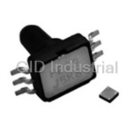
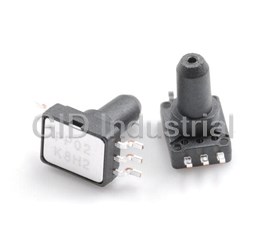
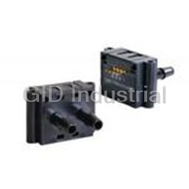
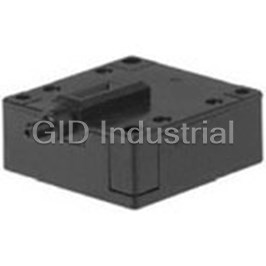
Pressure Sensor -50kPa to 50kPa Gage 6-Pin SOP Module
Part Number
2SMPP03
Price
Request Quote
Manufacturer
OMRON ELECTRONIC COMPONENTS
Lead Time
Request Quote
Category
Sensors and Transducers » Board Mount Pressure Sensor
Specifications
Manufacturer
Omron Electronic Components
Manufacturers Part #
2SMPP03
Lead Time
18 Week Lead Time
Industry Aliases
2SMPP03
Sub-Category
Board Mount Pressure Sensors
Factory Pack Quantity
112
Datasheet

Extracted Text
2SMPP-03 MEMS Gauge Pressure Sensor MEMS Gauge Pressure Sensor Featuring Small Size and Low Power Consumption • Superior electrical characteristics at -50 kPa to 50 kPa pressure range. Offset voltage of -2.5±4.0 mV Span voltage of 42.0±5.5 mV (At rated pressure 50 kPa, 100 µADC Current supply) • Small package 6.1 × 4.7 × 8.2 mm (L × W × H). • Good temperature dependency at 0 to 85°C, at rated pressure 0 to 50 kPa Temp. influence of span of ±3.0%FS Temp. influence of offset of ±5.0%FS (100 µADC Current supply) • Rated power consumption of 0.2 mW RoHS Compliant Refer to the Safety Precautions on page 7. Ordering Information Standard Models with Surface mount package Model Classification Structure Packaging MOQ (Minimum Order Quantity) 2SMPP-03 Bottom Port Type SOP Plastic sleeve 112 pcs/ 1 sleeve Terminal Arrangement Connection Diagram ➅ Icc ➀ Vout (+) 5 6 ➁ Non Connected ➄ N-sub + ➃ Vout (−) ➂ GND R2 R1 Output voltage Constant current 1 4 − source R3 R4 3 Note: If necessary, add a variable resistor below the GND pin (3). The NC pin (2) must be secured to the circuit board. 1 2SMPP-03 2SMPP-03 MEMS Gauge Pressure Sensor Application Examples • Home appliance • Air movement control • Level indicators • Leak detection • Pressure controller Specifications ■ Ratings Item 2SMPP-03 Type of pressure Gauge pressure Sensing method Piezoresistance Pressure medium Air Driving method Constant current drive Drive current 100 µADC Pressure range -50 to 50 kPa Withstand pressure -80 to 120 kPa Absolute maximum current 200 µADC max. Ambient operating temperature -10 to 100°C (with no icing and condensation) Ambient operating humidity 10 to 95%RH (with no icing and condensation) Ambient storage temperature -40 to 120°C (with no icing and condensation) Ambient storage humidity 10 to 95%RH (with no icing and condensation) Weight 0.17 g Note: 1. The above values are initial values measured at ambient temperature condition of 23°C. Note: 2. Please avoid caustic gases. 2 2SMPP-03 2SMPP-03 MEMS Gauge Pressure Sensor Characteristics ■ Operating characteristics Positive pressure (at rated pressure 0 to 50 kPa) Item Min. Typ. Max. Unit Supply current - 100 - µADC Bridge resistance 18.0 20.0 22.0 kohm Operating pressure range 0 - 50 kPa Offset voltage -6.5 -2.5 1.5 mV Span voltage 36.5 42.0 47.5 mV Non-linearity 0.3 0.8 1.3 %FS Pressure hysteresis -0.2 0.0 0.2 %FS Temperature influence of span voltage at 0°C -1.0 1.0 3.0 %FS Temperature influence of span voltage at 50°C -2.1 -0.1 1.9 %FS Temperature influence of span voltage at 85°C -2.0 1.0 4.0 %FS Temperature influence of offset voltage at 0°C -4.0 -1.0 2.0 %FS Temperature influence of offset voltage at 50°C -2.0 1.0 4.0 %FS Temperature influence of offset voltage at 85°C -3.0 2.0 7.0 %FS Negative pressure (at rated pressure 0 to -50 kPa) Item Min. Typ. Max. Unit Supply current - 100 - µADC Bridge resistance 18.0 20.0 22.0 kohm Operating pressure range -50 - 0 kPa Offset voltage -6.5 -2.5 1.5 mV Span voltage -48.5 -43.0 -37.5 mV Non-linearity -0.3 0.2 0.7 %FS Pressure hysteresis -0.2 0.0 0.2 %FS Temperature influence of span voltage at 0°C -1.2 0.8 2.8 %FS Temperature influence of span voltage at 50°C -1.9 0.1 2.1 %FS Temperature influence of span voltage at 85°C -1.8 1.2 4.2 %FS Temperature influence of offset voltage at 0°C -4.0 -1.0 2.0 %FS Temperature influence of offset voltage at 50°C -2.0 1.0 4.0 %FS Temperature influence of offset voltage at 85°C -3.0 2.0 7.0 %FS Note: 1. The above values are initial values. Note: 2. Ambient temperature condition: 23°C without Temperature property. Note: 3. The above values are operated at 100 µADC Note: 4. The above values are operated at 0 to 50 kPa, and 0 to -50 kPa. Note: 5. Offset voltage is defined as the output voltage at 0 kPa rated pressure. Note: 6. Positive span voltage is defined as the algebraic difference between the output voltage at 50 kPa rated pressure and the output voltage at 0 kPa rated pressure. Note: 7. Negative span voltage is defined as the algebraic difference between the output voltage at -50 kPa rated pressure and the output voltage at 0 kPa rated pres- sure. Note: 8. Hysteresis is defined as follows, In case of positive pressure: {The output voltage difference at 0 kPa before and after a pressure cycle (0 to 50 to 0 kPa)} / (span voltage) × 100 [%FS]. In case of negative pressure: {The output voltage difference at 0 kPa before and after a pressure cycle (0 to -50 to 0 kPa)} / (span voltage) × 100 [%FS]. Note: 9. Temperature influence of span voltage is defined as follows, {Span voltage at 0°C. - span voltage at 25°C. } / span voltage at 25°C. × 100 [%FS] {Span voltage at 50°C. - span voltage at 25°C. } / span voltage at 25°C. × 100 [%FS] {Span voltage at 85°C. - span voltage at 25°C. } / span voltage at 25°C. × 100 [%FS] Note: 10.Temperature influence of offset voltage is defined as follows, {Offset voltage at 0°C. - offset voltage at 25°C. } / span voltage at 25°C. × 100 [%FS] {Offset voltage at 50°C. - offset voltage at 25°C. } / span voltage at 25°C. × 100 [%FS] {Offset voltage at 85°C. - offset voltage at 25°C. } / span voltage at 25°C. × 100 [%FS] Environment characteristics Item 2SMPP-03 Destruction 10 to 500 Hz 10 G Vibration Resistance Malfunction 10 to 500 Hz 10 G Destruction 15 G Shock Resistance Malfunction 15 G Life Expectancy 100,000 Operations min. (0 to 75 kPa) ESD 1,000 V (Human body model) Package Material PPS (Polyphenylenesulfide) 3 2SMPP-03 2SMPP-03 MEMS Gauge Pressure Sensor Example of Application Circuit for MEMS Pressure Sensor VDD Constant current circuit unit Amplifier circuit unit Pressure + + − Sensor − − + Vout − + (1) The pressure sensor is designed to convert a voltage by means of constant current drive. (2) Please amplifier the output voltage of the pressure sensor by using the amplifying circuit if necessary. Engineering Data (for Reference) ■ Output Characteristics Rated Pressure vs. Output Voltage 40 30 20 10 0 –10 –20 –30 –40 –50 –50 –40 –30 –20 –10 0 10 20 30 40 50 Rated Pressure (kPa) Note: 1. Ambient temperature condition: 23°C. Note: 2. Drive current: 100 µA Note: 3. These output voltage characteristics are measured with tester without a mounting board. Note: 4. The output voltage characteristics may be influenced by the mounting board. Be sure to check operation including durability in actual equipment before use. 4 2SMPP-03 Output voltage (mV) 2SMPP-03 MEMS Gauge Pressure Sensor Temperature influence of Span voltage (at 0 to 50 kPa) Temperature influence of Offset voltage (at 0 kPa) 2 3 2.5 1.5 2 1.5 1 1 0.5 0.5 0 0 –0.5 –1 –0.5 –1.5 –2 –1 –10 0 10 20 30 40 50 60 70 80 90 –10 0 10 20 30 40 50 60 70 80 90 Temperature (˚C) Temperature (˚C) Note: 1. Measured points are 0°C, 25°C, 50°C and 85°C at 0 to 50 kPa. Note: 2. Drive current: 100 µA Note: 3. These output voltage characteristics are measured with tester without a mounting board. Note: 4. The output voltage characteristics may be influenced by the mounting board. Be sure to check operation including durability in actual equipment before use. Pressure Cycle Range ( 0 to 75 kPa) 1 1 0.5 0.5 0 0 –0.5 –0.5 –1 –1 0 25,000 50,000 75,000 100,000 0 25,000 50,000 75,000 100,000 Pressure cycle Pressure cycle Note: 1. Tested temperature condition: 25°C 5 Note: 2. Number of pressure cycle time: 1 × 10 Note: 3. Rated cycle pressure: 0 to 75 kPa Note: 4. These output voltage characteristics are measured with tester without a mounting board. 5 Offset voltage range (%FS) Temp. Influence of Positive Span Voltage (%FS) Span voltage range (%FS) Temp. Influence of Offset Voltage (%FS) 2SMPP-03 2SMPP-03 MEMS Gauge Pressure Sensor Dimensions Note: All units are in millimeters unless otherwise indicated. 4.75 4.10 0.25±0.05 3#1 3.80 dia. 0.62 dia. 6.15 9.85 3.20 5.50 4-R0.50 46 1.27 0.40 1.27 x 2 = 2.54 1.00 2.00 1.50 2.80 1.00 (1.10) 4.75 0.80 1.80 dia. 2.60 dia. Pin Diagram (Top Surface of Sensor) Atmospheric pressure hole 1 Vout (+) 6 Icc 2 NC 5 N-sub 3 GND 6 Vout (-) Markings Recommended Pad Dimensions 5.45 0.75 11.05 0.10 8.75 4.00 dia. 0.90 1.27 1.125 PP 0 3 4.05 1.125 0.45 5 6 7 8 0.60 2.30 (0.90) 1.65 1.65 Lot No. (1.075) 3.30 Note: Unless otherwise specified, the tolerance for all of the above drawings is ±0.3 mm. 6 2SMPP-03 A 2SMPP-03 MEMS Gauge Pressure Sensor Safety Precautions Precautions for Correct Use Handling the Sensor (4) Keep in an appropriate temperature and humidity condition (1) Only air can be used as pressure media on the products specified as directly. It is prohibited to use pressure media including cor- Temperature : 5 to 30°C , Humidity : 40 to 60%. rosive gases (e.g. organic solvents gases, sulfur dioxide and (5) As the lead is plated with silver, there is a possibility of being hydrogen sulfide gases), fluid and any other foreign materi- tarnished depending on storage condition. als. Not guarantee the tarnishing after shipping. Be careful the (2) The products are not water proof. Please keep dry in use. method of storage. (3) Don't use the products under dew-condensing conditions. (6) Don't keep the products under humid or dusty condition. Frozen fluid on sensor chips may also cause fluctuation of sensor output and any other troubles. Mounting Method (4) Don't put foreign materials (e.g. a wire and a pin) into a con- • Use lands on the printed-circuit boards to which the sensor can be securely fixed. necting tube. It may cause breakage of pressure sensor • Fix pin No.2 on the printed-circuit boards, not fixed causes chips or fluctuation of sensor output caused by clogging the fluctuation of sensor output signals. tube. (5) Use the products within rated pressure. Usage at pressure Soldering Method out of the range may cause breakage. • Due to its small size, the thermal capacity of the pressure sen- (6) Don't use under high-frequency vibration including ultra- sor is low. Therefore, take steps to minimize the effects of sonic wave. external heat. (7) The products may be broken by static electricity. Charged • Dip soldering bath: Max. 260°C, within 10 sec. materials (e.g. a workbench and a floor) and workers must • Soldering iron: Max. 260°C, within 10 sec. provide measures against static electricity, including ground • Do not heat the case of sensor package, heat only terminal. connection. • Use a non-corrosive resin type of flux. Since the pressure sen- (8) Overpowering terminals may deform them and detract their sor chip is exposed to the atmosphere, do not allow flux to solder abilities. Don't drop and handle the products roughly. enter inside. (9) Don't use the products under humid or dusty condition. (10) Terminals connection of pressure sensors must be handled Cleaning as directed by a connection diagram. • Since the pressure sensor chip is exposed to atmosphere, do not allow cleaning fluid to enter inside. Environmental Condition for Transportation and Storage • Avoid ultrasonic cleaning since this may cause breaks or dis- (1) It is prohibited to keep the products with corrosive gases connections in the wiring. (e.g. organic solvents gases, sulfur dioxide and hydrogen • Do not wash the print circuit board after the pressure sensor is sulfide gases). mounted using detergent containing silicone. Otherwise, the (2) The products are not water proof. Please keep dry during detergent may remain on the surface of the pressure sensor. storage. (3) An anti-static treatment has been applied to the sleeves. Coating Please note the following points. • Do not coat the pressure sensor when it is mounted to the print 1. Getting wet may remove an anti-static treatment and circuit board. eliminate its effect. 2. The sleeve may feel sticky under hot and humid condition due to the nature of the anti-static treatment. 3. Anti-static has aging degradation. It is prohibited to keep the sleeves for more than six months. The sleeves are also non-reusable. 7 2SMPP-03 MEMO 8 Terms and Conditions Agreement Read and understand this catalog. Please read and understand this catalog before purchasing the products. Please consult your OMRON representative if you have any questions or comments. Warranties. (a) Exclusive Warranty. Omron’s exclusive warranty is that the Products will be free from defects in materials and workmanship for a period of twelve months from the date of sale by Omron (or such other period expressed in writing by Omron). Omron disclaims all other warranties, express or implied. (b) Limitations. OMRON MAKES NO WARRANTY OR REPRESENTATION, EXPRESS OR IMPLIED, ABOUT NON-INFRINGEMENT, MERCHANTABILITY OR FITNESS FOR A PARTICULAR PURPOSE OF THE PRODUCTS. BUYER ACKNOWLEDGES THAT IT ALONE HAS DETERMINED THAT THE PRODUCTS WILL SUITABLY MEET THE REQUIREMENTS OF THEIR INTENDED USE. Omron further disclaims all warranties and responsibility of any type for claims or expenses based on infringement by the Products or otherwise of any intellectual property right. (c) Buyer Remedy. Omron’s sole obligation hereunder shall be, at Omron’s election, to (i) replace (in the form originally shipped with Buyer responsible for labor charges for removal or replacement thereof) the non-complying Product, (ii) repair the non-complying Product, or (iii) repay or credit Buyer an amount equal to the purchase price of the non-complying Product; provided that in no event shall Omron be responsible for warranty, repair, indemnity or any other claims or expenses regarding the Products unless Omron’s analysis confirms that the Products were properly handled, stored, installed and maintained and not subject to contamination, abuse, misuse or inappropriate modification. Return of any Products by Buyer must be approved in writing by Omron before shipment. Omron Companies shall not be liable for the suitability or unsuitability or the results from the use of Products in combination with any electrical or electronic components, circuits, system assemblies or any other materials or substances or environments. Any advice, recommendations or information given orally or in writing, are not to be construed as an amendment or addition to the above warranty. See http://www.omron.com/global/ or contact your Omron representative for published information. Limitation on Liability; Etc. OMRON COMPANIES SHALL NOT BE LIABLE FOR SPECIAL, INDIRECT, INCIDENTAL, OR CONSEQUENTIAL DAMAGES, LOSS OF PROFITS OR PRODUCTION OR COMMERCIAL LOSS IN ANY WAY CONNECTED WITH THE PRODUCTS, WHETHER SUCH CLAIM IS BASED IN CONTRACT, WARRANTY, NEGLIGENCE OR STRICT LIABILITY. Further, in no event shall liability of Omron Companies exceed the individual price of the Product on which liability is asserted. Suitability of Use. Omron Companies shall not be responsible for conformity with any standards, codes or regulations which apply to the combination of the Product in the Buyer’s application or use of the Product. At Buyer’s request, Omron will provide applicable third party certification documents identifying ratings and limitations of use which apply to the Product. This information by itself is not sufficient for a complete determination of the suitability of the Product in combination with the end product, machine, system, or other application or use. Buyer shall be solely responsible for determining appropriateness of the particular Product with respect to Buyer’s application, product or system. Buyer shall take application responsibility in all cases. NEVER USE THE PRODUCT FOR AN APPLICATION INVOLVING SERIOUS RISK TO LIFE OR PROPERTY OR IN LARGE QUANTITIES WITHOUT ENSURING THAT THE SYSTEM AS A WHOLE HAS BEEN DESIGNED TO ADDRESS THE RISKS, AND THAT THE OMRON PRODUCT(S) IS PROPERLY RATED AND INSTALLED FOR THE INTENDED USE WITHIN THE OVERALL EQUIPMENT OR SYSTEM. Programmable Products. Omron Companies shall not be responsible for the user’s programming of a programmable Product, or any consequence thereof. Performance Data. Data presented in Omron Company websites, catalogs and other materials is provided as a guide for the user in determining suitability and does not constitute a warranty. It may represent the result of Omron’s test conditions, and the user must correlate it to actual application requirements. Actual performance is subject to the Omron’s Warranty and Limitations of Liability. Change in Specifications. Product specifications and accessories may be changed at any time based on improvements and other reasons. It is our practice to change part numbers when published ratings or features are changed, or when significant construction changes are made. However, some specifications of the Product may be changed without any notice. When in doubt, special part numbers may be assigned to fix or establish key specifications for your application. Please consult with your Omron’s representative at any time to confirm actual specifications of purchased Product. Errors and Omissions. Information presented by Omron Companies has been checked and is believed to be accurate; however, no responsibility is assumed for clerical, typographical or proofreading errors or omissions. Please check each region's Terms & Conditions by region website. OMRON Corporation Electronic and Mechanical Components Company Regional Contact Americas Europe https://www.components.omron.com/ http://components.omron.eu/ Asia-Pacific China https://ecb.omron.com.sg/ https://www.ecb.omron.com.cn/ Korea Japan https://www.omron-ecb.co.kr/ https://www.omron.co.jp/ecb/ © OMRON Corporation 2018 All Rights Reserved. Cat. No. A227-E1-02 In the interest of product improvement, specifications are subject to change without notice. 0318(1214)(O)
Frequently asked questions
How does Electronics Finder differ from its competitors?

Is there a warranty for the 2SMPP03?
Which carrier will Electronics Finder use to ship my parts?
Can I buy parts from Electronics Finder if I am outside the USA?
Which payment methods does Electronics Finder accept?
Why buy from GID?

Quality
We are industry veterans who take pride in our work

Protection
Avoid the dangers of risky trading in the gray market

Access
Our network of suppliers is ready and at your disposal

Savings
Maintain legacy systems to prevent costly downtime

Speed
Time is of the essence, and we are respectful of yours
Related Products
Pressure Sensor 0kPa to 37kPa Gage 6-Pin SOP 2SMPP-02
Pressure Sensor 0kPa to 0.25kPa Differential 4-Pin SIP Module
Pressure Sensor -0.05kPa to 0.05kPa Differential 4-Pin SIP Module
Pressure Sensor -0.5kPa to 0.5kPa Differential 4-Pin SIP Module
Pressure Sensor 0kPa to 4.9kPa Gage 3-Pin D8M-D82
Pressure Sensor 0kPa to 0.196kPa Gage 3-Pin D8M-R1
Request a Quote

The quote request has been received
Close

Facing challenges or have inquiries? Feel free to contact us!
Call Us +1-469-283-2440
What they say about us
FANTASTIC RESOURCE
One of our top priorities is maintaining our business with precision, and we are constantly looking for affiliates that can help us achieve our goal. With the aid of GID Industrial, our obsolete product management has never been more efficient. They have been a great resource to our company, and have quickly become a go-to supplier on our list!
Bucher Emhart Glass
EXCELLENT SERVICE
With our strict fundamentals and high expectations, we were surprised when we came across GID Industrial and their competitive pricing. When we approached them with our issue, they were incredibly confident in being able to provide us with a seamless solution at the best price for us. GID Industrial quickly understood our needs and provided us with excellent service, as well as fully tested product to ensure what we received would be the right fit for our company.
Fuji
HARD TO FIND A BETTER PROVIDER
Our company provides services to aid in the manufacture of technological products, such as semiconductors and flat panel displays, and often searching for distributors of obsolete product we require can waste time and money. Finding GID Industrial proved to be a great asset to our company, with cost effective solutions and superior knowledge on all of their materials, it’d be hard to find a better provider of obsolete or hard to find products.
Applied Materials
CONSISTENTLY DELIVERS QUALITY SOLUTIONS
Over the years, the equipment used in our company becomes discontinued, but they’re still of great use to us and our customers. Once these products are no longer available through the manufacturer, finding a reliable, quick supplier is a necessity, and luckily for us, GID Industrial has provided the most trustworthy, quality solutions to our obsolete component needs.
Nidec Vamco
TERRIFIC RESOURCE
This company has been a terrific help to us (I work for Trican Well Service) in sourcing the Micron Ram Memory we needed for our Siemens computers. Great service! And great pricing! I know when the product is shipping and when it will arrive, all the way through the ordering process.
Trican Well Service
GO TO SOURCE
When I can't find an obsolete part, I first call GID and they'll come up with my parts every time. Great customer service and follow up as well. Scott emails me from time to time to touch base and see if we're having trouble finding something.....which is often with our 25 yr old equipment.
ConAgra Foods