

 Manufacturers
OMRON ELECTRONIC COMPONENTS A3PJ-5706-24E
Description
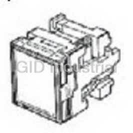
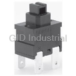
Switch Push Button Rectangular Button Quick Connect/Solder Panel Mount
A3PJ-5706-24E
Part Number
A3PJ-5706-24E
Price
Request Quote
Manufacturer
OMRON ELECTRONIC COMPONENTS
Lead Time
Request Quote
Category
Switches » Switch Push Button
Specifications
Manufacturer
Omron Electronic Components
Manufacturers Part #
A3PJ-5706-24E
Lead Time
10 Week Lead Time
Industry Aliases
A3PJ-5706-24E
Sub-Category
Push Button Switches
Factory Pack Quantity
1
Datasheet

Extracted Text
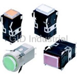
Lighted Pushbutton Switch (Square) A3P CSM_A3P_DS_E_7_2 Large Square-bodied Lighted Pushbutton Switches • Excellent operating sensitivity. • Excellent illumination with even surface brightness. • Three-color models (green, orange, red; chameleon lighting) included in lineup. Refer to Safety Precautions for All Pushbutton Switches/ Indicators and Safety Precautions on page 24. List of Models Model Appearance 52 max. 6.7 A3PJ 25 (Rectangular) 32 52 max. 6.7 A3PA (Square) 25 25 52 max. 6.4 A3PT (Round) 32 dia. Note: The A3PJ is shown in the figure above as an example. ■ Specifications: Refer to page 15. ■ Panel cutout: Refer to page 21. ■ Dimensions: Refer to page 18. ■ Accessories, replacements, and tools: Refer to pages 13 to 15. ■ Precautions for correct use: Refer to page 24. 1 A3P Model Number Structure Model Number Legend ..... The model numbers used to order sets of Units are illustrated below. One set comprises the Pushbutton, Lamp, and Switch. For information on combinations, refer to Ordering Information on pages 3 to 7. (5) (6) 24E R ............... Single screen (1) (2) (3) (4) Upper Lower A 3 P J - 90 B 1 1 - 24E RW ................... Horizontal 2-split screen R (Red) Upper W (White) Lower (1) Shape of (2) Switch (3) Screen Pattern (4) Case Color (5) Lighting (6) Color of Pushbutton Pushbutton Specifications Method For LED Illumination-only models Sym- Color Standard Load bol Symbol Shape Symbol Screen pattern LED-lighted Models Symbol Color 1Black Symbol Operation Rectan- (A3PJ and A3PA RRed J Single screen gular Light A Momentary 1 Models Only) 2 O orange SPDT gray A Square B Alternate G green Rated Note: A3PT Symbol T Round C Momentary voltage Wwhite models are DPDT 2-split screen Momentary opera- D Alternate 2 available in 05E 5 VDC K Chameleon tion: Self-resetting light gray 12E 12 VDC • The chameleon Microload Alternate opera- only. screen pattern is not 24E 24 VDC tion: Self-holding Chameleon *1 Symbol Operation available with A3PT models. E Momentary LED Lamp- • The chameleon SPDT F Alternate lighted Models screen pattern is only G Note: 1. The chameleon screen pattern available with 12 or (A3PT Only) G Momentary is not available with A3PT models. DPDT 24-VDC models. 2. The chameleon screen pattern H Alternate is only available with 12 or 24-VDC Rated Symbol models. • Standard Load For Incandescent voltage 250 VAC, 3 A Lamp *1. With chameleon models, the whole 05C 5 VDC 30 VDC, 3 A screen lights red, green, or orange. • Microload 12C 12 VDC Symbol Color When not lit, the display is white. 125 VAC, 0.1 A • The available rectangular models are 24C 24 VDC Red, 30 VDC, 0.1 A shown below. Select from among the orange, • A3PJ and A3PA No Minimum applicable load individual products shown on page 10. white, can also be 5 VDC, 1 mA symbol ordered blue, Vertical 2-split 4-split screen separately. Refer • 3PDT models are also green screen models models to page 10 for available. • Includes colored details. Select from among the plate. Refer to page individual products shown on Incandescent Horizontal 3-split Vertical 3-split 11 for details. page 12. screen models screen models Lamp-lighted Models Rated The above diagrams show the Switches Symbol voltage with the " " mark facing down. 06 6 VAC/VDC Colored-illumination models up 14 14 VAC/VDC to the 4-split screen models are available as individual Units. 28 28 VAC/VDC Refer to page 8. “Colored-illumination” models operate in the way shown below: Unlit Lit White Color The built-in LED is colored. Number of LED Lamps Number of Incandescent Lamps Screen pattern A3PJ A3PA A3PT Screen pattern A3PJ A3PA A3PT Single screen 2 Single screen 2 1 2 Models with built-in LED Horizontal 2-split screen --- Horizontal 2-split screen 2 --- 4(Low-pow- Vertical 2-split screen Vertical 2-split screen --- --- er incan- descent Horizontal 3-split screen Horizontal 3-split screen --- --- 4 --- --- lamp) *2 Vertical 3-split screen 4-split screen --- --- 4-split screen Note: Lamp positions for single-screen A3PJ (rectangular model). *2. These split screen models are available only as individual Units. They cannot be ordered as sets. 2 A3P Ordering Information Ordering as a Set ................................. The model numbers used to order sets of Units are given in the following tables. One set comprises the Pushbutton, Lamp, and Switch. (Not all combinations are possible. Ask your OMRON representative for details.) (Single Screen) (Single Screen) Rectangular (1) Models A3PJ Standard Loads Contact type Standard load (250 VAC, 3 A; 30 VDC, 4 A) Pushbutton Operation Momentary operation (Self-resetting) Alternate operation (Self-holding) color symbol Case color Black Light gray Black Light gray Output Lighting 5 VDC A3PJ-90A11-05E(1) A3PJ-90A12-05E(1) A3PJ-90B11-05E(1) A3PJ-90B12-05E(1) R O 12 VDC A3PJ-90A11-12E(1) A3PJ-90A12-12E(1) A3PJ-90B11-12E(1) A3PJ-90B12-12E(1) LED G 24 VDC A3PJ-90A11-24E(1) A3PJ-90A12-24E(1) A3PJ-90B11-24E(1) A3PJ-90B12-24E(1) W 12 VDC A3PJ-90AG1-12EK --- A3PJ-90BG1-12EK A3PJ-90BG2-12EK SPDT Chameleon *1 24 VDC A3PJ-90AG1-24EK A3PJ-90AG2-24EK A3PJ-90BG1-24EK A3PJ-90BG2-24EK 6 VDC/VAC A3PJ-90A11-06 A3PJ-90A12-06 A3PJ-90B11-06 A3PJ-90B12-06 Incandescent 14 VDC/VAC A3PJ-90A11-14 A3PJ-90A12-14 A3PJ-90B11-14 A3PJ-90B12-14 *2 lamp 28 VDC/VAC A3PJ-90A11-28 A3PJ-90A12-28 A3PJ-90B11-28 A3PJ-90B12-28 5 VDC A3PJ-90C11-05E(1) A3PJ-90C12-05E(1) A3PJ-90D11-05E(1) A3PJ-90D12-05E(1) R O 12 VDC A3PJ-90C11-12E(1) A3PJ-90C12-12E(1) A3PJ-90D11-12E(1) A3PJ-90D12-12E(1) LED G 24 VDC A3PJ-90C11-24E(1) A3PJ-90C12-24E(1) A3PJ-90D11-24E(1) A3PJ-90D12-24E(1) W 12 VDC A3PJ-90CG1-12EK A3PJ-90CG2-12EK A3PJ-90DG1-12EK --- DPDT Chameleon *1 24 VDC A3PJ-90CG1-24EK A3PJ-90CG2-24EK A3PJ-90DG1-24EK A3PJ-90DG2-24EK 6 VDC/VAC A3PJ-90C11-06 A3PJ-90C12-06 A3PJ-90D11-06 A3PJ-90D12-06 Incandescent 14 VDC/VAC A3PJ-90C11-14 A3PJ-90C12-14 A3PJ-90D11-14 A3PJ-90D12-14 *2 lamp 28 VDC/VAC A3PJ-90C11-28 A3PJ-90C12-28 A3PJ-90D11-28 A3PJ-90D12-28 Note: Enter the desired color symbol for the Pushbutton in (1). (R) = Red, (O) = Orange, (G) = Green, (W) = White. Example: Red A3PJ-90A11-24E R *1. You can change the screen colors of chameleon models between red, green, and orange, by changing the terminal wiring. Refer to page 20 for details. *2. Incandescent lamps are supplied with colored plates (white, red, green, blue, and orange) and legend plates (milk-white and transparent). Use the appropriate combination. Microloads Contact type Microload (125 VAC, 0.1 A; 30 VDC, 0.1 A) Operation Momentary operation (Self-resetting) Pushbutton color symbol Case color Black Light gray Output Lighting 5 VDC A3PJ-90E11-05E(1) A3PJ-90E12-05E(1) R O 12 VDC A3PJ-90E11-12E(1) A3PJ-90E12-12E(1) LED G 24 VDC A3PJ-90E11-24E(1) A3PJ-90E12-24E(1) W 12 VDC A3PJ-90EG1-12EK --- SPDT Chameleon *1 24 VDC A3PJ-90EG1-24EK A3PJ-90EG2-24EK 6 VDC/VAC A3PJ-90E11-06 A3PJ-90E12-06 Incandescent 14 VDC/VAC A3PJ-90E11-14 --- *2 lamp 28 VDC/VAC A3PJ-90E11-28 A3PJ-90E12-28 5 VDC A3PJ-90G11-05E(1) --- R O 12 VDC A3PJ-90G11-12E(1) A3PJ-90G12-12E(1) LED G 24 VDC A3PJ-90G11-24E(1) A3PJ-90G12-24E(1) W 12 VDC A3PJ-90GG1-12EK DPDT Chameleon --- *1 24 VDC A3PJ-90GG1-24EK 6 VDC/VAC A3PJ-90G11-06 A3PJ-90G12-06 Incandescent 14 VDC/VAC A3PJ-90G11-14 A3PJ-90G12-14 *2 lamp 28 VDC/VAC A3PJ-90G11-28 A3PJ-90G12-28 Note: Enter the desired color symbol for the Pushbutton in (1). (R) = Red, (O) = Orange, (G) = Green, (W) = White. Example: Red A3PJ-90E11-24E R *1. You can change the screen colors of chameleon models between red, green, and orange, by changing the terminal wiring. Refer to page 20 for details. *2. Incandescent lamps are supplied with colored plates (white, red, green, blue, and orange) and legend plates (milk-white and transparent). Use the appropriate combination. Individual models: Refer to pages 9 to 12. ■ Specifications: Refer to page 15. ■ Dimensions: Refer to page 18. (The Pushbutton, Lamp, and Switch can be ordered separately.) ■ Accessories: Refer to pages 13 to 15. 3 A3P Ordering Information Ordering as a Set ..................................The model numbers used to order sets of Units are given in the following tables. One set comprises the Pushbutton, Lamp, and Switch. (Not all combinations are possible. Ask your OMRON representative for details.) (1) (Horizontal 2-split Screen) (Horizontal 2-split Screen) Rectangular (2) Models A3PJ Standard Loads Contact type Standard load (250 VAC, 3 A; 30 VDC, 4 A) Operation Momentary operation (Self-resetting) Alternate operation (Self-holding) Pushbutton color symbol Case color Black Light gray Black Light gray Output Lighting LED 5 VDC A3PJ-90A21-24E(1)(2) A3PJ-90A22-24E(1)(2) A3PJ-90B21-24E(1)(2) A3PJ-90B22-24E(1)(2) R O G W 6 VDC/VAC A3PJ-90A21-06 A3PJ-90A22-06 A3PJ-90B21-06 A3PJ-90B22-06 SPDT Incandescent 14 VDC/VAC A3PJ-90A21-14 A3PJ-90A22-14 A3PJ-90B21-14 A3PJ-90B22-14 * lamp 28 VDC/VAC A3PJ-90A21-28 A3PJ-90A22-28 A3PJ-90B21-28 A3PJ-90B22-28 LED 24 VDC A3PJ-90C21-24E(1)(2) A3PJ-90C22-24E(1)(2) A3PJ-90D21-24E(1)(2) A3PJ-90D22-24E(1)(2) R O G W 6 VDC/VAC A3PJ-90C21-06 A3PJ-90C22-06 A3PJ-90D21-06 A3PJ-90D22-06 DPDT Incandescent 14 VDC/VAC A3PJ-90C21-14 A3PJ-90C22-14 A3PJ-90D21-14 A3PJ-90D22-14 * lamp 28 VDC/VAC A3PJ-90C21-28 A3PJ-90C22-28 A3PJ-90D21-28 A3PJ-90D22-28 Note: Enter the desired color symbols for the Pushbutton in (1) and (2). (R) = Red, (O) = Orange, (G) = Green, (W) = White. Example: Red Upper A3PJ-90D21-24E R W WhiteLower Red White * Incandescent lamps are supplied with colored plates (white, red, green, blue, and orange) and legend plates (milky white and transparent). Use the appropriate combination. (1) (Horizontal 2-split Screen) (Horizontal 2-split Screen) Rectangular (2) Models A3PJ Microloads Contact type Microload (125 VAC, 0.1 A; 30 VDC, 0.1 A) Operation Momentary operation (Self-resetting) Pushbutton color symbol Case color Black Light gray Output Lighting LED 5 VDC A3PJ-90E21-24E(1)(2) A3PJ-90E22-24E(1)(2) R O G W 6 VDC/VAC A3PJ-90E21-06 A3PJ-90E22-06 SPDT Incandescent 14 VDC/VAC A3PJ-90E21-14 A3PJ-90E22-14 * lamp 28 VDC/VAC A3PJ-90E21-28 A3PJ-90E22-28 LED 5 VDC A3PJ-90G21-24E(1)(2) A3PJ-90G22-24E(1)(2) R O G W 6 VDC/VAC A3PJ-90G21-06 A3PJ-90G22-06 DPDT Incandescent 14 VDC/VAC A3PJ-90G21-14 A3PJ-90G22-14 * lamp 28 VDC/VAC A3PJ-90G21-28 A3PJ-90G22-28 Note: Enter the desired color symbols for the Pushbutton in (1) and (2). (R) = Red, (O) = Orange, (G) = Green, (W) = White. Example: Red Upper A3PJ-90D21-24E R W WhiteLower Red White * Incandescent lamps are supplied with colored plates (white, red, green, blue, and orange) and legend plates (milky-white and transparent). Use the appropriate combination. Individual models: Refer to pages 9 to 12. ■ Specifications: Refer to page 15. ■ Dimensions: Refer to page 18. (The Pushbutton, Lamp, and Switch can be ordered separately.) ■ Accessories: Refer to pages 13 to 15. 4 A3P Ordering Information Ordering as a Set ................................. The model numbers used to order sets of Units are given in the following tables. One set comprises the Pushbutton, Lamp, and Switch. (Not all combinations are possible. Ask your OMRON representative for details.) (Single Screen) (Single Screen) Square (1) Models A3PA Standard Loads Contact type Standard load (250 VAC, 3 A; 30 VDC, 4 A) Operation Momentary operation (Self-resetting) Alternate operation (Self-holding) Pushbutton color symbol Case color Black Light gray Black Light gray Output Lighting 5 VDC A3PA-90A11-05E(1) A3PA-90A12-05E(1) A3PA-90B11-05E(1) A3PA-90B12-05E(1) R O 12 VDC A3PA-90A11-12E(1) A3PA-90A12-12E(1) A3PA-90B11-12E(1) A3PA-90B12-12E(1) LED G 24 VDC A3PA-90A11-24E(1) A3PA-90A12-24E(1) A3PA-90B11-24E(1) A3PA-90B12-24E(1) W 12 VDC A3PA-90AG1-12EK A3PA-90AG2-12EK A3PA-90BG1-12EK A3PA-90BG2-12EK SPDT Chameleon *1 24 VDC A3PA-90AG1-24EK A3PA-90AG2-24EK A3PA-90BG1-24EK A3PA-90BG2-24EK 6 VDC/VAC A3PA-90A11-06 A3PA-90A12-06 A3PA-90B11-06 A3PA-90B12-06 Incandescent 14 VDC/VAC A3PA-90A11-14 A3PA-90A12-14 A3PA-90B11-14 A3PA-90B12-14 *2 lamp 28 VDC/VAC A3PA-90A11-28 A3PA-90A12-28 A3PA-90B11-28 A3PA-90B12-28 5 VDC A3PA-90C11-05E(1) A3PA-90C12-05E(1) A3PA-90D11-05E(1) A3PA-90D12-05E(1) R O 12 VDC A3PA-90C11-12E(1) A3PA-90C12-12E(1) A3PA-90D11-12E(1) A3PA-90D12-12E(1) LED G 24 VDC A3PA-90C11-24E(1) A3PA-90C12-24E(1) A3PA-90D11-24E(1) A3PA-90D12-24E(1) W 12 VDC A3PA-90CG1-12EK A3PA-90CG2-12EK A3PA-90DG1-12EK A3PA-90DG2-12EK DPDT Chameleon *1 24 VDC A3PA-90CG1-24EK A3PA-90CG2-24EK A3PA-90DG1-24EK A3PA-90DG2-24EK 6 VDC/VAC A3PA-90C11-06 A3PA-90C12-06 A3PA-90D11-06 A3PA-90D12-06 Incandescent 14 VDC/VAC A3PA-90C11-14 A3PA-90C12-14 A3PA-90D11-14 A3PA-90D12-14 *2 lamp 28 VDC/VAC A3PA-90C11-28 A3PA-90C12-28 A3PA-90D11-28 A3PA-90D12-28 Note: Enter the desired color symbol for the Pushbutton in (1). (R) = Red, (O) = Orange, (G) = Green, (W) = White. Example: Red A3PA-90A11-24E R *1. You can change the screen colors of chameleon models between red, green, and orange, by changing the terminal wiring. Refer to page 20 for details. *2. Incandescent lamps are supplied with colored plates (white, red, green, blue, and orange) and legend plates (milk-white and transparent). Use the appropriate combination. Microloads Contact type Microload (125 VAC, 0.1 A; 30 VDC, 0.1 A) Operation Momentary operation (Self-resetting) Pushbutton color symbol Case color Black Light gray Output Lighting 5 VDC A3PA-90E11-05E(1) A3PA-90E12-05E(1) R O 12 VDC A3PA-90E11-12E(1) A3PA-90E12-12E(1) LED G 24 VDC A3PA-90E11-24E(1) A3PA-90E12-24E(1) W 12 VDC A3PA-90EG1-12EK --- SPDT Chameleon *1 24 VDC A3PA-90EG1-24EK A3PA-90EG2-24EK 6 VDC/VAC A3PA-90E11-06 A3PA-90E12-06 Incandescent 14 VDC/VAC --- A3PA-90E12-14 *2 lamp 28 VDC/VAC A3PA-90E11-28 A3PA-90E12-28 5 VDC --- --- R O 12 VDC A3PA-90G11-12E(1) A3PA-90G12-12E(1) LED G 24 VDC A3PA-90G11-24E(1) A3PA-90G12-24E(1) W 12 VDC A3PA-90GG1-12EK DPDT Chameleon --- *1 24 VDC A3PA-90GG1-24EK 6 VDC/VAC A3PA-90G11-06 A3PA-90G12-06 Incandescent 14 VDC/VAC --- --- *2 lamp 28 VDC/VAC A3PA-90G11-28 A3PA-90G12-28 Note: Enter the desired color symbol for the Pushbutton in (1). (R) = Red, (O) = Orange, (G) = Green, (W) = White. Example: Red A3PA-90E11-24E R *1. You can change the screen colors of chameleon models between red, green, and orange, by changing the terminal wiring. Refer to page 20 for details. *2. Incandescent lamps are supplied with colored plates (white, red, green, blue, and orange) and legend plates (milk-white and transparent). Use the appropriate combination. Individual models: Refer to pages 9 to 12. ■ Specifications: Refer to page 15. ■ Dimensions: Refer to page 18. (The Pushbutton, Lamp, and Switch can be ordered separately.) ■ Accessories: Refer to pages 13 to 15. 5 A3P Ordering Information Ordering as a Set ..................................The model numbers used to order sets of Units are given in the following tables. One set comprises the Pushbutton, Lamp, and Switch. (Not all combinations are possible. Ask your OMRON representative for details.) (1) (Horizontal 2-split Screen) (Horizontal 2-split Screen) Square (2) A3PA Models Standard Loads Contact type Standard load (250 VAC, 3 A; 30 VDC, 4 A) Operation Momentary operation (Self-resetting) Alternate operation (Self-holding) Pushbutton color symbol Case color Black Light gray Black Light gray Output Lighting LED 24 VDC A3PA-90A21-24E(1)(2) A3PA-90A22-24E(1)(2) A3PA-90B21-24E(1)(2) A3PA-90B22-24E(1)(2) R O G W 6 VDC/VAC A3PA-90A21-06 A3PA-90A22-06 A3PA-90B21-06 A3PA-90B22-06 SPDT Incandescent lamp 14 VDC/VAC A3PA-90A21-14 A3PA-90A22-14 A3PA-90B21-14 A3PA-90B22-14 * 28 VDC/VAC A3PA-90A21-28 A3PA-90A22-28 A3PA-90B21-28 A3PA-90B22-28 LED 24 VDC A3PA-90C21-24E(1)(2) A3PA-90C22-24E(1)(2) A3PA-90D21-24E(1)(2) A3PA-90D22-24E(1)(2) R O G W 6 VDC/VAC A3PA-90C21-06 A3PA-90C22-06 A3PA-90D21-06 A3PA-90D22-06 DPDT Incandescent lamp 14 VDC/VAC A3PA-90C21-14 A3PA-90C22-14 A3PA-90D21-14 A3PA-90D22-14 * 28 VDC/VAC A3PA-90C21-28 A3PA-90C22-28 A3PA-90D21-28 A3PA-90D22-28 Note: Enter the desired color symbols for the Pushbutton in (1) and (2). (R) = Red, (O) = Orange, (G) = Green, (W) = White. Example: Red Upper A3PA-90D21-24E R W WhiteLower Red White * Incandescent lamps are supplied with colored plates (white, red, green, blue, and orange) and legend plates (milk-white and transparent). Use the appropriate combination. (1) (Horizontal 2-split Screen) (Horizontal 2-split Screen) Square (2) Models A3PA Microloads Contact type Microload (125 VAC, 0.1 A; 30 VDC, 0.1 A) Operation Momentary operation (Self-resetting) Pushbutton color symbol Case color Black Light gray Output Lighting LED 24 VDC A3PA-90E21-24E(1)(2) A3PA-90E22-24E(1)(2) R O G W 6 VDC/VAC A3PA-90E21-06 A3PA-90E22-06 SPDT Incandescent lamp 14 VDC/VAC A3PA-90E21-14 A3PA-90E22-14 * 28 VDC/VAC A3PA-90E21-28 A3PA-90E22-28 LED 24 VDC A3PA-90G21-24E(1)(2) A3PA-90G22-24E(1)(2) R O G W 6 VDC/VAC A3PA-90G21-06 A3PA-90G22-06 DPDT Incandescent lamp 14 VDC/VAC A3PA-90G21-14 A3PA-90G22-14 * 28 VDC/VAC A3PA-90G21-28 A3PA-90G22-28 Note: Enter the desired color symbols for the Pushbutton in (1) and (2). (R) = Red, (O) = Orange, (G) = Green, (W) = White. Example: Red Upper A3PA-90D21-24E R W WhiteLower Red White * Incandescent lamps are supplied with colored plates (white, red, green, blue, and orange) and legend plates (milk-white and transparent). Use the appropriate combination. Individual models: Refer to pages 9 to 12. ■ Specifications: Refer to page 15. ■ Dimensions: Refer to page 18. (The Pushbutton, Lamp, and Switch can be ordered separately.) ■ Accessories: Refer to pages 13 to 15. 6 A3P Ordering Information Ordering as a Set ................................. The model numbers used to order sets of Units are given in the following tables. One set comprises the Pushbutton, Lamp, and Switch. (Single Screen) (Single Screen) Round (1) A3PT Standard Loads Contact type Standard load (250 VAC, 3 A; 30 VDC, 4 A) Momentary operation Alternate operation Operation Pushbutton (Self-resetting) (Self-holding) color symbol Case color Light gray Light gray Output Lighting LED 24 VDC A3PT-90A12-24C(1) A3PT-90B12-24C(1) R O G W 6 VDC/VAC A3PT-90A12-06 A3PT-90B12-06 SPDT Incandescent lamp 14 VDC/VAC A3PT-90A12-14 --- * 28 VDC/VAC A3PT-90A12-28 A3PT-90B12-28 LED 24 VDC A3PT-90C12-24C(1) A3PT-90D12-24C(1) R O G W 6 VDC/VAC A3PT-90C12-06 A3PT-90D12-06 DPDT Incandescent lamp 14 VDC/VAC A3PT-90C12-14 A3PT-90D12-14 * 28 VDC/VAC A3PT-90C12-28 A3PT-90D12-28 Note: Enter the desired color symbols for the Pushbutton in (1) and (2). (R) = Red, (O) = Orange, (G) = Green, (W) = White. Example: Red A3PT-90A12-24C R * Incandescent lamps are supplied with a colored plates (white, red, green, blue, and orange). Use the appropriate combination. Models A3PT (round models), however, are not supplied with legend plates. (Single Screen) (Single Screen) Round (1) A3PT Microloads Microload Contact type (125 VAC, 0.1 A; 30 VDC, 0.1 A) Momentary operation Pushbutton Operation (Self-resetting) color symbol Case color Light gray Output Lighting LED 24 VDC A3PT-90E12-24C(1) R O G W SPDT Incandescent lamp 28 VDC/VAC A3PT-90E12-28 * LED 24 VDC A3PT-90G12-24C(1) G W DPDT Incandescent lamp 28 VDC/VAC A3PT-90G12-28 * Note: Enter the desired color symbols for the Pushbutton in (1). (R) = Red, (O) = Orange, (G) = Green, (W) = White. Example: Red A3PT-90E12-24C R * Incandescent lamps are supplied with a colored plates (white, red, green, blue, and orange). Use the appropriate combination. Models A3PT (round models), however, are not supplied with legend plates. Individual models: Refer to pages 9 to 12. ■ Specifications: Refer to page 15. ■ Dimensions: Refer to page 18. (The Pushbutton, Lamp, and Switch can be ordered separately.) ■ Accessories: Refer to pages 13 to 15. 7 A3P Ordering Information Illumination-only and Colored-illumination LED Models “Illumination only” describes LED models for which the screen color is the same whether the LED is lit or not. The screen simply becomes brighter when the LED lights. Example: Red LED Not lit Cap (transparent) Red Lit Legend plate (transparent) Pushbutton Red (Display) Colored plate (red) Lamp holder LED lamp (red) - - - Lamp “Colored illumination” describes LED models for which the screen color is white when the LED is not lit and changes to the color of the LED lamp when the LED is lit. Example: Red LED Not lit White Cap (transparent) Lit Legend plate (transparent) Red Pushbutton (Display) Colored plate (white) Lamp holder LED lamp (red) - - - Lamp Ordering: With colored-illumination models, order the Pushbutton, Lamp, and Switch as shown in the following table. Pushbutton Lamp Switch Select the LED lamp-lighted model required Select the LED lamps to suit your desired col- from the selection on page 10. Each assembly oration from the selection on page 12. Number includes the number of white colored plates re- of necessary LED lamps (standard) quired to enable colored illumination for the A3PJ (rectangular): 4 Select from the Switches on page 12. corresponding screen-split configuration. For A3PA (square): 2 example, 4-split screen models include 4 white A3PT (round): 2 colored plates. 8 A3P Ordering Information Ordering Individually ............... Pushbuttons, Lamps, and Switches can be ordered separately. Combinations that are not available as sets can be created using individual Units. Also, store the parts as spares for maintenance and repairs. LED-lighted/Chameleon Models LED Lamp-lighted Models Incandescent Lamp-lighted Models (LED is built into the Pushbutton.) (LED lamp and Pushbutton are separate.) (Incandescent lamp and Pushbutton are separate.) Pushbutton Pushbutton Pushbutton Round (A3PT) models not a Round (A3PT) models not av vailab ailable le.. · · F For Pushb or Pushbutton Switch utton Switch · For Pushbutton Switch · For Pushbutton Switch A3P A3P@@-5 -5@@@ @@@- -@@ @@E E A3P@-502@ A3P@-501@ Lamp (LED Lamp)*1 Lamp (Incandescent Lamp)*2 · Standard lamp SLL-@@ · Low-power lamp SLL-@@H SLL-@@E@ Switch * Switch * Switch * Round (A3PT) models not available. · For Pushbutton Switch · For Pushbutton Switch · For Pushbutton Switch A3P@-7@@@-@ A3P@-7@@@-@ A3P@-7@@@-@ * The Switch is compatible with LED-lighted models, LED lamp-lighted models, and incandescent lamp-lighted models. *1. Number of necessary LED lamps. *2. Number of necessary incandescent lamps. Screen pattern A3PJ A3PA A3PT Screen pattern A3PJ A3PA A3PT Single screen 22 Single screen 2 1 2 Horizontal 2-split screen 2 --- Horizontal 2-split screen 2 --- 4 Vertical 2-split screen Vertical 2-split screen 4 (low-power Vertical 3-split screen Vertical 3-split screen incandes- Horizontal 3-split screen Horizontal 3-split screen cent lamp) 4-split screen 4-split screen Ordering set combinations: Refer to page 3 to 7. ■ Specifications: Refer to page 15. ■ Dimensions: Refer to page 18. ■ Accessories: Refer to pages 13 to 15. 9 A3P Ordering Information Ordering Individually................Pushbuttons, Lamps, and Switches can be ordered separately. Combinations that are not available as sets can be created using individual Units. Also, store the parts as spares for maintenance and repairs. Pushbutton LED-lighted Models (LED is built-in.) Split-screen color Selection precau- Appearance White (W) Red (R) Green (G) Orange (O) (color symbol) tions A3PJ-5701 A3PJ-5702 A3PJ-5703 A3PJ-5706 Single screen -@@E -@@E -@@E -@@E • Enter the voltage to Rectangular A3PJ-5711 A3PJ-5712 A3PJ-5713 A3PJ-5716 be used in the@@at White models -@@E -@@E -@@E -@@E the end of the mod- A3PJ-5721 A3PJ-5722 A3PJ-5723 A3PJ-5726 el number. Red -@@E -@@E -@@E -@@E Horizontal Examples of voltag- 2-split screen A3PJ-5731 A3PJ-5732 A3PJ-5733 A3PJ-5736 Green es used: -@@E -@@E -@@E -@@E 5V=@ 0 @ 5 E A3PJ-5741 A3PJ-5742 A3PJ-5743 A3PJ-5746 Orange 12V=@ 1 @ 2 E -@@E -@@E -@@E -@@E 24V=@ 2 @ 4 E A3PA-5701 A3PA-5702 A3PA-5703 A3PA-5706 Horizontal 2-split Single screen -@@E -@@E -@@E -@@E screen models sup- A3PA-5711 A3PA-5712 A3PA-5713 A3PA-5716 port only 24V. White Square models -@@E -@@E -@@E -@@EFor the color of the shaded part, select A3PA-5721 A3PA-5722 A3PA-5723 A3PA-5726 Red -@@E -@@E -@@E -@@E the model accord- Horizontal ing to the colors 2-split screen A3PA-5731 A3PA-5732 A3PA-5733 A3PA-5736 Green given at the top of -@@E -@@E -@@E -@@E the table. A3PA-5741 A3PA-5742 A3PA-5743 A3PA-5746 Orange -@@E -@@E -@@E -@@E Note: 1. A cap, legend plate (transparent), colored plate, white plunger case, and LED (with a current-limiting resistor) are built into the standard lighting unit. 2. Split-screen coloring configurations are given with the OMRON mark on the Switch facing down. 3. The LED is built-in and cannot be replaced individually. LED Lamp-lighted Models (LED is not built-in.) Rectangular models Square models Round models Appearance Selection precautions Screen pattern Screen Model Screen Model Screen Model Parts included: Colored plates (white, red, green, and or- Single screen A3PJ-5021 A3PA-5021 A3PT-5021 ange), a legend plate (transparent), and a light baffle (split-screen models only) are in- cluded. Use the appropriate combination for the LED coloring required. Horizontal A3PJ-5022 A3PA-5022 ---The number of white co lored plates required 2- split screen to enable colored illumination for the corre- sponding screen-split configuration is includ- ed. (For example, 4-split screen models Vertical 2-split include 4 white colored plates). A3PJ-5023 --- --- screen The number of colored plates included for each model are shown in the following table. Screen pattern White Red Green Orange Horizontal 3-split A3PJ-5024 --- --- Single screen 1111 screen Horizontal 2- split screens 2111 Vertical 2-split Vertical 3-split A3PJ-5025 --- --- screens screen Horizontal 3- split screens 3222 Vertical 3-split screens * 4-split screen A3PJ-5026 --- --- 4-split screen 4111 * The following types of colored plates are included with Horizontal and Vertical 3-splitScreen Switches. White: One colored plate for a 2-split screen and two colored plates for a 4-split screen. Red, green, or orange: One colored plate for a 2-split screen and one colored plates for a 4-split screen. Ordering set combinations: Refer to page 3 to 7. ■ Specifications: Refer to page 15. ■ Dimensions: Refer to page 18. ■ Accessories: Refer to pages 13 to 15. 10 A3P Ordering Information Ordering Individually ............... Pushbuttons, Lamps, and Switches can be ordered separately. Combinations that are not available as sets can be created using individual Units. Also, store the parts as spares for maintenance and repairs. Pushbutton Incandescent Lamp-lighted Models (Incandescent lamp is not built-in.) Rectangular models Square models Round models Appearance Selection precautions Screen pattern Screen Model Screen Model Screen Model Parts included: Colored plates (white, red, green, orange, and Single screen A3PJ-5011 A3PA-5011 A3PT-5011 * blue), legend plates (transparent and milk white), and a light baffle (split-screen models only) are supplied. Horizontal 2- A3PJ-5012 A3PA-5012 --- * A3PT (round) models do not contain a legend plate. split screen The number of colored plates included is shown in the following table. Vertical 2-split A3PJ-5013 --- --- screen Screen pattern White Red Green Orange Blue Single screen 1 1111 Horizontal 3-split Horizontal 2- A3PJ-5014 --- --- screen split screens 1 1111 Vertical 2-split screens Vertical 3-split A3PJ-5015 --- --- screen Horizontal 3- split screens 2 2222 Vertical 3-split screens * 4-split screen A3PJ-5016 --- --- 2 2222 4-split screen * The following types of colored plates are included with Horizontal and Vertical 3-splitScreen Switches. All colors: One colored plate for a 2-split screen and one colored plate for a 4-split screen. Chameleon Models (with Built-in LED) Chameleon pushbutton Appearance Rated voltage switch Rectangular 12 VDC A3PJ-5800-12E 24 VDC A3PJ-5800-24E Square 12 VDC A3PA-5800-12E 24 VDC A3PA-5800-24E Note: 1. With chameleon models the whole screen lights red, green, or orange (i.e., red and green simultaneously). 2. A cap, legend plate (transparent), white colored plate, and LED (with a current-limiting resistor) are built into the Pushbutton. Ordering set combinations: Refer to page 3 to 7. ■ Specifications: Refer to page 15. ■ Dimensions: Refer to page 18. ■ Accessories: Refer to pages 13 to 15. 11 A3P Ordering Information Ordering Individually ..........................Pushbuttons, Lamps, and Switches can be ordered separately. Combinations that are not available as sets can be created using individual Units. Also, store the parts as spares for maintenance and repairs. Pushbutton (For information on mounting, refer to page 25.) LED Lamp Voltage 5 VDC 12 VDC 24 VDC Applicable cap (color) Selection precautions (colored plate) Color Model (DC only) Model (DC only) Model (DC only) Red SLL-05ER SLL-12ER SLL-24ER Red In the standard setup, 4 LED lamps are used Yellow SLL-05EY SLL-12EY SLL-24EY Orange with A3PJ models and 2 LED lamps are Green SLL-05EG SLL-12EG SLL-24EG Green used with A3PA and A3PT models. White SLL-05EW SLL-12EW SLL-24EW White Incandescent Lamp Lamp type Standard lamp Low-power lamp Selection precautions Voltage In the standard setup for A3PJ models, 2 lamps are used with sin- 5 VAC/VDC SLL-06 SLL-06H gle screen models, and 4 lamps are used with split-screen models. If 3 or 4 lamps are lit continuously, use low-power lamps. 12 VAC/VDC SLL-14 SLL-14H In the standard setup for A3PA models, 1 lamp is used with single screen models, and 2 lamps are used with split-screen models. 24 VAC/VDC SLL-28 SLL-28H In the standard setup for A3PT models, 2 lamps are used. Switch (common to both incandescent lamp-lighted models and LED models) Rectangular models Square models Round models Appearance Selection precautions Switch Contact Number of Model Model Model type outputs Operation The end digit denotes the Momentary operation A3PJ-7010-1 A3PA-7010-1 A3PT-7010-2 color of the flange: -1 1 denotes a black flange, Alternate operation A3PJ-7020-1 A3PA-7020-1 A3PT-7020-2 and -2 denotes a light gray flange. Round Momentary operation A3PJ-7030-1 A3PA-7030-1 A3PT-7030-2 Silver alloy switches are available 2 contact only in light gray, and not Alternate operation A3PJ-7040-1 A3PA-7040-1 A3PT-7040-2 in black. Use the Switch in combi- Momentary operation A3PJ-7150-1 --- --- nation with the same 3 shape Lamp (rectangu- --- --- Alternate operation A3PJ-7160-1 lar, square or round). Example: For rectangular Momentary operation A3PJ-7050-1 A3PA-7050-1 A3PT-7050-2 Lamp A3PJ-5011, select 1 Switch A3PJ-7@@0-@. Alternate operation A3PJ-7060-1 A3PA-7060-1 A3PT-7060-2 On the Switch itself, how- ever, only 3 digits are Momentary operation A3PJ-7070-1 A3PA-7070-1 A3PT-7070-2 shown, as follows: Gold alloy 2 A3PJ-7@@. contact Alternate operation A3PJ-7080-1 A3PA-7080-1 A3PT-7080-2 Momentary operation is self-resetting, and alter- Momentary operation A3PJ-7170-1 --- --- nate operation is self- 3 holding (i.e., push-on, Alternate operation A3PJ-7180-1 --- --- push-off). Ordering set combinations: Refer to page 3 to 7. ■ Specifications: Refer to page 15. ■ Dimensions: Refer to page 18. ■ Accessories: Refer to pages 13 to 15. 12 Microload Standard load A3P Ordering Information Accessories, Replacements, and Tools Accessories Name Appearance Classification Rectangular Square Application precautions • The Socket cannot be used with Wire-wrap terminal A3PJ-4101 A3PA-4101 when mounting multiple Switch- es or with 3C models. Socket PCB terminal A3PJ-4102 A3PA-4102 You can use the same Sockets for the A3P Ultra Bright Lighted Solder terminal A3PJ-4103 A3PA-4103 Pushbutton Switches. Black A3PJ-4001 A3PA-4001 Short edge barrier (Horizontal mount- ing) (1 pair) Light gray A3PJ-4002 A3PA-4002 The purpose of the barrier is to prevent malfunctioning and to improve design image of the Black A3PJ-4004 Long edge barrier mounting panel. (Vertical mounting) --- Intermediate barrier × 1. (1 pair) Light gray A3PJ-4005 Edge barriers × 1 pair (2 Units). Barrier Mount short barriers horizontally. Mount long barriers vertically. Black A3PJ-4007 A3PA-4007 Short intermediate For details on mounting, refer to barrier (Horizontal page 25. mounting) Light gray A3PJ-4008 A3PA-4008 You can use the same Sockets for the A3P Ultra Bright Lighted Pushbutton Switches. Black A3PJ-4010 Long intermediate barrier (Vertical --- mounting) Light gray A3PJ-4011 Can be used by exchanging with the cap. For horizontal mounting (with Cannot be used with seal cover. A3PJN-5050 A3PAN-5050 OMRON logo facing down) Can be used with barrier. Use horizontal mounting guard for consecutive horizontal Switch guard mounting, and use vertical mounting guard for consecutive vertical mounting. For vertical mounting (with OM- A3PJN-5055 A3PAN-5055 You can use the same Sockets RON logo facing to the right) for the A3P Ultra Bright Lighted Pushbutton Switches. Cannot be used with barrier and/ or switch guard. For details on mounting, refer to page 25. Seal cover --- A3PJ-5060 A3PA-5060 Cap is manufactured from vinyl chloride. You can use the same Sockets for the A3P Ultra Bright Lighted Pushbutton Switches. Use when vertically mounting in- dividual (with barrier) or multiple Switches (in standard mounting style and with barrier). Since a Long mounting short mounting plate is attached --- A3PJ-3002 --- plate to the Switch, replace it with the long one. You can use the same Sockets for the A3P Ultra Bright Lighted Pushbutton Switches. 13 A3P Ordering Information Accessories Name Appearances Classification A3PJ A3PA Application precautions White A3PJ-5101 A3PA-5101 Single screen Red A3PJ-5102 A3PA-5102 Green A3PJ-5103 A3PA-5103 Blue A3PJ-5104 A3PA-5104 Yellow A3PJ-5105 A3PA-5105 Orange A3PJ-5106 A3PA-5106 White A3PJ-5121 A3PA-5121 Horizontal 2- Red A3PJ-5122 A3PA-5122 split screenKeep mounted at all times. Green A3PJ-5123 A3PA-5123 Contact your OMRON representa- Blue A3PJ-5124 A3PA-5124 tive for color changes or other Yellow A3PJ-5125 A3PA-5125 specifications. Colored plate Orange A3PJ-5126 A3PA-5126 For details on mounting, refer to for incandes- page 25. White A3PJ-5131 --- cent lamp Vertical 2-split You cannot use the same Colored Red A3PJ-5132 --- screen Plates for Incandescent Lamps for Green A3PJ-5133 --- the A3P Ultra Bright Lighted Push- Blue A3PJ-5134 --- button Switches. Yellow --- --- Orange A3PJ-5136 --- White A3PJ-5161 --- 4-split screen Red A3PJ-5162 --- Green A3PJ-5163 --- Blue --- --- Yellow A3PJ-5165 --- Orange A3PJ-5166 --- White A3PJ-5301 A3PA-5301 Single screen Red A3PJ-5302 A3PA-5302 Green A3PJ-5303 A3PA-5303 Yellow A3PJ-5305 A3PA-5305 Orange A3PJ-5306 A3PA-5306 White A3PJ-5321 A3PA-5321 Horizontal 2- Keep mounted at all times. split screen Red A3PJ-5322 A3PA-5322 If the colored plate is lost or dam- aged, contact OMRON. Green A3PJ-5323 A3PA-5323 Use in accordance with coloring of Yellow A3PJ-5325 A3PA-5325 the built-in LED. Orange A3PJ-5326 A3PA-5326 Colored plate For details on mounting, refer to for LED White A3PJ-5331 --- Vertical 2-split page 25. screen Red A3PJ-5332 --- You cannot use the same Colored Green A3PJ-5333 --- Plates for Incandescent Lamps for Yellow A3PJ-5335 --- the A3P Ultra Bright Lighted Push- button Switches. Orange A3PJ-5336 --- White A3PJ-5361 --- 4-split screen Red A3PJ-5362 --- Green A3PJ-5363 --- Yellow A3PJ-5365 --- Orange A3PJ-5366 --- Horizontal 2-split screen A3PJ-4302 A3PA-4302 Keep mounted at all times. If the light baffle is lost, contact Vertical 2-split screen A3PJ-4303 --- OMRON. Long axis A3PJ-4304 --- Horizontal 3- Used in LED lamp-lighted models. split screen Short axis A3PJ-4305 --- Cannot be used in LED-lighted Light baffle models. Long axis A3PJ-4306 --- Vertical 3-split You cannot use the same Colored screen Short axis A3PJ-4307 --- Plates for Incandescent Lamps for Long axis A3PJ-4304 --- the A3P Ultra Bright Lighted Push- 4-split screen Short axis A3PJ-4308 --- button Switches. A transparent legend plate is Transparent legend plate A3PJ-5202 A3PA-5202 mounted on the Pushbutton. You cannot use the same Colored Legend plate Plates for Incandescent Lamps for the A3P Ultra Bright Lighted Push- Milk-white legend plate A3PJ-5201 A3PA-5201 button Switches. You can use the same Sockets for Transparent cap A3PJ-5600 A3PA-5600 the A3P Ultra Bright Lighted Push- button Switches. The surface is cr imp-processed, so Cap there is no reflection. Crimp-processed transpar- A3PJ-5600-A A3PA-5600-A You can use the same Sockets for ent cap the A3P Ultra Bright Lighted Push- button Switches. 14 A3P Ordering Information Tools Name Appearance Classification Model Application precautions Use to extract components when replacing the Pushbutton. Extractor --- A3PJ-5080 You can use the same Sockets for the A3P Ultra Bright Lighted Push- button Switches. Specifications Approved Standard Ratings Ratings UL (File No. E41515), CSA (File No. LR45258) Contact Ratings Standard Load: 5 A at 125 VAC Silver Alloy Contacts (for Standard Loads) 3 A at 250 VAC Non-inductive load (A) Inductive load (A) Rated Microload: 0.1 A at 125 VAC voltage Resistive load Lamp load Inductive load Motor load 0.1 A at 30 VDC (V) NC NO NC NO NC NO NC NO Note: Certification has been obtained for the Switch Unit. 125 VAC 5 0.7 3 1.3 For detailed information on individual products that have received 250 VAC 3 0.5 2 0.8 certification, consult your supplier. 8 VDC 5 2 4 3 14 VDC 5 2 4 3 CCC (GB14048.5) 30 VDC 4 2 3 3 Standard Load: 3 A at 250 VAC 125 VDC 0.4 0.05 0.4 0.05 250 VDC 0.2 0.03 0.2 0.03 4 A at 30 VDC Note: 1. The above values are for steady-state currents. Microload: 0.1 A at 125 VAC 2. Inductive load: Power factor = 0.4; time constant = 7 ms. 0.1 A at 30 VDC 3. The lamp load has an inrush current of 10 times the steady-state current. 4. The motor load has an inrush current of 6 times the steady-state current. Standard testing condition (1) Ambient temperature: 20 ± 2°C (2) Ambient humidity: 65 ± 5%RH (3) Operating frequency: 20 times/min. Gold Alloy Contacts (for Microloads) 0.1 A at 30 VDC (resistive load); Rated voltage (V) 0.1 A at 125 VAC (resistive load) Minimum applicable load 1 mA at 5 VDC LED and Incandescent Lamp Ratings Characteristics LED for LED-lighted Models Mechanical 120 operations/minute max. *1 Operating frequency Electrical 30 operations/minute max. Model A3PJ/M2PJ A3PA/M2PA Insulation resistance 100 MΩ min. (at 500 VDC) Rated current Rated current Standard load 40 mΩ max. (initial value) Contact Applied Rated Single 2-split Single 2-split resistance Microload 40 mΩ max. (initial value) voltage voltage screen screen screen screen Between terminals of same polarity 1,000 VAC, 50/60 Hz for 1 minute *2 5 VDC±5% 5 VDC 80 mA --- 80 mA --- Between terminals of different polarity 2,000 VAC, 50/60 Hz for 1 minute 12 VDC±5% 12 VDC 40 mA --- 40 mA --- Between current-carrying metal Dielectric 2,000 VAC, 50/60 Hz for 1 minute part and ground 24 VDC±5% 24 VDC 20 mA 15 mA × 2 20 mA 13 mA × 2 strength Between each terminal and 2,000 VAC, 50/60 Hz for 1 minute non-current-carrying metal part LED for Chameleon Models Between lamp terminals 1,000 VAC, 50/60 Hz for 1 minute *3 Rated current 10 to 55 Hz, 1.5 mm double am- Vibration resistance Malfunction Applied voltage Rated voltage plitude (1 ms max.) Green Red 2 Destruction 500 m/s max. 12 VDC±5% 12 VDC 26 mA 20 mA Shock resistance 2 Malfunction 200 m/s max. (1 ms max.) 24 VDC±5% 24 VDC 13 mA 10 mA Momentary operation models: 1,000,000 operations min. Incandescent Lamp Alternate operation models: Mechanical 200,000 operations min. Life expectancy Item Standard lamp Low-power lamp (One operation consists of set and reset operations.) Applied voltage Rated voltage Rated current Model Rated current Model Electrical 100,000 operations min. 5 VDC 6 V 200 mA SLL-06 100 mA SLL-06H Weight Approx. 30 g 12 VDC 14 V 80 mA SLL-14 40 mA SLL-14H NC Silver contact: 10 A max. Inrush current 24 VDC 28 V 40 mA SLL-28 25 mA SLL-28H NO Silver contact: 10 A max. LED-lighted models: −10°C to 40°C LED Lamp (for LED Lamp-lighted Models) (with no icing or condensation) Ambient operating temperature Incandescent lamp-lighted models: Type Applied voltage Rated voltage Rated current Model −10°C to 50°C (with no icing or condensation) 5 VDC±5% 5 VDC 30 mA SLL-05E@ Ambient operating humidity 35% to 85%RH DC only 12 VDC±5% 12 VDC 15 mA SLL-12E@ Ambient storage temperature −25°C to 65°C 24 VDC±5% 24 VDC 12.5 mA SLL-24E@ Degree of protection IP40 Electric shock protection class Class II PTI (proof tracking index) 175 Pollution degree 3 (IEC947-5-1) *1. With alternate operation models, 60 operations/minute max. One operation cycle consists of set and reset operations. *2. 600 VAC for microloads. *3. With no incandescent lamp or LED lamp mounted. 15 A3P Specifications Operating Characteristics Model A3PJ series A3PA series A3PT series Operating Momentary Alternate Momentary Alternate Momentary Alternate Characteristics operation models operation models operation models operation models operation models operation models Operating force OF max. 5.88 N 6.86 N 5.88 N 6.86 N 3.92 N 4.90 N Releasing force RF min. 0.39 N 0.29 N 0.39 N 0.29 N 0.39 N 0.29 N Total travel TT Approx. 3.5 mm Approx. 3.5 mm Approx. 3.5 mm Approx. 3.5 mm Approx. 3.5 mm Approx. 3.5 mm Pretravel PT max. 3 mm 3 mm 3 mm 3 mm 3 mm 3 mm Lock travel alternate LTA min. --- 0.5 mm --- 0.5 mm --- 0.5 mm Nomenclature Model Structure Lighting LED-lighted models LED lamp-lighted models Incandescent lamp-lighted models method (LED is built-in.) (LED lamp is not built-in.) (Incandescent lamp is not built-in.) Models A3PJ A3PA A3PJ A3PA A3PT A3PJ A3PA A3PT Single Single Single Single Single Single Single Vertical 3-split Single Vertical 3-split screen screen screen screen screen screen screen screen screen screen Horizontal 2-split Horizontal 2-split Horizontal 2-split Horizontal 2-split Horizontal 3-split Horizontal 2-split Horizontal 2-split Horizontal 3-split screen Screen screen screen screen screen screen screen screen patterns Chameleon Chameleon Vertical 2-split Vertical 2-split 4-split screen 4-split screen (3-color) (3-color) screen screen LED-lighted models Incandescent lamp-lighted models LED lamp-lighted models Chameleon models (full screen LED-lighted models illumination in one of three colors) Cap Cap Cap (transparent) (transparent) (transparent) Pushbutton Legend plate * (Split-screen models (transparent) contain a light Legend plate Legend plate baffle.) (transparent) (transparent) ●Pushbutton colors Colored plate · LED-lighted models and Colored Colored plate LED lamp-lighted models plate White, Red, Green, Orange Lamp LED Unit LED Unit holder · Incandescent lamp-lighted model 3-color emitter Built-in LED White, Red, Green, Blue, Orange * Incandescent lamp-lighted A3PT models do not contain a legend plate. ●Switch Specifications Lamp Standard load ●Case Color · 250 VAC, 3 A Select either black or light 30 VDC, 4A Microload gray to suit your panel design. Switch · 125 VAC, 0.1 A (The round A3PT 30 VDC, 0.1 A models are available in Minimum applicable load: 5 VDC, 1 mA light gray only.) 16 A3P Nomenclature A3P Lighting Method Diagram The following diagram shows the Switches with the mark facing down. Single screen Horizontal 2-split LED-lighted • As a set: See page 3. models screen models models • Individually: See page 9. Single screen Horizontal 2-split Vertical 2-split models screen models screen models LED LED • Individually: See page 9. lamp-lighted models (Not available as a set.) models Vertical 3-split Horizontal 3-split 4-split screen screen models screen models A3PJ Single screen (rectangular) Chameleon models • As a set: See page 3. models • Individually: See page 9. (Full screen illumination in one of three colors) Single screen Horizontal 2-split Vertical 2-split models screen models screen models* Incandescent lamplighted models • As a set: See page 3. • Individually: See page 9. Vertical 3-split Horizontal 3-split 4-split screen *Models indicated with an asterisk are only screen models* screen models* models* available individually. Single screen Horizontal 2-split models screen models LED-lighted • As a set: See page 5. • Individually: See page 9. models Single screen Horizontal 2-split LED models screen models • Individually: See page 9. LED lamp-lighted (Not available as a set.) models models A3PA Single screen (square) Chameleon models • As a set: See page 5. models • Individually: See page 9. Single screen Horizontal 2-split models screen models Incandescent lamplighted • As a set: See page 5. models • Individually: See page 9. Single screen LED models LED lamp-lighted • As a set: See page 7. models models • Individually: See page 9. A3PT (round) Single screen models Incandescent lamplighted • As a set: See page 7. models • Individually: See page 9. 17 A3P Dimensions The Dimension shows 2-switch outputs. (Unit: mm) A3PJ (Rectangular) Models A3PA (Square) Models 2.8 22 26.1 29.9±0.2 0.5 OMRON logo #110 quick connect terminal/ solder terminal #110 quick connect terminal/ OMRON logo solder terminal 25±0.1 19.1 × 19.1 25±0.1 22.9±0.2 18.9 22.9±0.2 Separator 43.6 Separator 25±0.1 6.7 43.6 6.7 32±0.1 52 max. 52 max. 52.6 52.6 A3PT (Round) Models #110 quick connect terminal/solder terminal 22.4 28.5 dia. OMRON logo 24.9 dia. 23.8 32 dia. 6.4 43.6 52 max. 52.6 Note: The thickness of tab terminals #110 and solder terminals is 0.5 mm. 18 A3P Dimensions (Unit: mm) Terminal connections LED-lighted Models (The terminal arrangement diagram shows a 1-switch output. Connections to terminals from the lighting block are the same for 2 outputs.) Rated voltage 5 VDC 12 VDC 24 VDC Screen Model pattern Bottom view Top view Bottom view Top view Bottom view Top view Single screen NO1 NO1 NO1 NC1 NC1 NC1 LC+ LC+ LC+ C1 C1 C1 Terminal Lighting block Terminal Lighting block Terminal Lighting block arrangement arrangement arrangement A3PJ Bottom view Top view Bottom view Top view Horizontal 2-split screen NO1 NO1 L2 NC1 NC1 LC+ LC+ C1 C1 Terminal Lighting block Terminal Lighting block arrangement arrangement Bottom view Top view Bottom view Top view Bottom view Top view Single screen NO1 NO1 NO1 LC+ LC+ LC+ NC1 NC1 NC1 C1 C1 C1 Terminal Lighting block Terminal Lighting block Terminal Lighting block arrangement arrangement arrangement A3PA Bottom view Top view Bottom view Top view 2-split screen NO1 NO1 LC+ LC+ NC1 NC1 C1 C1 Terminal Lighting block Terminal Lighting block arrangement arrangement 19 A3P Dimensions (Unit: mm) Incandescent Lamp-lighted/LED Lamp-lighted Models (All are shown with the OMRON logo facing down. The terminal arrangements are the same as for the LED-lighted models.) Model Rectangular A3PJ models Square A3PA models Round A3PT models Output Bottom view Top view Bottom view Top view Bottom view Top view NO1 NO1 NO1 LC+ LC+ NC1 NC1 NC1 SPDT LC+ C1 C1 C1 Terminal Lighting block Terminal Lighting block Terminal Lighting block arrangement arrangement arrangement Bottom view Top view Bottom view Top view Bottom view Top view NO1 NO2 NO1 NO2 NO1 NO2 LC+ LC+ NC1 NC2 NC1 NC2 PPDT NC1 NC2 C1 C2 LC+ C1 C2 C1 C2 Terminal Lighting block Terminal Lighting block Terminal Lighting block arrangement arrangement arrangement Bottom view Top view NO1 NO2 NO3 NC1 NC2 NC3 3PDT --- --- C1 C2 C3 LC+ Terminal Lighting block arrangement LED Chameleon Models (The terminal arrangement diagram shows a 1-switch output. Connections to terminals from the lighting block are the same for 2 outputs.) Rated voltage 24 VDC Model Rectangular L2− NO1 A3PJ model L1− NC1 L4− LC+ C1 L3− Square A3PA NO1 model L1− LC+ NC1 L2− C1 Terminal Arrangement and Coloring Chameleon Models LC+ LC+ LC+ Wiring L1− and L2− L1− L2− shorted Coloring Green Red Orange 20 A3P Dimensions (Unit: mm) Panel Cutout (If using a Switch Guard or Seal Cover, refer to the panel cutout diagrams on page 23.) A3PJ (Rectangular) Models Classification Mounting design Panel cutout Remarks ±0.3 Individual 30.5 ±0.1 25 mounting ±0.3 (Horizontal) 23.5 ±0.1 32 ±0.3 Multiple 32n−1.5 ±0.1 25 n 12 Panel cutout spacing between rows of Units: mounting ±0.3 (Horizontal) 23.5 ±0.5 32n 3 min. Flange mount Mount to long ±0.3 models 23.5 Individual 6 min. ±0.1 32 mounting plate mounting (A3PJ-3002) ±0.3 (Vertical) 30.5 before use. ±0.1 25 Mount to long ±0.3 25n−1.5 Multiple ±0.1 32 12 n mounting plate mounting (A3PJ-3002) ±0.3 30.5 (Vertical) ±0.5 25n before use. Individual ±0.3 36.4 27 mounting (Horizontal) ±0.3 23.5 39 For barrier mount models, refer to Accessories on Multiple ±0.3 32.9n+3.5 page 13. 27 1 2 n mounting Panel cutout spacing between rows of Units: (Horizontal) ±0.3 ±1 23.5 33n+6 (Dotted line indicates the position of each mounting Barrier barrier.) mount Mount to long ±0.3 Individual 29.4 1.3 6 min. models 34 mounting plate mounting (A3PJ-3002) ±0.3 (Horizontal) 30.5 before use. 6 min. ±0.1 32 Mount to long ±0.3 25.9n+3.5 Multiple 34 mounting plate 1 2 n mounting (A3PJ-3002) ±0.3 30.5 (Vertical) ±1 26n+6 before use. Note: 1. n: Number of Units 2. Recommended panel thickness: 1 to 5 mm 3. Mount the panel before mounting the Switch Guard. 4. If the panel is to be finished (e.g., coated), make sure that the panel meets the specified dimensions after the coating. A3PA (Square) Models Classification Mounting design Panel cutout Remarks ±0.3 ±0.1 23.5 Panel cutout spacing between rows of Units: 25 Individual mounting 3 min. Flange ±0.3 ±0.1 22.5 25 mount models 6 min. ±0.1 ±0.3 Multiple 25 23.5 12 n mounting ±0.3 ±0.1 25n−2.5 25n Panel cutout spacing between rows of Units: ±0.3 23.5 Individual 27 (Dotted line indicates the position of each mounting barrier.) mounting Barrier ±0.3 32 27.8 1.3 6 min. mount models 6 min. Multiple ±0.3 271n 2 23.5 mounting ±0.3 26n+2.5 ±1 26n+6.5 Note: 1. n: Number of Units 2. Recommended panel thickness: 1 to 5 mm 3. Mount the panel before mounting the Switch Guard. 4. If the panel is to be finished (e.g., coated), make sure that the panel meets the specified dimensions after the coating. A3PT (Round) Models 6.4 dia. +0.2 11.8R −0 ±0.3 29 dia. Note: 1. Recommended panel thickness: 1 to 5 mm 2. If the panel is to be finished (e.g., coated), make sure that the panel meets the specified dimensions after the coating. 4 min. 21 A3P Dimensions (Unit: mm) Accessory Mounting Dimensions Legend Plate Extractor Rectangular Models Square Models A3PJ-5080 20 A3PJ-5201/-5202 A3PA-5201/-5202 2.5 2.5 25.1 17.2 10 15 5 16.9 17.2 50 0.3 Plate surface 1.2 1.5 ±2 25 1.5 Note: Made from stainless steel. 24 Socket-mounting Dimensions Rectangular Models A3PJ (M2PJ) Square Models A3PA (M2PA) 25.6 25.6 Wire-wrap Terminal Wire-wrap Terminal 18 18 A3PJ-4101 A3PA-4101 24 31.8 1 × 1 Wire-wrap Terminal 1 × 1 Wire-wrap Terminal 22.8 22.8 61.6 ±0.8 18.5 61.6 ±0.8 18.5 PCB Terminal 25.6 25.6 PCB Terminal 18 18 A3PA-4102 A3PJ-4102 1.2 3 1.2 3 24 31.8 0.3 0.3 22.8 22.8 61.6 3.6 61.6 0.5 3.6 0.5 PCB Cutout PCB Cutout (bottom view) (bottom view) 1.5 8.8 5.25 8.4 17.6 8.7 5.2 10.5 10.4 17.4 2.05 8.65 1.25 3.5 Nine, 1.5-dia. holes 7 Eleven, 1.5-dia. holes 6.15 10.2 20.45 7 11.65 25.6 Solder Terminal 25.6 Solder Terminal 18 18 A3PJ-4103 A3PA-4103 Terminal Hole 3 Dimensions 3 Terminal Hole 24 0.8 31.8 Dimensions 3.2 0.8 0.3 0.3 3.2 3 3 0.9R 0.6R 22.8 0.9R 0.6R 22.8 61.6 61.6 8.2 8.2 Note: PCB cutout dimensions show the switch mounted to the socket with the OMRON logo facing down. 22 A3P Dimensions (Unit: mm) Switch and Guard Mounting Dimensions Rectangular Models Square Models A3PJN-5050 (Horizontal Mounting) A3PAN-5050 (Horizontal Mounting) 52.6 52.6 A3PJN-5055 (Vertical Mounting) A3PAN-5055 (Vertical Mounting) 52 max. 52 max. Spring Spring 43.6 Guard 9.6 43.6 9.6 25±0.1 25.4 25±0.1 25.2 25±0.1 Switch Guard 32±0.1 Switch Guard (A3AN-5050) (A3PJN-5050) OMRON logo OMRON logo 19.1 26.2±0.2 Panel Cutouts Individual Mounting Multiple Mounting Panel Cutouts (Horizontal) (Horizontal) Individual Mounting Multiple Mounting (Horizontal) (Horizontal) 22.5±0.3 25n-2.5±0.3 32n-1.5±0.3 30.5±0.3 23.5±0.3 23.5±0.3 23.5±0.3 23.5±0.3 n = Number of mountings n = Number of mountings Note: Multiple vertical mounting is not possible. Note: Multiple vertical mounting is not possible. Seal Cover Mounting Dimensions Cover A (transparent) Cover B (black) Rectangular Models Square Models Cover A (transparent) Cover B (black) A3PJ-5060 A3PA-5060 OMRON logo Seal Cover OMRON logo Seal cover (A3PJ-5060) (A3PA-5060) 32.5 32.5 39.5 9.3 42.9 32.5 8.7 42.9 51.3 max. 51.3 max. 51.9 51.9 Panel Cutouts Multiple Mounting Panel Cutouts Multiple Mounting Individual Mounting (Horizontal) Individual Mounting 9.5 min. (Horizontal) ±0.3 22.5 10.5 min. 30.5±0.3 ±0.3 22.5 ± 30.5 0.3 23.5±0.3 23.5±0.3 23.5±0.3 23.5±0.3 9.5 min. 9.5 min. Note: 1. Recommended panel thickness: 1 to 5 mm 2. Unless otherwise specified, a tolerance of ± 0.4 mm applies to all dimensions. 23 A3P Safety Precautions Refer to Safety Precautions for all Pushbutton Switches/Indicators. Caution Do not apply a voltage higher than the maximum Using Microloads rated operating voltage between the lamp • Using a standard load switch when a microload circuit is opened or terminals, as there is a risk that the incandescent closed may cause contact failure on the contacts. Use the switch lamp or LED will be damaged, and the Pushbutton within the operating range. (Refer to the diagram below.) Even will be ejected. when using microload models within the operating range shown below, if inrush current occurs when the contact is opened or When replacing the incandescent lamp, first turn closed, it may cause the contact surface to become rough, and so OFF the power supply, and then wait 10 minutes decrease life expectancy. Therefore, insert a contact protection before performing replacement, as the lamp is still circuit where necessary. The minimum applicable load is the N- hot immediately after the power is turned OFF, so level reference value. This value indicates the malfunction there is a risk of burns. reference level for the reliability level of 60% (λ 60) (conforming to −6 JIS C5003). The equation, λ 60 = 0.5 x 10 /time indicates that the Precautions for Correct Use estimated malfunction rate is less than 1/2,000,000 with a reliability level of 60%. 1. Always make sure that the power is turned OFF before mounting, removing, or wiring the Switch, or performing maintenance. Electric shock or fire may occur. 0.15 mA 26 mA 100 mA 30 2. After wiring the Switch, make sure that there is a suitable isolation distance. 24 Wiring • Solder quickly and correctly at 350°C max and for 3 s or less. Standard Microload load area Wait for one minute after soldering before exerting any external area force on the solder. Operating Environment 12 Invalid • Do not use in locations that are subject to dust, oil, or metal filings area as these may penetrate the interior of the Switch and cause 5 malfunction. 1 mA 100 mA 160 mA 0 LED (for VDC) 0.1 1 10 100 1,000 • Check the terminal polarity when wiring. Current (mA) • The rated voltage is shown on the plate on the back of the lighting Others unit, so be sure to use within the voltage shown. • An LED current-limiting resistor is built in, so there is no need to • If the panel is to be finished (e.g., coated), make sure that the panel mount an external resistor. meets the specified dimensions after the coating. Incandescent Lamp • Apply 80% of the rated voltage (operating voltage) to the incandescent lamp to improve life expectancy and incandescence. Character Plate (Character Film) • If preparing the character plate separately, use a heat-resistant film with a thickness of 0.1 to 0.3 mm. +0 +0 24.1 17.1 −0.1 −0.3 +0 +0 17.1 17.1 −0.3 −0.3 +0 24.8 dia. −0.3 23.±0.1 dia. +0 5.2 −0.3 24 Voltage (V) A3P Assembly/Disassembly A3PJ/M2PJ (Rectangular Models), A3PA/M2PA (Square Models) Locking/Unlocking Positive Cap Lock Mechanism Mounting and Replacing LED and Incandescent Lamps If using an A3PA (square) model with one incandescent lamp, insert Unlock Lock the lamp in the center hole. Positive cap stopper Mounting Pushbutton • Be sure to mount the Pushbutton with the correct orientation. Align the groove on the Pushbutton, the projections in the Switch, and the Note: Built-in LEDs cannot be replaced. LED contact piece before pushing the Pushbutton into the Switch. • When dismounting the Pushbutton, use the Extractor (A3PJ-5080) LED Rated Voltage Display (LED Models Only) for easy dismounting. The LED rated voltage is shown between the built-in resistors on the back of the lighting unit. Use within a range of ± 5%. OMRON logo Groove A3PJ Rated voltage display A3PA LED contact piece Diagram shows A3PA model. Removing/Mounting Cap Note: Display is on the back. Insert the A3PA from the open side into the theft-prevention stopper. Mounting Switch onto Panel • Individual Mounting • Multiple Barrier Mounting (A3PJ) and Barrier Mounting When mounting a number of Switches in When mounting the Switch, line on the panel, link the Switches with push it into the panel cutout spacing barriers in between, attach from the front of the mounting barriers at both sides of this block mounting panel by holding it of Switches and, pushing in on the with the logo mark mounting barriers at the side, insert the Mounting Colored Plate “OMRON” facing downward. Switches into the panel cutout together. Place the colored plate on the plunger case with the dull side of the colored plate facing downward. With A3PJ split-screen models, be sure that the projections on the upper surface of the colored plate face outward. For the A3PA, make sure that the flat plate is facing upwards. Flat plate Projection OMRON OMRON logo logo A3PA A3PJ Mounting Barriers Mount each part by pushing it in the direction of the arrow shown in the corresponding illustration below. Barrier mounting Mounting Character Plate (Character Frame) and Legend Plate Mount the legend plate for the A3PJ under the layered surfaces and mount the cap, as shown below. Transparent cap Legend plate (Character plate) Colored plate (Light baffle) 25 A3P Mounting Seal Cover After mounting the seal cover onto the flange of the Switch, push the Switch into the panel cutout. Inscribing the Legend Plate • Inscribe the legend plate to a depth of 0.5 mm max. • The legend plate is made from polycarbonate resin. To coat the legend plate, use an alcohol-based coating such as melamine, phthalic acid, or acrylic. Maintenance Lock 1. First, when you insert the transparent lens while pressing the center, the maintenance lock mechanism will be activated, and the Switch will not operate. Lamp replacement and other maintenance can be performed without turning OFF the power supply to devices and equipment. Use an insertion force of 4 kg. 2. Next, when you remove your finger from the Switch, the lock will be released. 3. The Switch will start to operate when the lighting unit is pressed the second time. 26 Terms and Conditions Agreement Read and understand this catalog. Please read and understand this catalog before purchasing the products. Please consult your OMRON representative if you have any questions or comments. Warranties. (a) Exclusive Warranty. Omron’s exclusive warranty is that the Products will be free from defects in materials and workmanship for a period of twelve months from the date of sale by Omron (or such other period expressed in writing by Omron). Omron disclaims all other warranties, express or implied. (b) Limitations. OMRON MAKES NO WARRANTY OR REPRESENTATION, EXPRESS OR IMPLIED, ABOUT NON-INFRINGEMENT, MERCHANTABILITY OR FITNESS FOR A PARTICULAR PURPOSE OF THE PRODUCTS. BUYER ACKNOWLEDGES THAT IT ALONE HAS DETERMINED THAT THE PRODUCTS WILL SUITABLY MEET THE REQUIREMENTS OF THEIR INTENDED USE. Omron further disclaims all warranties and responsibility of any type for claims or expenses based on infringement by the Products or otherwise of any intellectual property right. (c) Buyer Remedy. Omron’s sole obligation hereunder shall be, at Omron’s election, to (i) replace (in the form originally shipped with Buyer responsible for labor charges for removal or replacement thereof) the non-complying Product, (ii) repair the non-complying Product, or (iii) repay or credit Buyer an amount equal to the purchase price of the non-complying Product; provided that in no event shall Omron be responsible for warranty, repair, indemnity or any other claims or expenses regarding the Products unless Omron’s analysis confirms that the Products were properly handled, stored, installed and maintained and not subject to contamination, abuse, misuse or inappropriate modification. Return of any Products by Buyer must be approved in writing by Omron before shipment. Omron Companies shall not be liable for the suitability or unsuitability or the results from the use of Products in combination with any electrical or electronic components, circuits, system assemblies or any other materials or substances or environments. Any advice, recommendations or information given orally or in writing, are not to be construed as an amendment or addition to the above warranty. See http://www.omron.com/global/ or contact your Omron representative for published information. Limitation on Liability; Etc. OMRON COMPANIES SHALL NOT BE LIABLE FOR SPECIAL, INDIRECT, INCIDENTAL, OR CONSEQUENTIAL DAMAGES, LOSS OF PROFITS OR PRODUCTION OR COMMERCIAL LOSS IN ANY WAY CONNECTED WITH THE PRODUCTS, WHETHER SUCH CLAIM IS BASED IN CONTRACT, WARRANTY, NEGLIGENCE OR STRICT LIABILITY. Further, in no event shall liability of Omron Companies exceed the individual price of the Product on which liability is asserted. Suitability of Use. Omron Companies shall not be responsible for conformity with any standards, codes or regulations which apply to the combination of the Product in the Buyer’s application or use of the Product. At Buyer’s request, Omron will provide applicable third party certification documents identifying ratings and limitations of use which apply to the Product. This information by itself is not sufficient for a complete determination of the suitability of the Product in combination with the end product, machine, system, or other application or use. Buyer shall be solely responsible for determining appropriateness of the particular Product with respect to Buyer’s application, product or system. Buyer shall take application responsibility in all cases. NEVER USE THE PRODUCT FOR AN APPLICATION INVOLVING SERIOUS RISK TO LIFE OR PROPERTY OR IN LARGE QUANTITIES WITHOUT ENSURING THAT THE SYSTEM AS A WHOLE HAS BEEN DESIGNED TO ADDRESS THE RISKS, AND THAT THE OMRON PRODUCT(S) IS PROPERLY RATED AND INSTALLED FOR THE INTENDED USE WITHIN THE OVERALL EQUIPMENT OR SYSTEM. Programmable Products. Omron Companies shall not be responsible for the user’s programming of a programmable Product, or any consequence thereof. Performance Data. Data presented in Omron Company websites, catalogs and other materials is provided as a guide for the user in determining suitability and does not constitute a warranty. It may represent the result of Omron’s test conditions, and the user must correlate it to actual application requirements. Actual performance is subject to the Omron’s Warranty and Limitations of Liability. Change in Specifications. Product specifications and accessories may be changed at any time based on improvements and other reasons. It is our practice to change part numbers when published ratings or features are changed, or when significant construction changes are made. However, some specifications of the Product may be changed without any notice. When in doubt, special part numbers may be assigned to fix or establish key specifications for your application. Please consult with your Omron’s representative at any time to confirm actual specifications of purchased Product. Errors and Omissions. Information presented by Omron Companies has been checked and is believed to be accurate; however, no responsibility is assumed for clerical, typographical or proofreading errors or omissions. 2015.9 In the interest of product improvement, specifications are subject to change without notice. OMRON Corporation Industrial Automation Company http://www.ia.omron.com/ (c)Copyright OMRON Corporation 2015 All Right Reserved.
Frequently asked questions
How does Electronics Finder differ from its competitors?

Is there a warranty for the A3PJ-5706-24E?
Which carrier will Electronics Finder use to ship my parts?
Can I buy parts from Electronics Finder if I am outside the USA?
Which payment methods does Electronics Finder accept?
Why buy from GID?

Quality
We are industry veterans who take pride in our work

Protection
Avoid the dangers of risky trading in the gray market

Access
Our network of suppliers is ready and at your disposal

Savings
Maintain legacy systems to prevent costly downtime

Speed
Time is of the essence, and we are respectful of yours
Related Products
Switch Push Button Rectangular Button Quick Connect/Solder Panel Mount A3PJ-5713-06E

MANUAL SWITCHES SMALL POWER SWITCH
Switch Push Button N.O. SPST Plunger 8A 250VAC Alternate Contact Quick Connect Panel Mount
Switch Push Button N.O. SPST Plunger 8A 250VAC Momentary Contact Quick Connect Panel Mount
Switch Push Button N.O./N.C. DPST Plunger 8A 250VAC Alternate Contact Quick Connect Panel Mount
Switch Push Button N.O./N.C. DPST Plunger 8A 250VAC Momentary Contact Quick Connect Panel Mount
Request a Quote

The quote request has been received
Close

Facing challenges or have inquiries? Feel free to contact us!
Call Us +1-469-283-2440
What they say about us
FANTASTIC RESOURCE
One of our top priorities is maintaining our business with precision, and we are constantly looking for affiliates that can help us achieve our goal. With the aid of GID Industrial, our obsolete product management has never been more efficient. They have been a great resource to our company, and have quickly become a go-to supplier on our list!
Bucher Emhart Glass
EXCELLENT SERVICE
With our strict fundamentals and high expectations, we were surprised when we came across GID Industrial and their competitive pricing. When we approached them with our issue, they were incredibly confident in being able to provide us with a seamless solution at the best price for us. GID Industrial quickly understood our needs and provided us with excellent service, as well as fully tested product to ensure what we received would be the right fit for our company.
Fuji
HARD TO FIND A BETTER PROVIDER
Our company provides services to aid in the manufacture of technological products, such as semiconductors and flat panel displays, and often searching for distributors of obsolete product we require can waste time and money. Finding GID Industrial proved to be a great asset to our company, with cost effective solutions and superior knowledge on all of their materials, it’d be hard to find a better provider of obsolete or hard to find products.
Applied Materials
CONSISTENTLY DELIVERS QUALITY SOLUTIONS
Over the years, the equipment used in our company becomes discontinued, but they’re still of great use to us and our customers. Once these products are no longer available through the manufacturer, finding a reliable, quick supplier is a necessity, and luckily for us, GID Industrial has provided the most trustworthy, quality solutions to our obsolete component needs.
Nidec Vamco
TERRIFIC RESOURCE
This company has been a terrific help to us (I work for Trican Well Service) in sourcing the Micron Ram Memory we needed for our Siemens computers. Great service! And great pricing! I know when the product is shipping and when it will arrive, all the way through the ordering process.
Trican Well Service
GO TO SOURCE
When I can't find an obsolete part, I first call GID and they'll come up with my parts every time. Great customer service and follow up as well. Scott emails me from time to time to touch base and see if we're having trouble finding something.....which is often with our 25 yr old equipment.
ConAgra Foods