

 Manufacturers
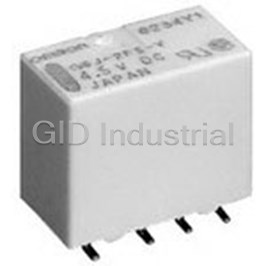
OMRON ELECTRONIC COMPONENTS G6J-2FL-Y-TR-DC4.5
Description
Electromechanical Relay 4.5VDC 137.9Ohm 1A DPDT (10.6x7.4x10)mm SMD Ultra-Compact and Slim Relay
G6J-2FL-Y-TR-DC4.5
Part Number
G6J-2FL-Y-TR-DC4.5
Price
Request Quote
Manufacturer
OMRON ELECTRONIC COMPONENTS
Lead Time
Request Quote
Category
Circuit Protection » Electromechanical Relay
Specifications
Manufacturer
Omron Electronic Components
Manufacturers Part #
G6J-2FL-Y-TR-DC4.5
Industry Aliases
G6J-2FL-Y-TR DC4.5
Sub-Categories
Electromechanical Relays
Selling Alternatives
G6J-2FL-Y-TRDC4.5BYOMR
Factory Pack Quantity
800
Datasheet

Extracted Text
Surface-mounting Relay G6J-Y Ultra-compact and Slim DPDT Relay n Dimensions of 5.7 × 10.6 × 9 mm (W × L × H) represent a reduction of approximately 56% in mounting area compared with the OMRON G6S, for higher-density mounting. n Dielectric strength of 1,500 VAC and an impulse withstand voltage of 2,500 V for 2 × 10 μs (conforms to North American Telcordia specifications (formerly Bellcore)). n Conforms to FCC Part 68 (i.e., impulse withstand voltage of 1,500 V for 10 × 160 μs between coil and contacts and between contacts of the same polarity). n Single-winding latching models to save energy. n Conforms to UL60950 (File No. E41515)/CSA C22.2 No. 60950 (File No. LR31928). Refer to pages 16 to 17 for details. RoHS Compliant Ordering Information Classification Single-side stable Single-winding latching DPDT Plastic sealed PCB terminal G6J-2P-Y G6JU-2P-Y Surface mount terminal Short G6J-2FS-Y G6JU-2FS-Y Long G6J-2FL-Y G6JU-2FL-Y Note: 1. When ordering, add the rated coil voltage to the model number. Example: G6J-2P-Y 12 VDC Rated coil voltage 2. When ordering tape packing, add “-TR” to the model number. Example: G6J-2P-Y-TR 12 VDC Tape packing Be sure since “-TR” is not part of the relay model number, it is not marked on the relay case. Model Number Legend: G6J@-@@-@ 1 2 3 4 1. Relay function 3. Terminal shape None: Single-side stable relay P: PCB terminals U: Single-winding latching relay FS: Surface-mounting terminals, short 2. Contact form FL: Surface-mounting terminals, long 2: DPDT 4. Special function Y: Improved product for soldering heat resistance Application Examples Telephones, communications equipment, measurement devices, office automation machines, and audio-visual products. 81 G6J-Y G6J-Y Specifications n Standard Specifications Contact mechanism: Crossbar twin Ag (Au-alloy contact) Enclosure rating: Plastic-sealed n Coil Ratings Single-side Stable Relays (G6J-2P-Y, G6J-2FS-Y, G6J-2FL-Y) Rated voltage 3 VDC 4.5 VDC 5 VDC 12 VDC 24 VDC Rated current 48.0 mA 32.6 mA 28.9 mA 12.3 mA 9.2 mA Coil resistance 62.5 Ω 137.9 Ω 173.1 Ω 976.8 Ω 2,600.5 Ω Must operate voltage 75% max. of rated voltage Must release voltage 10% min. of rated voltage Max. voltage 150% of rated voltage Power consumption Approx. 140 mW Approx. 230 mW Note: 1. The rated current and coil resistance are measured at a coil temperature of 23°C with a tolerance of ±10%. 2. The operating characteristics are measured at a coil temperature of 23°C. 3. The maximum voltage is the highest voltage that can be imposed on the Relay coil instantaneously. Single-winding Latching Relays (G6JU-2P-Y, G6JU-2FS-Y, G6JU-2FL-Y) Rated voltage 3 VDC 4.5 VDC 5 VDC 12 VDC Rated current 33.7 mA 22.0 mA 20.4 mA 9.0 mA Coil resistance 89.0 Ω 204.3 Ω 245.5 Ω 1,329.2 Ω Must set voltage 75% max. of rated voltage Must reset voltage 75% max. of rated voltage Max. voltage 150% of rated voltage Power consumption Approx. 100 mW Note: 1. The rated current and coil resistance are measured at a coil temperature of 23°C with a tolerance of ±10%. 2. The operating characteristics are measured at a coil temperature of 23°C. 3. The maximum voltage is the highest voltage that can be imposed on the Relay coil instantaneously. n Contact Ratings Load Resistive load Rated load 0.3 A at 125 VAC, 1 A at 30 VDC Rated carry current 1 A Max. switching voltage 125 VAC, 110 VDC Max. switching current 1 A 82 G6J-Y G6J-Y n Characteristics Item Single-side Stable Relays Single-winding Latching Relays G6J-2P-Y, G6J-2FS-Y, G6J-2FL-Y G6JU-2P-Y, G6JU-2FS-Y, G6JU-2FL-Y Contact resistance (See note 1.) 100 mΩ max. Operating (set) time (See note 2.) 3 ms max. (approx. 1.6 ms) Release (reset) time (See note 2.) 3 ms max. (approx. 1.0 ms) 3 ms max. (approx. 0.9 ms) Minimum set/reset signal width --- 10 ms Insulation resistance (See note 3.) 1,000 MΩ min. (at 500 VDC) Dielectric Coil and contacts 1,500 VAC, 50/60 Hz for 1 min strength Contacts of 1,000 VAC, 50/60 Hz for 1 min different polarity Contacts of 750 VAC, 50/60 Hz for 1 min same polarity Impulse Coil and contacts 2,500 VAC, 2 x 10 μs withstand Contacts of 1,500 VAC, 10 x 160 μs voltage different polarity Contacts of same polarity Vibration resistance Destruction: 10-55-10 Hz 2.5-mm single amplitude (5-mm double amplitude) Malfunction: 10-55-10 Hz 1.65-mm single amplitude (3.3-mm double amplitude) 2 Shock resistance Destruction: 1,000 m/s (approx. 100G) 2 Malfunction: 750 m/s (approx. 75G) Life expectancy Mechanical: 50,000,000 operations min. (at 36,000 operations/hour) Electrical: 100,000 operations min. (with a rated load at 1,800 operations/hour) Failure rate (P level) (See note 4.) 10 μA at 10 mVDC Ambient temperature −40 to 85°C (with no icing or condensation) Ambient humidity 5% to 85% Weight Approx. 1.0 g Note: The above values are initial values. Note: 1. The contact resistance was measured with 10 mA at 1 VDC with a fall-of-potential method. 2. Values in parentheses are actual values. 3. The insulation resistance was measured with a 500-VDC Megger Tester applied to the same parts as those for checking the dielectric strength. 4. This value was measured at a switching frequency of 120 operations/min and the criterion of contact resistance is 50 Ω. This value may vary depending on the operating frequency, operating conditions, expected reliability level of the relay, etc. Always double-check relay suitability under actual load conditions. 83 G6J-Y G6J-Y Engineering Data Maximum Switching Capacity Ambient Temperature vs. Ambient Temperature Maximum Voltage vs. Switching Current 10 250 1.2 7 5 1 200 3 0.8 150 AC resistive load 1 0.6 0.7 100 0.5 DC resistive load 0.4 0.3 50 0.2 0 0.1 0 1 3 5 10 30 50 100 300 500 1,000 −40 −20 0 20 40 60 80 100 −40 −20 0 20 40 60 80 100 Switching voltage (V) Ambient temperature (°C) Ambient temperature (°C) Note: “Maximum voltage” is the maximum voltage that can be applied to the Relay coil. Electrical Endurance Ambient Temperature vs. Must Shock Malfunction Operate or Must Release Voltage Y 100 1,000 1,000 Maximum estimated value Energized 90 500 max. 800 avg. 300 80 min. 600 X Not Z 1,000 energized 1,000 70 400 100 30 VDC resistive load Ambient temperature: 23°C 200 60 Switching frequency: 50 1,800 operations/hour 50 30 200 40 400 max. 1,000 1,000 10 30 avg. Z' X' 600 125 VAC resistive load min. Ambient temperature: 23°C Shock directions 5 800 20 Switching frequency: X X' 3 1,800 operations/hour Y 2 10 Operating voltage 1,000 Unit: m/s Z Y' Release voltage Sample: G6J-2P-Y 0 Z' 1 Number of Relays: 10 −60 −40 −20 0 20 40 60 80 100 0 0.2 0.4 0.6 0.8 1 1.2 Y' Ambient temperature (°C) Switching current (A) Conditions: Shock is applied in ±X, ±Y, and ±Z directions three times each with and without energizing the Relays to check the number of contact malfunctions. Electrical Endurance (with Contact Reliability Test Electrical Endurance (Contact Operate and Release Voltage) (See notes 1 and 2.) resistance) (See note 1.) (See note 1.) 100 1,000 Sample: G6J-2P-Y 1,000 Sample: G6J-2P-Y Number of Relays: 10 NO contact Sample: G6J-2P-Y NO contact Number of Relays: 10 Test conditions: 1-A resistive load at Number of Relays: 10 Test conditions: 1-A resistive load 30 VDC with an operation rate of 50% Test conditions: 10 μA resistive load NC contact 500 NC contact at 30 VDC with an operation rate Switching frequency: 1,800 operations/hour 500 at 10 m VDC with an operation rate 80 of 50% Switching frequency: of 50% Switching frequency: 7,200 max. 1,800 operations/hour operations/hour 300 300 min. Operate voltage 60 100 100 max. max. 40 max. max. 50 max. 50 min. min. min. Release voltage min. min. 30 Contact resistance 30 Contact resistance 20 0 10 10 0.001 0.01 0.1 1 10 100 1,000 0.001 0.01 0.1 1 10 100 1,000 0.001 0.01 0.1 1 10 100 1,000 3 3 5 Operating frequency (x10 operations) Operating frequency (x10 operations) Operating frequency (x10 operations) Note: 1. The tests were conducted at an ambient temperature of 23°C. 2. The contact resistance data are periodically measured reference values and are not values from each monitoring operation. Contact resistance values will vary according to the switching frequency and operating environment, so be sure to check operation under the actual operating conditions before use. 84 4 Switching current (A) On the basis of rated voltage (%) Switching operations (x10 operations) Contact resistance (mΩ) Maximum voltage (%) Change rate on the basis of rated voltage (%) Contact resistance (mΩ) Switching current (A) G6J-Y G6J-Y Mutual Magnetic Interference Mutual Magnetic Interference Initial Installed in flush Initial Installed in flush stage configuration stage configuration +30 +30 +20 +20 +10 +10 Sample Sample 0 0 −10 −10 Not energized −20 −20 Average Average value value Not energized −30 −30 Initial Installed in flush Initial Installed in flush stage configuration stage configuration +30 +30 +20 +20 +10 +10 Sample 0 Sample 0 −10 −10 Energized −20 −20 Average Average value value −30 −30 Energized Operate voltage Operate voltage Release voltage Release voltage External Magnetic Interference Average value Average value Average value +30 +30 +30 S N S N S N +20 +20 +20 +10 +10 +10 0 0 0 −10 −10 −10 −20 −20 −20 Sample: G6J-2P-Y Operate voltage Sample: G6J-2P-Y Operate voltage Sample: G6J-2P-Y Operate voltage Number of Relays: 5 Release voltage Number of Relays: 5 Release voltage Number of Relays: 5 Release voltage −30 −30 −30 −1,200 −800 −400 0 400 800 1,200 −1,200 −800 −400 0 400 800 1,200 −1,200 −800 −400 0 400 800 1,200 External magnetic field (A/m) External magnetic field (A/m) External magnetic field (A/m) High-frequency Characteristics High-frequency Characteristics High-frequency Characteristics (Return Loss, V.SWR) (See notes (Isolation) (See notes 1 and 2.) (Insertion Loss) (See notes 1 and 2.) 1 and 2.) Average value Average value Average value 0 3.5 0 0 10 10 3 20 0.5 1 pole 20 2.5 30 2-pole return loss 2 poles 40 1 30 2 2 poles 1-pole return loss 50 1 pole 40 1.5 60 1.5 70 50 1 2-pole V.SWR 2 80 1-pole V.SWR 60 0.5 90 70 0 2.5 100 1 10 100 1,000 1 10 100 1,000 1 10 100 1,000 Frequency (MHz) Frequency (MHz) Frequency (MHz) Note: 1. The tests were conducted at an ambient temperature of 23°C. 2. High-frequency characteristics depend on the PCB to which the Relay is mounted. Always check these characteristics, in- cluding endurance, in the actual machine before use. 85 Isolation (dB) Change rate on the basis of initial value (%) Change rate on the Change rate on the basis of initial value (%) basis of initial value (%) Insertion Loss (dB) Change rate on the basis of initial value (%) Change rate on the Change rate on the basis of initial value (%) basis of initial value (%) Return loss (dB) Change rate on the basis of initial value (%) V.SWR G6J-Y G6J-Y Operate and Release Bounce Vibration Resistance Operate and Release Time Time Distribution (See note.) Distribution (See note.) 40 40 5.0 Sample: G6J-2P-Y Operate time Operate bounce time Number of Relays: 30 4.0 35 35 Release time Release bounce time 3.0 30 30 2.0 25 25 1.0 Operate voltage 20 20 0.0 −1.0 15 15 Release voltage −2.0 10 10 −3.0 5 5 Sample: G6J-2P-Y −4.0 Number of Relays: 30 −5.0 0 0.5 1 1.5 2 2.5 3 0 0.5 1 1.5 2 2.5 3 Initial After Time (ms) Time (ms) Note: The tests were conducted at an ambient temperature of 23°C. 86 Number of contacts Number of contacts Change rate on the basis of rated value (%) G6J-Y G6J-Y Dimensions Note: All units are in millimeters unless otherwise indicated. Terminal Arrangement/ G6J-2P-Y Mounting Dimensions Internal Connections (Bottom View) G6JU-2P-Y (Bottom View) 10.6 5.7 Tolerance ±0.1 mm G6J-2P-Y 7.6 Eight, 0.85-dia. Orientation mark 5.4 holes 9 3.2 1 2 3 4 + 3.2 3.5 0.3 − 1.5 0.4 0.15 (1.5) 8 7 6 5 (1.25) 3.2 3.2 5.4 G6JU-2P-Y Note: Each value has a tolerance of ±0.3 mm. 7.6 Orientation mark 1 2 3 4 + − S R − + 8 7 6 5 G6J-2FS-Y Terminal Arrangement/ Mounting Dimensions G6JU-2FS-Y Internal Connections (Top View) (Top View) Tolerance ±0.1 mm G6J-2FS-Y 7.6 10.6 5.7 5.4 Orientation mark 2.35 3.2 8 7 6 5 10.0 max. − 4.35 + 1.5 0.4 3.2 0.8 1 2 3 4 3.2 5.7 (1.5) 5.4 G6JU-2FS-Y Note: Each value has a tolerance of ±0.3 mm. 7.6 Orientation mark 8 7 6 5 − + S R + − 1 2 3 4 Mounting Dimensions Terminal Arrangement/ G6J-2FL-Y (Top View) Internal Connections G6JU-2FL-Y (Top View) Tolerance ±0.1 mm G6J-2FL-Y 7.6 10.6 5.7 Orientation mark 5.4 3.2 3.2 8 7 6 5 − 10.0 max. 5.2 + 1 2 3 4 1.5 0.4 3.2 0.8 3.2 7.4 (1.5) 5.4 G6JU-2FL-Y 7.6 Note: Each value has a tolerance of ±0.3 mm. Orientation mark 8 7 6 5 − + S R + − 1 2 3 4 87 G6J-Y G6J-Y Stick Packing and Tape Packing Carrier Tape Dimensions 1. Stick Packing Relays in stick packing are arranged so that the orientation mark G6J-2FS-Y, G6JU-2FS-Y of each Relay is on the left side. 10.2±0.1 16±0.1 Always confirm that the Relays are in the correct orientation when +0.1 1.5 dia. 0.1 1.75± 2±0.1 4±0.1 0 0.4±0.05 B A mounting the Relays to the PCBs. Orientation of Relays 11.5±0.1 Stopper (gray) Stopper (green) 0.2 24± 11.1±0.1 6.3±0.1 5° max. B-B Cross Section B Stick length: 555 mm (stopper not included) A 0.1 0.1 6.2± 8.3± No. of Relays per stick: 50 5° max. 5° max. 2. Tape Packing (Surface-mounting Terminal A-A Cross Section Relays) G6J-2FL-Y, G6JU-2FL-Y When ordering Relays in tape packing, add the prefix “-TR” to the 0.1 model number, otherwise the Relays in stick packing will be 10.2± 0.1 16± provided. +0.1 1.5 dia. 1.75±0.1 0.1 0.1 0 0.05 2± 4± B 0.4± A Tape type: TB2412R (EIAJ (Electronic Industrial Association of Japan)) 0.1 11.5± Reel type: R24D (EIAJ (Electronic Industrial Association 24±0.2 11.1±0.1 6.3±0.1 of Japan)) Relays per reel: 400 5° max. B B-B Cross Section Direction of Relay Insertion A Pulling Direction 0.1 7.9± 0.1 10± Orientation mark 5° max. 5° max. Top tape (cover tape) Pulling A-A Cross Section direction Carrier tape Embossed tape Reel Dimensions 0.5 25.5± 29.5±1 13±0.2 dia. 0.5 21± dia. 2±0.5 A 330 80 R1 Enlarged View of Section A 88 G6J-Y G6J-Y Recommended Soldering Method • The thickness of cream solder to be applied should be between IRS Method (for Surface-mounting Terminal 150 and 200 μm on OMRON's recommended PCB pattern. Relays) • In order to perform correct soldering, it is recommended that the correct soldering conditions be maintained as shown below on the left-hand side. Correct Soldering Incorrect Soldering Top of cover (Peak): 255°C max. Soldering Excessive Relay Insufficient 250 max. amount of amount of 230 solder Terminal solder Solder PCB Land 180 Visually check that the Relay is properly soldered. Preheating 150 Surface of the relay terminal 120 max. 30 max. Time (s) Note: Temperatures are given for the surface of the terminal. n Approved Standards UL approval: UL60950 (File No. E41515) CSA approval: C22.2 No. 60950 (File No. LR31928) Contact form Coil rating Contact rating Number of test operations DPDT G6J-2P-Y, 2FS-Y, 2FL-Y: 3 to 24 VDC 1 A at 30 VDC 6,000 G6JU-2P-Y, 2FS-Y, 2FL-Y: 3 to 24 VDC 0.5 A at 60 VDC 0.3 A at 125 VAC 89 Temperature (°C) G6J-Y G6J-Y Precautions Refer to page 25 for information on general precautions. Be sure to read these precautions before using the Relay. Mounting Latching Relays Correct Use Make sure that the vibration or shock that is generated from other • Long Term Current Carrying devices, such as Relays in operation, on the same panel and Under a long-term current carrying without switching, the imposed on the Latching Relays does not exceed the rated value, insulation resistance of the coil goes down gradually due to the otherwise the Latching Relays that have been set may be reset or heat generated by the coil itself. Furthermore, the contact vice versa. The Latching Relays are reset before shipping. If resistance of the Relay will gradually become unstable due to the excessive vibration or shock is imposed, however, the Latching generation of film on the contact surfaces. A Latching Relay can Relays may be set accidentally. Be sure to apply a reset signal be used to prevent these problems. When using a single-side before use. stable relay, the design of the fail-safe circuit provides protection against contact failure and open coils. Maximum Voltage Handling of Surface-mounting Relays The maximum voltage of the coil can be obtained from the coil temperature increase and the heat-resisting temperature of coil Use the Relay as soon as possible after opening the moisture- insulating sheath material. (Exceeding the heat-resisting proof package. If the Relay is left for a long time after opening the temperature may result in burning or short-circuiting.) The moisture-proof package, the appearance may suffer and seal maximum voltage also involves important restrictions which failure may occur after the solder mounting process. To store the include the following: Relay after opening the moisture-proof package, place it into the original package and sealed the package with adhesive tape. • Must not cause thermal changes or deterioration of the insulating material. When washing the product after soldering the Relay to a PCB, use a water-based solvent or alcohol-based solvent, and keep the • Must not cause damage to other control devices. solvent temperature to less than 40°C. Do not put the relay in a • Must not cause any harmful effect on people. cold cleaning bath immediately after soldering. • Must not cause fire. Soldering Therefore, be sure not to exceed the maximum voltage specified Soldering temperature: Approx. 250°C (At 260°C if the DWS in the catalog. method is used.) As a rule, the rated voltage must be applied to the coil. A voltage Soldering time: Approx. 5 s max. (Approx. 2 s for the first time and exceeding the rated value, however, can be applied to the coil approx. 3 s for the second time if the DWS method is used.) provided that the voltage is less than the maximum voltage. It must be noted that continuous voltage application to the coil will Be sure to adjust the level of the molten solder so that the solder cause a coil temperature increase thus affecting characteristics will not overflow onto the PCB. such as electrical life and resulting in the deterioration of coil Claw Securing Force During Automatic Insertion insulation. During automatic insertion of Relays, make sure to set the Coating securing force of the claws to the following values so that the Relays mounted on PCBs may be coated or washed. Do not Relay characteristics will be maintained. apply silicone coating or detergent containing silicone, otherwise C the silicone coating or detergent may remain on the surface of the B A Relays. Other Handling Please don’t use the relay if it suffered the dropping shock. Because there is a possibility of something damage for initial performance. Direction A: 4.90 N max. Direction B: 9.80 N max. Direction C: 9.80 N max. Secure the claws to the area indicated by shading. Do not attach them to the center area or to only part of the Relay. Environmental Conditions During Operation, Storage, and Transportation Protect the Relays from direct sunlight and keep the Relays under normal temperature, humidity, and pressure. ALL DIMENSIONS SHOWN ARE IN MILLIMETERS. To convert millimeters into inches, multiply by 0.03937. To convert grams into ounces, multiply by 0.03527. Cat. No. K125-E1-02 90
Frequently asked questions
How does Electronics Finder differ from its competitors?

Is there a warranty for the G6J-2FL-Y-TR-DC4.5?
Which carrier will Electronics Finder use to ship my parts?
Can I buy parts from Electronics Finder if I am outside the USA?
Which payment methods does Electronics Finder accept?
Why buy from GID?

Quality
We are industry veterans who take pride in our work

Protection
Avoid the dangers of risky trading in the gray market

Access
Our network of suppliers is ready and at your disposal

Savings
Maintain legacy systems to prevent costly downtime

Speed
Time is of the essence, and we are respectful of yours
Related Products
Electromechanical Relay 12VDC 360Ohm 8ADC/10AAC SPDT (22.5x16.5x19)mm THT Power Relay G5LE-14-ACDDC1...
Electromechanical Relay 24VDC 1.44KOhm 8ADC/10AAC SPDT (22.5x16.5x19)mm THT Power Relay G5LE-14-ACDD...
Electromechanical Relay 24VDC 1.6KOhm 8ADC/10AAC SPDT (22.5x16.5x19)mm THT Power Relay
POWER RELAYS PCB POWER RELAY G6B-2214P-1-US-DC5
POWER RELAYS PCB POWER RELAY G6D-1A-ASI-NPDC24
Electromechanical Relay 4.5VDC 194Ohm 1A DPDT (10x6.5x5.2)mm SMD Signal Relay G6K-2FDC4.5
Request a Quote

The quote request has been received
Close

Facing challenges or have inquiries? Feel free to contact us!
Call Us +1-469-283-2440
What they say about us
FANTASTIC RESOURCE
One of our top priorities is maintaining our business with precision, and we are constantly looking for affiliates that can help us achieve our goal. With the aid of GID Industrial, our obsolete product management has never been more efficient. They have been a great resource to our company, and have quickly become a go-to supplier on our list!
Bucher Emhart Glass
EXCELLENT SERVICE
With our strict fundamentals and high expectations, we were surprised when we came across GID Industrial and their competitive pricing. When we approached them with our issue, they were incredibly confident in being able to provide us with a seamless solution at the best price for us. GID Industrial quickly understood our needs and provided us with excellent service, as well as fully tested product to ensure what we received would be the right fit for our company.
Fuji
HARD TO FIND A BETTER PROVIDER
Our company provides services to aid in the manufacture of technological products, such as semiconductors and flat panel displays, and often searching for distributors of obsolete product we require can waste time and money. Finding GID Industrial proved to be a great asset to our company, with cost effective solutions and superior knowledge on all of their materials, it’d be hard to find a better provider of obsolete or hard to find products.
Applied Materials
CONSISTENTLY DELIVERS QUALITY SOLUTIONS
Over the years, the equipment used in our company becomes discontinued, but they’re still of great use to us and our customers. Once these products are no longer available through the manufacturer, finding a reliable, quick supplier is a necessity, and luckily for us, GID Industrial has provided the most trustworthy, quality solutions to our obsolete component needs.
Nidec Vamco
TERRIFIC RESOURCE
This company has been a terrific help to us (I work for Trican Well Service) in sourcing the Micron Ram Memory we needed for our Siemens computers. Great service! And great pricing! I know when the product is shipping and when it will arrive, all the way through the ordering process.
Trican Well Service
GO TO SOURCE
When I can't find an obsolete part, I first call GID and they'll come up with my parts every time. Great customer service and follow up as well. Scott emails me from time to time to touch base and see if we're having trouble finding something.....which is often with our 25 yr old equipment.
ConAgra Foods