

 Manufacturers
OMRON ELECTRONIC COMPONENTS P6B-Y1
Description
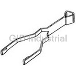
Removal Tool for Power PCB Relay
P6B-Y1
Part Number
P6B-Y1
Price
Request Quote
Manufacturer
OMRON ELECTRONIC COMPONENTS
Lead Time
Request Quote
Category
Fasteners, Hardware and Fluid Transfer » Hardware Tools
Specifications
Manufacturer
Omron Electronic Components
Manufacturers Part #
P6B-Y1
Industry Aliases
P6B-Y1
Sub-Category
Hardware Tools
Factory Pack Quantity
100
Datasheet

Extracted Text
G6B PCB Power Relay High Capacity and High Dielectric Strength Miniature Relay with Fully Sealed Construction in 5 A (8 A) SPST-NO(1a), SPST-NO+SPST-NC(1a1b), DPST-NO(2a), DPST-NC(2b) Types • P6B model for connecting sockets are available. • High insulation with dielectric strength of 3,000VAC between coil and contacts (impulse withstand voltage of 6 kV). G • Standard model conforms to UL/CSA standards. 6 B • AgSnIn contacts suitable for loads that generate surge voltage (inductive load, capacity load, etc.) are available. (-FD type) • Ultrasonic cleanable models are available. (-U type) • Operation indicator & built-in surge absorption diode models are available. (-ND type) • 2-Pole type available. • High-reliability models are available. G6B-1184P-US model (The relay used in Terminal Relay G6B-48BND) ■Application Examples RoHS Compliant • Ideal for output applications of control equipments ■Model Number Legend G6B@-@@@@@-@--@-@-@-@-@ 12 3 4 5 6 7 8 9 10 11 1. Relay Function 4. Enclosure rating 8. Operation Indicator Diode None: Single-side stable 4: Fully sealed Availability U : Single-winding latching 7: Flux protection None: Standard (G6B@-1114 models only) ND : Operation indicator & coil surge 5. Terminal Shape K : Double-winding latching absorption diode P: Straight PCB terminals (G6B@-1114 models only) (for -1177 type only) Socket mounting terminals 2. Contact Form C: Self-clinching PCB 9. Approved Standards 21: SPST-NO + SPST-NC US: UL/CSA 6. Contact material 22: DPST-NO None: Standard (Ag-alloy (Cd free)) 10. Washability 20: DPST-NC FD : AgSnIn contact None: Standard 11: SPST-NO (Suitable for DC inductive load with U : For ultrasonically cleanable 3. Classification high inrush current) 11. Mounting 1: Standard 7. Coil Polarity None: Mounted directly to PCB 7: High-capacity None: 5, 6 Terminal (+), 1, 2 Terminal (-) P6B : Mounted to Socket 8: Single crossbar 1 : 5, 6 Terminal (-), 1, 2 Terminal (+) 1 G6B PCB Power Relay ■Ordering Information ●Standard Models (UL, CSA certified) Contact material Standard (Ag-alloy (Cd free)) AgSnIn contact Minimum Number packing unit of poles Relay Function Contact form Terminals Model Rated coil voltage Model Rated coil voltage Straight PCB G6B-1114P-US 5, 6, 12, 24 VDC G6B-1114P-FD-US 5, 6, 12, 24 VDC SPST-NO (1a) 100 Self-clinching (Standard) pcs/tray G6B-1114C-US 5, 6, 12, 24 VDC G6B-1114C-FD-US 12, 24 VDC PCB Straight PCB G6B-1174P-US 5, 6, 12, 24 VDC G6B-1174P-FD-US 5, 6, 12, 24 VDC Single-side SPST-NO (1a) 20 Self-clinching stable (High-capacity) pcs/tube G6B-1174C-US 5, 12, 24 VDC G6B-1174C-FD-US 5, 12, 24 VDC PCB Straight PCB G6B-1184P-US 5, 12, 24 VDC --- --- SPST-NO (1a) Self-clinching (High-reliability ) --- --- --- --- PCB 1-pole Straight PCB G6BU-1114P-US 5, 6, 12, 24 VDC G6BU-1114P-FD-US 5, 12, 24 VDC Single-winding SPST-NO (1a) Self-clinching latching (Standard) G6BU-1114C-US 12 VDC --- --- PCB Straight PCB G6BK-1114P-US 5, 6, 12, 24 VDC G6BK-1114P-FD-US 5, 6, 12, 24 VDC Double-winding SPST-NO (1a) Self-clinching latching (Standard) G6BK-1114C-US 5, 6, 12, 24 VDC G6BK-1114C-FD-US 24 VDC PCB SPST-NO (1a) Straight PCB G6B-1177P-ND-US 5, 12, 24 VDC G6B-1177P-FD-ND-US 5, 12, 24 VDC Single-side (Built-in high- 100 Self-clinching stable capacity operation pcs/tray G6B-1177C-ND-US 5, 12, 24 VDC G6B-1177C-FD-ND-US 12, 24 VDC PCB indicator & diode) G Straight PCB G6B-2114P-US 5, 6, 12, 24 VDC G6B-2114P-FD-US 5, 6, 12, 24 VDC SPST-NO (1a)+ 6 SPST-NC (1b) Self-clinching G6B-2114C-US 5, 12, 24 VDC G6B-2114C-FD-US 5, 12 VDC B (Standard) PCB Straight PCB G6B-2214P-US 5, 6, 12, 24 VDC G6B-2214P-FD-US 5, 6, 12, 24 VDC Single-side DPST-NO (2a) 2-pole Self-clinching stable (Standard) G6B-2214C-US 5, 12, 24 VDC G6B-2214C-FD-US 5, 12, 24 VDC PCB Straight PCB G6B-2014P-US 5, 6, 12, 24 VDC G6B-2014P-FD-US 5, 6, 12, 24 VDC DPST-NC (2b) Self-clinching (Standard) G6B-2014C-US 5, 6, 12, 24 VDC G6B-2014C-FD-US 12, 24 VDC PCB Note: AgSnIn contact models are highly welding-resistant, and roughening of contacts due to inrush current and inductive load is lessened. ●Models for Reverse Coil Polarity Contact material Standard (Ag-alloy (Cd free)) AgSnIn contact Minimum Number packing unit of poles Relay Function Contact form Terminals Model Rated coil voltage Model Rated coil voltage Straight PCB G6B-1114P-1-US 5, 6, 12, 24 VDC G6B-1114P-FD-1-US 24 VDC SPST-NO (1a) 100 Self-clinching (Standard) pcs/tray --- --- --- --- PCB Single-side stable Straight PCB G6B-1174P-1-US 5, 12, 24 VDC --- --- SPST-NO (1a) 20 Self-clinching (High-capacity) pcs/tube --- --- --- --- PCB 1-pole Straight PCB G6BU-1114P-1-US 5, 12 VDC --- --- Single-winding SPST-NO (1a) Self-clinching latching (Standard) --- --- --- --- PCB Straight PCB G6BK-1114P-1-US 5, 6, 12, 24 VDC --- --- Double-winding SPST-NO (1a) Self-clinching latching (Standard) --- --- --- --- PCB 100 pcs/tray Straight PCB G6B-2114P-1-US 5, 6, 12, 24 VDC G6B-2114P-FD-1-US 12, 24 VDC SPST-NO (1a)+ SPST-NC (1b) Self-clinching --- --- --- --- (Standard) PCB Single-side 2-pole stable Straight PCB G6B-2214P-1-US 5, 12, 24 VDC --- --- DPST-NO (2a) Self-clinching (Standard) --- --- --- --- PCB Note: AgSnIn contact models are highly welding-resistant, and roughening of contacts due to inrush current and inductive load is lessened. 2 G6B PCB Power Relay ●Models for Ultrasonically Cleanable Contact material Standard (Ag-alloy (Cd free)) AgSnIn contact Minimum Number packing unit of poles Relay Function Contact form Terminals Model Rated coil voltage Model Rated coil voltage Straight PCB G6B-1114P-US-U 5, 6, 12, 24 VDC G6B-1114P-FD-US-U 6, 12, 24 VDC Single-side SPST-NO (1a) Self-clinching stable (Standard) G6B-1114C-US-U 5, 12, 24 VDC --- --- PCB Straight PCB G6BU-1114P-US-U 24 VDC --- --- Single-winding SPST-NO (1a) 1-pole Self-clinching latching (Standard) --- --- --- --- PCB Straight PCB G6BK-1114P-US-U 5, 6, 12, 24 VDC G6BK-1114P-FD-US-U 12, 24 VDC Double-winding SPST-NO (1a) Self-clinching latching (Standard) G6BK-1114C-US-U 24 VDC --- --- PCB 100 pcs/tray Straight PCB G6B-2114P-US-U 5, 12, 24 VDC G6B-2114P-FD-US-U 5, 12, 24 VDC SPST-NO (1a)+ SPST-NC (1b) Self-clinching --- --- --- --- (Standard) PCB Straight PCB G6B-2214P-US-U 5, 6, 12, 24 VDC G6B-2214P-FD-US-U 5, 12, 24 VDC Single-side DPST-NO (2a) 2-pole Self-clinching stable (Standard) G6B-2214C-US-U 12, 24 VDC --- --- PCB Straight PCB G6B-2014P-US-U 5, 12, 24 VDC G6B-2014P-FD-US-U 5, 12, 24 VDC DPST-NC (2b) Self-clinching (Standard) --- --- --- --- PCB Note: When ordering, add the rated coil voltage to the model number. Example: G6B-1114P-US DC5 Rated coil voltage G However, the notation of the coil voltage on the product case as well as on the packing will be marked as @@ VDC. 6 B ●Connecting Sockets (Sold Separately) Applicable relay Model Minimum ordering unit G6B-1114P(-FD)-US-P6B G6B-1174P(-FD)-US-P6B P6B-04P G6B-1177P(-FD)-ND-US-P6B G6BU-1114P-US-P6B 20 pcs G6BK-1114P-US-P6B P6B-06P G6B-2114P-US-P6B G6B-2214P-US-P6B P6B-26P G6B-2014P-US-P6B Removal Tool P6B-Y1 1 pcs Hold-down Clips P6B-C2 Note 1. G6B-1174P-US-P6B and G6B-1177P-ND-US-P6B are rated for 8 A when mounted on a PCB. However, when used with the P6B-04P socket models, the allowable current is derated to 5 A. 2.The P6B sockets are designed to be used with G6B-@@@@P(-FD)-US-P6B relays. Only use G6B relays that include "-P6B" in their model numbers with the sockets. Do not use standard G6B's that omit "-P6B" from their model numbers with the sockets. 3.The hold-down clips of the P6B-C2 model are not suitable for the G6B-1174P and G6B-1177P models since they have different heights. 4.Products with UL/CSA certification marks will be supplied for orders of standard models. 3 G6B PCB Power Relay ■Ratings ●Coil: 1-Pole, Single-side Stable Type (Including models for ultrasonically cleanable) Must operate Must release Max. voltage Item Rated current Coil resistance Power consumption voltage (V) voltage (V) (V) (mA) (Ω) (mW) Rated voltage % of rated voltage 5 VDC 40 125 6 VDC 33.3 180 160% 70% max. 10% min. Approx. 200 (at 23°C) 12 VDC 16.7 720 24 VDC 8.3 2,880 ●Coil: 2-Pole, Single-side Stable Type (Including models for ultrasonically cleanable) Must operate Must release Max. voltage Item Rated current Coil resistance Power consumption voltage (V) voltage (V) (V) (mA) (Ω) (mW) Rated voltage % of rated voltage 5 VDC 60 83.3 6 VDC 50 120 140% 80% max. 10% min. Approx. 300 (at 23°C) 12 VDC 25 480 24 VDC 12.5 1,920 ●Coil: Single-winding Latching Type (Including models for ultrasonically cleanable) Must set Must reset Max. voltage Item Power consumption Rated Coil voltage (V) voltage (V) (V) current resistance Set coil Reset coil (mA) (Ω) % of rated voltage Rated voltage (mW) (mW) 5 VDC 40 125 G 6 6 VDC 33.3 180 160% 70% max. 70% max. 200 200 B (at 23°C) 12 VDC 16.7 720 24 VDC 8.3 2,880 ●Coil: Double-winding Latching Type (Including models for ultrasonically cleanable) Must set voltage Must reset voltage Max. voltage Rated current (mA) Coil resistance (Ω) Power consumption Item (V) (V) (V) Set coil Reset coil Rated voltage Set coil Reset coil Set coil Reset coil % of rated voltage (mW) (mW) 5 VDC 56 56 89.2 89.2 6 VDC 46.8 46.8 128.5 128.5 130% 70% max. 70% max. 280 280 (at 23°C) 12 VDC 23.3 23.3 515 515 24 VDC 11.7 11.7 2,060 2,060 ●Coil: Operation Indicator Model (Flux-resistant type. Do not wash down with water.) Must operate Must release Max. voltage Item Rated current Coil resistance Power consumption voltage (V) voltage (V) (V) (mA) (Ω) (mW) Rated voltage % of rated voltage 5 VDC 43 116 Approx. 200 130% 12 VDC 19.7 610 70% max. 10% min. Approx. 240 (at 23°C) 24 VDC 11.3 2,120 Approx. 275 Note 1. The rated current and coil resistance are measured at a coil temperature of 23°C with a tolerance of ±10%. 2.The operating characteristics are measured at a coil temperature of 23°C. 3.The “Max. voltage” is the maximum voltage that can be applied to the relay coil. ●Contacts G6B-1114P(-FD)(-1)-US G6B-2114P(-FD)(-1)-US G6BU-1114P(-FD)(-1)-US G6B-1174P(-FD)(-1)-US G6B-2214P(-FD)(-1)-US G6BK-1114P(-FD)(-1)-US G6B-1177P(-FD)-ND-US G6B-2014P(-FD)-US Model G6B-1184P-US G6B-1114C(-FD)-US G6B-1174C(-FD)-US G6B-2114C(-FD)-US G6BU-1114C-US G6B-1177C(-FD)-ND-US G6B-2214C(-FD)-US G6BK-1114C(-FD)-US G6B-2014C(-FD)-US Load Inductive load Inductive load Inductive load Inductive load Resistive load Resistive load Resistive load Resistive load Item (cosφ = 0.4; L/R = 7 ms) (cosφ = 0.4; L/R = 7 ms) (cosφ = 0.4; L/R = 7 ms) (cosφ = 0.4; L/R = 7 ms) Contact type Single Single crossbar Single Contact material Ag-Alloy (Cd free) Au-alloy + Ag (Cd free) Ag-Alloy (Cd free) 5 A (3 A) at 250 VAC 2 A (2 A) at 250 VAC 8 A (5 A) at 250 VAC 2 A (2 A) at 250 VAC 2 A at 250 VAC 0.5 A at 250 VAC 5 A (3 A) at 250 VAC 1.5 A (1.5 A) at 250 VAC Rated load 5 A (3 A) at 30 VDC 2 A (2 A) at 30 VDC 8 A (5 A) at 30 VDC 2 A (2 A) at 30 VDC 2 A at 30 VDC 0.5 A at 30 VDC 5 A (3 A) at 30 VDC 1.5 A (1.5 A) at 30 VDC Rated carry current 5 A (5 A) 8 A (5 A) 2A 5 A (5 A) Max. switching voltage 380 VAC, 125 VDC Max. switching current 5 A (5 A) 8 A (5 A) 2A 5 A (5 A) Note 1. The values in the parentheses ( ) are for -FD models only. 2.Use the -FD type for inductive load and switching load which contact roughening is small. 4 G6B PCB Power Relay ■Characteristics G6B-2114P(-FD)(-1)-US G6B-1114P(-FD)(-1)-US G6B-2214P(-FD)(-1)-US G6B-1174P(-FD)(-1)-US G6BU-1114P(-FD)(-1)-US G6BK-1114P(-FD)(-1)-US G6B-1177P(-FD)-ND-US G6B-2014P(-FD)(-1)-US Model G6B-1184P-US G6B-1114C(-FD)-US G6BU-1114C-US G6BK-1114C(-FD)-US G6B-1177C(-FD)-ND-US G6B-2114C(-FD)-US G6B-1174C(-FD)-US G6B-2214C(-FD)-US G6B-2014C(-FD)-US Single-winding Double-winding Built-in operation indicator Item Classification Single-side stable Single-side stable Single-side stable latching latching & surge absorption diode Contact resistance *1 30 mΩ max. 50 mΩ max. 30 mΩ max. Operate (set) time 10 ms max. Release (reset) time 10 ms max. Min. set pulse width − 15 ms (at 23°C) − Min. reset pulse width − 15 ms (at 23°C) − Insulation resistance *2 1,000 MΩ min. Between coil and 2,000 VAC, 3,000 VAC, 50/60 Hz for 1 min 3,000 VAC, 50/60 Hz for 1 min contacts 50/60 Hz for 1 min Between contacts 1,000 VAC, 50/60 Hz for 1 min Dielectric of the same polarity strength Between contacts 2,000 VAC, − of different polarity 50/60 Hz for 1 min Between set and 250 VAC, − − reset coils 50/60 Hz for 1 min Impulse withstand voltage 6 kV 1.2 × 50 μs 4.5 kV 1.2 × 50 μs 6 kV 1.2 × 50 μs − 6 kV 1.2 × 50 μs (between coil and contacts) Destruction 10 to 55 to 10 Hz, 0.75 mm single amplitude (1.5 mm double amplitude) Vibration resistance Malfunction 10 to 55 to 10 Hz, 0.75 mm single amplitude (1.5 mm double amplitude) 2 Destruction 1,000 m/s Shock G 2 2 2 resistance Malfunction 100 m/s 300 m/s 100 m/s 6 Mechanical 50,000,000 operations min. (at 18,000 operations/hr) Durability B Electrical 100,000 operation min. (at 1,800 operations/hr under rated load) Failure rate (P level) 10 mA at 5 VDC 1 mA at 1 VDC 10 mA at 5 VDC (reference value) *3 Ambient operating temperature -25°C to 70°C (with no icing or condensation) Ambient operating humidity 5% to 85% Weight Approx. 3.5 to 4.6 g Approx. 3.5 g Approx. 3.7 g Approx. 5.4 g Approx. 3.5 g Approx. 4.5 g Note 1. The values here are initial values. 2.The G6B-1177P(-FD)-ND model is flux-resistant. Do not wash it down with water. *1. The contact resistance was measured with 1 A at 5 VDC using a voltage-drop method. *2. Measurement conditions: The insulation resistance was measured with a 500 VDC megohmmeter at the same locations as the dielectric strength was measured.(Except the location between set/reset coil) *3. This value was measured at a switching frequency of 120 operations/min. 5 G6B PCB Power Relay ■Engineering Data ●Maximum Switching Current G6B-2114P-US G6B-1114P-US G6B-1174P-US G6B-2214P-US G6B-1174P-FD-US G6B-2014P-US 40 100 100 20 50 50 30 30 G6B-2114P-FD-US 10 AC inductive load AC resistive load G6B-2214P-FD-US (cosφ = 0.4) AC resistive load G6B-2014P-FD-US 5 10 10 AC resistive 8 load 3 5 5 AC 2 inductive 3 3 load DC inductive load 2 2 cosφ = 0.4 1 (L/R = 7 ms) DC resistive load AC 1.5 AC 1 inductive 1 load resistive DC resistive load 0.5 DC resistive load load 0.5 0.5 0.3 DC inductive load 0.3 0.3 0.2 DC inductive load (L/R = 7 ms) 0.1 0.1 0.1 0 3 5 10 20 30 100 300 500 0 3 5 10 30 50 100 380 1,000 0 3 5 10 30 50 100 300 500 1,000 Switching voltage (V) Switching voltage (V) Switching voltage (V) ●Ambient Temperature vs. ●Durability Maximum Coil Voltage G6B-1114P-US G6B-2114P(-FD)-US G6B-1114P-US G6B-2114P-US G6B-1174P-US G6B-2214P(-FD)-US G6B-1174P-US G6B-2214P-US G6B-1174P-FD-US G6B-2014P(-FD)-US G6B-1174P-FD-US G6B-2014P-US 1,000 1,000 200 G G6B-2114P(-FD)-US 6 G6B-1114P-US 500 500 G6B-2214P(-FD)-US 250 VAC/30 VDC resistive load 180 B G6B-1114P-US 300 300 G6B-2014P(-FD)-US G6B-1174P-US 250 VAC/30 VDC inductive load G6B-1174P-FD-US G6B-1174P-FD-US (cosφ = 0.4, L/R = 7 ms) 250 VAC/30 VDC resistive load 160 100 100 G6B-1174P-US G6B-2114P-US 250 VAC/30 VDC G6B-2214P-US 140 50 50 resistive load G6B-2014P-US 130 30 30 250 VAC/30 VDC resistive load 120 110 10 10 Higher 100 G6B-2114P-US G6B-1114P-US G6B-2214P-US 5 capacity 5 G6B-2114P-FD-US G6B-1174P-FD-US G6B-2014P-US G6B-2214P-FD-US 3 3 G6B-1174P-US G6B-2014P-FD-US 80 250 VAC/30 VDC inductive load 250 VAC resistive load (cosφ = 0.4, L/R = 7 ms) 1 1 60 0 1 2 3 4 5 6 7 8 9 10 0 1 1.5 2 3 4 5 6 7 8 9 10 0 20 23 30 40 50 60 70 80 90 Ambient temperature (°C) Switching current (A) Switching current (A) Note: The maximum coil voltage refers to the maxi-mum value in a varying range of operating power voltage, not a continuous voltage. ●Ambient Temperature vs. Must ●Mutual Magnetic Interference Operate and Must Release Voltage G6B-1114P-US G6B-1114P-US G6B-1114P-US Must operate voltage Must operate voltage 100 Sample: Must release voltage Must release voltage Must operate voltage G6B-1114P-US Must release voltage Initial stage Initial stage Test Test Number of Relays: 5 pcs 2.54 mm +1.0 +1.0 max. 80 X +0.5 +0.5 min. 2.54 mm 0 0 Sample 60 −0.5 −0.5 Sample De-energized Average value Average value −1.0 −1.0 max. 40 De-energized Initial stage Initial stage Test Test X Sample +1.0 +1.0 min. +0.5 +0.5 20 Sample 0 0 Energized −0.5 −0.5 0 −40 −20 0 20 40 60 80 Average value Average value Energized −1.0 −1.0 Ambient temperature (°C) 6 4 Durability (x10 operations) Must-operate/must-release voltage (%) Switching current (A) 4 Durability (x10 operations) Switching current (A) Change rate on the Change rate on the basis of initial value (%) basis of initial value (%) Maximum coil voltage (%) Switching current (A) Change rate on the Change rate on the basis of initial value (%) basis of initial value (%) G6B PCB Power Relay ●Shock Malfunction Y Y Y 1,000 Reset 1,000 Energized Energized Set 300 X Z X Z X Z 400 1,000 1,000 1,000 1,000 300 700 600 100 200 200 100 400 1,000 1,000 1,000 1,000 300 Z' X' Z' X' X' Z' 300 2 Unit: m/s 1,000 2 1,000 2 Unit: m/s Unit: m/s Y' Y' Y' Sample: G6B-1174P-US Sample: G6B-1114P-US Sample: G6BK-1114P-US G6B-1174P-FD-US Number of Relays: 12 pcs Number of Relays: 12 pcs Test Conditions: Shock is applied in ±X, ±Y, Test Conditions: Shock is applied in ±X, ±Y, Test Conditions: The value at which and ±Z directions three times each with without and ±Z directions three times each with without malfunction occurred was measured after energizing the Relays energizing the Relays Shock direction Shock direction applying shock to the Shock direction X X' X X' to check the number of to check the number of test piece 3 times each X X' Y Y Y malfunctions. malfunctions. in 6 directions along 3 Z Z Z Requirement: None Requirement: None axes. Z' Z' 2 2 Z' malfuction 100 m/s malfuction 100 m/s Standard value: 2 Y' Y' 300 m/s (Coil) (Coil) Y' (Coil) ●Hot Start 40 40 40 Sample: G6B-1114P-US Sample: G6B-2114P-US Sample: G6B-1174P-US G6B-1174P-FD-US G6B-2214P-US Test: the variation of operating voltage is measured Number of Relays: 10 pcs G6B-2014P-US based on cold start at 23°C, during which rated 30 30 30 G Test: the variation of operating voltage is measured Test: the variation of operating voltage is voltage is applied to the coil with rated contact based on cold start at 23°C, during which rated measured based on coil cold start at 23°C, during current (8A), and left for 1 hour 6 voltage is applied to the coil with rated which rated voltage is applied to the coil with rated each under different ambient B contact current (5A), and left contact current (5A), and left for 1 20 20 temperatures. 20 for 1 hour each under different hour each under different ambient temperatures. ambient temperatures. 120% applied 120% applied 10 10 10 110% applied 120% applied 110% applied 100% applied 0 0 110% applied 0 100% applied 100% applied −10 −10 −10 −20 −20 −20 −50 −40 −20 0 20 40 60 80 100 −50 −40 −20 0 20 40 60 80 100 −50 −40 −20 0 20 40 60 80 100 Ambient temperature (°C) Ambient temperature (°C) Ambient temperature (°C) ■Dimensions (Unit: mm) 1-pole Single-side Stable Models (SPST-NO(1a)) Straight PCB 10 max. (9.8)* G6B-1114P(-FD)(-1)-US G6B-1184P-US 10 max. (9.8)* 0.3 PCB Mounting Holes Terminal Arrangement/ 3.5 (BOTTOM VIEW) Internal Connections 0.85 0.9 <0.9> <1.0> 0.9<1.0> 0.5<0.4> Tolerance: ±0.1 mm (BOTTOM VIEW) 20 max. 0.5 (19.9)* 2.54 * Average value Four, 1.1-dia. holes Dimensions in pointed brackets < > are for the 2.54 Relay mounted to Socket. (1.2) 1 34 Self-clinching PCB 6 G6B-1114C(-FD)-US Note: Check carefully the coil polarity of the Relay. Polarity in 10.16 7.62 10 max. the parenthesis is the models for (9.8)* (1.1) reverse coil polarity. 10 max. Note: Orientation marks are indicated as follows: (9.8)* 0.3 (1.0) 3.2 3.5 (0.8) 0.85 0.9 0.9 0.5 20 max. (19.9)* 0.5 * Average value 7 Rate of variability (%) Rate of variability (%) Rate of variability (%) G6B PCB Power Relay 1-pole Single-side Stable Models (SPST-NO(1a)) Straight PCB 10 max. (9.9)* G6B-1174P(-FD)(-1)-US 12.5 max. (12.45)* 0.65 PCB Mounting Holes Terminal Arrangement/ (BOTTOM VIEW) Internal Connections 3.5 0.85 0.9 Tolerance: ±0.1 mm (BOTTOM VIEW) <0.9><1.0> 0.9<1.0> 0.5<0.4> 20.2 max. 2.54 0.45 (20.0)* Four, 1.1-dia. holes * Average value 2.54 Dimensions in pointed brackets < > are for the (1.2) Relay mounted to Socket. 1 34 6 Self-clinching PCB G6B-1174C(-FD)-US Note: Check carefully the coil 10 max. polarity of the Relay. Polarity in (9.9)* 10.16 7.62 the parenthesis is the models for (1.2) reverse coil polarity. 12.5 max. (12.45)* 0.65 (1.0) Note: Orientation marks are indicated as follows: 3.2 3.5 (0.8) 0.85 0.9 0.9 0.5 20.2 max. (20.0)* 0.45 * Average value 1-pole Single-winding Latching Model (SPST-NO(1a)) Straight PCB 10 max. G (9.8)* 6 G6BU-1114P(-1)-US B 10 max. (9.8)* 0.3 PCB Mounting Holes Terminal Arrangement/ (BOTTOM VIEW) Internal Connections 3.5 Tolerance: ±0.1 mm (BOTTOM VIEW) 0.85 0.9 <0.9> <1.0> 0.9<1.0> 0.5<0.4> 20 max. 2.54 * Average value 0.5 (19.9)* Four, 1.1-dia. holes 2.54 Dimensions in pointed brackets < > are for the (1.2) 1 Relay mounted to Socket. 34 S R 6 Self-clinching PCB Note: Check carefully the coil G6BU-1114C-US polarity of the Relay. Polarity in 10 max. 10.16 7.62 (9.8)* the parenthesis is the models (1.1) for reverse coil polarity. 10 max. S: Set coil 0.3 (9.8)* (1.0) R: Reset coil Note: Orientation marks are indicated as follows: 3.2 3.5 (0.8) 0.85 0.9 0.9 0.5 20 max. (19.9)* * Average value 0.5 1-pole Double-winding Latching Model (SPST-NO(1a)) Straight PCB 10 max. (9.8)* G6BK-1114P(-FD)(-1)-US 10 max. PCB Mounting Holes Terminal Arrangement/ (9.8)* 0.3 (BOTTOM VIEW) Internal Connections Tolerance: ±0.1 mm (BOTTOM VIEW) 3.5 0.85 0.9 <0.9> <1.0> 0.85 0.9<1.0> 0.5<0.4> <0.9> 2.54 20 max. Six, 1.1-dia. holes * Average value 0.5 (19.9)* 2.54 Dimensions in pointed brackets < > are for the (1.2) 1 2 Relay mounted to Socket. 34 S R 6 5 Self-clinching PCB Note: Check carefully the coil G6BK-1114C(-FD)-US polarity of the Relay. Polarity in 10 max. 2.54 7.62 7.62 (9.8)* the parenthesis is the models (1.1) for reverse coil polarity. 10 max. S: Set coil (9.8)* 0.3 (1.0) R: Reset coil Note: Orientation marks are indicated as follows: 3.2 3.5 (0.8) 0.85 0.85 0.9 0.9 0.5 20 max. (19.9)* * Average value 0.5 8 G6B PCB Power Relay 1-pole Single-side stable Models (SPST-NO (1a)) (Built-in high capacity operation indicator & surge absorption diode) Straight PCB 20.2 max. 0.45 G6B-1177P(-FD)-ND-US (20)* 3.7 1.7 10 max. (9.9)* LED 1.6 0.3 15 max. (14.8)* PCB Mounting Holes Terminal Arrangement/ 0.65 (BOTTOM VIEW) Internal Connections Tolerance: ±0.1 mm (BOTTOM VIEW) 3.5 0.85 0.9 <0.9> <1.0> 0.9<1.0> 0.5<0.4> Four, 1.1-dia. holes 2.54 10.16 7.62 7.62 * Average value 1 34 Dimensions in pointed brackets < > are for the 2.54 Relay mounted to Socket. 7.62 6 Self-clinching PCB Note: Check carefully the (1.2) 20.2 max. coil polarity of the Relay. G6B-1177C(-FD)-ND-US (1.11) 10.16 7.62 0.45 (20)* 3.7 Note: The G6B-1177P-ND-US model has a flux-resistant construction. Do not wash it down with water. Pay 1.7 attention to the polarity of the coil since the LED and 10 max. surge absorption diode are built-in. G (9.9)* 6 LED B 1.6 0.3 15 max. (14.8)* 0.65 (1.0) 3.5 3.2 (0.8) 0.85 0.9 0.9 0.5 10.16 7.62 7.62 * Average value 2-poles Single-side stable Models (SPST-NO (1a) + SPST-NC (1b), DPST-NO (2a), DPST-NC(2b)) Straight PCB 20 max. (19.9)* G6B-2114P(-FD)(-1)-US G6B-2214P(-FD)(-1)-US 11 max. (10.9)* G6B-2014P(-FD)-US PCB Mounting Holes Terminal Arrangement/ (BOTTOM VIEW) Internal Connections Tolerance: ±0.1 mm (BOTTOM VIEW) 11 max. (10.9)* Six, 1.1-dia. holes 2.54 3.5 G6B-2114 0.9<0.8> 0.4<0.3> 1 3 4 2.54 10.16 7.62 7.62 7.62 * Average value 8 6 5 Dimensions in pointed brackets < > are for the Relay mounted to Socket. (1.7) (1.11) 10.16 7.62 G6B-2014 1 3 4 Self-clinching PCB G6B-2114C(-FD)-US 20 max. (19.9)* G6B-2214C(-FD)-US 8 6 5 G6B-2014C(-FD)-US 11 max. G6B-2214 (10.9)* 1 3 4 8 6 5 11 max. Note: Check carefully the coil (10.9)* polarity of the Relay. Polarity in (1.0) the parenthesis is the models 3.2 3.5 for reverse coil polarity. (0.8) 0.8 0.3 10.16 7.62 7.62 * Average value 9 G6B PCB Power Relay ■Connecting Sockets Dimensions Socket for 1-pole Single-winding Latching Model and PCB Mounting Holes Single-side Stable Model (BOTTOM VIEW) 23.2 max. P6B-04P (23)* Tolerance: ±0.1 mm Four, 1.1-dia. holes 10 max. 2.54 3.1 (9.9)* 2.54 (1.2) 10.1 max. (10)* 7 (2.71) 10.16 7.62 3.5 0.8 0.4 10.16 7.62 7.62 * Average value Socket for 1-pole Double-winding Latching Model PCB Mounting Holes P6B-06P 23.2 max. (BOTTOM VIEW) (23)* Tolerance: ±0.1 mm 10 max. 3.1 (9.9)* Six, 1.1-dia. holes 2.54 2.54 G (1.2) 10.1 max. 6 (10)* 7 B 3.5 (2.71) 7.62 7.62 0.8 2.54 0.4 2.54 7.62 7.62 7.62 * Average value Socket for Double-pole Single-side Stable P6B-26P PCB Mounting Holes 23.2 max. (23)* (BOTTOM VIEW) Tolerance: ±0.1 mm 11 max. 3.1 (10.8)* Six, 1.1-dia. holes 2.54 2.54 10.1 max. (1.6) (10)* 7 3.5 (2.61) 10.16 7.62 0.8 0.4 10.16 7.62 7.62 * Average value ■Removal Tool ■Hold-down Clips ■Related Products P6B-Y1 P6B-C2 The G6B-4 Terminal Relay series with 4-point output is also available. For details, contact your OMRON sales representative. 10 G6B PCB Power Relay ■Approved Standards • The approval rating values for overseas standards are different from the performance values determined individually. Confirm the values before use. UL Recognized: (File No. E41643) Contact Number of test Model Coil ratings Contact ratings form operations 5 A, 250 VAC (General Use) 80°C 6,000 5 A, 30 VDC (Resistive) 80°C G6B-1114P(-FD)(-1)-US 3 to 24 1 G6B-1114C(-FD)-US VDC 1/8HP, 250 VAC 80°C 1,000 1/6HP, 250 VAC 80°C 8 A, 277 VAC (General Use) 80°C 30,000 G6B-1174P(-FD)(-1)-US 3 to 24 1 G6B-1174C(-FD)-US VDC 8 A, 30 VDC (Resistive) 80°C 2 A, 250 VAC (General Use) 80°C 3 to 24 G6B-1184P-US 1 VDC 2 A, 30 VDC (Resistive) 80°C G6B-2114P(-FD)(-1)-US 6,000 5 A, 250 VAC (General Use) 80°C G6B-2214P(-FD)(-1)-US G6B-2014P(-FD)-US 3 to 24 2 G6B-2114C(-FD)-US VDC G6B-2214C(-FD)-US 5 A, 30 VDC (Resistive) 80°C G6B-2014C(-FD)-US CSA Certified: (File No. LR31928) Contact Number of test G Model Coil ratings Contact ratings form operations 6 B 5 A, 250 VAC (General Use) 80°C 6,000 5 A, 30 VDC (Resistive) 80°C G6B-1114P(-FD)(-1)-US 3 to 24 1 G6B-1114C(-FD)-US VDC 1/6HP, 250 VAC 80°C 1,000 360 W, 120 VAC tungsten 80°C 6,000 8 A, 277 VAC (General Use) 80°C 30,000 G6B-1174P(-FD)(-1)-US 3 to 24 1 G6B-1174C(-FD)-US VDC 8 A, 30 VDC (Resistive) 80°C G6B-2114P(-FD)(-1)-US 5 A, 250 VAC (General Use) 80°C G6B-2214P(-FD)(-1)-US 6,000 G6B-2014P(-FD)-US 3 to 24 2 G6B-2114C(-FD)-US VDC G6B-2214C(-FD)-US 5 A, 30 VDC (Resistive) 80°C G6B-2014C(-FD)-US EN/IEC, TÜV Certified: (Registration No. R50158246) Contact Number of test Model Coil ratings Contact ratings form operations 5 A, 250 VAC (cosφ = 1) at 70°C G6B-1114P(-1)-US 5, 6, 12, 24 1 2 A, 250 VAC(cosφ = 0.4) at 70°C G6B-1114C-US VDC 5 A, 30 VDC (L/R = 0 ms) at 70°C 8 A, 250 VAC (cosφ = 1) at 70°C G6B-1174P(-1)-US 5, 6, 12, 24 1 2 A, 250 VAC (cosφ = 0.4) at 70°C G6B-1174C-US VDC 20,000 8 A, 30 VDC (L/R = 0 ms) at 70°C G6B-2114P(-1)-US 5 A, 250 VAC (cosφ = 1) at 70°C G6B-2214P(-1)-US G6B-2014P-US 5, 6, 12, 24 2 1.5 A, 250 VAC (cosφ = 0.4) at 70°C G6B-2114C-US VDC G6B-2214C-US 5 A, 30 VDC (L/R = 0 ms) at 70°C G6B-2014C-US 3 A, 250 VAC (cosφ = 1) at 70°C G6B-1114P-FD(-1)-US 5, 6, 12, 24 1 G6B-1114C-FD-US VDC 3 A, 30 VDC (L/R = 0 ms) at 70°C 5 A, 250 VAC (cosφ = 1) at 70°C G6B-1174P-FD(-1)-US 5, 6, 12, 24 1 2 A, 250 VAC (cosφ = 0.4) at 70°C G6B-1174C-FD-US VDC 5 A, 30 VDC (L/R = 0 ms) at 70°C 10,000 G6B-2114P-FD(-1)-US 1.5 A, 250 VAC (cosφ = 0.4) at 70°C G6B-2214P-FD(-1)-US G6B-2014P-FD-US 5, 6, 12, 24 2 G6B-2114C-FD-US VDC G6B-2214C-FD-US 3 A, 30 VDC (L/R = 0 ms) at 70°C G6B-2014C-FD-US 11 G6B PCB Power Relay ■Precautions ●Please refer to “PCB Relays Common Precautions” for correct use. Correct Use ●Mounting ●Inhibit Circuit of the ●Other precautions G6B-1177P(-FD)-ND-US Model • The P6B model has a flux-resistant • When installing more than two Relays • Do not use under conditions in which a side by side on a PCB, keep the gaps construction. Do not wash it down with surge is included in the power supply, as shown below. water. such as when an inductive load is It may cause a malfunction if heat is • Perform wiring of No.1 and No. 2 of connected in parallel to the coil. Doing the X terminal as COM for double- not dissipated smoothly from the so will cause damage to the installed Relay. winding latching as shown below. The (or built-in) coil surge absorbing diode. operation stability improves by doing this. Pitch: 2.54 mm × 2 min. between terminals Coil surge Inductive G6B L absorption load Coil diode 6 5 Pitch: 2.54 mm × 2 min. between terminals S R • No specified mounting direction. 1 2 ●Using SPDT contact of the ●Mounting Height of Sockets and COM SPST-NO+SPST-NC Relay Precautions • Do not construct a circuit so that • Check carefully the coil polarity (+ and -) G * 19.5 mm max. for of the Relay G6B-1177P(-FD)-ND-US. overcurrent and burning occur if the *17 mm max. G6B-1174P-FD-US, 6 G6B-1174P-US models NO, NC and SPDT contacts are Do not reverse the polarity when 7 mm max. B and 22 mm max. for G6B-1177P-FD-ND-US, connecting. Otherwise the built-in coil short-circuited with the G6B-1177P-ND-US models. SPST-NO+SPST-NC Relay.Arcing surge absorption diode may be • Hold-down clips (for mounting and damaged. may generate short-circuiting between removal) are also available.(For P6B- contacts if there is short-circuiting • This Relay is a Power Relay which is C2 model) However, it is not suitable suitable for power load switching. Do because of conversion to the MBB for G6B-1174P and G6B-1177P contact caused by asynchronous not use the G6B for signal purposes models. such as micro load switching under 10 operation of the NO and NC contacts, • Removal tool is also available. the interval between the NO and NC mA. (For P6B-Y1 model) However, it is not contacts is small, or a large current is suitable for G6B-1177P model. left open. Application examples provided in this document are for reference only. In actual applications, confirm equipment functions and safety before using the product. Consult your OMRON representative before using the product under conditions which are not described in the manual or applying the product to nuclear control systems, railroad systems, aviation systems, vehicles, combustion systems, medical equipment, amusement machines, safety equipment, and other systems or equipment that may have a serious influence on lives and property if used improperly. Make sure that the ratings and performance characteristics of the product provide a margin of safety for the system or equipment, and be sure to provide the system or equipment with double safety mechanisms. Note: Do not use this document to operate the Unit. OMRON Corporation Electronic and Mechanical Components Company Contact: www.omron.com/ecb Cat. No. K021-E1-16 0118(0207)(O) 12
Frequently asked questions
How does Electronics Finder differ from its competitors?

Is there a warranty for the P6B-Y1?
Which carrier will Electronics Finder use to ship my parts?
Can I buy parts from Electronics Finder if I am outside the USA?
Which payment methods does Electronics Finder accept?
Why buy from GID?

Quality
We are industry veterans who take pride in our work

Protection
Avoid the dangers of risky trading in the gray market

Access
Our network of suppliers is ready and at your disposal

Savings
Maintain legacy systems to prevent costly downtime

Speed
Time is of the essence, and we are respectful of yours
Related Products

Crimp Tool for Micro Programmable Controller XY2B-0002
Attachment Tool XY2B-1007
Request a Quote

The quote request has been received
Close

Facing challenges or have inquiries? Feel free to contact us!
Call Us +1-469-283-2440
What they say about us
FANTASTIC RESOURCE
One of our top priorities is maintaining our business with precision, and we are constantly looking for affiliates that can help us achieve our goal. With the aid of GID Industrial, our obsolete product management has never been more efficient. They have been a great resource to our company, and have quickly become a go-to supplier on our list!
Bucher Emhart Glass
EXCELLENT SERVICE
With our strict fundamentals and high expectations, we were surprised when we came across GID Industrial and their competitive pricing. When we approached them with our issue, they were incredibly confident in being able to provide us with a seamless solution at the best price for us. GID Industrial quickly understood our needs and provided us with excellent service, as well as fully tested product to ensure what we received would be the right fit for our company.
Fuji
HARD TO FIND A BETTER PROVIDER
Our company provides services to aid in the manufacture of technological products, such as semiconductors and flat panel displays, and often searching for distributors of obsolete product we require can waste time and money. Finding GID Industrial proved to be a great asset to our company, with cost effective solutions and superior knowledge on all of their materials, it’d be hard to find a better provider of obsolete or hard to find products.
Applied Materials
CONSISTENTLY DELIVERS QUALITY SOLUTIONS
Over the years, the equipment used in our company becomes discontinued, but they’re still of great use to us and our customers. Once these products are no longer available through the manufacturer, finding a reliable, quick supplier is a necessity, and luckily for us, GID Industrial has provided the most trustworthy, quality solutions to our obsolete component needs.
Nidec Vamco
TERRIFIC RESOURCE
This company has been a terrific help to us (I work for Trican Well Service) in sourcing the Micron Ram Memory we needed for our Siemens computers. Great service! And great pricing! I know when the product is shipping and when it will arrive, all the way through the ordering process.
Trican Well Service
GO TO SOURCE
When I can't find an obsolete part, I first call GID and they'll come up with my parts every time. Great customer service and follow up as well. Scott emails me from time to time to touch base and see if we're having trouble finding something.....which is often with our 25 yr old equipment.
ConAgra Foods