

 Manufacturers
OMRON ELECTRONIC COMPONENTS R87F-A1A83H

Description
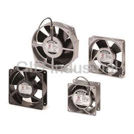
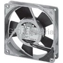
AC Fan Axial Ball Bearing 100V 21.19CFM/24.72CFM 32dB/36dB 80 X 80 X 25mm Long Life/Low Noise
R87F-A1A83H
Part Number
R87F-A1A83H
Price
Request Quote
Manufacturer
OMRON ELECTRONIC COMPONENTS
Lead Time
Request Quote
Category
Thermal Management » Blowers and Fans
Specifications
Manufacturer
Omron Electronic Components
Manufacturers Part #
R87F-A1A83H
Industry Aliases
R87F-A1A83H
Sub-Category
Thermal Management Blowers and Fans
Factory Pack Quantity
40
Datasheet

Extracted Text
AC Axial Fans R87F/R87T CSM_R87F_R87T_DS_E_8_1 Optimum Cooling with a Comprehensive Lineup of Axial Fans • Low noise level, long service life, and resistance to the environment. • Shaft supported by ball bearings for highly-reliable operation. • Plastic-bladed models (44 type) and metal-bladed models (28 type) included in series. • R87T-A@A15H-WR Water-resistant AC Axial Fans (IP X7 degree of protection) added to series. • CE marking compliant and certified by UL and CSA. Note: The compliant standards and certified safety standards depend on the product. Check the information given for available models of Axial fans and the information in Characteristics. For the most recent information on models that have been certified for Be sure to read the Safety Precautions for All safety standards, refer to your OMRON website. Axial Fans. Model Number Structure Model Number Legend R87 - - 12 34567 8 6. Rotational speed 1. Basic series 4. Frame size 0: 150 dia. H: High R87F: Plastic blade 1: 120 × 120 M: Medium R87T: Metal blade 9: 92 × 92 L: Low 8: 80 × 80 2. Rated voltage 7. Terminal type A1: 100 VAC 5. Frame thickness No marking: Lead wires A3: 115 VAC 3: 25 P: Terminals (See note 1.) A4: 200 VAC 5: 38 A6: 230 VAC 8. Type 7: 55 No marking: Standard 3. Frame material WR: Water-resistant A: Die-cast Note: 1. A Plug Cord (R87F-PC) is available as an option for models with terminals. 2. These tables show only how to read product markings. They do not indicate which products are available. Refer to “Ratings and Ordering Information” when ordering. Ordering Information Available Models AC Axial Fans Options (Order Separately) Series Size (mm) Model Datasheet available Product name Model Datasheet available 120 × 120 × t38 R87F-A@A15 Refer to page 2. Plug Cord R87F-PC Refer to page 24. 120 × 120 × t25 R87F-A@A13 Refer to page 4. Finger Guard R87F-FG@ Refer to page 25. R87F (plastic 92 × 92 × t25 R87F-A@A93 Refer to page 6. Filter R87F-FL@(S) Refer to page 26. blades) 80 × 80 × t38 R87F-A@A85 Refer to page 8. Note: Mounting screws are not provided. 80 × 80 × t25 R87F-A@A83 Refer to page 10. 120 × 120 × t38 R87T-A@A15H-WR Refer to page 12. 150-dia. × t55 R87T-A@A07 Refer to page 14. R87T 150-dia. × t38 R87T-A@A05 Refer to page 16. (metal 120 × 120 × t38 R87T-A@A15 Refer to page 18. blades) 80 × 80 × t38 R87T-A@A85 Refer to page 20. 80 × 80 × t25 R87T-A@A83 Refer to page 22. Safety Precautions Refer to the “Safety Precautions for All Axial Fans”. 1 AC Axial Fans with Terminals (120 × 120 × t38 mm) R87F-A@A15 Specifications Ratings and Ordering Information Note: An asterisk (*) indicates a nominal value. Item Rated Maximum Rated Maximum Permitted Rated input rotational static Noise (dB) Rated current flow rate voltage Frequency (W) * speed pressure * voltage 3 (A) * (m /min) * fluctuation (Hz) (r/min) * (Pa) * (V) range (%) Model 50 Hz 60 Hz 50 Hz 60 Hz 50 Hz 60 Hz 50 Hz 60 Hz 50 Hz 60 Hz 50 Hz 60 Hz R87F-A1A15HP 100 0.230 0.220 R87F-A3A15HP 115 0.200 0.180 85% to 110% 50/60 15 14 2,750 3,200 2.7 3.1 93.1 99.0 42 46 rated voltage R87F-A4A15HP 200 0.110 0.100 R87F-A6A15HP 230 0.100 0.085 R87F-A1A15MP 100 0.210 0.180 R87F-A3A15MP 115 0.190 0.160 85% to 110% 50/60 15 14 2,450 2,700 2.2 2.5 63.7 63.7 39 42 rated voltage R87F-A4A15MP 200 0.100 0.090 R87F-A6A15MP 230 0.085 0.075 R87F-A1A15LP 100 0.170 0.150 R87F-A3A15LP 115 0.150 0.130 85% to 110% 50/60 11 10 2,100 2,250 2.0 2.1 44.1 44.1 36 38 rated voltage R87F-A4A15LP 200 0.080 0.070 R87F-A6A15LP 230 0.072 0.064 Characteristics Motor type Single-phase shading coil induction motor (2-pole, open type) Terminal type Terminals IEC class B (130°C) Insulation class UL class A (105°C) CSA class A (105°C) Insulation resistance 100 MΩ min. (at 500 VDC) between all power supply connections and uncharged metal parts. Insulation withstand voltage 2,000 VAC (1 minute) between all power supply connections and uncharged metal parts. Ambient operating temperature −30 to 70°C (no icing) Ambient storage temperature −40 to 85°C (no icing) Ambient humidity 25% to 85% Protection Impedance protection Frame: Die-cast aluminum Materials Blades: Glass polycarbonate Bearings Ball bearings Weight Approx. 540 g Compliant standards PSE, EN/IEC 60335 (CE marking compliant) Certified standards UL/CSA 2 R87F/R87T Flow Rate and Static Pressure Characteristics (Reference Values) R87F-A@A15HP R87F-A@A15MP R87F-A@A15LP 100 100 100 80 80 80 60 Hz 50 Hz 60 60 60 60 Hz 60 Hz 50 Hz 40 40 40 50 Hz 20 20 20 0 0 0.8 1.6 2.4 3.2 0.8 1.6 2.4 3.2 0 0.8 1.6 2.4 3.2 3 3 Flow rate: Q (m /min) Flow rate: Q (m /min) 3 Flow rate: Q (m /min) Note: For details on measurement conditions, refer to Flow Rate and Static Pressure on Safety Precautions for All Axial Fans. Dimensions (Unit: mm) Screw hole for grounding 38±0.5 119.5±0.5 M4 × 0.7 screw 4±0.3 4±0.3 104.8±0.3 11 M4 screw: 0.7 pitch 119.5±0.5 104.8±0.3 Terminal shape 9 Eight, 4.3 dia. 2.8 Direction of rotation Direction of flow Faston #110 terminals (or equivalent) Panel Cutouts Outlet Inlet 104.8±0.3 Four, 4.5 dia. 104.8±0.3 Four, 4.5 dia. 126 dia. 115 dia. 104.8±0.3 104.8±0.3 115 115 Options Name Model Datasheet available Plug Cord R87F-PC Refer to page 24. Finger Guard R87F-FG120 Refer to page 25. Filter R87F-FL120(S) Refer to page 26. ALL DIMENSIONS SHOWN ARE IN MILLIMETERS. To convert millimeters into inches, multiply by 0.03937. To convert grams into ounces, multiply by 0.03527. In the interest of product improvement, specifications are subject to change without notice. 3 Static pressure: Ps (Pa) Static pressure: Ps (Pa) Static pressure: Ps (Pa) Side with label (front) AC Axial Fans with Terminals (120 × 120 × t25 mm) R87F-A@A13 Specifications Ratings and Ordering Information Note: An asterisk (*) indicates a nominal value. Item Rated Maximum Rated Maximum Permitted Rated input rotational static Noise (dB) Rated current flow rate voltage Frequency (W) * speed pressure * voltage 3 (A) * (m /min) * fluctuation (Hz) (r/min) * (Pa) * (V) range (%) Model 50 Hz 60 Hz 50 Hz 60 Hz 50 Hz 60 Hz 50 Hz 60 Hz 50 Hz 60 Hz 50 Hz 60 Hz R87F-A1A13HP 100 0.180 0.150 R87F-A3A13HP 115 0.160 0.130 85% to 110% 50/60 14 12 2,400 2,800 1.9 2.2 44.1 42.2 39 43 rated voltage R87F-A4A13HP 200 0.096 0.078 R87F-A6A13HP 230 0.085 0.068 R87F-A1A13LP 100 0.140 0.110 R87F-A3A13LP 115 0.130 0.100 85% to 110% 50/60 12 10 1,700 2,000 1.3 1.5 19.6 23.5 32 34 rated voltage R87F-A4A13LP 200 0.070 0.055 R87F-A6A13LP 230 0.052 0.045 Characteristics Motor type Single-phase shading coil induction motor (2-pole, open type) Terminal type Terminals IEC class B (130°C) Insulation class UL class A (105°C) CSA class A (105°C) Insulation resistance 100 MΩ min. (at 500 VDC) between all power supply connections and uncharged metal parts. Insulation withstand voltage 2,000 VAC (1 minute) between all power supply connections and uncharged metal parts. Ambient operating temperature –30 to 70°C (no icing) Ambient storage temperature –40 to 85°C (no icing) Ambient humidity 25% to 85% Protection Impedance protection Frame: Die-cast aluminum Materials Blades: Glass polycarbonate Bearings Ball bearings Weight Approx. 350 g Compliant standards PSE, EN/IEC 60335 (CE marking compliant) Certified standards UL/CSA 4 R87F/R87T Flow Rate and Static Pressure Characteristics (Reference Values) R87F-A@A13HP R87F-A@A13LP 50 50 40 40 60 Hz 60 Hz 30 30 50 Hz 50 Hz 20 20 10 10 0 0 0 0.4 0.8 1.2 1.6 2.0 2.4 0 0.4 0.8 1.2 1.6 2.0 2.4 3 3 Flow rate: Q (m /min) Flow rate: Q (m /min) Note: For details on measurement conditions, refer to Flow Rate and Static Pressure on Safety Precautions for All Axial Fans. Dimensions (Unit: mm) 119.5±0.5 104.8±0.3 Eight, 4.3 dia. Screw hole for grounding 9.2 104.8±0.3 M4 screw: 0.7 pitch 119.5±0.5 Terminal shape 2.8 9 4±0.3 4±0.3 Faston #110 terminal 25±0.5 Direction of rotation (or equivalent) Direction of flow Panel Cutouts Outlet Inlet Four, 4.5 dia. Four, 4.5 dia. 104.8±0.3 104.8±0.3 126 dia. 115 dia. 115 104.8±0.3 104.8±0.3 115 Options Name Model Datasheet available Plug Cord R87F-PC Refer to page 24. Finger Guard R87F-FG120 Refer to page 25. Filter R87F-FL120(S) Refer to page 26. ALL DIMENSIONS SHOWN ARE IN MILLIMETERS. To convert millimeters into inches, multiply by 0.03937. To convert grams into ounces, multiply by 0.03527. In the interest of product improvement, specifications are subject to change without notice. 5 Static pressure: Ps (Pa) Static pressure: Ps (Pa) AC Axial Fans with Terminals (92 × 92 × t25 mm) R87F-A@A93 Specifications Ratings and Ordering Information Note: An asterisk (*) indicates a nominal value. Item Rated Maximum Rated Maximum Permitted Rated input rotational static Noise (dB) Rated current flow rate voltage Frequency (W) * speed pressure * voltage 3 (A) * (m /min) * fluctuation (Hz) (r/min) * (Pa) * (V) range (%) Model 50 Hz 60 Hz 50 Hz 60 Hz 50 Hz 60 Hz 50 Hz 60 Hz 50 Hz 60 Hz 50 Hz 60 Hz R87F-A1A93HP 100 0.150 0.130 R87F-A3A93HP 115 0.125 0.100 85% to 110% 50/60 13 11 2,550 3,050 0.9 1.0 49.0 68.6 33 36 rated voltage R87F-A4A93HP 200 0.070 0.060 R87F-A6A93HP 230 0.055 0.050 R87F-A1A93LP 100 0.100 0.085 R87F-A3A93LP 115 0.090 0.075 85% to 110% 50/60 76 1,900 2,200 0.7 0.8 24.5 34.3 29 32 rated voltage R87F-A4A93LP 200 0.050 0.043 R87F-A6A93LP 230 0.045 0.040 Characteristics Motor type Single-phase shading coil induction motor (2-pole, open type) Terminal type Terminals IEC class B (130°C) Insulation class UL class A (105°C) CSA class A (105°C) Insulation resistance 100 MΩ min. (at 500 VDC) between all power supply connections and uncharged metal parts. Insulation withstand voltage 2,000 VAC (1 minute) between all power supply connections and uncharged metal parts. Ambient operating temperature −30 to 70°C (no icing) Ambient storage temperature −40 to 85°C (no icing) Ambient humidity 25% to 85% Protection Impedance protection Frame: Die-cast aluminum Materials Blades: Glass polycarbonate Bearings Ball bearings Weight Approx. 300 g Compliant standards PSE, EN/IEC 60335 (CE marking compliant) Certified standards UL/CSA 6 R87F/R87T Flow Rate and Static Pressure Characteristics (Reference Values) v R87F-A@A93HP R87F-A@A93LP 70 60 Hz 50 60 60 Hz 50 Hz 40 50 50 Hz 30 40 20 30 10 20 0 0 0.2 0.4 0.6 0.8 1.0 10 3 Flow rate: Q (m /min) 0 0 0.2 0.4 0.6 0.8 1.0 3 Flow rate: Q (m /min) Note: For details on measurement conditions, refer to Flow Rate and Static Pressure on Safety Precautions for All Axial Fans. Dimensions (Unit: mm) c Six, 4.3 dia. Screw hole for grounding 7.8 82.5±0.3 92±0.5 M4 screw: 0.7 pitch Two, 3.2±0.15 dia. Terminal shape 2.8 82.5±0.3 4±0.3 4±0.3 92±0.5 9 25±0.5 Faston #110 terminal Direction of rotation (or equivalent) Direction of flow Panel Cutouts Panel cutting reference dimensions (note 3 mounting holes) Outlet Inlet Four, 4.5 dia. Four, 4.5 dia. 82.5±0.3 82.5±0.3 98 dia. 89 dia. 89 82.5±0.3 82.5±0.3 89 Options Name Model Datasheet available Plug Cord R87F-PC Refer to page 24. Finger Guard R87F-FG90 Refer to page 25. Filter R87F-FL90 Refer to page 26. ALL DIMENSIONS SHOWN ARE IN MILLIMETERS. To convert millimeters into inches, multiply by 0.03937. To convert grams into ounces, multiply by 0.03527. In the interest of product improvement, specifications are subject to change without notice. 7 Static pressure: Ps (Pa) Static pressure: Ps (Pa) AC Axial Fans with Terminals (80 × 80 × t38 mm) R87F-A@A85 Specifications Ratings and Ordering Information Note: An asterisk (*) indicates a nominal value. Item Rated Maximum Rated Maximum Permitted Rated input rotational static Noise (dB) Rated current flow rate voltage Frequency (W) * speed pressure * voltage 3 (A) * (m /min) * fluctuation (Hz) (r/min) * (Pa) * (V) range (%) Model 50 Hz 60 Hz 50 Hz 60 Hz 50 Hz 60 Hz 50 Hz 60 Hz 50 Hz 60 Hz 50 Hz 60 Hz R87F-A1A85HP 100 0.140 0.115 R87F-A3A85HP 115 0.120 0.100 85% to 110% 50/60 10 9 2,700 3,200 0.8 0.9 42.1 58.8 32 36 rated voltage R87F-A4A85HP 200 0.080 0.060 R87F-A6A85HP 230 0.060 0.050 R87F-A1A85LP 100 0.090 0.080 R87F-A3A85LP 115 0.080 0.070 85% to 110% 50/60 76 2,200 2,500 0.6 0.7 25.0 32.0 26 29 rated voltage R87F-A4A85LP 200 0.050 0.040 R87F-A6A85LP 230 0.040 0.040 Characteristics Motor type Single-phase shading coil induction motor (2-pole, open type) Terminal type Terminals IEC class B (130°C) Insulation class UL class A (105°C) CSA class A (105°C) Insulation resistance 100 MΩ min. (at 500 VDC) between all power supply connections and uncharged metal parts. Insulation withstand voltage 2,000 VAC (1 minute) between all power supply connections and uncharged metal parts. Ambient operating temperature −30 to 70°C (no icing) Ambient storage temperature −40 to 85°C (no icing) Ambient humidity 25% to 85% Protection Impedance protection Frame: Die-cast aluminum Materials Blades: Glass polycarbonate Bearings Ball bearings Weight Approx. 280 g Compliant standards PSE, EN/IEC 60335 (CE marking compliant) Certified standards UL/CSA 8 R87F/R87T Flow Rate and Static Pressure Characteristics (Reference Values) R87F-A@A85HP R87F-A@A85LP 60 88.3 78.5 50 68.6 60 Hz 40 58.8 50 Hz 49.0 30 39.2 60 Hz 20 29.4 50 Hz 19.6 10 9.8 0 0 0.2 0.4 0.6 0.8 1.0 0 0.25 0.5 0.75 1 3 3 Flow rate: Q (m /min) Flow rate: Q (m /min) Note: For details on measurement conditions, refer to Flow Rate and Static Pressure on Safety Precautions for All Axial Fans. Dimensions (Unit: mm) Eight, 4.3 dia. Screw hole for grounding 5.8 71.5±0.3 M4 screw: 0.7 pitch 80±0.5 Terminal shape 3±0.3 3±0.3 71.5±0.3 80±0.5 8 2.8 38±0.5 Faston #110 terminal (or equivalent) Direction of rotation Direction of flow Panel Cutouts Outlet Inlet Four, 4.5 dia. Four, 4.5 dia. 71.5±0.3 71.5±0.3 90 dia. 77 dia. 77 71.5±0.3 71.5±0.3 77 Options Name Model Datasheet available Plug Cord R87F-PC Refer to page 24. Finger Guard R87F-FG80 Refer to page 25. Filter R87F-FL80 Refer to page 26. ALL DIMENSIONS SHOWN ARE IN MILLIMETERS. To convert millimeters into inches, multiply by 0.03937. To convert grams into ounces, multiply by 0.03527. In the interest of product improvement, specifications are subject to change without notice. 9 Static pressure: Ps (Pa) Static pressure: Ps (Pa) AC Axial Fans with Lead Wires (80 × 80 × t25 mm) R87F-A@A83 Specifications Ratings and Ordering Information Note: An asterisk (*) indicates a nominal value. Item Rated Maximum Rated Maximum Permitted Rated input rotational static Noise (dB) Rated current flow rate voltage Frequency (W) * speed pressure * voltage 3 (A) * (m /min) * fluctuation (Hz) (r/min) * (Pa) * (V) range (%) Model 50 Hz 60 Hz 50 Hz 60 Hz 50 Hz 60 Hz 50 Hz 60 Hz 50 Hz 60 Hz 50 Hz 60 Hz R87F-A1A83H 100 0.097 0.080 R87F-A3A83H 115 0.085 0.070 85% to 110% 50/60 76 2,600 3,000 0.6 0.7 39.2 53.9 32 36 rated voltage R87F-A4A83H 200 0.048 0.041 R87F-A6A83H 230 0.046 0.039 R87F-A1A83L 100 0.063 0.055 R87F-A3A83L 115 0.055 0.048 85% to 110% 50/60 54 1,900 2,100 0.4 0.5 19.5 23.5 28 30 rated voltage R87F-A4A83L 200 0.033 0.030 R87F-A6A83L 230 0.028 0.024 Characteristics Motor type Single-phase shading coil induction motor (2-pole, open type) Terminal type Lead wires IEC class B (130°C) Insulation class UL class A (105°C) CSA class A (105°C) Insulation resistance 100 MΩ min. (at 500 VDC) between all power supply connections and uncharged metal parts. Insulation withstand voltage 2,000 VAC (1 minute) between all power supply connections and uncharged metal parts. Ambient operating temperature −30 to 70°C (no icing) Ambient storage temperature −40 to 85°C (no icing) Ambient humidity 25% to 85% Protection Impedance protection Frame: Die-cast aluminum Materials Blades: Glass polycarbonate Bearings Ball bearings Weight Approx. 230 g Compliant standards EN/IEC 60335 (CE marking compliant) Certified standards UL/CSA 10 R87F/R87T Flow Rate and Static Pressure Characteristics (Reference Values) R87F-A@A83H R87F-A@A83L 60 40 60 Hz 60 Hz 50 30 50 Hz 50 Hz 40 20 30 10 20 0 0 0.2 0.4 0.6 3 Flow rate: Q (m /min) 10 0 0 0.2 0.4 0.6 3 Flow rate: Q (m /min) Note: For details on measurement conditions, refer to Flow Rate and Static Pressure on Safety Precautions for All Axial Fans. Dimensions (Unit: mm) 300 0.3 sq Eight, 4.3 dia. Screw hole for grounding 71.5±0.3 M4 screw: 0.7 pitch 80±0.5 6 3±0.3 3±0.3 71.5±0.3 80±0.5 25±0.5 Direction of rotation Direction of flow Panel Cutouts Outlet Inlet Four, 4.5 dia. Four, 4.5 dia. 71.5±0.3 71.5±0.3 90 dia. 77 dia. 77 71.5±0.3 71.5±0.3 77 Options Names Model Datasheet available Finger Guard R87F-FG80 Refer to page 25. Filter R87F-FL80 Refer to page 26. ALL DIMENSIONS SHOWN ARE IN MILLIMETERS. To convert millimeters into inches, multiply by 0.03937. To convert grams into ounces, multiply by 0.03527. In the interest of product improvement, specifications are subject to change without notice. 11 Static pressure: Ps (Pa) Static pressure: Ps (Pa) Water-resistant AC Axial Fans with Lead Wires (120 × 120 × t38 mm) R87T-A@A15H-WR Specifications Ratings and Ordering Information Note: An asterisk (*) indicates a nominal value. Item Rated Maximum Rated Maximum Permitted Rated input rotational static Noise (dB) Rated current flow rate voltage Frequency (W) * speed pressure * voltage 3 (A) * (m /min) * fluctuation (Hz) (r/min) * (Pa) * (V) range (%) Model 50 Hz 60 Hz 50 Hz 60 Hz 50 Hz 60 Hz 50 Hz 60 Hz 50 Hz 60 Hz 50 Hz 60 Hz R87T-A1A15H-WR 100 0.350 0.280 R87T-A3A15H-WR 115 0.300 0.240 22 20 85% to 110% 50/60 2,550 2,900 2.7 3.2 75.0 80.0 42 46 rated voltage R87T-A4A15H-WR 200 0.170 0.135 R87T-A6A15H-WR 200 to 230 0.145 0.115 15 to 22 Characteristics Motor type Single-phase shading coil induction motor (2-pole, open type) Terminal type Lead wires IEC class B (130°C) Insulation class UL class A (105°C) CSA class A (105°C) Insulation resistance 100 MΩ min. (at 500VDC) between all power supply connections and uncharged metal parts. Insulation withstand voltage 2,000 VAC (1 minute) between all power supply connections and uncharged metal parts. Degree of protection IP X7 Ambient operating temperature −40 to 70°C (no icing) Ambient storage temperature −40 to 85°C (no icing) Ambient humidity 95% max. Protection Impedance protection Die-cast aluminum Frame Black coating Materials Blades Zinc die-cast Bearings Ball bearings Weight Approx. 650 g Standards EN/IEC 60335 (CE marking compliant) Certified standards CUL 12 R87F/R87T Flow Rate and Static Pressure Characteristics (Reference Values) R87T-A@A15H-WR 80 60 Hz 60 50 Hz 40 20 0 0 1.0 2.0 3.0 3 Flow rate Q (m /min) Note: For details on measurement conditions, refer to Flow Rate and Static Pressure on Safety Precautions for All Axial Fans. Dimensions (Unit: mm) 119.5±0.5 38±0.5 104.8±0.3 4±0.3 4±0.3 Lead wire groove (coated with sealant) Ground Screw Section 119.5±0.5 11 300 M4 screw: 0.7 pitch 104.8±0.3 UL1333 AWG22 Eight, 4.3 dia. M4 × 0.7 Direction of flow Direction of rotation double sems screw Panel Cutouts Outlet Inlet Four, 4.5 dia. Four, 4.5 dia. 104.8±0.3 104.8±0.3 126 dia. 115 dia. 115 104.8±0.3 104.8±0.3 115 Options Name Model Page number Finger Guard R87F-FG120 Refer to page 25. Filter R87F-FL120(S) Refer to page 26. ALL DIMENSIONS SHOWN ARE IN MILLIMETERS. To convert millimeters into inches, multiply by 0.03937. To convert grams into ounces, multiply by 0.03527. In the interest of product improvement, specifications are subject to change without notice. 13 Static pressure Ps (Pa) AC Axial Fans with Lead Wires (150-dia. × t55 mm) R87T-A@A07 Specifications Ratings and Ordering Information Note: An asterisk (*) indicates a nominal value. Item Rated Maximum Rated Maximum Permitted Rated input rotational static Noise (dB) Rated current flow rate voltage Frequency (W) * speed pressure * voltage 3 (A) * (m /min) * fluctuation (Hz) (r/min) * (Pa) * (V) range (%) Model 50 Hz 60 Hz 50 Hz 60 Hz 50 Hz 60 Hz 50 Hz 60 Hz 50 Hz 60 Hz 50 Hz 60 Hz R87T-A1A07H 100 0.480 0.420 R87T-A3A07H 115 0.420 0.370 85% to 110% 50/60 43 40 2,800 3,250 5.0 5.8 118 88 52 56 rated voltage R87T-A4A07H 200 0.240 0.210 R87T-A6A07H 230 0.210 0.190 Characteristics Motor type Single-phase shading coil induction motor (2-pole, open type) Terminal type Lead wires IEC class B (130°C) Insulation class UL class A (105°C) Insulation resistance 100 MΩ min. (at 500 VDC) between all power supply connections and uncharged metal parts. Insulation withstand voltage 2,000 VAC (1 minute) between all power supply connections and uncharged metal parts. Ambient operating temperature −20 to 70°C (no icing) Ambient storage temperature −40 to 85°C (no icing) Ambient humidity 25% to 85% Protection Thermal protection Frame: Die-cast aluminum Materials Blades: Steel plate (black coating) Bearings Ball bearings Weight Approx. 1,200 g Compliant standards EN/IEC 60335 (CE marking compliant) Certified standards UL 14 R87F/R87T Flow Rate and Static Pressure Characteristics (Reference Value) R87T-A@A07H 140 120 50 Hz 100 60 Hz 80 60 40 20 0 0 12 3 4 56 7 3 Flow rate: Q (m /min) Note: For details on measurement conditions, refer to Flow Rate and Static Pressure on Safety Precautions for All Axial Fans. Dimensions (Unit: mm) 150±0.5 dia. 55±0.5 Four, 4.3 dia. 6±0.3 6±0.3 162±0.3 175±1.5 146 dia. 144 dia. Ground Screw Section 300 0.5 sq 7 Direction of flow Direction of rotation Panel Cutouts Outlet and Inlet 146 dia. 162±0.3 Two, 4.5 dia. Options Name Model Datasheet available Finger Guard R87F-FG150 Refer to page 25. ALL DIMENSIONS SHOWN ARE IN MILLIMETERS. To convert millimeters into inches, multiply by 0.03937. To convert grams into ounces, multiply by 0.03527. In the interest of product improvement, specifications are subject to change without notice. 15 Static pressure: Ps (Pa) AC Axial Fans with Lead Wires (150-dia. × t38 mm) R87T-A@A05 Specifications Ratings and Ordering Information Note: An asterisk (*) indicates a nominal value. Item Rated Maximum Rated Maximum Permitted Rated input rotational static Noise (dB) Rated current flow rate voltage Frequency (W) * speed pressure * voltage 3 (A) * (m /min) * fluctuation (Hz) (r/min) * (Pa) * (V) range (%) Model 50 Hz 60 Hz 50 Hz 60 Hz 50 Hz 60 Hz 50 Hz 60 Hz 50 Hz 60 Hz 50 Hz 60 Hz R87T-A1A05H 100 0.550 0.460 R87T-A3A05H 115 0.470 0.390 85% to 110% 50/60 50 48 2,650 3,100 4.8 5.7 104 107 56 58 rated voltage R87T-A4A05H 200 0.260 0.220 R87T-A6A05H 230 0.220 0.190 Characteristics Motor type Single-phase shading coil induction motor (2-pole, open type) Terminal type Lead wires IEC class B (130°C) Insulation class UL class A (105°C) Insulation resistance 100 MΩ min. (at 500 VDC) between all power supply connections and uncharged metal parts. Insulation withstand voltage 2,000 VAC (1 minute) between all power supply connections and uncharged metal parts. Ambient operating temperature −20 to 70°C (no icing) Ambient storage temperature −40 to 85°C (no icing) Ambient humidity 25% to 85% Protection Thermal protection Frame: Die-cast aluminum Materials Blades: Steel plate (mat black baked coating) Bearings Ball bearings Weight Approx. 840 g Compliant standards EN/IEC 60335 (CE marking compliant) Certified standards UL 16 R87F/R87T Flow Rate and Static Pressure Characteristics (Reference Value) R87T-A@A05H 120 100 50 Hz 80 60 Hz 60 40 20 0 0 1.0 2.0 3.0 4.0 5.0 6.0 3 Flow rate: Q (m /min) Note: For details on measurement conditions, refer to Flow Rate and Static Pressure on Safety Precautions for All Axial Fans. Dimensions (Unit: mm) 38±0.5 151 dia. Four, 4.3 dia. 6±0.3 6±0.3 146 dia. 144 dia. 175±1.5 162±0.3 Ground Screw Section 300 7 0.5 sq Direction of flow Direction of rotation Panel Cutouts Outlet and Inlet 146 dia. 162±0.3 Two, 4.5 dia. Options Name Model Datasheet available Finger Guard R87F-FG150 Refer to page 25. ALL DIMENSIONS SHOWN ARE IN MILLIMETERS. To convert millimeters into inches, multiply by 0.03937. To convert grams into ounces, multiply by 0.03527. In the interest of product improvement, specifications are subject to change without notice. 17 Static pressure: Ps (Pa) AC Axial Fans with Terminals (120 × 120 × t38 mm) R87T-A@A15 Specifications Ratings and Ordering Information Note: An asterisk (*) indicates a nominal value. Item Rated Maximum Rated Maximum Permitted Rated input rotational static Noise (dB) Rated current flow rate voltage Frequency (W) * speed pressure * voltage 3 (A) * (m /min) * fluctuation (Hz) (r/min) * (Pa) * (V) range (%) Model 50 Hz 60 Hz 50 Hz 60 Hz 50 Hz 60 Hz 50 Hz 60 Hz 50 Hz 60 Hz 50 Hz 60 Hz R87T-A1A15HP 100 0.250 0.210 R87T-A3A15HP 115 0.215 0.190 85% to 110% 50/60 20 18 2,700 3,100 2.6 3.0 66.6 58.8 42 46 rated voltage R87T-A4A15HP 200 0.130 0.110 R87T-A6A15HP 230 0.105 0.095 R87T-A1A15MP 100 0.220 0.190 R87T-A3A15MP 115 0.200 0.170 85% to 110% 50/60 16 14 2,350 2,750 1.7 2.0 36.7 37.3 36 40 rated voltage R87T-A4A15MP 200 0.110 0.100 R87T-A6A15MP 230 0.100 0.085 Characteristics Motor type Single-phase shading coil induction motor (2-pole, open type) Terminal type Terminals IEC class B (130°C) Insulation class UL class A (105°C) Insulation resistance 100 MΩ min. (at 500 VDC) between all power supply connections and uncharged metal parts. Insulation withstand voltage 2,000 VAC (1 minute) between all power supply connections and uncharged metal parts. Ambient operating temperature −20 to 70°C (no icing) Ambient storage temperature −40 to 85°C (no icing) Ambient humidity 25% to 85% Protection Impedance protection Frame: Die-cast aluminum Materials Blades: Steel plate (black coating) Bearings Ball bearings Weight Approx. 570 g Compliant standards PSE, EN/IEC 60335 (CE marking compliant) Certified standards UL 18 R87F/R87T Flow Rate and Static Pressure Characteristics (Reference Values) v R87T-A@A15HP R87T-A@A15MP 70 70 60 60 60Hz 50 50 60 Hz 50Hz 40 40 50 Hz 30 30 20 20 10 10 0 0 0 1.0 2.0 3.0 0 1.0 2.0 3.0 3 3 Flow rate: Q (m /min) Flow rate: Q (m /min) Note: For details on measurement conditions, refer to Flow Rate and Static Pressure on Safety Precautions for All Axial Fans. Dimensions (Unit: mm) Screw hole for grounding Eight, 4.3 dia. 11 104.8±0.3 119.5±0.5 M4 screw: 0.7 pitch Terminal shape 104.8±0.3 6±0.3 6±0.3 9 2.8 119.5±0.5 38±0.5 Faston #110 terminal (or equivalent) Direction of rotation Direction of flow Panel Cutouts Outlet Inlet 104.8±0.3 Four, 4.5 dia. 104.8±0.3 Four, 4.5 dia. 126 dia. 114 dia. 114 104.8±0.3 104.8±0.3 114 Options Name Model Datasheet available Plug Cord R87F-PC Refer to page 24. Finger Guard R87F-FG120 Refer to page 25. Filter R87F-FL120(S) Refer to page 26. ALL DIMENSIONS SHOWN ARE IN MILLIMETERS. To convert millimeters into inches, multiply by 0.03937. To convert grams into ounces, multiply by 0.03527. In the interest of product improvement, specifications are subject to change without notice. 19 Static pressure: Ps (Pa) Static pressure: Ps (Pa) AC Axial Fans with Lead Wires (80 × 80 × t38 mm) R87T-A@A85 Specifications Ratings and Ordering Information Note: An asterisk (*) indicates a nominal value. Item Rated Maximum Rated Maximum Permitted Rated input rotational static Noise (dB) Rated current flow rate voltage Frequency (W) * speed pressure * voltage 3 (A) * (m /min) * fluctuation (Hz) (r/min) * (Pa) * (V) range (%) Model 50 Hz 60 Hz 50 Hz 60 Hz 50 Hz 60 Hz 50 Hz 60 Hz 50 Hz 60 Hz 50 Hz 60 Hz R87T-A1A85H 100 0.180 0.160 R87T-A3A85H 115 0.155 0.135 85% to 110% 50/60 12 10 2,800 3,300 0.80 0.90 42 58 37 40 rated voltage R87T-A4A85H 200 0.085 0.075 R87T-A6A85H 230 0.080 0.070 Characteristics Motor type Single-phase shading coil induction motor (2-pole, open type) Terminal type Lead wires IEC class B (130°C) Insulation class UL class A (105°C) Insulation resistance 100 MΩ min. (at 500 VDC) between all power supply connections and uncharged metal parts. Insulation withstand voltage 2,000 VAC (1 minute) between all power supply connections and uncharged metal parts. Ambient operating temperature −20 to 70°C (no icing) Ambient storage temperature −40 to 85°C (no icing) Ambient humidity 25% to 85% Protection Impedance protection Frame: Die-cast aluminum Materials Blades: Steel plate (black coating) Bearings Ball bearings Weight Approx. 440 g Compliant standards EN/IEC 60335 (CE marking compliant) Certified standards UL 20 5.8 R87F/R87T Flow Rate and Static Pressure Characteristics (Reference Values) R87T-A@A85H 60 50 40 60 Hz 30 50 Hz 20 10 0 0 0.2 0.4 0.6 0.8 1.0 3 Flow rate: Q (m /min) Note: For details on measurement conditions, refer to Flow Rate and Static Pressure on Safety Precautions for All Axial Fans. Dimensions (Unit: mm) 300 0.3 sq Eight, 4.5 dia. Screw hole for grounding 80±0.5 M4 screw: 0.7 pitch 71.5±0.3 71.5±0.3 3±0.3 3±0.3 80±0.5 38±0.5 Direction of rotation Direction of flow Panel Cutouts Outlet Inlet Four, 4.5 dia. Four, 4.5 dia. 71.5±0.3 71.5±0.3 90 dia. 77 dia. 77 71.5±0.3 71.5±0.3 77 Options Name Model Datasheet available Finger Guard R87F-FG80 Refer to page 25. Filter R87F-FL80 Refer to page 26. ALL DIMENSIONS SHOWN ARE IN MILLIMETERS. To convert millimeters into inches, multiply by 0.03937. To convert grams into ounces, multiply by 0.03527. In the interest of product improvement, specifications are subject to change without notice. 21 Static pressure: Ps (Pa) AC Axial Fans with Lead Wires (80 × 80 × t25 mm) R87T-A@A83 Specifications Ratings and Ordering Information Note: An asterisk (*) indicates a nominal value. Item Rated Maximum Rated Maximum Permitted Rated input rotational static Rated current flow rate Noise (dB)* voltage Frequency (W)* speed pressure voltage 3 (A)* (m /min)* fluctuation (Hz) (r/min)* (Pa)* (V) range (%) Model 50 Hz 60 Hz 50 Hz 60 Hz 50 Hz 60 Hz 50 Hz 60 Hz 50 Hz 60 Hz 50 Hz 60 Hz R87T-A1A83H 100 0.180 0.150 R87T-A3A83H 115 0.150 0.130 85% to 110% 50/60 12 11 2,500 3,000 0.5 0.6 34.0 49.0 33 36 rated voltage R87T-A4A83H 200 0.087 0.075 R87T-A6A83H 230 0.075 0.065 Characteristics Motor type Single-phase shading coil induction motor (2-pole, open type) Terminal type Lead wires IEC class B (130°C) Insulation class UL class A (105°C) Insulation resistance 100 MΩ min. (at 500VDC) between all power supply connections and uncharged metal parts. Insulation withstand voltage 2,000 VAC (1 minute) between all power supply connections and uncharged metal parts. Ambient operating temperature −20 to 70°C (no icing) Ambient storage temperature −40 to 85°C (no icing) Ambient humidity 25% to 85% Protection Impedance protection Frame Die-cast aluminum Materials Blades Steel plate (black coating) Bearings Ball bearings Weight Approx. 330 g Standards EN/IEC 60335 (CE marking compliant) Certified standards UL 22 R87F/R87T Flow Rate and Static Pressure Characteristics (Reference Values) R87T-A@A83H 50 60 Hz 40 50 Hz 30 20 10 0 0 0.2 0.4 0.6 3 Flow rate: Q (m /min) Note: For details on measurement conditions, refer to Flow Rate and Static Pressure on Safety Precautions for All Axial Fans. Dimensions (Unit: mm) 26.5 max. 300 0.3 sq Eight, 4.5 dia. Screw hole for grounding 5.5 80±0.5 71.5±0.3 M4 screw: 0.7 pitch 71.5±0.3 3±0.3 3±0.3 80±0.5 25±0.5 Direction of rotation Direction of flow Panel Cutouts Outlet Inlet Four, 4.5 dia. Four, 4.5 dia. 71.5±0.3 71.5±0.3 90 dia. 77 dia. 77 71.5±0.3 71.5±0.3 77 Options Name Model Datasheet available Finger Guard R87F-FG80 Refer to page 25. Filter R87F-FL80 Refer to page 26. ALL DIMENSIONS SHOWN ARE IN MILLIMETERS. To convert millimeters into inches, multiply by 0.03937. To convert grams into ounces, multiply by 0.03527. In the interest of product improvement, specifications are subject to change without notice. 23 Static pressure: Ps (Pa) Plug Cord R87F-PC Accessories (Order Separately) Available Models Cord length Model number Weight (g) 1 m R87F-PC 39 2 m R87F-PC-20 69 R87F-PC Rating: 250 VAC, 3 A UL-certified Plug Cord Dimensions (Unit: mm) R87F-PC 9±0.5 7.5±0.5 ±0.5 23.5 1,000 ±0.5 (8) 15.5 ±0.5 18 Connectable to Faston #110 terminals (or equivalent). Note: This Plug Cord is used for Axial Fans with terminals. ALL DIMENSIONS SHOWN ARE IN MILLIMETERS. To convert millimeters into inches, multiply by 0.03937. To convert grams into ounces, multiply by 0.03527. In the interest of product improvement, specifications are subject to change without notice. 24 Finger Guards R87F-FG Accessories (Order Separately) Available Models Applicable Axial Fans Size Model number Weight (g) AC Axial Fan Finger Guard 150 dia. R87F-FG150 Approx. 58 Size Model 120 × 120 R87F-FG120 Approx. 45 150 dia. R87T-A@A0 Series R87F-FG150 92 × 92 R87F-FG90 Approx. 25 R87F-A@A1 Series 120 × 120 R87F-FG120 R87T-A@A1 Series 80 × 80 R87F-FG80 Approx. 20 92 × 92 R87F-A@A9 Series R87F-FG90 R87F-A@A8 Series 80 × 80 R87F-FG80 R87T-A@A8 Series Note: Finger Guards reduce the flow rate by approximately 2% to 5%. Dimensions (Unit: mm) Material: steel, Joints: spot welded, Surface: nickel-chrome plated R87F-FG150 R87F-FG120 6 Four, 4.6±0.3 dia. 5.5 105±0.5 22 dia. 27 dia. 105±0.5 5.6 162.6 6 R87F-FG90 R87F-FG80 +0.2 Four, 4.6 dia. Four, 4.6 dia. 0 82.4 71.5 82.4 71.5 5 5.5 ALL DIMENSIONS SHOWN ARE IN MILLIMETERS. To convert millimeters into inches, multiply by 0.03937. To convert grams into ounces, multiply by 0.03527. In the interest of product improvement, specifications are subject to change without notice. 25 Filters R87F-FL Accessories (Order Separately) Available Models Applicable Axial Fans AC Axial Fan Filter Filter Size Model Plastic Aluminum Size Model number Weight (g) 150 dia. R87T-A@A0 Series --- --- 120 × 120 R87F-FL120 Approx. 43 R87F-A@A1 Series 120 × 120 R87F-FL120 R87F-FL120S 92 × 92 R87F-FL90 Approx. 30 R87T-A@A1 Series 80 × 80 R87F-FL80 Approx. 21 92 × 92 R87F-A@A9 Series R87F-FL90 --- 120 × 120 R87F-FL120S Approx. 19 R87F-A@A8 Series 80 × 80 R87F-FL80 --- R87T-A@A8 Series Note: The filter contains one medium. Note: Filters reduce the flow rate by approximately 20% to 40%. Media Ensure that there is no clogging. Size Model number 120 × 120 R87F-FL120-M120 92 × 92 R87F-FL90-M90 80 × 80 R87F-FL80-M80 Note: Use the following model number to order the Media only. R87F-FL@-M@ (@: 120, 90, or 80) (One set containing five Media, weight: 5 g max.) Dimensions (Unit: mm) R87F-FL@ Plastic Filter R87F-FL120 10.5 118 123.7 6.3 104.8 118 123.7 104.8 Guard Media Plastic filter Four, 4.5-dia. 93.5 R87F-FL90 82.5 96.5 10.5 Retainer Mounting Method 1. Attach the guard to the Fan using the 93.5 96.5 mounting bolts. (There are no mounting 82.5 bolts provided with the Plastic Filter.) 2. With the media held between the retainer and the guard, hook the retainer to the guard. (The Media and retainer can be Four, 3.8 dia. one-touch mounted/dismounted.) 80 10 R87F-FL80 83.5 71.3 5.8 R87F-FL120S Screen Filter 80 83.5 71.3 Four, 4.5-dia. R87F-FL120S 4 119.5±0.5 Note: 1. The Screen Filter is Four, 2 104.8±0.3 4.3 dia. made using aluminium and has an EMI/RFI shielding effect. 2. When mounting the Screen filter 119.5±0.5 Screen Filter, make sure 104.8±0.3 that it does not come in contact with the fan Stainless steel blades. screen 3. The screen is a 30 × 30 aluminum mesh. (30 aluminum wires per inch) Aluminum frame 26 R87F/R87T ALL DIMENSIONS SHOWN ARE IN MILLIMETERS. To convert millimeters into inches, multiply by 0.03937. To convert grams into ounces, multiply by 0.03527. In the interest of product improvement, specifications are subject to change without notice. 27 Terms and Conditions Agreement Read and understand this catalog. Please read and understand this catalog before purchasing the products. Please consult your OMRON representative if you have any questions or comments. Warranties. (a) Exclusive Warranty. Omron’s exclusive warranty is that the Products will be free from defects in materials and workmanship for a period of twelve months from the date of sale by Omron (or such other period expressed in writing by Omron). Omron disclaims all other warranties, express or implied. (b) Limitations. OMRON MAKES NO WARRANTY OR REPRESENTATION, EXPRESS OR IMPLIED, ABOUT NON-INFRINGEMENT, MERCHANTABILITY OR FITNESS FOR A PARTICULAR PURPOSE OF THE PRODUCTS. BUYER ACKNOWLEDGES THAT IT ALONE HAS DETERMINED THAT THE PRODUCTS WILL SUITABLY MEET THE REQUIREMENTS OF THEIR INTENDED USE. Omron further disclaims all warranties and responsibility of any type for claims or expenses based on infringement by the Products or otherwise of any intellectual property right. (c) Buyer Remedy. Omron’s sole obligation hereunder shall be, at Omron’s election, to (i) replace (in the form originally shipped with Buyer responsible for labor charges for removal or replacement thereof) the non-complying Product, (ii) repair the non-complying Product, or (iii) repay or credit Buyer an amount equal to the purchase price of the non-complying Product; provided that in no event shall Omron be responsible for warranty, repair, indemnity or any other claims or expenses regarding the Products unless Omron’s analysis confirms that the Products were properly handled, stored, installed and maintained and not subject to contamination, abuse, misuse or inappropriate modification. Return of any Products by Buyer must be approved in writing by Omron before shipment. Omron Companies shall not be liable for the suitability or unsuitability or the results from the use of Products in combination with any electrical or electronic components, circuits, system assemblies or any other materials or substances or environments. Any advice, recommendations or information given orally or in writing, are not to be construed as an amendment or addition to the above warranty. See http://www.omron.com/global/ or contact your Omron representative for published information. Limitation on Liability; Etc. OMRON COMPANIES SHALL NOT BE LIABLE FOR SPECIAL, INDIRECT, INCIDENTAL, OR CONSEQUENTIAL DAMAGES, LOSS OF PROFITS OR PRODUCTION OR COMMERCIAL LOSS IN ANY WAY CONNECTED WITH THE PRODUCTS, WHETHER SUCH CLAIM IS BASED IN CONTRACT, WARRANTY, NEGLIGENCE OR STRICT LIABILITY. Further, in no event shall liability of Omron Companies exceed the individual price of the Product on which liability is asserted. Suitability of Use. Omron Companies shall not be responsible for conformity with any standards, codes or regulations which apply to the combination of the Product in the Buyer’s application or use of the Product. At Buyer’s request, Omron will provide applicable third party certification documents identifying ratings and limitations of use which apply to the Product. This information by itself is not sufficient for a complete determination of the suitability of the Product in combination with the end product, machine, system, or other application or use. Buyer shall be solely responsible for determining appropriateness of the particular Product with respect to Buyer’s application, product or system. Buyer shall take application responsibility in all cases. NEVER USE THE PRODUCT FOR AN APPLICATION INVOLVING SERIOUS RISK TO LIFE OR PROPERTY OR IN LARGE QUANTITIES WITHOUT ENSURING THAT THE SYSTEM AS A WHOLE HAS BEEN DESIGNED TO ADDRESS THE RISKS, AND THAT THE OMRON PRODUCT(S) IS PROPERLY RATED AND INSTALLED FOR THE INTENDED USE WITHIN THE OVERALL EQUIPMENT OR SYSTEM. Programmable Products. Omron Companies shall not be responsible for the user’s programming of a programmable Product, or any consequence thereof. Performance Data. Data presented in Omron Company websites, catalogs and other materials is provided as a guide for the user in determining suitability and does not constitute a warranty. It may represent the result of Omron’s test conditions, and the user must correlate it to actual application requirements. Actual performance is subject to the Omron’s Warranty and Limitations of Liability. Change in Specifications. Product specifications and accessories may be changed at any time based on improvements and other reasons. It is our practice to change part numbers when published ratings or features are changed, or when significant construction changes are made. However, some specifications of the Product may be changed without any notice. When in doubt, special part numbers may be assigned to fix or establish key specifications for your application. Please consult with your Omron’s representative at any time to confirm actual specifications of purchased Product. Errors and Omissions. Information presented by Omron Companies has been checked and is believed to be accurate; however, no responsibility is assumed for clerical, typographical or proofreading errors or omissions. 2017.1 In the interest of product improvement, specifications are subject to change without notice. OMRON Corporation Industrial Automation Company http://www.ia.omron.com/ (c)Copyright OMRON Corporation 2017 All Right Reserved.
Frequently asked questions
How does Electronics Finder differ from its competitors?

Is there a warranty for the R87F-A1A83H?
Which carrier will Electronics Finder use to ship my parts?
Can I buy parts from Electronics Finder if I am outside the USA?
Which payment methods does Electronics Finder accept?
Why buy from GID?

Quality
We are industry veterans who take pride in our work

Protection
Avoid the dangers of risky trading in the gray market

Access
Our network of suppliers is ready and at your disposal

Savings
Maintain legacy systems to prevent costly downtime

Speed
Time is of the essence, and we are respectful of yours
Related Products
AC Fan Axial Ball Bearing 115V 45.9CFM/52.97CFM 49dB/52dB 180 X 180 X 64.5mm R87B-FA3A15HPF
AC Fan Axial Ball Bearing 115V 45.91CFM/52.97CFM 49dB/52dB 180 X 180 X 64.5mm R87B-FA3A15HPFR
AC Fan Axial Ball Bearing 200V 91.81CFM/105.94CFM 55dB/56dB 180 X 180 X 64.5mm R87B-FA4A15HPFR2
AC Fan Axial Ball Bearing 100V 67.1CFM/77.69CFM 39dB/43dB 119.5 X 119.5 X 25mm Long Life/Low Noise R...
AC Fan Axial Ball Bearing 100V 45.91CFM/52.97CFM 32dB/34dB 119.5 X 119.5 X 25mm Long Life/Low Noise ...
AC Fan Axial Ball Bearing 100V 95.35CFM/109.48CFM 42dB/46dB 119.5 X 119.5 X 38mm Long Life/Low Noise...
Request a Quote

The quote request has been received
Close

Facing challenges or have inquiries? Feel free to contact us!
Call Us +1-469-283-2440
What they say about us
FANTASTIC RESOURCE
One of our top priorities is maintaining our business with precision, and we are constantly looking for affiliates that can help us achieve our goal. With the aid of GID Industrial, our obsolete product management has never been more efficient. They have been a great resource to our company, and have quickly become a go-to supplier on our list!
Bucher Emhart Glass
EXCELLENT SERVICE
With our strict fundamentals and high expectations, we were surprised when we came across GID Industrial and their competitive pricing. When we approached them with our issue, they were incredibly confident in being able to provide us with a seamless solution at the best price for us. GID Industrial quickly understood our needs and provided us with excellent service, as well as fully tested product to ensure what we received would be the right fit for our company.
Fuji
HARD TO FIND A BETTER PROVIDER
Our company provides services to aid in the manufacture of technological products, such as semiconductors and flat panel displays, and often searching for distributors of obsolete product we require can waste time and money. Finding GID Industrial proved to be a great asset to our company, with cost effective solutions and superior knowledge on all of their materials, it’d be hard to find a better provider of obsolete or hard to find products.
Applied Materials
CONSISTENTLY DELIVERS QUALITY SOLUTIONS
Over the years, the equipment used in our company becomes discontinued, but they’re still of great use to us and our customers. Once these products are no longer available through the manufacturer, finding a reliable, quick supplier is a necessity, and luckily for us, GID Industrial has provided the most trustworthy, quality solutions to our obsolete component needs.
Nidec Vamco
TERRIFIC RESOURCE
This company has been a terrific help to us (I work for Trican Well Service) in sourcing the Micron Ram Memory we needed for our Siemens computers. Great service! And great pricing! I know when the product is shipping and when it will arrive, all the way through the ordering process.
Trican Well Service
GO TO SOURCE
When I can't find an obsolete part, I first call GID and they'll come up with my parts every time. Great customer service and follow up as well. Scott emails me from time to time to touch base and see if we're having trouble finding something.....which is often with our 25 yr old equipment.
ConAgra Foods