

 Manufacturers
OMRON ELECTRONIC COMPONENTS XF2B-2545-31A
Description
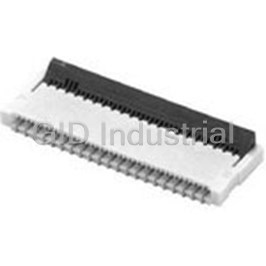
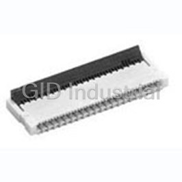
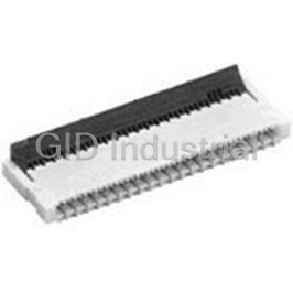
Conn FPC Connector SKT 25 POS 0.3mm Solder RA SMD Reel
XF2B-2545-31A
Part Number
XF2B-2545-31A
Price
Request Quote
Manufacturer
OMRON ELECTRONIC COMPONENTS
Lead Time
Request Quote
Category
Connectors » Connector FFC-FPC
Specifications
Manufacturer
Omron Electronic Components
Manufacturers Part #
XF2B-2545-31A
Lead Time
8 Week Lead Time
Industry Aliases
XF2B-2545-31A
Sub-Category
FFC & FPC Connectors
Packaging
Reel
Factory Pack Quantity
1500
Datasheet

Extracted Text
FPC/FFC Connectors XF Series XF3E XF3H XF3A XF3B XF3C XF2L XF2U XF2W XF2B XF2J XF2M See How Far FPC Connectors Have Advanced * Use this legend when determining the product specifications from the model number. Model Number Legend Product Overview Choose from the model numbers listed in this catalog when ordering. Applicable FPC/ Model Lock mechanism Pitch On-board height Depth (*4) Contact type Page FFC thickness XF--- FOR FPC Rotary backlock 0.25mm 0.85mm 3.8mm 0.12mm Dual contact P6 (1) (2) (3) (4) (5) (6) (7) (8) XF3C 3: One-row, single-sided contact (1) Classification in Series (5) Applicable FPC thickness (7) Plating FOR FPC (lower contact) 1: 0.3mm Upper contact 2B, 2J, 2L, 2M, 2U, 2W, A: Au Rotary backlock 0.3mm 0.6mm 3.8mm 0.12mm P7 XF3A 4: Two-row, double-sided contact 3: 0.2mm 3A, 3B, 3C, 3E, 3H (8) Special Correspondence FOR FPC 4: 0.12mm 5: Two-row, single-sided contact R100: 100pcs Rotary backlock 0.3mm 0.9mm 4.0mm *3 0.2mm (2) Number of Signal Contact Pins Dual contact P8 5: 0.15mm *Only XF2M, XF2W XF3B (4) Terminal Shape (3) Signal Contact Arrangement (6) Terminal Arrangement FOR FPC E: Easy lock type 4: SMT terminals Dual contact : Standard Rotary backlock 0.3mm 1.1mm 4.3mm 0.2mm P9 1: One-row, double-sided contact H: For multiple pins (top entry) XF3E 1: Staggered arrangement 2: One-row, single-sided contact 5: SMT terminals FOR FPC (forward arrangement) (including upper contact Rotary backlock 0.3mm 1.2mm 5.5mm 0.2mm Dual contact *1 (side entry) P10 2: Staggered arrangement and top entry) XF2B (backward arrangement) FOR FPC Rotary frontlock 0.3mm 0.9mm 3.5mm 0.2mm Lower contact P11 XF3H FOR FPC Rotary backlock 0.5mm 0.9mm 3.5mm 0.2mm Dual contact P12 Applications XF2U FOR FPC/FFC Dual contact Rotary backlock 0.5mm 1.1mm 3.5mm *3 0.3mm P13 XF2W FOR FPC/FFC Rotary backlock 0.5mm 2.0mm *2 5.9mm *2 0.3mm Dual contact P14 XF2M FOR FPC Upper/lower Slide lock 0.5mm 1.2mm 3.45mm 0.3mm P15 contact XF2L FOR FPC Mobile phones Digital cameras Digital music players Single-sided Slide lock 0.5mm 4.15mm *5 3.45mm 0.3mm P16 contact XF2J *1: Models with 61 pins have upper contacts. *2: Dimensions of multiple type is different. *3: 4.1 mm for more than 45 pins. *4: These are latch closed dimension. *5: 4.25 mm for 40 pins. Storage Device Digital video cameras LCD-TV, PDP-TV Ultra sound Electricity meter Surveillance camera 2 3 See How Far FPC Connectors Have Advanced * Use this legend when determining the product specifications from the model number. Model Number Legend Product Overview Choose from the model numbers listed in this catalog when ordering. Applicable FPC/ Model Lock mechanism Pitch On-board height Depth (*4) Contact type Page FFC thickness XF--- FOR FPC Rotary backlock 0.25mm 0.85mm 3.8mm 0.12mm Dual contact P6 (1) (2) (3) (4) (5) (6) (7) (8) XF3C 3: One-row, single-sided contact (1) Classification in Series (5) Applicable FPC thickness (7) Plating FOR FPC (lower contact) 1: 0.3mm Upper contact 2B, 2J, 2L, 2M, 2U, 2W, A: Au Rotary backlock 0.3mm 0.6mm 3.8mm 0.12mm P7 XF3A 4: Two-row, double-sided contact 3: 0.2mm 3A, 3B, 3C, 3E, 3H (8) Special Correspondence FOR FPC 4: 0.12mm 5: Two-row, single-sided contact R100: 100pcs Rotary backlock 0.3mm 0.9mm 4.0mm *3 0.2mm (2) Number of Signal Contact Pins Dual contact P8 5: 0.15mm *Only XF2M, XF2W XF3B (4) Terminal Shape (3) Signal Contact Arrangement (6) Terminal Arrangement FOR FPC E: Easy lock type 4: SMT terminals Dual contact : Standard Rotary backlock 0.3mm 1.1mm 4.3mm 0.2mm P9 1: One-row, double-sided contact H: For multiple pins (top entry) XF3E 1: Staggered arrangement 2: One-row, single-sided contact 5: SMT terminals FOR FPC (forward arrangement) (including upper contact Rotary backlock 0.3mm 1.2mm 5.5mm 0.2mm Dual contact *1 (side entry) P10 2: Staggered arrangement and top entry) XF2B (backward arrangement) FOR FPC Rotary frontlock 0.3mm 0.9mm 3.5mm 0.2mm Lower contact P11 XF3H FOR FPC Rotary backlock 0.5mm 0.9mm 3.5mm 0.2mm Dual contact P12 Applications XF2U FOR FPC/FFC Dual contact Rotary backlock 0.5mm 1.1mm 3.5mm *3 0.3mm P13 XF2W FOR FPC/FFC Rotary backlock 0.5mm 2.0mm *2 5.9mm *2 0.3mm Dual contact P14 XF2M FOR FPC Upper/lower Slide lock 0.5mm 1.2mm 3.45mm 0.3mm P15 contact XF2L FOR FPC Mobile phones Digital cameras Digital music players Single-sided Slide lock 0.5mm 4.15mm *5 3.45mm 0.3mm P16 contact XF2J *1: Models with 61 pins have upper contacts. *2: Dimensions of multiple type is different. *3: 4.1 mm for more than 45 pins. *4: These are latch closed dimension. *5: 4.25 mm for 40 pins. Storage Device Digital video cameras LCD-TV, PDP-TV Ultra sound Electricity meter Surveillance camera 2 3 See How Far FPC Connectors See How Far FPC Connectors Have Advanced Have Advanced Features of Rotary Backlock Mechanism Introduction of Product OMRON delivers cutting-edge innovative products a step ahead of customer needs. Please look forward to the continuing development of our new products. Feature 1 Feature 2 XF3A Ultra-slim FPC Connectors Rotary latch independent of the FPC socket Four-sided housing Ultra-low profile with an on-board height of 0.6mm. Rotary latch does not disconnect if the Construction prevents FPC displacement. ZIF structure with 0.6mm on-board height FPC is lifted. Mounting reliability is enhanced because the FPC is held in a Ultra-low construction supports LCR downsizing. four-sided housing and is unaffected by the slider operation. The rotary back lock ensures operability. High reliability – A mounted FPC will not come off if Halogen free. excess force is applied to it. 0.12mmZIF 0.6mm Contribute to Downsizing of Mobile Devices Possible to downsize compare with existing connectors. Rotary Slider Connector Specifications Pitch 0.3mm Example: Mounted on Height 0.6mm a key switch PCB Tradition Rotary Connector XF2 Series Depth 3.8mm FPC Socket 1. Mount the connector. 1. Mount the connector. FPC thickness 0.12mm Contact orientation Upper contact Upper Contact Lock mechanism Rotary backlock Lower Contact 2. Release the rotary latch. 2. Insert the FPC. XF3C 0.25mm Pitch FPC Connector 0.25mm pitch Dual contact type Dual contact connector with 0.25mm pitch Contributing to miniature mobile Devices. Dual contact reduces the number of parts. 3. Lock the rotary slider. 3. Insert the FPC. The rotary backlock ensures operability. Upper contact Upper Contact Halogen free. Lower contact Lower Contact Single sided FPC with an applicable thickness of 0.12mm 4. Lock the rotary latch. 0.25mm Feature 3 Feature 4 Connector Specifications Decreased 20% of mounting area, compared with our Pitch 0.25mm Dual contact Delivered with the rotary latch open. 0.3mm pitch connector Height 0.85mm * Except the XF3A series and XF2B-61 pin. Depth 3.8mm Reduces the operation. No need to discriminate between the FPC thickness 0.12mm upper and lower FPC connection. Compared with traditional rotary lock connector, it is no need It’s no necessary to distinguish between the upper and lower Contact orientation Dual contact for latch unlock operation that improves your operation. Compare with 0.3 mm pitch contacts when connecting upper and lower PCBs. Lock mechanism Rotary backlock connector size 4 5 See How Far FPC Connectors See How Far FPC Connectors Have Advanced Have Advanced Features of Rotary Backlock Mechanism Introduction of Product OMRON delivers cutting-edge innovative products a step ahead of customer needs. Please look forward to the continuing development of our new products. Feature 1 Feature 2 XF3A Ultra-slim FPC Connectors Rotary latch independent of the FPC socket Four-sided housing Ultra-low profile with an on-board height of 0.6mm. Rotary latch does not disconnect if the Construction prevents FPC displacement. ZIF structure with 0.6mm on-board height FPC is lifted. Mounting reliability is enhanced because the FPC is held in a Ultra-low construction supports LCR downsizing. four-sided housing and is unaffected by the slider operation. The rotary back lock ensures operability. High reliability – A mounted FPC will not come off if Halogen free. excess force is applied to it. 0.12mmZIF 0.6mm Contribute to Downsizing of Mobile Devices Possible to downsize compare with existing connectors. Rotary Slider Connector Specifications Pitch 0.3mm Example: Mounted on Height 0.6mm a key switch PCB Tradition Rotary Connector XF2 Series Depth 3.8mm FPC Socket 1. Mount the connector. 1. Mount the connector. FPC thickness 0.12mm Contact orientation Upper contact Upper Contact Lock mechanism Rotary backlock Lower Contact 2. Release the rotary latch. 2. Insert the FPC. XF3C 0.25mm Pitch FPC Connector 0.25mm pitch Dual contact type Dual contact connector with 0.25mm pitch Contributing to miniature mobile Devices. Dual contact reduces the number of parts. 3. Lock the rotary slider. 3. Insert the FPC. The rotary backlock ensures operability. Upper contact Upper Contact Halogen free. Lower contact Lower Contact Single sided FPC with an applicable thickness of 0.12mm 4. Lock the rotary latch. 0.25mm Feature 3 Feature 4 Connector Specifications Decreased 20% of mounting area, compared with our Pitch 0.25mm Dual contact Delivered with the rotary latch open. 0.3mm pitch connector Height 0.85mm * Except the XF3A series and XF2B-61 pin. Depth 3.8mm Reduces the operation. No need to discriminate between the FPC thickness 0.12mm upper and lower FPC connection. Compared with traditional rotary lock connector, it is no need It’s no necessary to distinguish between the upper and lower Contact orientation Dual contact for latch unlock operation that improves your operation. Compare with 0.3 mm pitch contacts when connecting upper and lower PCBs. Lock mechanism Rotary backlock connector size 4 5 For FPC XF3C Rotary Backlock Connector (0.25-mm Pitch, Dual Contact) 0.25 mm Pitch with Dual contact and Rotary Backlock Mechanism Wide molding wall on the rear bottom of the connector allows greater freedom in board design. Dual contact. Single sided FPC with an applicable thickness of 0.12 mm. (*) Halogen Free * OMRON uses the following standard to determine halogen-free construction: 900 ppm max. for Br, 900 ppm max. for Cl, and 1,500 ppm max. for Br+Cl. RoHS compliant ■ Ratings and Specifications ■ Materials and Finish Rated current 0.2 A AC/DC Housing LCP resin (UL94V-0)/natural Rated voltage 50 V AC/DC Slider LCP resin (UL94V-0)/black Contact resistance 80 m max. (at 20 mV DC max., 100 mA max.) Spring copper alloy/nickel substrate (2 m) Contacts Gold-plated contacts (0.15 m) Insulation resistance 100 M min. (at 250 V DC) Dielectric strength 250 V AC for 1 min. (leakage current: 1 mA max.) Insertion durability 20 times Ambient operating temperature 30 to 85 C (With no icing or condensation) ■ Dimensions XF3C-@@45-41A PCB Dimensions (TOP VIEW) ± 0.05 A (1.25) ± 0.05 A 0.5 ± 0.05 0.25 0.25 ± 0.05 0.5 0.1 0.25 3.8 Contact No.2 (2.1) 0.65 ± 0.05 Contact No.1 (1.6) ± 0.05 2.75 (4) 3.2 (0.2) 0.6 ± 0.05 0.35 0.4 0.1 3.6 0.5 ± 0.05 ± 0.05 0.25 0.5 ± 0.05 0.1 B 1.6 Pin number (1) B 1 (Effective stacking length) indication C 0.45 (Effective stacking length) Applicable FPC Dimensions ± 0.03 A 0.5 ± 0.02 X ± 0.02 Reference pin mark 0.05 (0.1) (0.1) + 0.04 0.25 – 0.03 Cross-section diagram: X-X 1 (Effective 0.85 stacking length) (0.3) X 0.45 (Effective stacking length) D 0.65 ± 0.1 2.8 Table of Dimensions (Reinforcement board) ± 0.3 ± 0.1 ± 0.1 1.8 1.4 1.3 * 1 Pins Model A BCD ± 0.1 0.75 17 XF3C-1745-41A 3.5 4.0 6.0 4.55 ± 0.1 0.15 2-R0.2 MAX. + 0.04 19 XF3C-1945-41A 4.0 4.5 6.5 5.05 0.25 – 0.03 0.25 ± 0.02 23 XF3C-2345-41A 5.0 5.5 7.5 6.05 ± 0.02 0.5 25 XF3C-2545-41A 5.5 6.0 8.0 6.55 ± 0.03 ± 0.07 ± 0.03 0.12 (0.25 ) B 0.25 ± 0.07 ± 0.05 (B + 0.5) 35 XF3C-3545-41A 8.0 8.5 10.5 9.05 45 XF3C-4545-41A 10.5 11.0 13.0 11.55 51 XF3C-5145-41A 12.0 12.5 14.5 13.05 59 XF3C-5945-41A 14.0 14.5 16.5 15.05 ■ Ordering Information * 1 * 2 Pins Model Quantity per reel (unit) *1. Please consult your OMRON representative for; · Available pin count 17 XF3C-1745-41A · Release date of pin count with bracket 19 XF3C-1945-41A *2. Please order by integer multiple of the quantity per reel. 23 XF3C-2345-41A 25 XF3C-2545-41A 2,000 35 XF3C-3545-41A 45 XF3C-4545-41A 51 XF3C-5145-41A 59 XF3C-5945-41A 6 XF3C For FPC XF3A Rotary Backlock Connector (0.3-mm Pitch, Upper Contact) On-board height 0.6 mm, the lowest class profile in the industry. Rotary Backlock Connectors with a 0.3-mm pitch. Wide molding wall on the rear bottom of the connector allows greater freedom in board design. Upper Contact Halogen Free (* ) * OMRON uses the following standard to determine halogen-free construction: 900 ppm max. for Br, 900 ppm max. for Cl, and 1,500 ppm max. for Br+Cl. RoHS compliant ■ Ratings and Specifications ■ Materials and Finish Rated current 0.2 A AC/DC Housing LCP resin (UL94V-0)/natural Rated voltage 50 V AC/DC Slider LCP resin (UL94V-0)/black Contact resistance 80 m max. (at 20 mV DC max., 100 mA max.) Spring copper alloy/nickel substrate (2 m) Contacts Gold-plated contacts (0.15 m) Insulation resistance 100 M min. (at 250 V DC) Dielectric strength 250 V AC for 1 min. (leakage current: 1 mA max.) Insertion durability 10 times Ambient operating temperature 30 to 85 C (With no icing or condensation) ■ Dimensions XF3A-@@55-41A PCB Dimensions (TOP VIEW) A (0.12) A F D ± 0.03 0.60 ± 0.03 0.30 ± 0.03 0.30 ± 0.02 0.75 ± 0.03 3.80 2.15 ± 0.03 (0.12) 3.10 Cross-section diagram: X-X (1.7) F 0.75± 0.03 1 (Effective stacking length) 0.45 (Effective stacking length) 0.30 ± 0.02 (0.10) C ± 0.03 1.65 Pin number indication (0.45) (0.45) Reference pin mark Applicable FPC Dimensions FPC insertion dimension 3.40 B E ± 0.05 Unlocked 0.30 ± 0.07 C ± 0.03 D ± 0.03 C 0.15 ± 0.1 0.60 ± 0.02 D 0.65 ± 0.1 0.60 0.30 ± 0.02 0.12 ± 0.03 0.75 ± 0.1 3.80 R0.20 max. 0.30 ± 0.03 1.40 ± 0.1 1 (Effective stacking length) 1.50 2 min. Locked min. (Reinforcement 0.45 board) 0.10 ± 0.03 0.30 0.60 0.10 ± 0.03 Table of Dimensions 0.30 ± 0.03 0.20 ± 0.03 * 1 * 3 Pins Model A B C DE F 8 XF3A-0855-41A 3.8 2.75 2.1 1.8 2.7 3.1 12 XF3A-1255-41A 5.0 3.95 3.3 3.0 3.9 4.3 17 XF3A-1755-41A 6.5 5.45 4.8 4.2 5.4 5.8 23 XF3A-2355-41A 8.3 7.25 6.6 6.0 7.2 7.6 25 XF3A-2555-41A 8.9 7.85 7.2 6.6 7.8 8.2 51 XF3A-5155-41A 16.7 15.65 15.0 14.4 15.6 16.0 ■ Ordering Information * 1 * 2 Pins Model Quantity per reel (unit) *1. Please consult your OMRON representative for available pin count. 8 XF3A-0855-41A *2. Please order by integer multiple of the quantity per reel. 12 XF3A-1255-41A *3. Dimension C indicates total pitch. 17 XF3A-1755-41A 4,000 23 XF3A-2355-41A 25 XF3A-2555-41A 51 XF3A-5155-41A 7 (1.56) 0.60 XF3A For FPC XF3B Rotary Backlock Connector (0.3-mm Pitch, Dual Contact) Compact body (with a low profile of just 0.9 mm) supports the applicable FPC thickness of 0.2 mm. Wide molding wall on the rear bottom of the connector allows greater freedom in board design. Dual contact model to enhance the contact structure of lower contact. Gold plated with an applicable FPC thickness of 0.2 mm. Halogen Free (* ) * OMRON uses the following standard to determine halogen-free construction: 900 ppm max. for Br, 900 ppm max. for Cl, and 1,500 ppm max. for Br+Cl. RoHS compliant ■ Ratings and Specifications ■ Materials and Finish Rated current 0.2 A AC/DC Housing LCP resin (UL94V-0)/natural Rated voltage 50 V AC/DC Slider LCP resin (UL94V-0)/brown Contact resistance 80 m max. (at 20 mV DC max., 100 mA max.) Spring copper alloy/nickel substrate (2 m) Contacts Gold-plated contacts (0.15 m) Insulation resistance 100 M min. (at 250 V DC) Dielectric strength 250 V AC for 1 min. (leakage current: 1 mA max.) Insertion durability 20 times Ambient operating temperature 30 to 85 C (With no icing or condensation) ■ Dimensions XF3B-@@45-31A XF3B-@@45-31AE PCB Dimensions (TOP VIEW) ± 0.05 (1.4) A A 0.6 ± 0.05 0.3 0.12 0.6 0.3 ± 0.05 ± 0.05 0.65 0.3 ± 0.05 Cross-section diagram: X-X (4.2) 1.8 ± 0.05 2.95 1.1 (Effective stacking length) (0.2) 3.4 0.55 (Effective stacking length) 0.6 ± 0.05 0.1 ± 0.05 0.6 ± 0.05 0.3 ± 0.05 B 0.12 0.6 B Applicable FPC Dimensions (1.1) ± 0.03 C Locked A + 0.04 4.5 0.6 ± 0.02 0.1 ± 0.02 0.3 – 0.03 * 4 (0.2) * 1.1 (2.3) (0.2) X (Effective stacking (2.3) length) ± 0.1 1.4 (2.1) 0.55 (1.6) 0.85 ± 0.1 (Effective 0.9 ± 0.1 0.75 stacking length) ± 0.1 * 0.25 3 X 0.35 (Reinforcement 0.4 ± 0.3 D 2 board) 1.45 ± 0.1 3.8 FPC insertion dimension + 0.04 ± 0.02 0.2 ± 0.03 0.3 0.3 * Dotted lines indicate the shape and dimensions – 0.03 2-R0.2 MAX Table of Dimensions 0.6 ± 0.02 of the XF3B-@@45-31AE connectors. ± 0.07 ± 0.03 ± 0.07 (0.3) B 0.3 * 2 * 1 * 4 Pins Model AB CD (B + 0.6) ± 0.05 8 XF3B-0845-31A 1.8 2.1 4.3 2.75 T = 0.2 ± 0.03 19 XF3B-1945-31A 4.8 5.4 7.6 6.05 (Conductive plating) 25 XF3B-2545-31A 6.6 7.2 9.4 7.85 35 XF3B-3545-31A 9.6 10.2 12.4 10.85 51 XF3B-5145-31AE 14.4 15.0 17.2 15.65 67 XF3B-6745-31AE 19.2 19.8 22.0 20.45 ■ Ordering Information * 2 * 1 * 3 Pins Model Quantity per reel (unit) *1. The end of the model number indicates the slider specification. None: Standard type E: Easy lock type 8 XF3B-0845-31A 2,000 *2. Please consult your OMRON representative for available pin count. 19 XF3B-1945-31A 2,000 *3. Please order by integer multiple of the quantity per reel. 25 XF3B-2545-31A 2,000 *4. Dimension B indicates total pitch. 35 XF3B-3545-31A 2,000 51 XF3B-5145-31AE 1,500 67 XF3B-6745-31AE 1,500 8 XF3B XF3E Rotary Backlock Connector (0.3-mm Pitch, Dual Contact) Large number of contacts with 0.3-mm Pitch and 1.1-mm On-board Height Rotary Backlock Connector. Dual contact. Gold plated with an applicable FPC thickness of 0.2 mm. Halogen Free (* ) * OMRON uses the following standard to determine halogen-free construction: 900 ppm max. for Br, 900 ppm max. for Cl, and 1,500 ppm max. for Br+Cl. RoHS compliant ■ Ratings and Specifications ■ Materials and Finish Rated current 0.2 A AC/DC Housing LCP resin (UL94V-0)/natural Rated voltage 50 V AC/DC Slider LCP resin (UL94V-0)/black Contact resistance 80 m max. (at 20 mV DC max., 100 mA max.) Spring copper alloy/nickel substrate (2 m) Contacts Gold-plated contacts (0.15 m) Insulation resistance 100 M min. (at 250 V DC) Dielectric strength 250 V AC for 1 min. (leakage current: 1 mA max.) Insertion durability 20 times Ambient operating temperature 30 to 85 C (With no icing or condensation) ■ Dimensions XF3E-@@45-31AE PCB Dimensions (TOP VIEW) C D ± 0.03 ± 0.03 (1.4) B 0.3 B 0.3 0.6 0.6 ± 0.03 Contact Contact No.2 No.2 ± 0.03 0.12 0.3 ± 0.03 0.65 Cross-section diagram :X-X Lot No. 1.65 (FPC insertion depth) 1.1 (Effective stacking length) (0.2) 0.55 (Effective stacking length) 0.5 MIN. 3.4 4.3 Pattern Prohibited area (4.2) Pin 3.4 2.95 ± 0.03 number indication (0.2) Contact 0.12 0.6 No.1 (1.1) A ± 0.03 0.3 ± 0.03 0.6 Contact No.1 C ± 0.03 0.6 4.3 ± 0.03 A Reference (With slider locked.) D pin mark X (2.1) Applicable FPC Dimensions ± 0.05 (A + 0.6) ±0.07 ± 0.03 ±0.07 (0.3 ) A 0.3 (2.1) + 0.04 2-R0.2 MAX 0.6 ± 0.02 1.1 (1.1) 0.3 – 0.03 1.45 ± 0.1 ± 0.02 (0.2) ± 0.1 0.3 1.4 ± 0.03 0.75 ± 0.1 0.2 ± 0.1 0.1 ± 0.02 ± 0.1 0.85 0.25 X 0.35 0.4 E 3.8 0.75 ± 0.1 ± 0.1 0.85 (FPC insertion dimension) 2 ± 0.3 ± 0.1 0.15 0.55 3.5 ± 0.5 (Effective stacking length) 1.1 (Effective stacking length) Table of Dimensions * 1 Pins Model A B C D E ± 0.02 0.1 (0.2) 90 XF3E-9045-31AE 26.7 26.4 28.9 27.9 27.4 + 0.04 0.3 – 0.03 ■ Ordering Information *1. Please consult your OMRON representative for available pin count. * 1 * 2 Pins Model Quantity per reel (unit) *2. Please order by integer multiple of the quantity per reel. 90 XF3E-9045-31AE 1,500 9 XF3E For FPC XF2B Rotary Backlock Connector (0.3-mm Pitch, Dual Contact) Rotary Backlock Mechanism with 0.3-mm Pitch Wide molding wall on the rear bottom of the connector allows greater freedom in board design. Dual contact reduces the number of parts. Gold plated with an applicable FPC thickness of 0.2 mm. Halogen Free (* ) * OMRON uses the following standard to determine halogen-free construction: 900 ppm max. for Br, 900 ppm max. for Cl, and 1,500 ppm max. for Br+Cl. RoHS compliant ■ Ratings and Specifications ■ Materials and Finish Rated current 0.2 A AC/DC Housing LCP resin (UL94V-0)/natural Rated voltage 50 V AC/DC Slider LCP resin (UL94V-0)/black Contact resistance 50 m max. (at 20 mV DC max., 100 mA max.) Spring copper alloy/nickel substrate (2 m) Contacts Gold-plated contacts (0.15 m) Insulation resistance 100 M min. (at 250 V DC) Dielectric strength 250 V AC for 1 min. (leakage current: 1 mA max.) Insertion durability 20 times Ambient operating temperature 30 to 85 C (With no icing or condensation) ■ Dimensions XF2B-@@@5-31A (1.4) A PCB Dimensions (TOP VIEW) 0.3 0.6 0.15 ± 0.05 A ± 0.05 0.6 ± 0.05 0.3 ± 0.05 0.75 Cross-section diagram: X-X ± 0.1 5.4 ± 0.05 0.3 2.15 1.6 (Effective stacking length) ± 0.05 0.75 0.8 (Effective stacking length) ± 0.05 0.3 ± 0.05 0.6 B ± 0.05 0.12 0.6 (1.1) B D Applicable FPC Dimensions 0.5 X ± 0.03 A +0.04 ± 0.02 0.3 0.6 -0.03 (2.1) 1.2 4.5 (Reinforcement board) X 0.1 0.5 1.2 ± 0.1 Table of Dimensions C 1.23 0.55 2.5 ± 0.3 5.2 1.6 * 1 ± 0.1 2 Pins Model A B C D ± 0.1 (Effective stacking length) 5.5 1 17 XF2B-1745-31A 4.2 4.8 5.5 7.0 21 XF2B-2145-31A 5.4 6.0 6.7 8.2 ± 0.1 0.8 (Effective stacking length) 0.25 ± 0.02 0.3 23 XF2B-2345-31A 6.0 6.6 7.3 8.8 +0.04 ± 0.07 0.6 ± 0.02 0.3 0.3 -0.03 25 XF2B-2545-31A 6.6 7.2 7.9 9.4 ± 0.03 B 2-R0.2 MAX ± 0.05 27 XF2B-2745-31A 7.2 7.8 8.5 10.0 (B + 0.6) T = 0.2 ± 0.03 31 XF2B-3145-31A 8.4 9.0 9.7 11.2 (Conductive plating) 33 XF2B-3345-31A 9.0 9.6 10.3 11.8 35 XF2B-3545-31A 9.6 10.2 10.9 12.4 39 XF2B-3945-31A 10.8 11.4 12.1 13.6 41 XF2B-4145-31A 11.4 12.0 12.7 14.2 45 XF2B-4545-31A 12.6 13.2 13.9 15.4 51 XF2B-5145-31A 14.4 15.0 15.7 17.2 61 XF2B-6155-31A 17.4 18.0 18.7 20.2 ■ Ordering Information * 1 * 1 * 2 Pins Model Pins Model Quantity per reel (unit) *1. Please consult your OMRON representative for available pin count. 17 XF2B-1745-31A 35 XF2B-3545-31A *2. Please order by integer multiple of the 21 XF2B-2145-31A 39 XF2B-3945-31A quantity per reel. 23 XF2B-2345-31A 41 XF2B-4145-31A *3. Upper contact. 25 XF2B-2545-31A 45 XF2B-4545-31A 1,500 27 XF2B-2745-31A 51 XF2B-5145-31A 3 31 XF2B-3145-31A 61 XF2B-6155-31A* 33 XF2B-3345-31A - - 10 XF2B For FPC XF3H Rotary Frontlock Connector (0.3-mm Pitch, Lower Contact) Rotary Frontlock Mechanism with a Depth of 3.5-mm and Low Profile of 0.9 mm Ultra-slim connector with a depth of 3.5 mm. Wide molding wall on the rear bottom of the connector allows greater freedom in board design. Slider open locking mechanism makes work efficient. Gold plated with an applicable FPC thickness of 0.2 mm. Halogen Free (* ) * OMRON uses the following standard to determine halogen-free construction: 900 ppm max. for Br, 900 ppm max. for Cl, and 1,500 ppm max. for Br+Cl. RoHS compliant ■ Ratings and Specifications ■ Materials and Finish Rated current 0.2 A AC/DC Housing LCP resin (UL94V-0)/natural Rated voltage 50 V AC/DC Slider LCP resin (UL94V-0)/brown Contact resistance 80 m max. (at 20 mV DC max., 100 mA max.) Spring copper alloy/nickel substrate (2 m) Contacts Gold-plated contacts (0.15 m) Insulation resistance 100 M min. (at 250 V DC) Dielectric strength 250 V AC for 1 min. (leakage current: 1 mA max.) Insertion durability 20 times Ambient operating temperature 30 to 85 C (With no icing or condensation) ■ Dimensions XF3H-@@55-31A PCB Dimensions (TOP VIEW) Side with even number of contacts B ± 0.05 Housing C ± 0.05 (0.2) 0.3 0.65 ± 0.05 1.1 (0.45) ± 0.05 2.15 (3.6) A 13 Locked ± 0.05 0.8 2.1 Pin number indication Reference pin mark Slider 1.5 ± 0.05 (0.2) 0.8 (Effective stacking 0.3 D (Effective stacking length) ± 0.05 FPC insertion dimension A length) 0.9 Applicable FPC Dimensions 0.3 0.5 E ± 0.05 A 0.25 2.8 Side with odd number of contacts ± 0.03 ± 0.07 A 0.3 0.6 0.12 3.2 0.3 B ± 0.03 0.6 ± 0.07 ± 0.02 0.6 Unlocked R0.2 MAX. 0.3 ± 0.02 ± 0.03 0.2 + 0.04 ± 0.1 ± 0.1 0.3 1.1 0.3 0.5 – 0.03 (125 °) Soldering (2) Soldering 0.8 dimension dimension (Effective stacking length) ± 0.1 1 1.5 ± 0.1 2.1 0.3 (Effective stacking length) 2.25 ± 0.1 3 MIN. 2.5 ± 0.3 (Supporting film) 0.12 0.3 B Table of Dimensions (0.2) * 1 Pins Model A B C D E 13 XF3H-1355-31A 3.63.05.4 4.234.2 25 XF3H-2555-31A 7.26.69.0 7.837.8 (0.05) 0.1 ± 0.02 31 XF3H-3155-31A 9.08.4 10.8 9.639.6 (0.15) + 0.04 (0.2) 0.3 35 XF3H-3555-31A 10.2 9.6 12.0 10.83 10.8 – 0.03 39 XF3H-3955-31A 11.4 10.8 13.2 12.03 12.0 41 XF3H-4155-31A 12.0 11.4 13.8 12.63 12.6 45 XF3H-4555-31A 13.2 12.6 15.0 13.83 13.8 51 XF3H-5155-31A 15.0 14.4 16.8 15.63 15.6 57 XF3H-5755-31A 16.8 16.2 18.6 17.43 17.4 61 XF3H-6155-31A 18.0 17.4 19.8 18.63 18.6 ■ Ordering Information * 1 * 1 * 2 Pins Model Pins Model Quantity per reel (unit) *1. Please consult your OMRON representative for available pin count. 13 XF3H-1355-31A 41 XF3H-4155-31A *2. Please order by integer multiple of the 25 XF3H-2555-31A 45 XF3H-4555-31A quantity per reel. 31 XF3H-3155-31A 51 XF3H-5155-31A 3,000 35 XF3H-3555-31A 57 XF3H-5755-31A 39 XF3H-3955-31A 61 XF3H-6155-31A 11 XF3H For FPC XF2U Rotary Backlock Connector (0.5-mm Pitch, Dual Contact) Rotary Backlock Mechanism with a Depth of 3.5-mm and Low Profile of 0.9 mm Ultra-slim connector with a depth of 3.5 mm. Dual contact reduces the number of parts. Wide molding wall on the rear bottom of the connector allows greater freedom in board design. Gold plated with an applicable FPC thickness of 0.2 mm. Halogen Free (* ) * OMRON uses the following standard to determine halogen-free construction: 900 ppm max. for Br, 900 ppm max. for Cl, and 1,500 ppm max. for Br+Cl. RoHS compliant ■ Ratings and Specifications ■ Materials and Finish Rated current 0.5 A AC/DC Housing LCP resin (UL94V-0)/natural Rated voltage 50 V AC/DC Slider LCP resin (UL94V-0)/black Contact resistance 60 m max. (at 20 mV DC max., 100 mA max.) Spring copper alloy/nickel substrate (2 m) Contacts Gold-plated contacts (0.15 m) Insulation resistance 100 M min. (at 250 V DC) Hold-down Spring copper alloy/fused-tin plating (2 m) Dielectric strength 250 V AC for 1 min. (leakage current: 1 mA max.) Insertion durability 20 times Ambient operating temperature 30 to 85 C (With no icing or condensation) ■ Dimensions XF2U-@@15-3A Applicable FPC Dimensions A PCB Dimensions (TOP VIEW) 0.5 ± 0.08 ± 0.05 (D-0.1) Contacts 0.12 E A ± 0.03 ± 0.05 ± 0.07 A 0.5 ± 0.05 0.5 Pin number 0.5 ± 0.03 Pattern Prohibited area 0.2 ± 0.03 ± 0.05 0.3 ± 0.03 indication 0.35 2-R 0.2 0.8 (Effective Housing stacking length) ± 0.05 1.5 MIN. 0.8 2.5 MIN. (0.15) 1.5 MIN. 3.3 ± 0.05 (3.4) 0.15 (0.15) ± 0.05 0.8 B C Reference pin mark 3.4 X F ± 0.1 (2) (0.125) G ± 0.1 Slider 1.2 (1.4) Table of Dimensions 0.9 * 1 Pins Model ABC D E F G X 0.5 4 XF2U-0415-3A 1.5 3.5 4.0 2.6 1.8 3.1 3.9 D 0.8 Hold-down FPC insertion dimension (Effective stacking length) 6 XF2U-0615-3A 2.5 4.5 5.0 3.6 2.8 4.1 4.9 Hold-down soldering Cross-section diagram: X-X 8 XF2U-0815-3A 3.5 5.5 6.0 4.6 3.8 5.1 5.9 dimension 11 XF2U-1115-3A 5.0 7.0 7.5 6.1 5.3 6.6 7.4 Unlocked 14 XF2U-1415-3A 6.5 8.5 9.0 7.6 6.8 8.1 8.9 3.5 18 XF2U-1815-3A 8.5 10.5 11.0 9.6 8.8 10.1 10.9 (0.1) 20 XF2U-2015-3A 9.5 11.5 12.0 10.6 9.8 11.1 11.9 (3) 24 XF2U-2415-3A 11.5 13.5 14.0 12.6 11.8 13.1 13.9 0.9 27 XF2U-2715-3A 13.0 15.0 15.5 14.1 13.3 14.6 15.4 30 XF2U-3015-3A 14.5 16.5 17.0 15.6 14.8 16.1 16.9 Locked 32 XF2U-3215-3A 15.5 17.5 18.0 16.6 15.8 17.1 17.9 0.4 40 XF2U-4015-3A 19.5 21.5 22.0 20.6 19.8 21.1 21.9 Contacts soldering dimension ■ Ordering Information * 1 * 2 Pins Model Quantity per reel (unit) *1. Please consult your OMRON representative for available pin count. *2. Please order by integer multiple of the quantity per reel. 4 XF2U-0415-3A 6 XF2U-0615-3A 8 XF2U-0815-3A 11 XF2U-1115-3A 14 XF2U-1415-3A 18 XF2U-1815-3A 3,000 20 XF2U-2015-3A 24 XF2U-2415-3A 27 XF2U-2715-3A 30 XF2U-3015-3A 32 XF2U-3215-3A 40 XF2U-4015-3A 12 XF2U For FPC/FFC XF2W Rotary Backlock Connector (0.5-mm Pitch, Dual Contact) Rotary Backlock Mechanism with 0.5-mm Pitch and Low Profile of 1.1 mm Two models available: Low profile connector with a depth of 3.5 mm and easy-operation connector with long slider. Dual contact reduces the number of parts. Wide molding wall on the rear bottom of the connector allows greater freedom in board design. Gold plated with an applicable FPC/FFC thickness of 0.3 mm. (*) Halogen Free * OMRON uses the following standard to determine halogen-free construction: 900 ppm max. for Br, 900 ppm max. for Cl, and 1,500 ppm max. for Br+Cl. RoHS compliant ■ Ratings and Specifications ■ Materials and Finish Rated current 0.5 A AC/DC Housing LCP resin (UL94V-0)/natural Rated voltage 50 V AC/DC Slider LCP resin (UL94V-0)/brown Contact resistance 60 m max. (at 20 mV DC max., 100 mA max.) Spring copper alloy/nickel substrate (2 m) Contacts Gold-plated contacts (0.15 m) Insulation resistance 100 M min. (at 250 V DC) Hold-down Spring copper alloy/fused-tin plating (2 m) Dielectric strength 250 V AC for 1 min. (leakage current: 1 mA max.) Insertion durability 20 times Ambient operating temperature 30 to 85 C (With no icing or condensation) ■ Dimensions XF2W-@@15-1A Applicable FPC/FFC Dimensions PCB Dimensions (TOP VIEW) A H ± 0.05 ± 0.05 E XF2W-@@15-1AE 0.5 Contacts ± 0.07 ± 0.03 ± 0.05 0.5 A A 0.12 0.5 ± 0.03 ± 0.05 Pattern Prohibited area 0.5 ± 0.03 0.35 (FPC) 2-R0.2 0.8 ± 0.05 0.3 ± 0.05 ± 0.03 ± 0.05 0.30 (FFC) 0.3 Pin number indication 1.5 MIN. 1.5 MIN. (0.15) 2.5 MIN. Housing 0.8 (Effective ± 0.05 3.3 (3.4) stacking length) (0.15) 0.15 B ± 0.05 Unlocked 0.8 F ± 0.1 C 3.4 Locked (0.125) * (1.8) G ± 0.1 3.5 * X * Reference pin mark 1.2 (0.1) Slider Hold-down 1.1 (2.1) (1.5) 1.1 * Dotted lines indicate the shapes of the 0.8 4.1 XF2W-@@15-1AE connectors. X-X (Effective stacking X length) Table of Dimensions D 0.5 * 1 Pins Model ABCD E F G H FPC insertion dimension Hold-down 5 XF2W-0515-1A 2.04.04.53.12.33.6 4.43.0 soldering dimension 6 XF2W-0615-1A 2.54.55.03.62.84.1 4.93.5 7 XF2W-0715-1A 3.05.05.54.13.34.6 5.44.0 8 XF2W-0815-1A 3.55.56.04.63.85.1 5.94.5 9 XF2W-0915-1A 4.06.06.55.14.35.6 6.45.0 16 XF2W-1615-1A 7.59.510.08.67.89.1 9.98.5 18 XF2W-1815-1A 8.5 10.5 11.0 9.6 8.8 10.1 10.9 9.5 20 XF2W-2015-1A 9.5 11.5 12.0 10.6 9.8 11.1 11.9 10.5 0.4 Contacts soldering dimension 24 XF2W-2415-1A 11.5 13.5 14.0 12.6 11.8 13.1 13.9 12.5 45 XF2W-4515-1AE 22.0 24.0 24.5 23.1 22.3 23.6 24.4 23.0 50 XF2W-5015-1AE 24.5 26.5 27.0 25.6 24.8 26.1 26.9 25.5 55 XF2W-5515-1AE 27.0 29.0 29.5 28.1 27.3 28.6 29.4 28.0 60 XF2W-6015-1AE 29.5 31.5 32.0 30.6 29.8 31.1 31.9 30.5 64 XF2W-6415-1AE 31.5 33.5 34.0 32.6 31.8 33.1 33.9 32.5 ■ Ordering Information 100pcs per reel *1 *1 *1 *2 Pins Model Pins Model Pins Model Quantity per reel (unit) 5 XF2W-0515-1A-R100 16 XF2W-1615-1A-R100 50 XF2W-5015-1AE-R100 6 XF2W-0615-1A-R100 18 XF2W-1815-1A-R100 55 XF2W-5515-1AE-R100 7 XF2W-0715-1A-R100 20 XF2W-2015-1A-R100 60 XF2W-6015-1AE-R100 100 8 XF2W-0815-1A-R100 24 XF2W-2415-1A-R100 64 XF2W-6415-1AE-R100 9 XF2W-0915-1A-R100 45 XF2W-4515-1AE-R100 2000pcs per reel * 1 * 1 * 2 Pins Model Pins Model Quantity per reel (unit) *1. Please consult your OMRON representative for available 5 XF2W-0515-1A 20 XF2W-2015-1A pin count. 6 XF2W-0615-1A 24 XF2W-2415-1A *2. Please order by integer multiple of the quantity per reel. 7 XF2W-0715-1A 45 XF2W-4515-1AE 8 XF2W-0815-1A 50 XF2W-5015-1AE 2,000 9 XF2W-0915-1A 55 XF2W-5515-1AE 16 XF2W-1615-1A 60 XF2W-6015-1AE 18 XF2W-1815-1A 64 XF2W-6415-1AE 13 XF2W For FPC/FFC XF2M Rotary Backlock Connector (0.5-mm Pitch, Dual Contact) High-reliability rotary-lock and Superior Work Efficiency. Dual contact reduces the number of parts. Applicable FPC/FFC thickness of 0.3 mm. (*) Halogen Free * OMRON uses the following standard to determine halogen-free construction: 900 ppm max. for Br, 900 ppm max. for Cl, and 1,500 ppm max. for Br+Cl. RoHS compliant ■ Ratings and Specifications ■ Materials and Finish Rated current 0.5 A AC/DC Housing LCP resin (UL94V-0)/natural Rated voltage 50 V AC/DC Slider LCP resin (UL94V-0)/black Contact resistance 50 m max. (at 20 mV DC max., 100 mA max.) Spring copper alloy/nickel substrate (2 m) Contacts Gold-plated contacts (0.15 m) Insulation resistance 100 M min. (at 250 V DC) Hold-down Spring copper alloy/fused-tin plating (1.5 m) Dielectric strength 250 V AC for 1 min. (leakage current: 1 mA max.) Insertion durability 20 times Ambient operating temperature 30 to 85 C (With no icing or condensation) ■ Dimensions A XF2M-@@15-1A * Dotted lines indicate the shape and dimensions 0.5 0.15 * of the XF2M-@@15-1AH connectors. XF2M-@@15-1AH Cross-section diagram: X-X 2.1 3.4 1.35 (Effective stacking length) 4.9 1.1 Table of Dimensions B * 1 Pins Model ABCD E F G FPC insertion dimension (6.2)* C 10 XF2M-1015-1A 4.5 5.6 8.5 9.1 7.1 6.1 9.5 (5.9) D 12 XF2M-1215-1A 5.5 6.6 9.5 10.1 8.1 7.1 10.5 (4.88)* Reference pin mark (4.62) 14 XF2M-1415-1A 6.5 7.6 10.5 11.1 9.1 8.1 11.5 E 18 XF2M-1815-1A 8.5 9.6 12.5 13.1 11.1 10.1 13.5 X * * 20 XF2M-2015-1A 9.5 10.6 13.5 14.1 12.1 11.1 14.5 * (3.1) (3.2) * 22 XF2M-2215-1A 10.5 11.6 14.5 15.1 13.1 12.1 15.5 2.1 (3.2) (3.1) 24 XF2M-2415-1A 11.5 12.6 15.5 16.1 14.1 13.1 16.5 * 2 26 XF2M-2615-1A 12.5 13.6 16.5 17.1 15.1 14.1 17.5 0.6 0.92 30 XF2M-3015-1A 14.5 15.6 18.5 19.1 17.1 16.1 19.5 X 5.2 32 XF2M-3215-1A 15.5 16.6 19.5 20.1 18.1 17.1 20.5 33 XF2M-3315-1A 16.0 17.1 20.0 20.6 18.6 17.6 21.0 PCB Dimensions (TOP VIEW) Applicable FPC/FFC Dimensions ± 0.05 ± 0.05 34 XF2M-3415-1A 16.5 17.6 20.5 21.1 19.1 18.1 21.5 A (B - 0.1) ± 0.05 0.25 ± 0.05 ± 0.05 0.5 0.5 ± 0.1 A 35 XF2M-3515-1A 17.0 18.1 21.0 21.6 19.6 18.6 22.0 ± 0.05 0.5 36 XF2M-3615-1A 17.5 18.6 21.5 22.1 20.1 19.1 22.5 ± 0.1 ± 0.03 1.1 0.35 (FPC) R0.1 ± 0.03 0.30 (FFC) 38 XF2M-3815-1A 18.5 19.6 22.5 23.1 21.1 20.1 23.5 ± 0.1 2.6 40 XF2M-4015-1A 19.5 20.6 23.5 24.1 22.1 21.1 24.5 1.35 (Effective stacking length) 2.5 MIN. 42 XF2M-4215-1A 20.5 21.6 24.5 25.1 23.1 22.1 25.5 ± 0.1 4.5 1.5 45 XF2M-4515-1A 22.0 23.1 26.0 26.6 24.6 23.6 27.0 (Reinforcement 50 XF2M-5015-1A 24.5 25.6 28.5 29.1 27.1 26.1 29.5 board) ± 0.1 F 55 XF2M-5515-1AH 27.0 28.1 31.0 31.6 29.6 28.6 32.0 ± 0.1 G ± 0.05 T = 0.3 60 XF2M-6015-1AH 29.5 30.6 33.5 34.1 32.1 31.1 34.5 (Conductive plating) ■ Ordering Information 100pcs per reel *1 *1 *1 *2 Pins Model Pins Model Pins Model Quantity per reel (unit) 10 XF2M-1015-1A-R100 26 XF2M-2615-1A-R100 38 XF2M-3815-1A-R100 12 XF2M-1215-1A-R100 30 XF2M-3015-1A-R100 40 XF2M-4015-1A-R100 14 XF2M-1415-1A-R100 32 XF2M-3215-1A-R100 42 XF2M-4215-1A-R100 18 XF2M-1815-1A-R100 33 XF2M-3315-1A-R100 45 XF2M-4515-1A-R100 100 20 XF2M-2015-1A-R100 34 XF2M-3415-1A-R100 50 XF2M-5015-1A-R100 22 XF2M-2215-1A-R100 35 XF2M-3515-1A-R100 55 XF2M-5515-1AH-R100 24 XF2M-2415-1A-R100 36 XF2M-3615-1A-R100 60 XF2M-6015-1AH-R100 1500pcs per reel * 1 * 1 * 1 * 2 *1. Please consult your OMRON Pins Model Pins Model Pins Model Quantity per reel (unit) representative for available pin count. 10 XF2M-1015-1A 26 XF2M-2615-1A 38 XF2M-3815-1A *2. Please order by integer multiple of the 12 XF2M-1215-1A 30 XF2M-3015-1A 40 XF2M-4015-1A quantity per reel. 14 XF2M-1415-1A 32 XF2M-3215-1A 42 XF2M-4215-1A 18 XF2M-1815-1A 33 XF2M-3315-1A 45 XF2M-4515-1A 1,500 20 XF2M-2015-1A 34 XF2M-3415-1A 50 XF2M-5015-1A 22 XF2M-2215-1A 35 XF2M-3515-1A 55 XF2M-5515-1AH 24 XF2M-2415-1A 36 XF2M-3615-1A 60 XF2M-6015-1AH 14 XF2M For FPC XF2L ZIF Slide-locking Connector (0.5-mm Pitch) Greater Freedom in Board Design with a Bottom Wall and the Smallest On-board Area in the Industry Smallest on-board area and volume in the industry. Low on-board height of only 1.2 mm. Highest board design surface efficiency in the industry with a bottom wall preventing terminal exposure. Construction with secure slider locking mechanism. Applicable FPC thickness of 0.3 mm. Halogen Free (* ) * OMRON uses the following standard to determine halogen-free construction: 900 ppm max. for Br, 900 ppm max. for Cl, and 1,500 ppm max. for Br+Cl. RoHS compliant ■ Ratings and Specifications ■ Materials and Finish Rated current 0.5 A AC/DC Model XF2L (Upper-contact Models) XF2L (Lower-contact Models) Item Rated voltage 50 V AC/DC Housing LCP resin (UL94V-0)/natural Contact resistance 30 m max. (at 20 mV DC max., 100 mA max.) Slider LCP resin (UL94V-0)/black LCP resin (UL94V-0)/brown Insulation resistance 100 M min. (at 250 V DC) Spring copper alloy/nickel substrate (2 m) Dielectric strength 250 V AC for 1 min. (leakage current: 1 mA max.) Contacts Gold-plated contacts .(0.15 m) Insertion durability 20 times Hold-down Spring copper alloy/fused-tin plating (1.5 m) Ambient operating temperature 30 to 85 C (With no icing or condensation) ■ Dimensions XF2L-@@@5-1A Table of Dimensions B Upper Contact A * 1 0.5 0.2 Pins Model A B C D E F G H 4 XF2L-0425-1A 1.55.96.92.6 5.88 6.88 5.28 7.28 1.05 6 XF2L-0625-1A 2.56.97.93.6 6.88 7.88 6.28 8.28 7 XF2L-0725-1A 3.07.48.44.1 7.38 8.38 6.78 8.78 1 8 XF2L-0825-1A 3.57.98.94.6 7.88 8.88 7.28 9.28 0.75 9 XF2L-0925-1A 4.08.49.45.1 8.38 9.38 7.78 9.78 10 XF2L-1025-1A 4.58.99.95.6 8.88 9.88 8.28 10.28 C 12 XF2L-1225-1A 5.5 9.9 10.9 6.6 9.88 10.88 9.28 11.28 XF2L-@@25-1A (Upper-contact Models) 13 XF2L-1325-1A 6.0 10.4 11.4 7.1 10.38 11.38 9.78 11.78 2.3 D 1.35 (Effective X stacking length) 18 XF2L-1825-1A 8.5 12.9 13.9 9.6 12.88 13.88 12.28 14.28 FPC insertion dimension 3.05 4.55 21 XF2L-2125-1A 10.0 14.4 15.4 11.1 14.38 15.38 13.78 15.78 1.2 1.2 26 XF2L-2625-1A 12.5 16.9 17.9 13.6 16.88 17.88 16.28 18.28 3.45 0.45 30 XF2L-3025-1A 14.5 18.9 19.9 15.6 18.88 19.88 18.28 20.28 X With slider open Cross-section diagram: X-X Lower Contact XF2L-@@35-1A (Lower-contact Models) * 1 D Pins Model A B C D E F G H 2.3 1.35 (Effective FPC insertion dimension 5 XF2L-0535-1A 2.06.47.43.1 6.38 7.38 5.78 7.78 Y 3.05 4.55 stacking length) 6 XF2L-0635-1A 2.56.97.93.6 6.88 7.88 6.28 8.28 1.2 1.2 7 XF2L-0735-1A 3.07.48.44.1 7.38 8.38 6.78 8.78 8 XF2L-0835-1A 3.57.98.94.6 7.88 8.88 7.28 9.28 0.45 3.45 Y With slider open Cross-section diagram: Y-Y 10 XF2L-1035-1A 4.58.99.95.6 8.88 9.88 8.28 10.28 12 XF2L-1235-1A 5.5 9.9 10.9 6.6 9.88 10.88 9.28 11.28 PCB Dimensions (TOP VIEW) Applicable FPC Dimensions 13 XF2L-1335-1A 6.0 10.4 11.4 7.1 10.38 11.38 9.78 11.78 ± 0.05 F (D - 0.1) ± 0.05 E 0.5 ± 0.1 A 15 XF2L-1535-1A 7.0 11.4 12.4 8.1 11.38 12.38 10.78 12.78 ± 0.05 ± 0.05 A 0.5 18 XF2L-1835-1A 8.5 12.9 13.9 9.6 12.88 13.88 12.28 14.28 + 0.05 0.35 ± 0.03 0.5 ± 0.05 ± 0.1 0.25 0.55 0 19 XF2L-1935-1A 9.0 13.4 14.4 10.1 13.38 14.38 12.78 14.78 1.35 20 XF2L-2035-1A 9.5 13.9 14.9 10.6 13.88 14.88 13.28 15.28 ± 0.1 1 (Effective stacking length) 2.5 MIN. 22 XF2L-2235-1A 10.5 14.9 15.9 11.6 14.88 15.88 14.28 16.28 (5) 24 XF2L-2435-1A 11.5 15.9 16.9 12.6 15.88 16.88 15.28 17.28 1.34 ± 0.1 Reinforcement 30 XF2L-3035-1A 14.5 18.9 19.9 15.6 18.88 19.88 18.28 20.28 board * G ± 0.1 ± 0.1 H ± 0.03 T = 0.3 (Conductive plating) * Use polyimide and thermoset adhesive for reinforcement film material. ■ Ordering Information * 1 * 1 * 1 * 2 Pins List of Models Model Pins List of Models Model Pins List of Models Model Quantity per reel (unit) 4 Upper Contact XF2L-0425-1A Upper Contact XF2L-1025-1A 19 Lower contact XF2L-1935-1A 10 5 Lower contact XF2L-0535-1A Lower contact XF2L-1035-1A 20 Lower contact XF2L-2035-1A Upper Contact XF2L-0625-1A Upper Contact XF2L-1225-1A 21 Upper Contact XF2L-2125-1A 6 12 Lower contact XF2L-0635-1A Lower contact XF2L-1235-1A 22 Lower contact XF2L-2235-1A Upper Contact XF2L-0725-1A Upper Contact XF2L-1325-1A 24 Lower contact XF2L-2435-1A 3,000 7 13 Lower contact XF2L-0735-1A Lower contact XF2L-1335-1A 26 Upper Contact XF2L-2625-1A Upper Contact XF2L-0825-1A 15 Lower contact XF2L-1535-1A Upper Contact XF2L-3025-1A 8 30 Lower contact XF2L-0835-1A Upper Contact XF2L-1825-1A Lower contact XF2L-3035-1A 18 9 Upper Contact XF2L-0925-1A Lower contact XF2L-1835-1A - - - *1. Please consult your OMRON representative for available pin count. *2. Please order by integer multiple of the quantity per reel. 15 XF2L For FPC XF2J ZIF Slide-locking Connector (0.5-mm Pitch) Top-entry ZIF Connector. Low on-board height of only 4.15 mm. Correspond for auto-mounting, secured the pick-and-place on top of the connector. Models with reverse terminal arrangement also available. Applicable FPC thickness of 0.3 mm. RoHS compliant ■ Ratings and Specifications ■ Materials and Finish Rated current 0.5 A AC/DC Housing PA46 resin (UL94V-0)/Natural Rated voltage 50 V AC/DC Slider LCP resin (UL94V-0)/black Contact resistance 30 m max. (at 20 mV DC max., 100 mA max.) Spring copper alloy/nickel substrate (2 m), Contacts Insulation resistance 100 M min. (at 250 V DC) Gold-plated contacts (0.15 m) Dielectric strength 250 V AC for 1 min. (leakage current: 1 mA max.) Hold-down Spring copper alloy/fused-tin plating (1.5 m) Insertion durability 30 times Ambient operating temperature 30 to 85 C (With no icing or condensation) ■ Dimensions XF2J-@@24-1@A Applicable FPC Dimensions (Standard Terminal Arrangement) (Reverse Terminal Arrangement) (C - 0.1) ± 0.07 A A ± 0.1 ± 0.05 0.5 B ± 0.05 1 1 0.5 ± 0.03 0.5 0.35 0.5 1.7 (Effective stacking length) 3 MIN. B B C C 3.45 3.45 D 2.95 D 2.95 T = 0.3 ± 0.05 * 4.15 4.15 (Conductive plating) 4.25 Table of Dimensions 2.4 2.4 0.8 (B) 0.8 (B) 3.4 1.3 3.4 1.3 Model 0.2 Pins 0.2 AB CD Standard Terminal Reverse Terminal * 1 Arrangement Arrangement 2.3 2.3 6 XF2J-0624-11A XF2J-0624-12A 7.5 2.5 3.6 6.9 8 XF2J-0824-11A XF2J-0824-12A 8.5 3.5 4.6 7.9 PCB Dimensions (TOP VIEW) PCB Dimensions (TOP VIEW) 10 XF2J-1024-11A XF2J-1024-12A 9.5 4.5 5.6 8.9 1 ± 0.1 1 ± 0.1 1 ± 0.1 1 ± 0.1 12 XF2J-1224-11A XF2J-1224-12A 10.5 5.5 6.6 9.9 1.4 ± 0.1 ± 0.05 1.4 ± 0.1 B 1.4 ± 0.1 B ± 0.05 1.4 ± 0.1 0.5 ± 0.05 ± 0.05 14 XF2J-1424-11A - 11.5 6.5 7.6 10.9 0.5 ± 0.1 16 XF2J-1624-11A XF2J-1624-12A 12.5 7.5 8.6 11.9 1.6 ± 0.1 1.6 2.9 ± 0.1 4 ± 0.1 ± 0.1 ± 0.1 2.9 4 18 XF2J-1824-11A XF2J-1824-12A 13.5 8.5 9.6 12.9 ± 0.1 1.6 1.6 ± 0.1 20 XF2J-2024-11A XF2J-2024-12A 14.5 9.5 10.6 13.9 ± 0.05 0.5 0.5 ± 0.05 22 XF2J-2224-11A XF2J-2224-12A 15.5 10.5 11.6 14.9 24 XF2J-2424-11A XF2J-2424-12A 16.5 11.5 12.6 15.9 * Dotted lines indicate the shape and dimensions of the XF2J-4024-12A connectors. 26 XF2J-2624-11A - 17.5 12.5 13.6 16.9 28 XF2J-2824-11A - 18.5 13.5 14.6 17.9 30 XF2J-3024-11A - 19.5 14.5 15.6 18.9 40 - XF2J-4024-12A 25.1 19.5 20.6 24.3 ■ Ordering Information Model Model Pins Pins Quantity per Standard Terminal Reverse Terminal Standard Terminal Reverse Terminal * 2 * 1 * 1 reel (unit) Arrangement Arrangement Arrangement Arrangement 6 XF2J-0624-11A XF2J-0624-12A 20 XF2J-2024-11A XF2J-2024-12A 8 XF2J-0824-11A XF2J-0824-12A 22 XF2J-2224-11A XF2J-2224-12A 10 XF2J-1024-11A XF2J-1024-12A 24 XF2J-2424-11A XF2J-2424-12A 12 XF2J-1224-11A XF2J-1224-12A 26 XF2J-2624-11A - 1,000 14 XF2J-1424-11A - 28 XF2J-2824-11A - 16 XF2J-1624-11A XF2J-1624-12A 30 XF2J-3024-11A - 18 XF2J-1824-11A XF2J-1824-12A 40 - XF2J-4024-12A *1. Please consult your OMRON representative for available pin count. *2. Please order by integer multiple of the quantity per reel. 16 XF2J Common Precautions for XF Connectors n Safety Precautions (4) Do not apply the soldering iron to any parts of the connector Precautions for Correct Use other than the mount attachments. Doing so may cause the For All Models connector to change shape. For Operating For Board Mounting • Make sure that the FPC has been inserted correctly. • Be careful of board warping. The connector flatness is 0.1 mm max. If the FPC is inserted incorrectly from the customer's design A large amount of warping, however, may result in soldering faults. specification, the pin number will not match and it may damage the • Do not apply excessive force on the connector before mounting it. contacts or cause malfunction of the equipment. The connector may be damaged, resulting in faulty contacts. Do not • Insert the FPC fully to the back of the connector. insert the FPC and lock the slider before mounting the connector. Not doing so may cause a loss of contact reliability. • Be careful not to apply an excessive load on the board when • Do not lock or unlock the slider with excessive force. performing the following actions. The connector may be damaged, The connector may be damaged, and cause contact failure. resulting in faulty contacts. • Do not use the connector of which the slider has once come off. (1) Dividing multi-cavity boards. • When inserting and drawing out the FPC, make sure that the slider (2) Securing a board with screws. has been unlocked first. Using the FPC in the following ways may damage the FPC, change the shape of the contacts, or result in contact failure. (1) Drawing out the FPC when the slider is still locked. (2) Drawing out the FPC by pulling it up and down or from left to right or twisting it sideways. For Designing • When mounting the connector to the FPC, design the FPC so that extreme peel force should not be applied directly on to the Storage connector. (1) Do not store the connectors in locations subject to dust or high If the FPC bends near the connector, or if the FPC is used with humidity. extreme peel force directly on to the connector, it may cause a (2) Do not store the connectors in locations close to sources of contact loss. gasses such ammonia gas or sulfide gas. • If the connector-mounted FPC is installed at a location or in any equipment that will subject the FPC to continuous shake or For Slidelocking Models movement, secure the FPC or take any countermeasure against FPC For Operating disconnection from the connector. • When locking the slider, apply pressure to both sides or the entire • Use FPCs that conform to the appropriate specifications and size as slider, then push the slider all the way in. stated by OMRON. Not doing so may result in contact failure. When using a different FPC, or an FFC, contact OMRON. For Designing • Use the same metal for the FPC plating and the connector plating. • When designing the board, be sure to allow unlocking and operating • “Whiskers” may protrude from the FPC film of some lead-free space for the slider. FPCs. Be careful when using these units. • Ensure a metal mask thickness of t = 0.12 to 0.15 mm. The recommended metal mask open area is 90% of the printed circuit board mating dimensions given in the dimensions diagrams. For Mounting • Do not mount (reflow or manual soldering) the connector to PCB with FPC inserted in the connector. Doing so may result in contact • XF2M & XF2W series are available to use FPC/FFC cable. failure. Please check any condition of each cable in spec sheet, or contact • The reflow conditions are as stated in OMRON’s specifications and with our Sales side. guidelines. These conditions, however, depend on the type of solder, the manufacturer, the amount of solder, the size of the circuit board, and the other mounting materials. • When mounting the connector by manual soldering, observe the following precautions to ensure contact reliability. (1) Conditions for manual soldering: 350±10°C 3±1 sec (2) Do not apply an excessive amount of solder. Excessive solder will cause the flux to rise. (3) Do not apply the soldering iron to the mount attachments using force. Doing so may cause the connectors to change shape. 17 Common Precautions for XF Connectors Operating the XF Rotary Backlock FPC connector parts Precautions during Use For Operating Slider (lever) Housing FPC (1) Do not lock the slider (lever) without an FPC inserted. Locking the slider (lever) without an FPC inserted will increase the force required to insert an FPC. Circuit board (Terminal) Hold-down Handling Methods For Inserting the FPC (1) Insert the FPC fully to the back of the connector. The slider (lever) shown open (2) Do not lock or unlock the slider (lever) with excessive force. The connector may be damaged, resulting in faulty contacts. Do not use the slider (lever) again if it becomes detached. (3) When locking the slider (lever), apply pressure with your fingertips to both sides of the slider (lever) and then twist the slider (lever) until it comes away from the unit. Failing to lock the slider (lever) properly may result in contact failure. (2) Activate the slider (lever) and lock the FPC in place. The slider (lever) shown locked (1) Move the slider (lever) upwards to disengage the locking mechanism. Do not apply force horizontally to the PCB when locking the slider (lever). The connector may be damaged, resulting in faulty contacts. (2) Once the lock has been disengaged, pull the FPC out. 18 Operating the XF Rotary Backlock Operating the XF Rotary Backlock (4) When unlocking the slider (lever), place your fingers on either side • Drawing out the FPC by pulling it up and down or from left to or the entire slider (lever) and slowly lift the slider (lever) up and right or twisting it sideways. away. (6) Make sure that the FPC has been inserted correctly. If the FPC is inserted incorrectly from the customer's design specification, the pin number will not match and it may damage the contacts or cause malfunction of the equipment. For Mounting (1) Do not perform reflow or manual soldering with the FPC inserted in the connector and the slider (lever) in the locked position. Doing Do not engage the slider past its initial location during the so may result in contact failure. unlocking process. (2) The reflow conditions are as stated in OMRON’s specifications The connector may be damaged, resulting in faulty contacts. and guidelines. These conditions, however, depend on the type of solder, the manufacturer, the amount of solder, the size of the circuit board, and the other mounting materials. Initial location For Designing (1) Design the FPC so that extreme peel force should not be applied directly on to the connector. If the FPC bends near the connector, Performing the following action may cause the terminals to change or if the FPC is used with extreme peel force directly on to the shape or otherwise cause contact failures. connector, it may cause a contact loss. (2) If the FPC is installed at a location or in any equipment that will • Using tweezers to unlock the slider (lever). subject the FPC to continuous shake or movement, secure the FPC. (3) Use FPCs that conform to the appropriate specifications and size as stated by OMRON. When using a different FPC, or an FFC, contact OMRON. (4) Use the same metal for the FPC plating and the connector plating. (5) “Whiskers” may protrude from the FPC film of some lead-free FPCs. Be careful when using these units. (6) When designing the board, be sure to allow locking and operating space for the slider (lever). (5) When inserting and drawing out the FPC, be sure to check that the slider (lever) has been unlocked first. Component (7) Make sure that the metal mask thickness is within the appropriate Using the FPC in the following ways may damage the FPC, change specifications and size as stated by OMRON. The recommended the shape of the contacts, or result in contact failure. metal mask open area is 90% of the printed circuit board mating • Drawing out the FPC when the slider (lever) is still locked. dimensions given in the dimensions diagrams. • XF2M & XF2W series are available to use FPC/FFC cable. Please check any condition of each cable in spec sheet, or contact with our Sales side. 19 Operating the XF Rotary Backlock Operating the XF Rotary Frontlock FPC connector parts Precautions during Use For Operating Housing Slider (lever) FPC (1) The slider mechanism rotates around a rotary shaft. Operate the (Terminal) slider in a rotating movement. Circuit board Rotating shaft Handling Methods (2) The slider cannot be opened to an angle of more than 125 degrees. For Inserting the FPC Do not apply force on the slider beyond that point. The connector (1) When unlocking the slider, use your fingernail to rotate and lift the may be damaged, resulting in faulty contacts. Do not use the slider. connector of which the slider has once come off. 125° (3) Lock and unlock the slider using the center of the slider. Using the end of the slider may result in incomplete locking, damage, or contact failure. (2) Securely insert the FPC so that it is perpendicular to the connector (4) A s shown in the following figure, do not touch the terminals and horizontal to the connector. with your fingernail or fingers if using the slider without the FPC inserted. Doing so may cause the terminals to change shape and result in contact failure. Change in shape of upper arm of terminal (3) When locking the slider, apply pressure with your fingertips to the center of the slider, then twist the slider until it comes away from the unit. Change in shape of tip of terminal (5) Using the FPC in the follow ways may damage the FPC, change the shape of the contacts, or result in contact failure. • Drawing out the FPC when the slider (lever) is still locked. For Drawing Out the FPC (1) Unlock the slider by pushing it up, then remove the FPC. • Drawing out the FPC by pulling it up and down or from left to right or twisting it sideways. (6) Make sure that the FPC has been inserted correctly. If the FPC is inserted incorrectly from the customer's design specification, the pin number will not match and it may damage the contacts or cause malfunction of the equipment. 20 Operating the XF Rotary Frontlock Operating the XF Rotary Frontlock For Mounting (1) Do not perform reflow or manual soldering with the FPC inserted in the connector. Doing so may result in contact failure. (2) T he reflow conditions are as stated in OMRON’s specifications and guidelines. These conditions, however, depend on the type of solder, the manufacturer, the amount of solder, the size of the circuit board, and the other mounting materials. For Designing (1) Design the FPC so that extreme peel force should not be applied directly on to the connector. If the FPC bends near the connector, or if the FPC is used with extreme peel force directly on to the connector, it may cause a contact loss. (2) If the FPC is installed at a location or in any equipment that will subject the FPC to continuous shake or movement, secure the FPC. (3) Use FPCs that conform to the appropriate specifications and size as stated by OMRON. When using a different FPC, or an FFC, contact OMRON. (4) Use the same metal for the FPC plating and the connector plating. (5) “Whiskers” may protrude from the FPC film of some lead-free FPCs. Be careful when using these units. (6) Make sure that the metal mask thickness is within the appropriate specifications and size as stated by OMRON. The recommended metal mask open area is 90% of the printed circuit board mating dimensions given in the dimensions diagrams. 21 Operating the XF Rotary Frontlock MEMO 22 MEMO 23 Note: Do not use this document to operate the Unit. OMRON Corporation Electronic and Mechanical Components Company Authorized Distributor: Contact: www.omron.com/ecb OMRON ELECTRONIC COMPONENTS EUROPE B.V. OMRON ELECTRONIC COMPONENTS TRADING Wegalaan 57, 2132 JD Hoofddorp,THE NETHER LANDS (SHANGHAI) LTD. SHANGHAI OFFICE Tel: (31)23-568-1200/Fax: 31-23-568-1212 27F Xin Mei Union Square, 999 Pudong South Road, Pudong New Area, Shanghai, CHINA 200120 OMRON ELECTRONIC COMPONENTS LLC Tel: (86)21-6859-5919/Fax: 86-21-6859-5911 55 East Commerce Drive, Suite B, IL 60173 U.S.A. Tel: (1)847-882-2288/Fax: 1-847-882-2192 OMRON ELECTRONIC COMPONENTS CO., LTD. 307, Teheran Office Bldg. #707-38, © OMRON Corporation 2011 All Rights Reserved. OMRON ELECTRONIC COMPONENTS PTE LTD. Yeoksam-dong, Gangnam-gu, Seoul, Korea In the interest of product improvement, 438A Alexandra Road #05-05/08 Alexandra Tel:(82)2-567-5020/Fax:(82)2-567-5804 specifications are subject to change without notice. Technopark Singapore 119967 TEL:(65)6376-3200/FAX:(65)6376-3211 Cat. No. G011-E1-16 0612(0199)
Frequently asked questions
How does Electronics Finder differ from its competitors?

Is there a warranty for the XF2B-2545-31A?
Which carrier will Electronics Finder use to ship my parts?
Can I buy parts from Electronics Finder if I am outside the USA?
Which payment methods does Electronics Finder accept?
Why buy from GID?

Quality
We are industry veterans who take pride in our work

Protection
Avoid the dangers of risky trading in the gray market

Access
Our network of suppliers is ready and at your disposal

Savings
Maintain legacy systems to prevent costly downtime

Speed
Time is of the essence, and we are respectful of yours
Related Products
Conn FPC Connector SKT 17 POS 0.3mm Solder RA SMD Reel XF2B-1745-31A
Conn FPC Connector SKT 21 POS 0.3mm Solder RA SMD Reel XF2B-2145-31A
Conn FPC Connector SKT 23 POS 0.3mm Solder RA SMD Reel XF2B-2345-31A
Conn FPC Connector SKT 27 POS 0.3mm Solder RA SMD Reel XF2B-2745-31A
Conn FPC Connector SKT 31 POS 0.3mm Solder RA SMD Reel XF2B-3145-31A
Conn FPC Connector SKT 33 POS 0.3mm Solder RA SMD Reel XF2B-3345-31A
Request a Quote

The quote request has been received
Close

Facing challenges or have inquiries? Feel free to contact us!
Call Us +1-469-283-2440
What they say about us
FANTASTIC RESOURCE
One of our top priorities is maintaining our business with precision, and we are constantly looking for affiliates that can help us achieve our goal. With the aid of GID Industrial, our obsolete product management has never been more efficient. They have been a great resource to our company, and have quickly become a go-to supplier on our list!
Bucher Emhart Glass
EXCELLENT SERVICE
With our strict fundamentals and high expectations, we were surprised when we came across GID Industrial and their competitive pricing. When we approached them with our issue, they were incredibly confident in being able to provide us with a seamless solution at the best price for us. GID Industrial quickly understood our needs and provided us with excellent service, as well as fully tested product to ensure what we received would be the right fit for our company.
Fuji
HARD TO FIND A BETTER PROVIDER
Our company provides services to aid in the manufacture of technological products, such as semiconductors and flat panel displays, and often searching for distributors of obsolete product we require can waste time and money. Finding GID Industrial proved to be a great asset to our company, with cost effective solutions and superior knowledge on all of their materials, it’d be hard to find a better provider of obsolete or hard to find products.
Applied Materials
CONSISTENTLY DELIVERS QUALITY SOLUTIONS
Over the years, the equipment used in our company becomes discontinued, but they’re still of great use to us and our customers. Once these products are no longer available through the manufacturer, finding a reliable, quick supplier is a necessity, and luckily for us, GID Industrial has provided the most trustworthy, quality solutions to our obsolete component needs.
Nidec Vamco
TERRIFIC RESOURCE
This company has been a terrific help to us (I work for Trican Well Service) in sourcing the Micron Ram Memory we needed for our Siemens computers. Great service! And great pricing! I know when the product is shipping and when it will arrive, all the way through the ordering process.
Trican Well Service
GO TO SOURCE
When I can't find an obsolete part, I first call GID and they'll come up with my parts every time. Great customer service and follow up as well. Scott emails me from time to time to touch base and see if we're having trouble finding something.....which is often with our 25 yr old equipment.
ConAgra Foods