

 Manufacturers
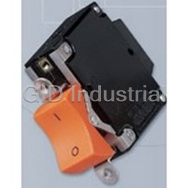
SENSATA AIRPAX 205-11-1-61-4-203-A

Description
Circuit Breaker Magnetic 2Pole 20A
205-11-1-61-4-203-A
Part Number
205-11-1-61-4-203-A
Price
Request Quote
Manufacturer
SENSATA AIRPAX
Lead Time
Request Quote
Category
Circuit Protection » Circuit Breaker
Specifications
Manufacturer
Sensata Airpax
Manufacturers Part #
205-11-1-61-4-203-A
Industry Aliases
205-11-1-61-4-203-A
Sub-Category
Circuit Breakers
Brand
Sensata Power Controls
Factory Pack Quantity
1
Datasheet

Extracted Text
APL/UPL, 205/295 Series Magnetic Circuit Protectors Introduction | 168 Single & Multi-Pole | 169 Barriers | 171 Configurations | 172 Operating Characteristics | 174 Delay Curves | 175 Specifications | 180 Decision Tables | 186 APL/UPL, 205/295 APL/UPL, 205/295 Series Hydraulic Magnetic Circuit Protectors INTRODUCTION The APL/UPL magnetic circuit protector provides reliable, While designed for industrial, military and information processing low-cost power switching, circuit protection and circuit applications, the APL is suitable for use in any situation where control. The handle opens and closes a circuit, under normal precision operation is required. Most versions of the APL load conditions, similar to an ON-OFF switch. Upon overload, family are recognized by UL per UL STD. 1077 as supplementary the internal mechanism trips, opens the contacts and forcibly protectors and certified by CSA per CSA STD. C22.2–No. 235 returns the handle to the OFF position. Since the protector is as supplementary protectors and are designated with the UPL “trip free,” the internal contacts will not remain closed in the prefix. presence of an overload, even though the handle is held in the ON position. Additionally, many versions of the UPL comply with the spacing requirements covered by IEC specifications 950 and 601 and VDE The APL/UPL line offers many configurations including series, specifications 0642 (EN60934) and are VDE approved and CE shunt and relay with a choice of delays and ratings. APL/UPL Compliant. Please contact the factory for assignment of a part multi-pole assemblies are available with a mix of current number. ratings, delays and internal circuit configurations. 168 APL/UPL, 205/295 Series - Introduction http://airpax.sensata.com/ 205/295 DUST SEALED PrOTECTOr APL/UPL, 205/295 Series Combining the proven mechanism of the APL/UPL circuit 205 breakers have standard full load current ratings from protector with a unique case design, the 205 version provides 0.050 amperes to 100 amperes and voltage ratings to 65Vdc increased voltage ratings plus a dust proof enclosure. and 277/480Vac. Like all Airpax magnetic protectors, the trip current rating is not affected by ambient temperature. All openings in the case (including arc blowout vent and handle) have been sealed with resilient rubber or mylar. In The 205 is recognized by UL and certified by CSA under the addition, case sections have been designed with tongue and Component program. Non UL-recognized versions of this groove construction to provide an overlapping closure. These series are designated 295. features make the 205 ideal for applications in harsh environments where reliable protection is essential. 2.020 MAX. APL/UPL [51.31] Single Pole Toggle .150 [3.81] 2.530 MAX. [64.26] .675 [17.14] 205/295 Single Pole Toggle .402 6-32 THD. (M3 ISO. THD. OPTIONAL) [10.21] .187 [4.75] DEEP (TWO PLACES) Note: Tolerance ± .015 [.38] unless noted. Dimensions in brackets [ ] are millimeters. .220 [5.59] 1.438 2.060 ± .010 [36.53] ON ON [52.32 ± 0.25] .750 MAX. [19.05] http://airpax.sensata.com/ APL/UPL, 205/295 Series - Single Pole 169 APL/UPL, 205/295 Mounting Details MULTI-POLE CIrCUIT PrOTECTOrS Multi-pole protectors are combined in an assembly with the One Pole actuating handles linked and the trip mechanisms internally .755 Ø 2X .156 coupled. A fault in either protected circuit opens all poles [19.18] [3.96] simultaneously. Applications include use in two-phase circuits, single-phase three-wire systems or in two or more related but electrically isolated circuits. A mix of delays, ratings and 2.060 1.448 configurations is possible, with the series type having any of [52.32] [36.78] the auxiliary switches listed. Combinations up to nine poles are available. .432 [10.97] MULTI-POLe DIMeNSIONS 2 pole “A” 1.515 [38.48] max 3 pole “A” 2.265 [57.53] max Two Pole 4 pole “A” 3.015 [76.58] max 1.530 Ø 4X .156 5 pole “A” 3.765 [95.63] max [38.86] [3.96] 6 pole “A” 4.515 [114.68] max 7 pole “A” 5.265 [133.73] max 8 pole “A” 6.015 [152.78] max 1.448 2.060 [36.78] [52.32] 9 pole “A” 6.765 [171.83] max Note: Dimension “A” varies with # of poles .432 .750 [10.97] [19.05] “A” (SEE TABLE) Three Pole 2.280 Ø 6X .156 [57.91] [3.96] ON ON 1.448 2.060 [36.78] [52.32] .75 ± .015 [19.05 ± .38] (TYP) .432 .750 .750 [10.97] [19.05] [19.05] Panel Mounting Tolerances: ±.005 [.13] unless noted. 170 APL/UPL, 205/295 - Multi-Pole http://airpax.sensata.com/ BArrIErS There are three barrier styles available for the 205/295, 215/285 protectors. Barrier style “B” is supplied for voltages between 200Vac and 250Vac inclusive. Barrier style “D” is required for voltages above 250Vac. Barrier style “C” is available for voltages up to 200Vac and is required when current ratings exceed 50 amperes. APL/UPL multi- pole protectors can be supplied with barriers at customer option. Consult factory. Barrier Style B 2.000 ± .020 [50.80 ± 0.51] .990 ± .020 [25.15 ± 0.51] 3.990 ± .020 [101.35 ± 0.51] Barrier Style C .990 ± .020 [25.15 ± 0.51] 2.490 ± .020 [63.25 ± 0.51] Barrier Style D .900 ± .020 [22.86 ± 0.51] 2.000 ± .020 [50.80 ± 0.51] .990 ± .020 [25.15 ± 0.51] 3.990 ± .020 [101.35 ± 0.51] Note: Tolerance ± .015 [.38] unless noted. Dimensions in brackets [ ] are millimeters. http://airpax.sensata.com/ APL/UPL, 205/295 Series - Barriers 171 APL/UPL, 205/295 APL/UPL, 205/295 CONFIGUrATIONS Series Trip Relay Trip The most popular configuration for magnetic protectors is the This permits the overload sensing coil to be placed in a series trip where the sensing coil and contacts are in series circuit which is electrically isolated from the trip contacts. with the load being protected. The handle position The coil may be actuated by sensors monitoring pressure, conveniently indicates circuit status. In addition to providing flow, temperature, speed, etc. Other typical applications conventional over-current protection, it’s simultaneously used include crowbar, interlock and emergency/rapid shutdown as an on-off switch. circuitry. Trip may be accomplished by voltage or current, which must be removed immediately upon tripping. Auxiliary Switch (Applies to Series Trip Only) Dual Coil This is furnished as an integral part of a series pole in Dual coil protectors provide remote shut down option and single or multi-pole assemblies. Isolated electrically from normal overcurrent protection in the confines of a single the protector’s circuit, the switch works in unison with breaker pole. This construction saves space by eliminating the the power contacts and provides indication at a remote need for an additional pole for the voltage trip function. location of the protector’s on-off status. Auxiliary switch contacts actuate simultaneously with the Voltage Trip main breaker contacts, and will open regardless of whether Sometimes called “dump circuits” or “panic trip circuits,” the breaker contacts are opened manually or electrically. For these units make it possible to open main power contacts auxiliary switch ratings below 6Vac or 5Vdc, an auxiliary with lower power inputs from one or more sources. This switch with gold contacts is available. Gold contacts are not configuration is becoming increasingly more important for recommended for load current above 100 milliamps. sensitive circuitry and denser packaging in automation The contacts on our optional rS auxiliary switch will open systems. Available in series, shunt, relay or dual coil only in the event of an electrical trip of the circuit breaker. configurations. Shunt Trip The shunt trip is designed for controlling two separate loads with one assembly. The control is established by providing overload protection for the critical load. When the current through this load becomes excessive and reaches the trip point, the protector will open and remove power from both loads simultaneously. The total current rating of both loads must not exceed the maximum contact rating. 172 APL/UPL, 205/295 - Configurations http://airpax.sensata.com/ Series Trip (See Note A) .675 ± .050 (17.15 ± 1.27) .625 ± .031 .281 ± .020 .281 ± .020 (15.88 ± 0.79) (7.14 ± 0.51) (7.14 ± 0.51) .280 (7.11) 1.940 1.940 [49.28] (49.28) LINE LINE LOAD LOAD (>50 AMP) ( 50 AMP) Series Trip with Auxiliary Switch 1.290 ± .031 .187 .295 (32.77 ± 0.79) [4.75] [7.49] .280 ± .031 (7.11 ± 0.79) RS 1.056 ± .031 .110 (26.82 ± 0.79) [2.79] REC 4 REG 4 .648 ± .031 .312 (16.46 ± 0.79) [7.92] LINE .187 NC [4.75] BREAKER IN OFF NO REC 5 POSITION REG 5 C LOAD Shunt, Relay and Dual Coil .625 ± .031 .625 ± .031 .281 ± .020 .281 ± .020 Notes: [15.88 ± 0.79] [15.88 ± 0.79] [7.14 ± 0.51] [7.14 ± 0.51] Tolerance ± .015 [.38] unless noted. Dimensions in brackets [ ] are millimeters. A Terminal sizes: 10-32 THD (<50 1.275 ± .020 [32.38 ± 0.51] AMP), ¼ -28 THD (>50 AMP) Metric Terminals (Optional), M5 x 0.8 THD (<50 AMP). 1.940 1.940 B Minimum useable thread [49.28] [49.28] length: 10-32 THD (.250 on .667 ± .020 .667 ± .020 [16.94 ± 0.51] [16.94 ± 0.51] breakers without terminal boards, .160 with terminal boards) ¼ -28 THD (.200). LINE LINE LINE LINE LINE LINE COIL COIL V. COIL LOAD LOAD LOAD RELAY COIL COIL LOAD LOAD RELAY LOAD LOAD SHUNT DUAL DUAL RELAY DUAL NO VOLTAGE TRIP COIL RATING TRIP COIL TRIP http://airpax.sensata.com/ APL/UPL, 205/295 Series - Configurations 173 APL/UPL, 205/295 APL/UPL, 205/295 OPErATING CHArACTErISTICS 0.050 AMPS TO 50 AMPS - PeRCeNTAge Of RATeD CURReNT VS TRIP TIMe IN SeCONDS AT +25°C Voltage Delay 100% 125% (Note A) 150% 200% 400% 600% 800% 1000% 40 No Trip May trip .050 max. .040 max. .030 max. .025 max. .020 max. .018 max. 41 No Trip May trip .6 to 7 .2 to 2 .020 to .4 .007 to .25 .004 to .15 .004 to .040 42 No Trip May trip 5 to 70 2 to 22 .4 to 3.8 .015 to 2 .006 to .4 .004 to .1 400 Hz 43 No Trip May trip 40 to 280 9 to 70 1.3 to 15 .2 to 3.75 .023 to .6 .010 to .050 49 No Trip .180 max. .120 max. .050 max. .022 max. .017 max. .017 max. .017 max. 50 No Trip May trip .032 max. .024 max. .020 max. .018 max. .016 max. .015 max. 51 No Trip .70 to 8 .40 to 4 .1 to 1.7 .02 to .30 .008 to .15 .004 to .06 .004 to .030 DC 52 No Trip 8 to 100 3 to 30 .7 to 10 .18 to 2.5 .030 to 1 .004 to .5 .004 to .3 53 No Trip 80 to 600 30 to 300 10 to 100 1.5 to 15 .1 to 5 .008 to .3 .007 to .07 59 No Trip .100 max. .070 max. .032 max. .020 max. .016 max. .016 max. .016 max. 60 No Trip May trip .040 max. .035 max. .030 max. .025 max. .020 max. .018 max. 61 No Trip 1 to 18 .4 to 4 .180 to 1.8 .03 to .3 .009 to .15 .003 to .1 .003 to .08 62 No Trip 10 to 120 6 to 60 2 to 22 .2 to 2 .05 to .75 .015 to .15 .01 to .10 50/60 Hz 69 No Trip .180 max. .120 max. .050 max. .022 max. .017 max. .017 max. .017 max. 64 No Trip .7 to 10 .35 to 4.5 .15 to 1.5 .05 to .4 .025 to .3 .020 to .22 .015 to .15 65 No Trip 8 to 80 5.5 to 55 2 to 20 .5 to 5 .2 to 2 .06 to 1 .016 to .60 66 No Trip 50 to 700 30 to 350 10 to 100 1.5 to 20 .7 to 7 .1 to 3 .02 to 2 70 No Trip May trip .040 max .035 max. .030 max. .025 max. .020 max. .018 max. 71 No Trip .35 to 14 .18 to 7.5 .10 to 3 .025 to 1 .015 to .30 .01 to .15 .007 to .10 DC 50/60 Hz 72 No Trip 6.5 to 115 3 to 65 1.2 to 20 .08 to 3 .018 to 2.5 .015 to .80 .009 to .25 73 No Trip 45 to 700 25 to 400 10 to 175 .75 to 20 .12 to 4.5 .025 to 1 .01 to .25 ABOVe 50 AMPS - PeRCeNTAge Of RATeD CURReNT VS TRIP TIMe IN SeCONDS AT +25°C Voltage Delay 100% 125% (Note A) 150% 200% 400% 600% 800% 1000% 50 No Trip May trip .100 max. .070 max. .032 max. .020 max. .020 max. .020 max. 51 No Trip .5 to 8 .3 to 4 .1 to 1.7 .02 to .3 .08 to .150 .004 to .060 .004 to .03 DC 52 No Trip 2.5 to 100 1.5 to 40 .62 to 15 .15 to 2.5 .03 to 1 .004 to .5 .004 to .3 59 No Trip .100 max. .070 max. .032 max. .020 max. .016 max. .016 max. .016 max. 60 No Trip May trip .120 max. .050 max. .022 max. .017 max. .017 max. .017 max. 61 No Trip .7 to 18 .35 to 4 .130 to 1.8 .030 to .3 .008 to .150 .003 to .1 .003 to .08 62 No Trip 10 to 120 6 to 60 2 to 22 .2 to 2 .050 to .750 .007 to .15 .005 to .10 50/60 Hz 69 No Trip .180 max. .120 max. .050 max. .022 max. .017 max. .017 max. .017 max. 64 No Trip May trip .2 to 8 .15 to 7.6 .05 to .73 .025 to .3 .020 to .22 .015 to .15 65 No Trip May trip 3 to 55 2 to 20 .3 to 5 .13 to 2 .06 to 1 .016 to .60 Notes: All trip curves and trip currents are specified with the protector mounted in the normal vertical position at ambient temperature of +25° C. Protectors do not carry current prior to application of overload. A: 130% for delays 49, 135% for delays 71, 72 and 73 Inrush Pulse Tolerance (typ) The following table provides a comparison of inrush pulse All trip curves and trip currents are specified with the tolerance with and without the inertial delay feature for each breaker mounted in the normal vertical position at ambient of the 50/60Hz delays. Pulse tolerance is defined as a single temperature of +25°C. Protectors do not carry current prior pulse of half sine wave peak current amplitude of 8 to application of overload. milliseconds duration that will not trip the circuit breaker. 174 APL/UPL, 205/295 - Operating Characteristics http://airpax.sensata.com/ 60Hz Delay Curves (typ) PULSe TOLeRANCeS A choice of delays are offered for 60Hz applications. Delays Delay Pulse Tolerance 60 and 69 are fast acting non-delayed tripping to protect 61, 62 12 times (approx.) rated current sensitive electronic equipment (not recommended where known inrush exists). Delay 61 has a short delay for general 61F, 62F 20 times (approx.) rated current purpose applications. Delay 62 is long enough to start 64, 65, 66 20 times (approx.) rated current certain types of motors and most transformers and 64F, 65F, 66F 35 times (approx.) rated current capacitor loads. Delay 63 is an extra long delay primarily for special motor applications. Note: These limits do not apply to dual coil and tapped coil units 10000 10000 1000 1000 DELAY 60 DELAY 61 100 100 10 10 1 1 .1 .1 .01 .01 .001 .001 0100 150 200 300 400 500 600 700 800 900 1000 0 100 150 200 300 400 500 600 700 800 900 1000 125 125 PERCENT OF RATED CURRENT PERCENT OF RATED CURRENT 10000 10000 1000 1000 DELAY 62 DELAY 69 100 100 10 10 1 1 .1 .1 .01 .01 .001 .001 0 100 150 200 300 400 500 600 700 800 900 1000 0100 150 200 300 400 500 600 700 800 900 1000 125 125 PERCENT OF RATED CURRENT PERCENT OF RATED CURRENT http://airpax.sensata.com/ APL/UPL, 205/295 Series - Delay Curves 175 TIME IN SECONDS TIME IN SECONDS MAY TRIP MAY TRIP TIME IN SECONDS TIME IN SECONDS MAY TRIP MAY TRIP APL/UPL, 205/295 Delays 64, 65 and 66 Delays 64, 65 and 66 are the latest 50/60Hz delays with short, medium and long trip times respectively. The patented protector design provides both increased tolerance to high inrush induced nuisance tripping and longer trip times at 600 percent. These delays are ideally suited for applications where thermal devices are presently used, such as motor protection or where short duration, high inrush currents are experienced. As shown in a typical motor start-up curve, the delay 66 will provide locked rotor and overload protection. Nuisance tripping is avoided since acceptable short periods of overload will not trip the protector. 10000 10000 1000 1000 DELAY 64 DELAY 65 100 100 10 10 1 1 .1 .1 .01 .01 .001 .001 0100 150 200 300 400 500 600 700 800 900 1000 0100 150 200 300 400 500 600 700 800 900 1000 125 125 PERCENT OF RATED CURRENT PERCENT OF RATED CURRENT 10000 1000 DELAY 66 100 10 1 .1 .01 .001 0100 150 200 300 400 500 600 700 800 900 1000 125 PERCENT OF RATED CURRENT 176 APL/UPL, 205/295 - Delay Curves http://airpax.sensata.com/ TIME IN SECONDS TIME IN SECONDS MAY TRIP MAY TRIP TIME IN SECONDS MAY TRIP DC/50/60Hz Delay Curves (typ) (Multi-frequency) A choice of delays is offered for combined DC and 50/60Hz operation. Delay 70 is fast acting, non-delayed tripping to protect sensitive electronic equipment (not recommended where known inrush exists). Delay 71 has a short delay for general purpose applications. Delay 72 is long enough to start certain types of motors and most transformer and capacitor loads. Delay 73 is an extra long delay primarily for special motor applications. 10000 10000 1000 1000 DELAY 70 DELAY 72 100 100 10 10 1 1 .1 .1 .01 .01 .001 .001 0100 150 200 300 400 500 600 700 800 900 1000 0 100 150 200 300 400 500 600 700 800 900 1000 125 125 PERCENT OF RATED CURRENT PERCENT OF RATED CURRENT 10000 10000 1000 1000 DELAY 71 DELAY 73 100 100 10 10 1 1 .1 .1 .01 .01 .001 .001 0 100 150 200 300 400 500 600 700 800 900 1000 0100 150 200 300 400 500 600 700 800 900 1000 125 125 PERCENT OF RATED CURRENT PERCENT OF RATED CURRENT http://airpax.sensata.com/ APL/UPL, 205/295 Series - Delay Curves 177 TIME IN SECONDS TIME IN SECONDS MAY TRIP MAY TRIP TIME IN SECONDS TIME IN SECONDS MAY TRIP MAY TRIP APL/UPL, 205/295 10000 DC Delay Curves (typ) 1000 A choice of delays is offered for DC applications. DELAY 52 Delays 50 and 59 provide fast acting, non-delayed 100 tripping to protect sensitive electronic equipment (not recommended where known inrush exists). 10 Delay 51 has a short delay for general purpose 1 applications. Delay 52 is long enough to start certain types of motors. Delay 53 is an extra long delay used .1 primarily for special motor applications. .01 .001 0 100 150 200 300 400 500 600 700 800 900 1000 125 PERCENT OF RATED CURRENT 10000 10000 1000 1000 DELAY 50 DELAY 53 100 100 10 10 1 1 .1 .1 .01 .01 .001 .001 0100 150 200 300 400 500 600 700 800 900 1000 0100 150 200 300 400 500 600 700 800 900 1000 125 125 PERCENT OF RATED CURRENT PERCENT OF RATED CURRENT 10000 10000 1000 1000 DELAY 51 DELAY 59 100 100 10 10 1 1 .1 .1 .01 .01 .001 .001 0100 150 200 300 400 500 600 700 800 900 1000 0100 150 200 300 400 500 600 700 800 900 1000 125 125 PERCENT OF RATED CURRENT PERCENT OF RATED CURRENT 178 APL/UPL, 205/295 - Delay Curves http://airpax.sensata.com/ TIME IN SECONDS TIME IN SECONDS MAY TRIP TIME IN SECONDS TIME IN SECONDS TIME IN SECONDS MAY TRIP MAY TRIP MAY TRIP 10000 400Hz Delay Curves (typ) 1000 DELAY 42 A choice of delays is offered for 400Hz applications. Delays 40 and 49 are fast acting, non-delayed 100 tripping to protect sensitive electronic equipment (not recommended where known inrush exists). 10 Delay 41 has a short delay for general purpose 1 applications. Delay 42 is long enough to start certain types of motor and most transformers and capacitor .1 loads. Delay 43 is an extra long delay primarily for special motor applications. .01 .001 100 150 200 300 400 500 600 700 800 900 1000 0 125 PERCENT OF RATED CURRENT 10000 10000 1000 1000 DELAY 43 DELAY 40 100 100 10 10 1 1 .1 .1 .01 .01 .001 .001 0100 150 200 300 400 500 600 700 800 900 1000 0 100 150 200 300 400 500 600 700 800 900 1000 125 125 PERCENT OF RATED CURRENT PERCENT OF RATED CURRENT 10000 10000 1000 DELAY 49 1000 DELAY 41 100 100 10 10 1 1 .1 .1 .01 .01 .001 .001 0100 150 200 300 400 500 600 700 800 900 1000 130 0 100 150 200 300 400 500 600 700 800 900 1000 125 PERCENT OF RATED CURRENT PERCENT OF RATED CURRENT http://airpax.sensata.com/ APL/UPL, 205/295 Series - Delay Curves 179 TIME IN SECONDS TIME IN SECONDS MAY TRIP MAY TRIP TIME IN SECONDS TIME IN SECONDS TIME IN SECONDS MAY TRIP MAY TRIP MAY TRIP APL/UPL, 205/295 APL/UPL SPECIFICATIONS Trip free Dual Coil Ratings Will trip open on overload, even when the handle is forcibly 5-65Vdc and 5-250Vac for three terminal configurations. held on or restrained. This prevents operator from damaging 5-120Vac and 5-120Vdc for four terminal configurations. Not the circuit by holding the handle in the ON position. available in delays 64, 65 and 66. Trip Indication APL Ratings The operating handle moves positively to the OFF position on overload. 0.050-50 amperes, 65Vdc, 250Vac maximum, 50/60Hz or 400Hz. 51-100 amperes at 65Vdc and 120Vac maximum. ratings of Ambient Operation 0.050-20 amperes at 277Vac, 50/60Hz are available upon Operates normally in temperatures between –40°C and +85°C. request. Insulation Resistance Auxiliary Switch Ratings (APL/UPL, 205/295) Not less than 100 megohms at 500Vdc. rEC4 and rEC5 are rated at 10 amperes, 250Vac or 3 amperes, 50Vdc. rEG4 and rEG5 are rated at 0.1 amperes, Dielectric Strength 125Vac. Withstands 1500Vac at 60Hz for 60 seconds or 1800Vac for one second from terminal to terminal, and from auxiliary UPL Ratings switch terminal to main terminal. UPL protectors are UL STD. 1077 (File No. E-66410) and CSA STD. C22.2–No. 235 (File No. Lr-26229) recognized as endurance supplementary protectors in the following configurations and Per UL 1077 (6000 operations at rated load plus 4000 ratings. Consult factory for further information. operations with no load). Tested at a maximum rate of 6 times per minute. rating above 50 amperes operate a minimum of Configurations 5000 operations. Series, Shunt, relay, Auxiliary Switch, Switch Only, Dual Coil, No Voltage. Shock Withstands 100G or more without tripping while carrying full Poles rated current per MIL-Std-202, Method 213, Test Condition I. One through nine. Instantaneous types (delay 40, 50, 60 and 49, 59, 69) and dual coil configurations are tested at 80% of rated current. Moisture Resistance Protectors mounted in the handle down position are to be Designed to meet the requirements of MIL-PrF-55629 when tested with no current applied (per MIL-PrF-55629). tested in accordance with Method 106 of MIL-Std-202. Vibration Salt Spray (Corrosion) Withstands 10G without tripping while carrying full rated Designed to meet the requirements of MIL-PrF-55629 when current per MIL-Std-202, Method 204, Test Condition A. tested in accordance with Method 101 of MIL-Std-202. Instantaneous types (delay 40, 50, 60 and 49, 59, 69) and dual coil configurations are tested at 80% of rated current. APPROxIMATe WeIgHT PeR POLe ReCOMMeNDeD TORQUe SPeCIfICATIONS Ounces grams Component Torque (in-lbs) 3.7 103 6-32 Mounting Inserts 6 to 8 M3 Mounting Screws 4 to 5 10-32 Screw Terminals 13 to 14 M5 Stud Terminals 13 to 14 1/4 - 20 Stud Terminals 25 to 30 Where applicable, mechanical support must be provide to the terminals when applying torque 180 APL/UPL, 205/295 - APL/UPL Specifications http://airpax.sensata.com/ APL/UPL - NOMINAL DCR / IMPeDANCe Resistance (ohms) Impedance (ohms) Impedance (ohms) Current DC Delays AC, 50/60Hz Delays AC, 400Hz Delays Ratings (Amps) Dual Coil 600, 61, 62 64, 65, 66 50 59 51, 52, 53 60 69 40, 49 41, 42, 43 51, 52, 53 71, 72, 73 Dual Coil 61, 62 0.05 162 540 460 640 174 419 582 691 1975 1195 0.10 35.4 105 155 150 42.5 103.4 119.0 160 495 284 0.50 1.2 4.2 4.5 5.6 1.9 4 4.1 6.2 22 12 1.0 .236 1.02 1.2 1.41 .41 .955 1.08 1.56 5.01 2.72 5.0 .021 .048 .059 .070 .030 .045 .048 .068 .240 .140 10.0 .0060 .0121 .0140 .0160 .0075 .0105 .0134 .0174 .0520 .0283 15.0 .0040 .0067 .0092 .0100 .0038 .0068 .0070 .0120 .0260 .0140 20.0 .0032 .0047 .0052 .0070 .0024 .0049 .0050 .0069 .0140 .0088 30.0 .0021 .0036 .0036 .0040 .0022 .0032 .0035 .0037 .0079 .0043 50.0 .0020 .0024 .0026 .0023 .0020 .0020 .0025 .0030 .0036 .0028 Notes: DCR and impedance based on 100% rated current applied and stablized a minimum of one hour. Tolerance: .02 amperes to 2.5 amperes, ± 20%; 2.6 amperes to 20 amperes, ± 25%; 21 amperes to 50 amperes, ± 50%. Consult factory for special values and for coil impedance of delays not shown APL/UPL - RATINgS Configurations Current Ratings (Amps) Maximum Voltage Ratings Interrupting Capacity (Amps) Series fuse 0.050 - 50 65Vdc 5000 None 0.050 - 100 65Vdc 3000 None 0.050 - 60 120Vac (50/60Hz) 1000 None 0.050 - 50 120Vac (50/60Hz) 5000 4X (120 max.) Series and Shunt 0.050 - 20 277Vac (50/60Hz) 5000 4X 0.050 - 50 250Vac (50/60Hz) 5000 4X (120 max.) 0.050 - 50 120Vac (400Hz) 1500 None 21 - 50 250Vac (400Hz) 1000 None 0.050 - 20 250Vac (400Hz) 2100 None 0.050 - 50 50Vdc — — 0.050 - 50 120Vac (50/60Hz) — — relay 0.050 - 50 120Vac (400Hz) — — 0.050 - 50 250Vac (50/60Hz-400Hz) — — 50 amperes max. 65Vdc — — — 100 amperes max. 32Vdc — — — Switch Only 50 amperes max. 250Vac (50/60Hz) — — — 50 amperes max. 250Vac (400Hz) — — — Notes: DC units do not require series fusing. 277Vac: A circuit protector with this voltage rating is intended for 277Vac per pole single phase source only usage. (e.g.) If a two or three pole breaker is marked 277Vac, all line terminals must be connected to the same phase, assuming the 277Vac is taken from line to neutral of a three phase 277/480Vac system. http://airpax.sensata.com/ APL/UPL, 205/295 Series - APL/UPL Specifications 181 APL/UPL, 205/295 205/295 SPECIFICATIONS Trip free Dual Coil Ratings Will trip open on overload, even when the handle is forcibly 5-65Vdc and 5-250Vac for three terminal configurations. held on or restrained. This prevents operator from damaging 5-120Vac and 5-120Vdc for four terminal configurations. Not the circuit by holding the handle in the ON position. available in delays 64, 65 and 66. Trip Indication 295 Ratings The operating handle moves positively to the OFF position on 0.05-100 amperes, 65Vdc, 0.050-60 amperes, 250Vac maximum, overload. 50/60Hz or 400Hz. 51-100 amperes at 65Vdc and 120Vac maximum. 30 amperes at 277/480Vac for 3 phase WYE Ambient Operation Connected applications only. ratings to 20 amperes at 277Vac, Operates normally in temperatures between –40°C and +85°C. 50/60Hz are available upon request. Insulation Resistance 205 Ratings Not less than 100 megohms at 500Vdc. 205 protectors are UL (File No. E-66410) and CSA (File No. Lr-26229) recognized as Component Appliance Controls in the Dielectric Strength following configurations and ratings. Withstands 1500Vac at 60Hz for 60 seconds or 1800Vac for one second from terminal to terminal, and from auxiliary switch 205D Ratings terminal to main terminal. 205D protectors are UL-1500 (Marine Ignition Protection) recognized at 65Vdc or 250Vac to 60 amperes maximum at endurance 1000 AIC. Consult factory for application details. Per UL 1077 (6000 operations at rated load plus 4000 operations with no load). Tested at a maximum rate of six times per Configurations minute. rating above 50 amperes operate a minimum of 5000 Series, Shunt, relay, Auxiliary Switch, Switch Only. operations. Poles One through nine. 205/295 - NOMINAL DCR / IMPeDANCe Resistance (ohms) Impedance (ohms) Impedance (ohms) Current DC Delays AC, 50/60Hz Delays AC, 400Hz Delays Ratings (Amps) Dual Coil 600, 61, 62 64, 65, 66 50 59 51, 52, 53 60 69 40, 49 41, 42, 43 51, 52, 53 71, 72, 73 Dual Coil 61, 62 0.05 162 540 506 576 174 419 582 691 1975 1195 0.10 35.4 105 125 150 42.5 103.4 119.0 160 495 284 0.50 1.2 4.2 4.5 5.6 1.9 4 4.1 6.2 22 12 1.0 .236 1.02 1.2 1.41 .41 .955 1.08 1.56 5.01 2.72 5.0 .021 .048 .059 .070 .030 .045 .048 .068 .240 .140 10.0 .0060 .0121 .0140 .0160 .0075 .0105 .0134 .0174 .0520 .0283 15.0 .0040 .0067 .0092 .0100 .0038 .0068 .0070 .0120 .0260 .0140 20.0 .0032 .0047 .0052 .0070 .0024 .0049 .0050 .0069 .0140 .0088 30.0 .0021 .0036 .0036 .0040 .0022 .0032 .0035 .0037 .0079 .0043 50.0 .0020 .0024 .0026 .0023 .0020 .0020 .0025 .0030 .0036 .0028 Notes: DCR and impedance based on 100% rated current applied and stablized a minimum of one hour. Tolerance: .02 amperes to 2.5 amperes, ± 20%; 2.6 amperes to 20 amperes, ± 25%; 21 amperes to 50 amperes, ± 50%. Consult factory for special values and for coil impedance of delays not shown 182 APL/UPL, 205/295 - 205/295 Specifications http://airpax.sensata.com/ 205/295 - RATINgS Configurations Current Ratings (Amps) Maximum Voltage Ratings Interrupting Capacity (Amps) Series fuse 0.050 - 50 65Vdc 5000 None 0.050 - 100 65Vdc 3000 None 0.050 - 60 120Vac (50/60Hz) 1000 None 0.050 - 50 120Vac (50/60Hz) 5000 4X (125 max.) Series and Shunt 0.050 - 20 277Vac (50/60Hz) 5000 4X 0.050 - 50 250Vac (50/60Hz) 5000 4X (125 max.) 0.050 - 50 120Vac (400Hz) 1500 None 21 - 50 250Vac (400Hz) 1000 None 0.050 - 20 250Vac (400Hz) 2100 None 0.050 - 30 277/480Vac (50/60Hz) 5000 4X (80A max.) Series Only 0.050 - 30 277/480Vac (50/60Hz) 1500 None 0.050 - 50 50Vdc — — 0.050 - 50 120Vac (50/60Hz) — — relay 0.050 - 50 120Vac (400Hz) — — 0.050 - 50 250Vac (50/60Hz-400Hz) — — 50 amperes max. 65Vdc — — — 100 amperes max. 32Vdc — — — Switch Only 50 amperes max. 250Vac (50/60Hz) — — — 50 amperes max. 250Vac (400Hz) — — — Notes: DC units do not require series fusing. 277Vac: A circuit protector with this voltage rating is intended for 277Vac per pole single phase source only usage. (e.g.) 60 ampere units and 277/480Vac units require a 2 x 4 inch interphase barrier for mulitpole units. If a two or three pole protector is marked 277Vac, all line terminals must be connected to the same phase, assuming the 277 Vac is taken from line to neutral of a three phase 277/480Vac system. http://airpax.sensata.com/ APL/UPL, 205/295 Series - 205/295 Specifications 183 APL/UPL, 205/295 205/295, MPL SPECIFICATIONS Auxiliary Switch Ratings Configurations (APL/UPL, 205/295) Series only with and without auxiliary switch. rEC4 and rEC5 are rated at 10 amperes, 250Vac or 3 amperes, 50Vdc. rEG4 and rEG5 are rated at 0.1 amperes, 125Vac. Poles One, two or three. Moisture Resistance Designed to meet the requirements of MIL-PrF-55629 when Shock tested in accordance with Method 106 of MIL-Std-202. Withstands 100G or more without tripping while carrying full rated current per MIL-Std-202, Method 213, Test Condition I. Salt Spray (Corrosion) Instantaneous types (delay 40, 50, 60 and 49, 59, 69) are Designed to meet the requirements of MIL-PrF-55629 when tested at 80% of rated current. Breakers mounted in the tested in accordance with Method 101 of MIL-Std-202. handle down position are to be tested with no current applied (per MIL-PrF-55629). MPL Ratings MPL protectors are UL (File No. E-41607) and CSA (File No. Vibration Lr-26229) recognized as manual, across the line starters, in Withstands 10G without tripping while carrying full rated the following configurations and ratings. Consult factory for current per MIL-Std-202, Method 204, Test Condition A. further information. Instantaneous types (delay 40, 50, 60 and 49, 59, 69) are tested at 80% of rated current. 184 APL/UPL, 205/295 - MPL Specifications http://airpax.sensata.com/ ReCOMMeNDeD TORQUe SPeCIfICATIONS APPROxIMATe WeIgHT PeR POLe Component Torque (in-lbs) Ounces grams 6-32 Mounting Inserts 6 to 8 3.7 103 M3 Mounting Screws 4 to 5 10-32 Screw Terminals 13 to 14 M5 Stud Terminals 13 to 14 1/4 - 20 Stud Terminals 25 to 30 Where applicable, mechanical support must be provide to the terminals when applying torque MPL - RATINgS Current Ratings (Amps) Maximum Voltage Ratings Horsepower, Single Phase Ratings Three Phase (Note A) 0.050 - 50 65Vdc 1 — 0.050 - 50 120Vac (50/60Hz) 3 7.5 0.050 - 20 240Vac (50/60Hz) 3 5 0.050 - 20 277Vac (50/60Hz) 3 5 Note: AC units require maximum of 4X rated series fusing: DC units do not require series fusing. A: Two or three poles breaking http://airpax.sensata.com/ APL/UPL, 205/295 Series - MPL Specifications 185 APL/UPL, 205/295 APL/UPL DECISION TABLES Notes: How to Order A The most common current values for 100% of rated current are The ordering code for APL/UPL circuit protectors may be those listed. Please consult an Airpax office orsales representa- tive for other values. determined by following the steps in the decision tables shown here. B All APL/UPL protectors are constructed with stainless steel springs and plated parts. As noted in the specifications, all meet The coding given permits a self-assigning part number; other normal requirements for moisture and salt spray resistance. If configurations may require a factory assigned part number. fungus resistance is required in addition to moisture and salt spray resistance, special procedures and markings are employed. Typical examples are units with mixed ratings, combinations of styles or constructions not listed in the third decision table, etc. C Terminals will be supplied as #10-32 threaded studs up to 50 amperes. Above this amperage terminals will be ¼ -28 threaded With these, it is suggested that order entry be by description studs. All standard units will be supplied with a hex nut and two and/or drawings and a part number will be assigned. Additionally, flat washers on each threaded terminal. it is a standard policy to establish a factory assigned part number D When metric threaded inserts are specified, breakers rated at wherever a descriptive drawing exists to provide cross 50 amperes and below will be supplied with metric threaded reference, traceability and manufacturing control. terminals. For breakers rated above 50 amperes, ¼ -28 threaded terminals will be supplied. When specifying a protector for AC motor start or high inrush E Black handle standard. applications, the peak amplitude and surge duration should be specified for factory assistance in rating selection. For example, the code shown is the code for a two pole UPL protector with series trip, 20 ampere rating, 50/60Hz. short time delay construction in all poles. To determine the ordering number for your particular APL/UPL unit, simply follow the steps shown. You may use this number to place an order or as a reference for further questions you may have. 186 APL/UPL, 205/295 - APL/UPL Decision Tables http://airpax.sensata.com/ UPL 11 - 1 - 61- 203 http://airpax.sensata.com/ APL/UPL, 205/295 Series - APL/UPL Decision Tables 187 APL/UPL, 205/295 205/295 DECISION TABLES How to Order The ordering code for 205/295 circuit protectors may be 3 6 ( ) Third Decision Sixth Decision Note A determined by following the steps in the decision tables Nominal Amperage Rating Internal Configuration shown here. -0 Switch only Current Code Ratings (Amps) (Omit 4th and 5th decisions) For example, the code shown is the code for a UL 101 .100 recognized, two pole protector with series trip, 20 5 Fifth Decision -1 Series 251 .250 ampere rating at 240Vac max., 50/60Hz short time delay Maximum Voltage Rating construction in all poles. -1REC4 Series with auxiliary switch 501 .500 *.110 quick connect terminals -1 32Vdc 751 .750 To determine the ordering number for your particular -1REC5 Series wtih auxiliary switch -2 65Vdc 205/295 unit, simply follow the steps shown. You may use 102 1.0 *.187 quick connect terminals -3 120Vac this number to place an order or as a reference for further 252 2.50 4 -1REG4 Series with auxiliary switch Fourth Decision questions you may have. -4 250Vac (single phase) (gold contacts) *.110 quick 502 5.0 Hz and Delay connect terminals -4A 250Vac multi-phase style B 752 7.50 40* 400Hz 150% instant trip barrier required 1 First Decision -1RS Series with alarm switch electrical trip turret terminals 103 10.0 Type -5 41* 400Hz short delay 277/480Vac* (series only - notes D and F.) Y connection only 153 15.0 -3 Shunt 42* 400Hz long delay 205 Dust sealed protector UL -6 277 Vac* ratings and construction 203 20.0 43* 400Hz motor start -5 Relay -7 125/250Vac (205 D) 205D Marine ignition protected 303 30.0 49* 400Hz 130% instant trip Multi-pole units with mixed construction, poles numbered left to right when viewed from terminal end. -8 65Vdc/250Vac (70-73 delay) 295 Dust sealed protector 353 35.0 50 DC 150% instant trip *Can be used for Solder Terminals also. *30 Amp max. 403 40.0 51 DC short delay 503 *50.0 52 DC long delay 2 Second Decision 603 60.0 53* DC motor start Poles 703 70.0 59 DC 125% instant trip -0* Switch only (no overload sensing) 803 80.0 60 50/60Hz 150% instant trip -1 Single pole unit Example: 903 90.0 61 50/60Hz short delay -11 Two pole unit 205 - 11 -1 - 61- 4 - 203 104 *100.0 62 50/60Hz long delay -111 Three pole unit 64 50/60Hz short delay Standard current ratings listed. -1111 Four pole unit 1 24 3 56 (high pulse) For other ratings, please consult the factory. *Use 0 in place of 1 when ordering switch only. 65 50/60Hz long delay *Switch only ratings. (high pulse) 66* 50/60Hz motor start (high pulse) Notes: 69 50/60Hz 125% instant trip 7 Seventh Decision A The most common current values for 100% of rated current are those listed. Please D For detailed barrier and wiring information, request Airpax specification AM-433. 70* DC-50/60Hz 150% instant trip Optional consult an Airpax office or sales representative for other values. 71* DC-50/60Hz short delay -A Metric thread mounting inserts E When metric threaded inserts are specified, breakers rated at 50 amperes and and terminals (note E) B All 205/295 protectors are constructed with stainless steel springs and plated parts. below will be supplied with metric threaded terminals. For breakers rated above 72* DC-50/60Hz long delay As noted in the specifications, all meet normal requirements for moisture and salt 50 amperes, ¼ -28 threaded terminals will be supplied. -H International handle markings 73* spray resistance. If fungus resistance is required in addition to moisture and salt DC-50/60Hz motor start delay -M Fungus (note B) spray resistance, special procedures and markings are employed. F Available in multi-pole, series only for multiphase applications. For addition of inertial delay, add an “F” to any delay number, except 40, 50, 60 and 70. -O Black handle C Terminals will be supplied as #10-32 threaded studs up to 50 amperes. Above this (standard handle color is white) *Not available above 50 amperes. amperage terminals will be ¼ -28 threaded studs. All standard units will be supplied with a hex nut and 2 flat washers on each threaded terminal. 188 APL/UPL, 205/295 - APL/UPL Decision Tables http://airpax.sensata.com/ 3 6 ( ) Third Decision Sixth Decision Note A Nominal Amperage Rating Internal Configuration -0 Switch only Current Code Ratings (Amps) (Omit 4th and 5th decisions) 101 .100 5 Fifth Decision -1 Series 251 .250 Maximum Voltage Rating -1REC4 Series with auxiliary switch 501 .500 *.110 quick connect terminals -1 32Vdc 751 .750 -1REC5 Series wtih auxiliary switch -2 65Vdc 102 1.0 *.187 quick connect terminals -3 120Vac 252 2.50 4 -1REG4 Series with auxiliary switch Fourth Decision -4 250Vac (single phase) (gold contacts) *.110 quick 502 5.0 Hz and Delay connect terminals -4A 250Vac multi-phase style B 752 7.50 40* 400Hz 150% instant trip barrier required 1 First Decision -1RS Series with alarm switch electrical trip turret terminals 103 10.0 Type -5 41* 400Hz short delay 277/480Vac* (series only - notes D and F.) Y connection only 153 15.0 -3 Shunt 42* 400Hz long delay 205 Dust sealed protector UL -6 277 Vac* ratings and construction 203 20.0 43* 400Hz motor start -5 Relay -7 125/250Vac (205 D) 205D Marine ignition protected 303 30.0 49* 400Hz 130% instant trip Multi-pole units with mixed construction, poles numbered left to right when viewed from terminal end. -8 65Vdc/250Vac (70-73 delay) 295 Dust sealed protector 353 35.0 50 DC 150% instant trip *Can be used for Solder Terminals also. *30 Amp max. 403 40.0 51 DC short delay 503 *50.0 52 DC long delay 2 Second Decision 603 60.0 53* DC motor start Poles 703 70.0 59 DC 125% instant trip -0* Switch only (no overload sensing) 803 80.0 60 50/60Hz 150% instant trip -1 Single pole unit Example: 903 90.0 61 50/60Hz short delay -11 Two pole unit 205 - 11 -1 - 61- 4 - 203 104 *100.0 62 50/60Hz long delay -111 Three pole unit 64 50/60Hz short delay Standard current ratings listed. -1111 Four pole unit 1 24 3 56 (high pulse) For other ratings, please consult the factory. *Use 0 in place of 1 when ordering switch only. 65 50/60Hz long delay *Switch only ratings. (high pulse) 66* 50/60Hz motor start (high pulse) 69 50/60Hz 125% instant trip 7 Seventh Decision 70* DC-50/60Hz 150% instant trip Optional 71* DC-50/60Hz short delay -A Metric thread mounting inserts and terminals (note E) 72* DC-50/60Hz long delay -H International handle markings 73* DC-50/60Hz motor start delay -M Fungus (note B) For addition of inertial delay, add an “F” to any delay number, except 40, 50, 60 and 70. -O Black handle (standard handle color is white) *Not available above 50 amperes. http://airpax.sensata.com/ APL/UPL, 205/295 Series - APL/UPL Decision Tables 189 APL/UPL, 205/295
Frequently asked questions
How does Electronics Finder differ from its competitors?

Is there a warranty for the 205-11-1-61-4-203-A?
Which carrier will Electronics Finder use to ship my parts?
Can I buy parts from Electronics Finder if I am outside the USA?
Which payment methods does Electronics Finder accept?
Why buy from GID?

Quality
We are industry veterans who take pride in our work

Protection
Avoid the dangers of risky trading in the gray market

Access
Our network of suppliers is ready and at your disposal

Savings
Maintain legacy systems to prevent costly downtime

Speed
Time is of the essence, and we are respectful of yours
Related Products
Sensata Technologies 203-2-1-52-103-5-3-18
Circuit Breaker Supplementary Protector 1Pole 5A 250VAC 203-2-1-63-502-4-1-1
Circuit Breaker Supplementary Protector 1Pole 2.5A 250VAC 203-2-1-66F-252-G-1-16
Circuit Breaker Supplementary Protector 2Pole 10A 250VAC 203-22-1-60-103-C-1-32
Sensata Technologies 203-22-1-61-502-E-1-1-A
Circuit Breaker Supplementary Protector 2Pole 10A 250VAC 203-22-1-62F-103-4-3-13
Request a Quote

The quote request has been received
Close

Facing challenges or have inquiries? Feel free to contact us!
Call Us +1-469-283-2440
What they say about us
FANTASTIC RESOURCE
One of our top priorities is maintaining our business with precision, and we are constantly looking for affiliates that can help us achieve our goal. With the aid of GID Industrial, our obsolete product management has never been more efficient. They have been a great resource to our company, and have quickly become a go-to supplier on our list!
Bucher Emhart Glass
EXCELLENT SERVICE
With our strict fundamentals and high expectations, we were surprised when we came across GID Industrial and their competitive pricing. When we approached them with our issue, they were incredibly confident in being able to provide us with a seamless solution at the best price for us. GID Industrial quickly understood our needs and provided us with excellent service, as well as fully tested product to ensure what we received would be the right fit for our company.
Fuji
HARD TO FIND A BETTER PROVIDER
Our company provides services to aid in the manufacture of technological products, such as semiconductors and flat panel displays, and often searching for distributors of obsolete product we require can waste time and money. Finding GID Industrial proved to be a great asset to our company, with cost effective solutions and superior knowledge on all of their materials, it’d be hard to find a better provider of obsolete or hard to find products.
Applied Materials
CONSISTENTLY DELIVERS QUALITY SOLUTIONS
Over the years, the equipment used in our company becomes discontinued, but they’re still of great use to us and our customers. Once these products are no longer available through the manufacturer, finding a reliable, quick supplier is a necessity, and luckily for us, GID Industrial has provided the most trustworthy, quality solutions to our obsolete component needs.
Nidec Vamco
TERRIFIC RESOURCE
This company has been a terrific help to us (I work for Trican Well Service) in sourcing the Micron Ram Memory we needed for our Siemens computers. Great service! And great pricing! I know when the product is shipping and when it will arrive, all the way through the ordering process.
Trican Well Service
GO TO SOURCE
When I can't find an obsolete part, I first call GID and they'll come up with my parts every time. Great customer service and follow up as well. Scott emails me from time to time to touch base and see if we're having trouble finding something.....which is often with our 25 yr old equipment.
ConAgra Foods