

 Manufacturers
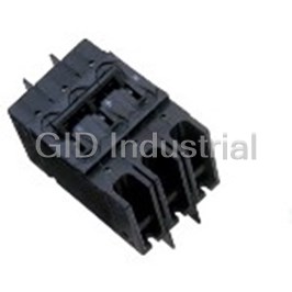
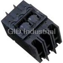
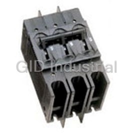
SENSATA AIRPAX 219-3-1-66-8-2-70
Description
Circuit Protection Misc Hydraulic Magnetic Circuit Protector
219-3-1-66-8-2-70
Part Number
219-3-1-66-8-2-70
Price
Request Quote
Manufacturer
SENSATA AIRPAX
Lead Time
Request Quote
Category
Circuit Protection » Circuit Protection Misc
Specifications
Manufacturer
Sensata Airpax
Manufacturers Part #
219-3-1-66-8-2-70
Industry Aliases
219-3-1-66-8-2-70
Sub-Category
Miscellaneous Circuit Protection
Brand
Sensata Power Controls
Factory Pack Quantity
1
Datasheet

Extracted Text
209 Series Magnetic Circuit Protectors Introduction • 187 249 Power Selector System • 189 Multi-Pole • 191 Configurations • 193 Operating Characteristics • 195 Delay Curves • 196 Specifications • 199 Decision Tables • 201 209/219/229/249/279 Series Hydraulic Magnetic Circuit Protectors INTRODUCTION The 209, E-Frame circuit breaker combines power switching with Utilizing the hydraulic-magnetic principle, the 209 family adapts accurate, reliable circuit protection in a compact single or multi- itself to local applications and environments. Temperature pole unit. The unit is ideal for branch circuit applications such as conditions, which affect fuses and other thermal devices, are EDP, air conditioners, panel boards and lighting controls. not a concern. The magnetic /ampere turn principle minimizes nuisance tripping due to temperature variations. The 209 is actually a family of circuit breakers available in one through six pole assemblies with a variety of configurations Inrush currents, due to ferroresonant transformers, lamps and terminal styles to meet your application needs. First in this and capacitive filters, are now becoming more significant. family is the 209, a general purpose E-Frame circuit breaker Recognizing the need for this type of protection, Airpax offers the which complies with UL Standard 489. Other members of the unique inertial delay which is standard for all 50/60Hz time delay family include the 219, for manual controller applications, units, but may be deleted where inrush is not a problem. No extra which complies to UL Standard 508, the 229, for supplementary cost or special order is required. protectors applications, which complies to UL Standard 1077, and the 299, a Special Construction version. The 209 family of circuit breakers withstands high pulses without tripping or affecting normal delay curves. This performance, however, does not derate or sacrifice protection. 209 Series - Introduction 187 http://airpax.sensata.com 209/219/229 MAGNETIC CIRCUIT PROTECTORS Terminal Style DIMENSION “A” 209 E-Frame circuit breakers may be specified with either Number of Poles Dimensions “A” screw terminals, stud or solderless connectors. 1 1.026 ± .010 [26.06 ± 3.30] A choice of front or back connected terminal styles is available. 2 2.072 [52.63] Max The back connected terminal style is available with stud 3 3.108 [78.94] Max terminals only. Front terminal style is available with either 4 4.144 [105.26] Max screw terminals or solderless connectors. 5 5.180 [131.57] Max Refer to Sixth Decision Table for front connected terminal 6 6.216 [157.89] Max information. Barriers for back connected terminal styles are supplied on multi-pole units only. Line and load connections may be made to either terminal and terminals will be identified as shown. 2.610 Front Connected Solderless Connector [66.29] .700 1.220 [17.78] A (Back Mounted) [30.99] MAX. .220 .125 .200 [5.59] [3.18] [5.08] .562 [14.27] .530 .485 [13.46] [12.32] +.015 -.005 2.250 +0.38 5.800 [57.15] -0.13 [147.32] 2.156 [54.76] 4.844 2.750 35º [123.04] [69.85] 1.125 35º 1.375 2.375 [28.58] [34.92] [60.32] 4.750 [120.65] 2X 6-32 MTG. INSERT .160 MIN. SCREW DEPTH [4.06] .310 MAX. SCREW DEPTH [7.87] 3.0 MM ISO THD. OPTIONAL .220 [5.59] Back Connected Stud Terminal 3.550 [90.17] A (Front Mounted) .700 2.610 [17.78] [66.29] .220 MAX. [5.59] 2.156 [54.76] +.015 5.125 2.250 -.005 2.750 [130.18] [57.15] +0.38 [69.85] -0.13 1.125 1.375 [28.58] 3.550 [34.92] [90.17] 4.750 [120.65] 2X 6-32 MTG. INSERT .160 MIN. SCREW DEPTH [4.06] .310 MAX. SCREW DEPTH [7.87] 3.0 MM ISO THD. OPTIONAL 0-50 AMPS 10-32 STUDS .625 ±.062 [15.88 ±1.57] LONG 51-100 AMPS 1/4-20 STUDS Note: Tolerance ± .015 [.38] unless noted. Dimensions in brackets [ ] are millimeters. .750 ±.062 [19.05 ±1.57] LONG IELR Series - Introduction 188 209 (E-frame) 249 POWER SELECTOR BREAKER SYSTEM Trip Time Delay The 249 Power Selector Breaker System combines magnetic-hydraulic branch circuit overload protection Three inverse time delays are available to permit close coor- and a power system selector switch in one device. dination with various loads. Delays 51 and 61 are short delays for electronic loads. Delays 52 and 62 are medium The 249 is designed to allow selection of any one of delays for mixed loads. Delays 53 and 63 are long delays for two, three or four independent power systems. This is motor loads. accomplished with fool-proof sliding-gate handle covers. The number of sliding covers is one less than Current and Voltage Ratings the number of power systems. With this arrangement, Single pole and multi-pole breaker ratings are available up it is impossible to switch “ON” more than one power to 100 amperes, 240Vac or 125Vdc. The special configuration system at a time. for Marine use has a 120V/240Vac rating for current rating up to 100 amperes. Since the 249 Power Selector Breaker System is listed as a Branch Circuit Breaker per UL 489 and power Master Drawing switching is accomplished by UL listed breakers, it is Standard circuit breaker terminal and configurations are usually not necessary to include additional branch shown. For other types, consult factory. service protection. Standard options available include terminals for front or back connections, choice of trip time delay, current ratings to 100 amperes and single or multi-pole sections. 209 Series - 249 Power Selector Breaker System 189 http://airpax.sensata.com 249 Master Drawing 2.610 .800 [66.29] 1.220 Width [20.32] [30.99] (SEE TABLE) MAX. .125 .200 (TYP.) .562 6-32 MTG. Insert [3.18] [5.08] [14.27] .160 [4.06] MIN. screw depth .310 [7.87] MAX. screw depth .530 (TYP) .485 [13.46] [12.32] +.015 -.005 2.250 +0.38 [57.15] -0.13 5.800 [147.32] 2.156 4.844 2.750 [54.76] [123.04] [69.85] 1.125 2.375 1.375 [28.58] [60.32] [34.92] 4.750 [120.65] 4X MTG. SLOT .220 1.026 Clearance for [5.59] [26.06] 8-32 Screw (TYP.) (TYP.) 1/4 - 20 Studs 10 - 32 or 1/4 - 20 Screw Terminals .390 3.550 [9.91 [90.17] 2.610 .375 [66.29] [9.53] 2.156 [54.76] 5.125 [130.18] 3.550 [90.17] 4.750 Note: Tolerance ± .015 [.38] unless noted. Dimensions in brackets [ ] are millimeters. [120.65] (REF) .750 [19.05] DIMENSIONS Number of Poles Width 9 9.324 [236.83] Max 8 8.288 [210.52] Max 6 6.216 [157.89] Max 4 4.144 [105.26] Max 2 2.072 [52.63] Max 209 Series - 249 Power Selector Breaker System 190 209 (E-frame) 209/219/229/279 209/219/229 MULTI-POLE CIRCUIT PROTECTORS Common-Trip Construction Three Phase, Four Pole Includes Control Protector All multi-pole protectors contain an internal trip bar which Remote shutdown of equipment is sometimes necessary or opens all poles in the event of an overload in any pole. desirable in today’s sophisticated equipment. The 219 four Handles are ganged externally for simultaneous actuation. pole assembly fills this need for three phase operation. Three of the four poles are designed for the circuit’s proper Individual poles may differ in ratings, delays and operating current and over-current protection. The fourth configurations, providing an almost limitless number of pole may be designed for instantaneous tripping by logic combinations. circuitry, interlocks or from a manual remote site or control. The control power required would be quite low, with voltages Multi-pole protectors (up to 6 poles) easily satisfy special from 5 to 125Vdc, or 5 to 240Vac available. The fourth pole modern day circuitry. Series, shunt, relay and auxiliary switch construction is optional. It may be either series, shunt or construction add to the versatility of design engineering. relay, depending on the application required. When Airpax’s sales engineering force is ready to assist in proper specifying, both the minimum trip voltage and Hz are required. unit selection, both for equipment protection and economical Factory consultation is readily available. design. Front Connected Solderless Connector (Back Mounted) 2.610 2.072 .700 [66.29] (52.63) 1.220 [17.78] MAX. [30.99] .220 .125 MAX. .200 [5.59] .562 [3.18] [5.08] [14.27] .530 .485 See available [13.46] [12.32] mounting brackets +.015 below -.005 2.250 +0.38 [57.15] -0.13 5.800 2.156 [147.32] 4.844 2.750 [54.76] [123.04] [69.85] 1.125 1.375 2.375 [28.58] [34.93] [60.32] 4.750 [120.65] 4X 6-32 MTG. INSERT .160 MIN. SCREW DEPTH [4.06] .310 MAX. SCREW DEPTH [7.87] 2X MTG. SLOT 3.0 MM ISO THD. OPTIONAL 1.026 .220 CLEARANCE FOR [5.59] [26.06] 8-32 SCREW 10 - 32 or 1/4 - 20 Screw Terminals Slotted Mounting Bracket Short Mounting Bracket terminal codes -2, -3, -5, terminal codes -2C, -3C, .390 -7, -3M, -5M, -7M -5C, -7C [9.91] .145 [3.68] SCALE: 3/1 SCALE: 3/1 209 Series - Multi-Pole 191 http://airpax.sensata.com DIMENSIONS Number of Poles Width 1 1.026 ± .010 [26.06 ± .254] 2 2.072 [52.63] Max 3 3.108 [78.94] Max 4 4.144 [105.26] Max 5 5.180 [131.57] Max 6 6.216 [157.89] Max Note: Tolerance ± .015 [.38] unless noted. Dimensions in brackets [ ] are millimeters Caution: Elongation of mounting holes may be necessary for units with more than 6 poles and units up to 12 poles due to tolerance compounding 209 Series - Multi-Pole 192 209 (E-frame) 229D (MARINE) & 279 (COMMUNICATION) 209/219/229 CONFIGURATIONS UL-1500 Ignition Protection Series Trip The 229D family is certified to UL-1500 which covers The most popular configuration for magnetic protectors is Ignition Protected circuit protectors. This specification the series trip, where the sensing coil and contacts are in requires devices to be used in accordance with the series with the load being protected. The handle position requirements of U.S. Coast Guard and Fire Protection conveniently indicates circuit status. In addition to Standard for Pleasure and Commercial Motor Craft, ANSI/ providing conventional overcurrent protection, it’s MFPA No. 302. simultaneously used as an ON-OFF switch. The ratings available are 100 amperes or less at 65Vdc or SEE NOTE A 240Vac. Maximum IC, 1000 amperes. Consult factory for LINE application details. The 299D series is available with interlocking to prevent on LOAD board and shore power being used simultaneously. Combination of ON-OFF switching the protection function offers a simplified solution for your electrical systems. 3.550 [90.17] UL 489A Communications Equipment Protection The 279 Series complies with the requirements of UL 489A, Circuit Breakers for use in Communication Equipment, meeting the need for protection at higher DC voltages. .750 The available ratings are 100 amperes or less at 160Vdc. [19.05] Maximum short circuit interrupting current is 5000 amperes. The 279 series available only in a series trip configuration. Please consult Sensata for specific application details. Auxiliary Switch This is furnished as an integral part of a series pole in single or multi-pole assemblies. Isolated electrically from the protector’s circuit, the switch works in unison with the power contacts and provides indication at a remote location of the protector’s ON-OFF status. (Applies to Series Trip Only) C NO NC 3.550 [90.17] 3.128 MAX. [79.45] REF. FROM BACK OF .295 MOUNTING [7.49] PANEL. .110 -IREC4 [2.79] -IREG4 1.563 [39.70] Quick Connect Terminals .312 [7.92] .187 .750 -IREC5 [4.75] [19.05] -IREG5 209 Series - Configurations 193 http://airpax.sensata.com 219/229 CONFIGURATIONS Relay Trip This permits the overload sensing coil to be placed in a circuit SEE NOTE A which is electrically isolated from the trip contacts. The coil LINE may be actuated by sensors monitoring pressure, flow, LOAD temperature, speed, etc. Other typical applications include RELAY 1.000 crowbar, interlock and emergency/rapid shutdown circuitry. [25.40] RELAY Trip may be accomplished by voltage or current, which must be removed after trip. 3.550 LINE [90.17] Dual Coil COIL Providing for both a voltage trip and a current trip function in COIL LOAD Relay Trip a magnetic circuit protector is common practice. These two 1.250 coil protectors provide remote or automatic opening of one or [31.75] more circuits with a low level signal. The voltage coil will trip the protector instantaneously while .750 [19.05] the current coil provides normal inverse time delays. The Dual Coil voltage coil is not rated for continuous duty and therefore, the .190 [4.83] voltage must be removed when the breaker trips. Since both coils are housed within the same pole, the space savings are substantial. This option is not available with 64, 65 or 66 delays. Shunt Trip The shunt trip is designed for controlling two separate loads with one assembly. The control is established by providing overload protection for the critical load. When the current through this SEE NOTE A load becomes excessive and reaches the trip point, the protector LINE will open and remove power from both loads simultaneously. The LOAD total current rating of both loads must not exceed the maximum SHUNT contact rating. Voltage Trip LINE 3.550 V. COIL [90.17] Sometimes called “dump circuits” or “panic trip circuits,” these units make it possible to open main power contacts with Shunt Trip LOAD lower power inputs from one or more sources. This configuration is becoming increasingly more important for 1.250 [31.75] sensitive circuitry and denser packaging in automation systems. .750 [19.05] Available in series, shunt or relay configurations. Dual Coil .190 [4.83] Note: Tolerance ± .015 [.38] unless noted. Dimensions in brackets [ ] are millimeters. A: 0-50 Amps, 10-32 Studs .625 ± .062 [15.88 ± .157 ] Long, 51-100 Amps, 1/4 - 20 Studs, .750 ± .062[19.05 ± .157 ] Long. 209 Series - Configurations 194 209 (E-frame) OPERATING CHARACTERISTICS Inrush Pulse Tolerance INRUSH PULSE TOLERANCE The table shown above provides a comparison of inrush pulse tolerance with and without the inertial delay feature Delay Pulse Tolerance for each of the 50/60Hz delays. Pulse tolerance is defined as 61, 62, 63 8 times rated current a single pulse of half sine wave peak current amplitude of 8 64 minimum 20 times rated current milliseconds duration that will not trip the circuit breaker. 65 minimum 25 times rated current The table at right provides a reference guide for selecting 66 minimum 30 times rated current the inertial delay feature. Consult factory for further assis- Note: These limits do not apply to dual coil and tapped coil units tance. PERCENTAGE OF RATED CURRENT VS TRIP TIME IN SECONDS AT +25°C Delay 100% 125% 150% 200% 400% 600% 800% 1000% 41 & 41F No Trip May Trip .6 to 7 .2 to 2 .03 to .40 .01 to .1 .009 to .060 .008 to .050 42 & 42F No Trip May Trip 7 to 70 2 to 20 .1 to 3 .01 to .2 .009 to .09 .008 to .08 43 & 43F No Trip May Trip 60 to 500 20 to 200 2 to 30 .01 to .1 .009 to .09 .008 to .08 51 & 51F No Trip .4 to 7 .2 to 2 .12 to 1 .03 to .3 .012 to .1 .009 to .07 .008 to .05 52 & 52F No Trip 8 to 80 2.5 to 45 .7 to 20 .2 to 3 .05 to 1 .01 to .5 .009 to .08 53 & 53F No Trip 100 to 900 50 to 500 20 to 200 2 to 25 .015 to 5 .01 to .15 .009 to .09 61 No Trip .6 to 5 .3 to 2 .1 to .8 .03 to .3 .015 to .1 .01 to .07 .009 to .06 62 No Trip 12 to 120 6 to 55 2 to 18 .3 to 3 .05 to 1 .016 to .1 .01 to .08 63 No Trip 70 to 800 45 to 450 20 to 200 2 to 30 .3 to 4 .02 to .25 .012 to .15 64 No Trip .6 to 5 .3 to 3 .1 to 1.5 .03 to .5 .02 to .4 .01 to .3 .008 to .25 65 No Trip 12 to 100 6 to 50 2 to 18 .3 to 3 .05 to 2 .016 to 1.6 .01 to 1 66 No Trip 70 to 800 45 to 450 20 to 200 2 to 30 .3 to 9 .02 to 5 .013 to 3 Notes: *279 is available only with DC delays 209 Series - Operating Characteristics 195 http://airpax.sensata.com 10000 209/219/229 DELAY CURVES 1000 DELAY 61 100 50/60Hz Delay Curves (typ) 10 A choice of delays is offered for 50/60Hz applications. 1 Delay 61 is a short delay for general purpose .1 applications. Delay 62 is long enough to start certain types of motors and most transformer and capacitor .01 loads. .001 Delay 63 is a long delay for special motor applications. 0100 150 200 300 400 500 600 700 800 900 1000 125 PERCENT OF RATED CURRENT Delays 64, 65 and 66 are the latest 50/60Hz delays with short, medium and long trip times respectively. The patented breaker design provides both increased tolerance to high inrush induced nuisance tripping and longer trip times at 600 percent. These delays are ideally suited for applications where thermal devices 10000 are presently used, such as motor protection or where 1000 short duration, high inrush currents are experienced. DELAY 62 As shown in a typical motor start-up curve, the delay 66 100 will provide locked rotor and overload protection. Nuisance tripping is avoided, since acceptable short 10 periods of overload will not trip the breaker. 1 All trip curves and trip currents are specified with the .1 breaker mounted in the normal vertical position at ambient temperature of +25°C. For test and .01 measurement purposes, the breakers should not carry .001 current prior to application of overload for calibration 0 100 150 200 300 400 500 600 700 800 900 1000 125 test. For other than vertical mount position, consult PERCENT OF RATED CURRENT factory. 10000 1000 DELAY 63 100 10 1 .1 .01 .001 0 100 150 200 300 400 500 600 700 800 900 1000 125 PERCENT OF RATED CURRENT 209 Series - Delay Curves 196 TIME IN SECONDS TIME IN SECONDS TIME IN SECONDS MAY TRIP MAY TRIP MAY TRIP 209 (E-frame) 209/219/229/279 DELAY CURVES 60Hz Delay Curves (typ) 10000 1000 DELAY 64 100 10 1 .1 .01 .001 0 100 150 200 300 400 500 600 700 800 900 1000 125 PERCENT OF RATED CURRENT 10000 1000 DELAY 65 100 10 1 .1 .01 .001 0 100 150 200 300 400 500 600 700 800 900 1000 125 PERCENT OF RATED CURRENT 10000 1000 DELAY 66 100 10 1 .1 .01 .001 0 100 150 200 300 400 500 600 700 800 900 1000 125 PERCENT OF RATED CURRENT 209 Series - Delay Curves 197 http://airpax.sensata.com TIME IN SECONDS TIME IN SECONDS TIME IN SECONDS MAY TRIP MAY TRIP MAY TRIP 209/219/229 DELAY CURVES DC Delay Curves (typ) 400Hz Delay Curves(typ) (279 is available only with DC delays) 10000 10000 1000 1000 DELAY 51 DELAY 41 100 100 10 10 1 1 .1 .1 .01 .01 .001 .001 0 100 150 200 300 400 500 600 700 800 900 1000 0 100 150 200 300 400 500 600 700 800 900 1000 125 125 PERCENT OF RATED CURRENT PERCENT OF RATED CURRENT 10000 10000 1000 1000 DELAY 42 DELAY 52 100 100 10 10 1 1 .1 .1 .01 .01 .001 .001 0 100 150 200 300 400 500 600 700 800 900 1000 0 100 150 200 300 400 500 600 700 800 900 1000 125 125 PERCENT OF RATED CURRENT PERCENT OF RATED CURRENT 10000 10000 1000 DELAY 43 1000 DELAY 53 100 100 10 10 1 1 .1 .1 .01 .01 .001 0 100 150 200 300 400 500 600 700 800 900 1000 .001 125 0 100 150 200 300 400 500 600 700 800 900 1000 PERCENT OF RATED CURRENT 125 PERCENT OF RATED CURRENT 209 Series - Delay Curves 198 TIME IN SECONDS TIME IN SECONDS TIME IN SECONDS MAY TRIP MAY TRIP MAY TRIP TIME IN SECONDS TIME IN SECONDS TIME IN SECONDS MAY TRIP MAY TRIP MAY TRIP 209 (E-frame) 209/219/229 SPECIFICATIONS Trip Free NOMINAL DCR / IMPEDANCE Will trip open on overload, even when forcibly held on. This prevents the operator from damaging the circuit by holding Resistance (ohms) Impedance (Ohms) the handle in the ON position. Current Ratings DC Delays AC, 50/60Hz Delays (Amps) Trip Indication 51, 52, 53 61, 62, 63 The operating handle moves positively to the OFF position 0.10 112.0 117.0 on overload. 1.0 0.97 1.0 Environmental Specifications 5.0 .042 .044 Moisture and fungus resistance is provided by the use of 10.0 .011 .012 moisture resistant finishes. Special springs and treatment 20.0 .0042 .0043 for all ferrous parts eliminate inherent moisture-related 30.0 .0030 .0031 problems. The use of fungi inert cases and handles avoids 50.0 .0018 .0019 fungus-related problems. 80.0 .0014 .0015 Current Ratings 100 .0008 .0009 209/219/229 may be supplied with these ratings: DC, Notes: DCR and impedance based on 100% rated current applied and 50/60Hz, 400Hz, 0.1 to 100 amperes. 279 types may be stablized a minimum of one hour. supplied with DC ratings only, 0.1 to 100 amperes. Tolerance: .1 amperes to 1.0 amperes, ± 10%; 1.1 amperes to 5.0 amperes, ± 15%; 5.1 amperes to 15 amperes, ± 25%; 15.1 amperes to 100 amperes, ± 50% or = .001 Ohms, whichever is greater. Voltage Ratings On 209/219/229, voltages up to and including 240Vac, 50/60Hz or 400Hz, or 125Vdc are available. Multi-pole units can be supplied for 277Vac/480Vac, 50/60Hz. 279 types are available with a voltage of 160Vdc. All units will be marked with the standard maximum voltage. UL Listed breakers will APPROXIMATE CIRCUIT BREAKER WEIGHT be labeled with the UL listed voltage. # of Poles Ounces 1 9 oz Auxiliary Switch Ratings 2 1 lb, 3 oz When supplied shall be S.P.D.T. configuration with a 3 2 lb maximum rating of 10 amperes 250Vac. 4 2 lb, 7 oz Mounting Considerations 5 3 lb A three-inch spacing must be provided between the circuit 6 3 lb, 12 oz breaker and vent and any conductive surface. If closer than three inches is necessary, then an insulator must be installed on the conductive surface. Solderless Connectors RECOMMENDED TORQUE SPECIFICATIONS Connectors are rated AL9 CU. and accept either copper or aluminum conductors. Units are suitable for use with both Component Torque (in-lbs) 60° and 75° wire. Optional pressure plate for fine stranded 6-32 Mounting Inserts 6 to 8 wire is available. Contact factory for details. M3 Mounting Screws 4 to 5 1/4-20 Screw Terminals 35 to 40 10-32 Stud Terminals 13 to 14 M5 Stud Terminals 13 to 14 1/4 - 20 Stud Terminals 40 to 45 Where applicable, mechanical support must be provide to the terminals when applying torque 209 Series - Specifications 199 http://airpax.sensata.com 209 SERIES AGENCY APPROVALS 219 MANUAL MOTOR CONTROLLERS AGENCY APPROVALS Volts (Volts) Rated Current (Amps) Interrupting Capacity (Amps) Volts (Volts) Rated Current (Amps) Interrupting Capacity (Amps) Voltage (V) Frequency (Hz) Min. Poles UL/CSA VDE UL 489 & CSA VDE Voltage (V) Frequency (Hz) Min. Poles UL VDE UL 508 VDE 65 DC 1 .10-100 - 25000 - 125 DC 1 .10-100 .10-100 5000 4000 125 DC 1 .10-100 .10-100 10000 4000 120/240 50/60 2 .10-100 - 5000 - 125/250 DC 2 .10-20 - 5000 - 120/240 50/60 2 .10-100 - 10000 - 120 50/60 1 only .10-50 - 10000 - 240 50/60 1 .10-100 .10-100 5000 4000 120/240 50/60 2 .10-100 - 5000 - 240/415 50/60 2 - .10-100 - 4000 120/240 50/60 2 only .10-50 - 10000 - 277 50/60 1 .10-100 - 5000 - 240 50/60 1 .10-100 .10-100 5000 4000 277/480 50/60 2 .10-100 - 5000 - 240 400 1 .10-100 - 2500 - 277/480 50/60 2 .10-100 - 10000(1) - 279 Circuit Breakers for use in Communications Equipment 480 50/60 2 .10-100 - 10000(1) - Voltage (V) Frequency (Hz) Min. Poles UL/CSA VDE UL489A VDE 600 50/60 2 .10-77 - 10000(1) - 160 DC 1 .10-100 - 5000 - 250 400 1 .10-100 - 5000 - Notes: (1) With 225 A maximum series fuse General notes 229 SUPPLEMENTARY PROTECTORS* AGENCY APPROVALS Volts (Volts) Rated Current (Amps) Interrupting Capacity (Amps) All supplementary protectors are of the overcurrent (OC) type Frequency Min. The family of protectors has been evaluated for end use application for Voltage (V) (Hz) UG FW Phase Poles TC OL UL/CSA VDE UL 1077 & CSA No. 235 VDE use group (UG) A and D 125 DC A, D 0 - 1 1 0 .10-100 .10-100 U2, 10000 / U1, 5000 4000 125 DC A, D 0, 3 - 1 1 0 .10-100 .10-100 U2, 5000 / U1, 5000 4000 The terminals (FW) – Terminals are coded as follows: 125/250 DC A, D 0, 3 - 2 1 1 .10-20 - U1, 5000 - 0 – Suitable for factory wiring only 300 DC A, D 0, 3 - 2 1 0 .10-100 - U1, 5000 - 1 – Line terminals evaluated for field wiring 125/250 50/60 A, D 0 1 2 1 1 .10-100 - U2, 5000 - 2 – Load terminals evaluated for field wiring 125/250 50/60 A, D 0 1 2 1 0 .10-100 - U1, 10000 - 3 – Line and Load terminals evaluated for field wiring 250 50/60 A, D 0, 3 1 1 1 0 .10-100 - U1, 5000 - 277 50/60 A, D 0, 3 1 1 1 1 .10-100 - U1, 5000 - The maximum voltage ratings for which the protectors have been tested 277/480 50/60 A, D 0 1 & 3 2 1 1 .10-100 - C2, 10000(1) / C1, 10000 - are shown in the chart 277/480 50/60 A, D 0, 3 1 & 3 2 1 0 .10-100 - U2, 5000 / U1, 5000 - 347/600 50/60 A, D 0 1 & 3 2 1 0 .10-100 - C1, 10000(1) - The current is the amperage range that the protectors have been tested 347/600 50/60 A, D 0, 3 1 & 3 2 1 0 .10-100 - U1, 5000 - 480 50/60 A, D 0 3 3 1 0 .10-100 - C2, 10000(1) / C1, 10000 - The tripping current (TC) – Tripping Current is coded as a percentage of 600 50/60 A, D 0 3 3 1 0 .10-77 - C2, 10000(1) / C1, 10000 - the ampere rating: 125/250 400 A, D 0, 3 1 2 2 0 .10-100 - U2, 1500 / U1, 2000 - 0 – Tripping current is less than 125% of ampere rating 229D Supplementary Protectors (Ignition Protected) 1 – Tripping current is in the range of 125% to 135% of ampere rating Voltage (V) Frequency UG FW Phase Min. TC OL UL/CSA VDE UL1500 & CSA VDE 2 – Tripping current is more than 135% of ampere rating (Hz) Poles 3 – Tripping current is 135% and meets MCCB trip time requirements 65 DC A, D 0, 3 - 1 1 1, (0, .10-100 - U2, 1000/U1,1000 - CSA ) 250 50/60 A, D 0, 3 1 1 1 1, (0, .10-100 - U2, 1000/U1, 1000 The overload rating (OL) - Designates whether the protector or family of CSA) protectors has been tested for general use or motor starting applications. 229G Supplementary Protectors (Generator Use – UL489 Field wired) 0 – tested at 1.5 times amp rating for general use Voltage (V) Frequency UG FW Phase Min. TC OL UL/CSA VDE UL1077 & CSA VDE 1 – tested at 6 times AC rating or 10 times DC rating for motor starting (Hz) Poles 277/480 50/60 A, D 0, 3 3 3 1 1 .10-100 - U2, 2500 - The short circuit current rating (SC) – The short circuit rating in amperes 347/600 50/60 A, D 0, 3 3 3 1 1 .10-77 - U2, 2000 - following a letter and number designating the test conditions and any 239 Supplementary Protectors (Marine) calibration following the short circuit test is defined below: Voltage (V) Frequency UG FW Phase Min. TC OL UL/CSA VDE UL1077 & CSA VDE (Hz) Poles C – Indicates short circuit test was conducted with series overcurrent 250 50/60 A, D 0, 3 1 & 3 1 1 1 .10-100 - U1, 5000 - protection 125/250 50/60 A, D 0, 3 1 2 1 1 .10-100 - U1, 5000 - U – Indicates short circuit test was conducted without series overcurrent 240 50/60 - - 1 & 3 1 - - - .10-100 - 4000 protection 240/415 50/60 - - 3 3 - - - .10-100 - 4000 1 – Indicates a recalibration was not conducted as part of the short Notes: (1) With 225A maximum series fuse circuit testing 2 – Indicates a recalibration was performed as part of the short circuit *219 also applicable for CSA approval only. testing 3 – Indicates recalibration was performed along with the dielectric and voltage withstand for “Suitable for Further Use” rating 209 Series - Agency Approvals 200 209 (E-frame) Con gurations Terminal Terminal Connect Panel Mount 209/219/229/279 DECISION TABLES -1 Solderless connector front front (Note A) How to Order -2 Solderless connector front back* -2C Solderless connector front back** The ordering code for 209, E-Frame Circuit Breakers may be -3 10-32 screw (100 amps max.) bus connect back (Note C)* determined by following the steps in the decision tables -3C 10-32 screw (100 amps max.) bus connect back (Note C)** shown here. † -4 10-32 screw (50 amps max.) front front -5 10-32 screw (50 amps max.) front back* The coding given permits a self-assigning part number for -5C 10-32 screw (50 amps max.) front back** standard configurations. Factory part numbers are assigned -6 1/4 - 20 screw (100 amps max.) front front to units with mixed ratings, combinations of styles or con- -7 1/4 - 20 screw (100 amps max.) front back* struction not listed in the Third Decision Table, etc. With † -7C 1/4 - 20 screw (100 amps max.) front back** these, it is suggested that order entry be by description and/ or drawings, and a part number will be established. -8 10 - 32 stud (50 amps max.) back front (Note D) -9 1/4 - 20 stud (100 amps max.) back front (Note D) Additionally, it is standard policy to establish a factory- -3M M5 x 0.8 screw (100 amps max.) bus connect back (Note C)* assigned part number whenever a descriptive drawing -4M M5 x 0.8 screw (50 amps max.) front front exists to insure cross reference, traceability and manufac- -5M M5 x 0.8 screw (50 amps max.) front back* turing control. -6M M6 x 1.0 screw (100 amps max.) front front -7M M6 x 1.0 screw (100 amps max.) front back* When specifying a breaker for AC motor start or high inrush -8M M5 x 0.8 stud (50 amps max.) back front (Note D) applications, the peak amplitude and surge duration should -9M M6 x 1.0 stud (100 amps max.) front front (Note D) be specified for factory assistance in rating selection. 209 is * U 489 Listed units are rated to 100A maximum ** U 489A Listed units are rated to 160Vdc maximum * Back panel mount style supplied with slotted mounting bracket. a UL listed circuit breakers under file no. E53739 per UL 489. Solderless connector will accept #14 through 0 copper or #12 through 0 aluminum wire. ** Back panel mount style supplied with short mounting bracket. 279 is a UL listed under file no. E192808 per UL 489A. 219 is a UL recognized “Manual Motor Controller” under file no. E41607 per UL 508. 229 is a UL recognized supplementary protector under file no. E66410 per UL 1077. For example, the following is the code for a single pole breaker with series trip, 50/60Hz, medium inertial delay, 120/240Vac maximum voltage ratings, solderless connector with mounting foot added to the line side of the breaker to facilitate back panel mounting and a current rating of 10.0 amperes. To determine the ordering number of your particular 209 unit, simply follow the steps shown. You may use this number to place an order or as a reference for further questions you may have. Notes: C Line terminals are 10-32 screws for bus connection to 100 amperes. A 6-32 inserts for front mounting are provided on all units. M3 ISO metric Load terminals are 10-32 screws to 50 amperes and solderless mounting inserts are available and are specified by adding -A at the end connectors from 50 to 100 amperes. of the ordering code above. D An anti-flashover barrier is supplied between poles on all multi-pole B The auxiliary switch is located on the right-hand pole (viewed from versions with 10-32 stud and 1/4-20 stud terminals per UL requirement. terminal end) unless specified otherwise. Auxiliary switches are available on all front or back panel mounts (series construction only). E The standard current values for 100% of rated current are those listed in If more than one auxiliary switch is specified use “2R” through “6R” as the Seventh Decision Table. Non-listed values can be readily supplied, required. in general without delayed delivery. Please contact an Airpax office or sales representative. 209 Series - Decision Tables 201 http://airpax.sensata.com Con gurations Terminal Terminal Connect Panel Mount -1 Solderless connector front front (Note A) -2 Solderless connector front back* -2C Solderless connector front back** -3 10-32 screw (100 amps max.) bus connect back (Note C)* -3C 10-32 screw (100 amps max.) bus connect back (Note C)** † -4 10-32 screw (50 amps max.) front front -5 10-32 screw (50 amps max.) front back* -5C 10-32 screw (50 amps max.) front back** -6 1/4 - 20 screw (100 amps max.) front front -7 1/4 - 20 screw (100 amps max.) front back* † -7C 1/4 - 20 screw (100 amps max.) front back** -8 10 - 32 stud (50 amps max.) back front (Note D) -9 1/4 - 20 stud (100 amps max.) back front (Note D) -3M M5 x 0.8 screw (100 amps max.) bus connect back (Note C)* -4M M5 x 0.8 screw (50 amps max.) front front -5M M5 x 0.8 screw (50 amps max.) front back* -6M M6 x 1.0 screw (100 amps max.) front front -7M M6 x 1.0 screw (100 amps max.) front back* -8M M5 x 0.8 stud (50 amps max.) back front (Note D) -9M M6 x 1.0 stud (100 amps max.) front front (Note D) * U 489 Listed units are rated to 100A maximum ** U 489A Listed units are rated to 160Vdc maximum * Back panel mount style supplied with slotted mounting bracket. Solderless connector will accept #14 through 0 copper or #12 through 0 aluminum wire. ** Back panel mount style supplied with short mounting bracket. 209 (E-frame) 249 POWER SELECTOR BREAKER SYSTEM DECISION TABLES How to Order To evolve a convenient ordering system for most applications, the following code has been developed. If a system is required which is not covered below, please consult factory or describe in detail. The number shown as an example describes a 120 volt, three section system, such as may be used on a boat with a port and starboard shore power receptacle and an AC generator. The breaker rating for the shore power is 30 amperes and for the generator 20 amperes in this example. 1/4 -20 screw type terminals and a medium time delay are specified. 209 Series - Decision Tables 203 http://airpax.sensata.com
Frequently asked questions
How does Electronics Finder differ from its competitors?

Is there a warranty for the 219-3-1-66-8-2-70?
Which carrier will Electronics Finder use to ship my parts?
Can I buy parts from Electronics Finder if I am outside the USA?
Which payment methods does Electronics Finder accept?
Why buy from GID?

Quality
We are industry veterans who take pride in our work

Protection
Avoid the dangers of risky trading in the gray market

Access
Our network of suppliers is ready and at your disposal

Savings
Maintain legacy systems to prevent costly downtime

Speed
Time is of the essence, and we are respectful of yours
Related Products
Circuit Protection Misc Circuit Protection Device
Circuit Protection Misc Power Selector Breaker System 249-6-C-100-50-100-2-62-1
Circuit Protection Misc Power Selector Breaker System 249-6-C-30-60-30-3-65-2
Circuit Protection Misc Power Selector Breaker System 249-6-C-30-70-30-2-63-2
Circuit Protection Misc Power Selector Breaker System 249-6-C-50-50-100-3-62-1
Circuit Protection Misc Power Selector Breaker System 249-6-C-50-50-30-3-62-1
Request a Quote

The quote request has been received
Close

Facing challenges or have inquiries? Feel free to contact us!
Call Us +1-469-283-2440
What they say about us
FANTASTIC RESOURCE
One of our top priorities is maintaining our business with precision, and we are constantly looking for affiliates that can help us achieve our goal. With the aid of GID Industrial, our obsolete product management has never been more efficient. They have been a great resource to our company, and have quickly become a go-to supplier on our list!
Bucher Emhart Glass
EXCELLENT SERVICE
With our strict fundamentals and high expectations, we were surprised when we came across GID Industrial and their competitive pricing. When we approached them with our issue, they were incredibly confident in being able to provide us with a seamless solution at the best price for us. GID Industrial quickly understood our needs and provided us with excellent service, as well as fully tested product to ensure what we received would be the right fit for our company.
Fuji
HARD TO FIND A BETTER PROVIDER
Our company provides services to aid in the manufacture of technological products, such as semiconductors and flat panel displays, and often searching for distributors of obsolete product we require can waste time and money. Finding GID Industrial proved to be a great asset to our company, with cost effective solutions and superior knowledge on all of their materials, it’d be hard to find a better provider of obsolete or hard to find products.
Applied Materials
CONSISTENTLY DELIVERS QUALITY SOLUTIONS
Over the years, the equipment used in our company becomes discontinued, but they’re still of great use to us and our customers. Once these products are no longer available through the manufacturer, finding a reliable, quick supplier is a necessity, and luckily for us, GID Industrial has provided the most trustworthy, quality solutions to our obsolete component needs.
Nidec Vamco
TERRIFIC RESOURCE
This company has been a terrific help to us (I work for Trican Well Service) in sourcing the Micron Ram Memory we needed for our Siemens computers. Great service! And great pricing! I know when the product is shipping and when it will arrive, all the way through the ordering process.
Trican Well Service
GO TO SOURCE
When I can't find an obsolete part, I first call GID and they'll come up with my parts every time. Great customer service and follow up as well. Scott emails me from time to time to touch base and see if we're having trouble finding something.....which is often with our 25 yr old equipment.
ConAgra Foods