

 Manufacturers
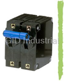
SENSATA AIRPAX IEG1-1-65F-7.50-C-01-V
Description
IEG1-1-65F-7.50-C-01-V
Part Number
IEG1-1-65F-7.50-C-01-V
Price
Request Quote
Manufacturer
SENSATA AIRPAX
Lead Time
Request Quote
Category
Circuit Protection » Circuit Breaker Accessories
Specifications
Manufacturer
Sensata Airpax
Manufacturers Part #
IEG1-1-65F-7.50-C-01-V
Sub-Category
Circuit Breaker Accessories
Brand
Sensata Airpax
Series
IAG
Factory Pack Quantity
1
Datasheet

Extracted Text
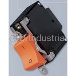
IAG/IUG/IEG/CEG/LEG Series Magnetic Circuit Protectors Introduction • 99 Poles • 100 Handles • 103 Configurations • 108 Operating Characteristics • 110 Delay Curves • 111 Specifications • 115 Decision Tables • 117 IAG/IUG/IEG/CEG/LEG Series Hydraulic Magnetic Circuit Protectors INTRODUCTION The Airpax™ IAG/IUG/IEG/CEG/LEG magnetic circuit protectors equipment, vending and amusement machines, military provide low-cost power switching, reliable circuit protection applications and wherever precision operation is required. and accurate circuit control for equipment in the international Temperature differences which affect fuses and other thermal marketplace. devices are not a concern. IEG models meet IEC spacing requirements which is mandatory One important feature of this protector line is a “trip free” action, for equipment that must comply with IEC specifications 601 and which means the circuit will trip in the presence of an overload 950 and VDE specifications 0804 and 0805. In addition, they are even though the handle is held in the ON position. The delay UL Recognized as supplementary protectors per UL STD. 1077, mechanism senses the fault and the contacts open. CSA Certified as supplementary protectors per CSA C22.2–No. 235, VDE Approved to VDE 0642 (EN60934), CCC Approved and CE The IAG/IUG/IEG/CEG/LEG is available in a wide variety of Compliant. IAG models are for those applications where the unit’s configurations including series, series with auxiliary switch, inherent attributes are desired, but compliance with the various shunt and relay with a choice of delays and ratings in either standards is not required. DC, 50/60Hz or 400Hz versions. Handles come in seven different colors and international markings are standard. Single or multi- Designed using the latest in sensitive hydraulic magnetic pole versions are available, with a variety of pole arrangements technology, the IAG/IUG/IEG/CEG/LEG line adapts itself to many to meet your specifications. Four pole models require a double applications and environments. They’re ideal for data processing toggle handle. Units with a handle per pole come in one through and business machines, medical instrumentation, broadcast six pole assemblies. IAG Series - Introduction 99 http://airpax.sensata.com SINGLE POLE CIRCUIT PROTECTOR Single Pole Mounting Detail +.010 -.000 .625 .590 +.25 2X 6 – 32 THREAD [15.00] -.00 [ ] .140 3.56 DEEP 15.88 MAX. M3 ISO THD. OPTIONAL O O F 1.660 N F 1.050 2.000 [ ] 42.16 .1.660 [ ] 26.67 [ ] 50.80 [ ] 42.16 1.220 [31.00] 2X 0.156 [3.96] .168 .750 [4.27] [ ] 19.05 .230 [ ] 5.84 1.530 [ ] 38.86 Note: Tolerance ±.015 [.38] unless noted. Dimensions in brackets [ ] are millimeters. LEG Type Units Require Screw Terminals IAG Series - Poles 100 IAG Series MULTI-POLE CIRCUIT PROTECTORS (IAG/IUG/IEG/CEG/LEG) Two Pole Protectors all units simultaneously. A single toggle handle operates all three poles for quick and convenient control, or if preferred, a handle An assembly consisting of two single pole units, having their trip per pole is available. The four pole construction consists of four mechanisms internally coupled and with a single toggle handle, single pole units assembled with an internal mechanical forms the IEG11 with quick-connect D.I.N.-style terminals. interlock which actuates all units simultaneously. A double Individual poles may differ in ratings, delays and internal toggle handle operates all four poles. The individual poles need connections. An auxiliary switch may be included in either or not have identical characteristics and any series trip pole may both poles, allowing you to mix SELV and hazardous voltages. have an auxiliary switch. If screw-type terminals are required, Rugged screw-type terminals can be provided, in which case the the breaker designation will be IEG666 for a three pole version designation would be IEG66. The IEGH offers a toggle handle for and IEG6666 for a four pole version. each pole. LEG type units are avavailable only in one or two pole configurations. Protector poles are numbered consecutively when viewed from Three Pole and Four Pole Protectors the terminal side, with the ON position up, starting with Pole #1 on the left side and proceeding to the right. The three pole construction consists of three single pole units assembled with an internal mechanical interlock which actuates IAG/IUG/IEG/CEG/LEG Multi-Pole Circuit Breakers IAG/IUG/IEG/CEG/LEG Four Pole* Two Pole* Three Pole* 1.687 .240 [ ] 42.85 [ ] 6.10 ON 32º O O O O O O O O F F F F N N N N F F F F 32º OFF 2.075 .690 1.515 3.015 2.265 [ ] [17.53] [ ] [ ] 52.71 38.48 [ ] 76.58 57.53 MAX. MAX. MAX. MAX. (Optional: Handle may be located in Pole 1 instead of Pole 2) LEG Type Units Require Screw Terminals .230 Four Pole* Two Pole* Three Pole* [ ] 5.84 +.010 2X .625 -.000 +.25 [ 15.88 -.00 1.530 [38.86] 1.660 [ ] 1.050 42.17 [ ] 26.68 4X .156 .750 .750 .750 .750 .750 .750 [ ] [ ] [ ] 3.96 [19.05] 19.05 19.05 [ ] 19.05 [ ] [ ] 19.05 19.05 Panel Mounting Detail: Tolerance for Mtg. ±.005 [.13] unless noted. Note: Tolerance ± .015 [.38] unless noted. Dimensions in brackets [ ] are millimeters. *See Single Pole Mounting Detail for hole sizes and locations. LEG type units are only available in one or two poles. IAG Series - Poles 101 http://airpax.sensata.com [ MULTI-POLE CIRCUIT PROTECTORS (IAGH/IUGH/IEGH/CEGH/LEGH) The IAGH/IUGH/IEGH/CEGH/LEGH two, three and four pole models are available with a handle per pole. LEGH type units are available only in two pole models. 4X 6 – 32 THREAD 2X .590 [ ] .140 3.56 DEEP [ ] 15.00 M3 ISO THD. OPTIONAL MAX. IAGH/IUGH/IEGH/CEGH/LEGH Protectors 4X 6 – 32 THREAD 2X .590 [ ] .140 3.56 DEEP [15.00] 1.687 .240 M3 ISO THD. OPTIONAL MAX. [ ] [ ] 42.85 6.10 O O O O O O O O O O O O O O O O O O F F F F F F F F F N N N N N N N N N F F F F F F F F F 2.000 1.660 ON [50.80] [42.16] 32º 1.220 O O O O O O O O O O O O O O O O O O [31.00] F F F F F F F F F N N N N N N N N N F F F F F F F F F 2.000 1.660 32º [50.80] [ ] 42.16 1.220 1.515 3.015 2.265 OFF .168 [ ] 31.00 [ ] [ ] 38.48 [ ] 76.58 57.53 [4.27] MAX. MAX. MAX. 1.515 3.015 2.075 .690 2.265 .168 [38.48] [76.58] [ ] [ ] [ ] 52.70 17.53 [ ] 57.53 4.27 MAX. MAX. MAX. MAX. Four Pole* LEG (Requires Screw Terminals) Two Pole Three Pole* .230 +.010 -.000 [5.84] 2X .625 +.25 -.00 15.87 +.010 -.000 2X .625 1.660 +.25 1.530 [ ] -.0042.16 1.050 [ ] 38.86 15.87 [ ] 26.67 1.660 [42.16] .750 .750 .750 1.050 .750 .750 4X .156 .750 [19.05] [19.05] [19.05] [ ] 26.67 [ ] [ ] [ ] [3.96] 19.05 19.05 19.05 .750 .750 .750 4X .156 .750 .750 .750 [ ] [ ] *See Two Pole Mounting Detail for hole sizes and locations. [19.05] 19.05 19.05 [19.05] [ ] [19.05] [3.96] 19.05 Panel Mounting Detail: Tolerance for Mtg. ±.005 [.13] unless noted. LEG/LEGH Barriers (required) NOTE: We recommend machining slots into your panel for 2 or more In order to meet UL listing requirements, the LEG/LEGH two poles. This eliminates the need to dissemble/reassemble the handle pole model requires barriers. Available with a standard ties to be able to insert the handles thru indvidiually drilled holes. LEG straight barrier or an optional “Z” type barrier. type units are only available in one or two poles. Standard Barrier Optional “Z” Barrier Note: Tolerance ± .015 [.38] unless noted. Dimensions in brackets [ ] are millimeters. Note: Tolerance ± .015 [.38] unless noted. Dimensions in brackets [ ] are millimeters. IAG Series - Poles 102 2-FRONT 2-FRONT IAG Series OF ON ROCKER CIRCUIT PROTECTORS (IAGX/IAGZX/IUGX/IUGZX/IEGX/IEGZX/CEGX/CEGZX/LEGZX) The IAGX/IUGX/IEGX/CEGX and IAGZX/IUGZX/IEGZX/CEGZX/ The IAGZX/IUGZX/IEGZX/CEGZX/LEGZX style adds our “EZ” LEGZX styles offer two attractive rocker actuator versions of our options of contrasting dual color rocker actuators, affording a popular IAG/IUG/IEG/CEG/LEG family. Designed with the operator clear visual indication of the handle position and integrated in mind, each features handles with a concave surface and handle guards, to help prevent accidental turn-on and turn-off of aesthetic appearance for front panel applications. the unit. Available with a black rocker and white, red or green indicator color for either ON or OFF indication. Both are available with rocker handle styles in a choice of five single colors: black, red, grey, orange or white. IAGX/IUGX/IEGX/CEGX Single Pole Two Pole Three Pole Four Pole 6 – 32 THD. (TYP.) M3 ISO THD. OPTIONAL 1.515 2.265 3.015 .750 [38.48] [57.53] [ ] 76.58 1.687 [19.05] MAX. MAX. MAX. [ ] 42.85 (Optional: Handle may be located in Pole 2 instead 2.206 1.220 [56.03] of Pole 1) [ ] 30.99 2.000 ON ON ON ON ON [50.80] 1.972 1.660 [50.09] [42.16] OFF OFF OFF OFF OFF .490 2.470 ±.005 [ ] [62.74] 12.45 .735 [ ] ±.13 MAX. MAX. [ ] Mounting Detail 18.67 (HANDLE WIDTH) Single, Two & Three Pole Four Pole* 2X .156 1.510 [ ] [ ] 38.35 3.96 Panel Mounting Detail: Tolerance for 1.660 mounting ±.005 [.13] unless noted. [ ] 42.16 *See Single Pole Mounting Detail for 1.260 [32.00] .200 hole sizes and locations. [5.08] .750 .750 [ ] 19.05 [19.05] IAGZX/IUGZX/IEGZX/CEGZX/LEGZX Single Pole* Two Pole* Three Pole Single, Two & Three Pole 2X .156 1.515 2.265 Max. .750 .420 REF. 2.470 MAX. [3.96] [19.05] [38.48] [57.53] [ ] [10.67] 62.74 6 – 32 THD. (TYP.) 1.687 M3 ISO THD. .125 [ ] 42.85 OPTIONAL [ ] 3.18 1.660 [42.16] 1.260 1.220 [ ] 32.00 [ ] .200 2.000 30.99 [ ] [ ] 5.08 50.80 2.165 ON ON ON 1.530 1.660 [ ] 54.98 [38.86] [42.16] OPTIONAL .750 OFF OFF OFF [19.05] HANDLE GUARDS (SEE DETAIL “A”) 1.239 Panel Mounting Detail: Tolerance for .430 [ ] 31.47 [ ] Mtg. ±.005 [.13] unless noted. 10.92 Note: Tolerance ± .015 [.38] unless noted. Dimensions in brackets [ ] are millimeters. * LEG type units are only available in one or two poles. Detail “A” IAG Series - Handles 103 http://airpax.sensata.com ROCKER CIRCUIT PROTECTORS (IAGBX/IUGBX/IEGBX/CEGBX/LEGBX) The innovative new design of our IEG BX style circuit breaker Available on a variety of versions with a full range of agency features a flat front rocker that not only satisfies your aesthetic approvals, the new IEG BX style circuit breakers meet or exceed needs, it guards against accidental actuation while providing the all current performance specifications, including interrupting highest degree of circuit protection and quality. Only Sensata capacities up to 50,000 amperes. Various guard options offer Technologies offers this new standard in user interface, additional and increasing levels of actuation protection providing additional peace of mind that guards alone can’t performance. The two shot mold on the flat rocker surface supply. provides a clean, crisp legend that can withstand demanding use. IAGBX/IUGBX/IEGBX/CEGBX/LEGBX Handle Handle position position "ON" "OFF" with guard with guard (6th decision, G) (6th decision, G) Actuation access handle (see note) 2.378 MAX .387 REF. [9.84] [60.40] .125 1.687 [3.18] [42.85] 2.000 1.220 [50.80] [30.99] 1.530 [38.86] Handle position Handle position "OFF" guard with "ON" guard with no actuate “OFF” no actuate “OFF” feature feature (6th decision, X) (6th decision, X) 1.239 .314 [31.47] [7.98] SINGLE POLE 2X ø .156 .750 [3.96] [19.05] 1.660 1.260 [42.16] [32.00] Handle position Handle position ON "OFF" without "ON" without I guard guard 2.217 1.660 [56.31] [42.16] O OFF .750 .200 [19.05] [5.08] OPTIONAL Panel Mounting Detail DETAIL "A" GUARD (SEE DETAIL “A”) Note: Access is limited to a device smaller than the Underwriters Laborator “articulated probe” MOUNTING DETAIL TOLERANCE: 6-32 THD. MOUNTING ±.005 [.13] UNLESS NOTED De ned in UL-489 FIG. 11.1.7.2.1. M3 ISO THD. OPTIONAL IAG Series - Handles 104 ON I ON I O OFF O OFF ON I ON I PUSH TO RESET PUSH TO RESET ON I ON I O OFF O OFF IAG Series SEALED TOGGLE CIRCUIT PROTECTORS (IAGN/IUGN) The IAGN/IUGN family is a sealed toggle version of the IAG/IUG family. The silicone rubber seal around the handle assures panel seal integrity and makes this style a natural for harsh environments. This sealed toggle family is available in one to three poles with ratings of .050 to 50 amperes. Single Pole Two Pole Three Pole KEYWAY .060 [1.52] – .065 [1.65] WIDE .030 [.76] – .035 [.89] DEEP 1.515 2.265 [ ] [38.48] 57.53 .750 MAX. MAX. [19.05] 6 – 32 MTG. SCREW .130 FOR HIGH SHOCK [ ] 3.30 MTG. LOCKWASHER ±3º 1.220 13º [ ] 30.99 ON 2.000 [50.80] .656 ±3º [ ] OFF 16.66 13º 1/2 – 32 HEX NUT 2.256 (Optional: Handle may be RUBBER “O” RING [57.30] located in Pole 2 instead MAX. .625 .750 of Pole 1) [15.88] [19.05] Mounting Detail Three Pole* Optional Handle Two Pole* Single Pole .750 .750 .750 .156 [ ] [ ] [19.05] 19.05 19.05 [3.96] .656 [16.66] Panel Mounting Detail: Tolerance for Mtg. ±.005 [.13] unless noted. *See Single Pole Mounting Detail for hole sizes and locations. Note: Tolerance ± .015 [.38] unless noted. Dimensions in brackets [ ] are millimeters. IAG Series - Handles 105 http://airpax.sensata.com .515 [ ] 13.08 SNAP-IN CIRCUIT PROTECTORS (IEGS/IEGHS/CEGS/CEGHS/LEGS/LEGHS) The Snap-In version of the IEG brings mounting simplification The IEGS is offered in either flush or beveled versions, in 1, 2, 3 and international spacing together in a package that is or 4 pole packages, and with a handle per pole or per unit. aesthetically enhanced. The IEGS securely snaps into a rectangular cut-out, eliminating the need for panel mounting The IEGS is UL Recognized, CSA Certified and VDE approved. hardware and the associated costs. The face plate of the IEGS is a clean, black matte and it satisfies the increasing demand for front panel components that are designed with ergonomic considerations. IEGHS/CEGHS/LEGHS Circuit Protectors (Note B) (Multi-Pole-IEGH Handles Per Pole) (Omit H for Single Pole) 1.687 .240 1.488 2.976 .744 2.232 [42.85] [6.09] [ ] [37.80] [ ] [75.59] 18.90 56.69 ON ON ON ON ON ON ON ON ON ON ON 32º 2.000 [50.80] 32º 2.598 1.220 [ ] 65.99 OFF [30.99] OFF OFF OFF OFF OFF OFF OFF OFF OFF OFF 2.075 .690 [52.70] [17.53] MAX. DIM. “B” (SEE TABLE) Note: Panel Cutout Detail A: Flush face plate is optional. See decision tables, sixth decision. Panel Thickness: (See Table) B: Tolerance ± .031 [.79] Angles: ±5° unless noted. Dimensions in brackets [ ] are millimeters. DIM. “C” (SEE TABLE) DIM. “A” .127 (SEE TABLE) [3.23] DIMENSIONS “A”, “B”, “C” Number of Poles Dimension “A”, inches [ mm ] Dimension “B”, inches [ mm ] Dimension “C”, inches [ mm ] 1 pole .750 [19.05] max .755 [19.18] min 2 pole 1.515 [38.48] max 1.520 [38.61] min 2.180 ± .005 2.186 ± .011 [55.37 ± .13] [55.52 ± .28] 3 pole 2.265 [57.53] max 2.270 [57.66] min 4 pole 3.015 [76.58] max 3.020 [76.71] min .040 to .059 .060 to .100 Panel Thickness [1.02 to 1.50] [1.52 to 2.54] IAG Series - Handles 106 IAG Series IEGS/CEGS/LEGS Circuit Protectors (Note B) (Add H for multiple handles per unit, IEGHS) 1.687 .240 .960 1.700 2.450 3.190 [42.85] [6.09] [ ] 24.38 [43.18] [ ] [ ] 62.23 81.03 ON ON ON ON ON ON 32º 2.000 [ ] 50.80 2.598 32º [ ] 65.99 1.220 OFF [30.99] OFF OFF OFF OFF OFF 2.075 .690 [52.70] [17.53] MAX. Panel Cutout Detail DIM. “B” (SEE TABLE) Panel Thickness: (See Table) DIM. “C” (SEE TABLE) DIM. “A” (SEE TABLE) .130 [ ] 3.30 DIMENSIONS “A”, “B”, “C” Number of Poles Dimension “A”, inches [ mm ] Dimension “B”, inches [ mm ] Dimension “C”, inches [ mm ] 1 pole .750 [19.05] max .780 ± .015 [19.81 ± .381] 2 pole 1.515 [38.48] max 1.540 ± .015 [39.12 ± .381] 2.180 ± .005 2.186 ± .011 [55.37 ± .13] [55.52 ± .28] 3 pole 2.265 [57.53] max 2.290 ± .015 [58.17 ± .381] 4 pole 3.015 [76.58] max 3.040 ± .015 [77.22 ± .381] .040 to .059 .060 to .100 Panel Thickness [1.02 to 1.50] [1.52 to 2.54] Optional Handle Guard .780 [19.82] 1.560 [ ] 39.62 .734 [ ] 18.64 Note: A: Tolerance ± .015 [.38] unless noted. Dimensions in brackets [ ] are millimeters. B: Bevelled face plate is standard. IAG Series - Handles 107 http://airpax.sensata.com .230 .230 CONFIGURATIONS [ ] 5.84 [5.84] Series Trip The most popular configuration for magnetic protectors is 1.530 1.530 the series trip where the sensing coil and contacts are in Series Switch [38.86] [38.86] Only series with the load being protected. The handle position conveniently indicates circuit status. In addition to providing conventional overcurrent protection, it’s simultaneously used as an on-off switch. Shunt Trip The shunt trip is designed for controlling two separate loads Optional flat with one assembly. The control is established by providing screw terminal 2.52 MAX. overload protection for the critical load. When the current .230 [ ] 64.00 [ ] 5.84 (See Note A) through this load becomes excessive and reaches the trip point, the protector will open and remove power from both loads simultaneously. The total current rating of both loads 1.380 [ ] 35.05 must not exceed the maximum contact rating. 1.530 Shunt [ ] 38.86 Auxiliary Switch (Applies to Series Trip Only) This is furnished as an integral part of a series pole in single or multi-pole assemblies. Isolated electrically from the protector’s circuit, the switch works in unison with the power contacts and provides indication at a remote location of the protector’s on-off status. Auxiliary switch contacts actuate simultaneously with the Standard Auxiliary Switch VDE Auxiliary Switch main protector contacts, and will open regardless of .441 .469 whether the protector contacts are opened manually or [ ] [ ] 11.20 11.91 electrically. For auxiliary switch ratings below 6Vac or 5Vdc, an auxiliary switch with gold contacts designated 1.083 1.059 .764 [ ] .848 27.51 [ ] 26.90 as REG is available. Gold contacts are not recommended [ ] [ ] 19.04 21.53 for load current above 100 milliamps. 2.438 MAX. 2.454 MAX. [ ] 61.93 [62.33] .110 .187 MAIN TERMINAL TYPES (See Note A) [2.79] (See Note A) [ ] 4.75 Amp 8-32 M4 10-32 M5 .260 Push-On .250 [ ] 6.60 Rating Screw Screw Screw Screw [ ] 6.35 –IREC4 –IREC5 –IREG4 .05 to 30 X X X 30.1 to 50 X X Series with Auxiliary Switch C Note: NO A: Terminal protrusion dimensions are referenced from back mounting panel. NC B: Main terminals are male push-on type .250 [6.35] wide x 0.31 [.79] thick x .375 [9.53] BREAKER IN long or 8-32 x .187 [4.75] screw type. Metric screw terminals are M4 x 5mm (<=30A): OFF POSITION M5 x 5mm screw type (>30A). On VDE approved builds with screw terminals, external tooth lockwashers are supplied. On VDE approved builds with push-on terminals a soldered connection is required above 25 amperes. IAG Series - Configurations 108 IAG Series Relay Trip .230 2.52 MAX. [ ] [5.84] 64.00 This permits the overload sensing coil to be placed in a (See Note A) circuit which is electrically isolated from the trip .620 contacts. The coil may be actuated by sensors [15.75] monitoring pressure, flow, temperature, speed, etc. 1.380 Other typical applications include crowbar, interlock [ ] 35.05 1.530 and emergency /rapid shutdown circuitry. Trip may be [ ] 38.86 accomplished by voltage or current, which must be Relay removed after trip. .230 2.52 MAX. [ ] 5.84 [64.00] (See Note A) 1.380 [35.05] Dual Coil 1.530 By combining two electrically independent coils on a [38.86] Dual Coil common magnetic circuit, it is possible to provide contact opening when either an over-current or trip voltage is applied to the respective coils. One coil will be a current trip coil with standard specifications. The second, or dual coil, can be used to provide a control function permitting contact opening from a remote interlock or other transducer functions. Standard coils .230 2.52 MAX. [5.84] [ ] 64.00 are 6, 12, 24, 48, 120 and 240 volts. Tripping is (See Note A) instantaneous and must be removed (usually self- .620 interrupting) after trip. [15.75] 1.380 [35.05] 1.530 [ ] 38.86 Dual Coil Voltage Trip Optional Barriers (IEG Only) Sometimes called “dump circuits” or “panic trip circuits,” these units make it possible to open main .571 power contacts with lower power inputs from one or [ ] 14.50 more sources. This configuration is becoming increasingly more important for sensitive circuitry and denser packaging in automation systems. Available in series, shunt or relay configurations. 2.000 [50.80] Note: Tolerance ± .015 [.38] unless noted. Dimensions in brackets [ ] are millimeters. IAG Series - Configurations 109 http://airpax.sensata.com OPERATING CHARACTERISTICS TYPICAL RESISTANCE / IMPEDANCE Inrush Pulse Tolerance Impedance The following table provides a comparison of inrush Current Ratings DC AC, 50/60Hz AC, 400Hz pulse tolerance with and without the inertial delay (Amps) (ohms) (ohms) (ohms) feature for each of the 50/60Hz delays. Pulse 51, 52, 53, 59 61, 62, 63, 69 41, 42, 43, 49 tolerance is defined as a single pulse of half sine wave peak current amplitude of 8 milliseconds 0.200 45.8 28.5 71.94 duration that will not trip the circuit breaker. The 1.00 1.38 1.10 2.85 table at left provides a guide to determine if the inertia delay feature is required. Consult factory for 2.00 0.371 0.29 0.76 further assistance. 5.00 0.055 0.051 0.12 10.0 0.017 0.016 0.032 20.0 0.006 0.006 0.010 INRUSH PULSE TOLERANCE 30.0 0.003 0.004 0.006 Delay Pulse Tolerance 50.0 0.0019 0.0018 — 61, 62, 63, 71, 72, 73 10 times rated current (approx) DCR and Impedance based on 100% rated current applied and stabilized for a minimum of one hour. Tolerance .05-2.5 amperes ± 20%: 2.6 -20 amperes 61F, 62F, 63F, 71F, 72F, 73F 12 times rated current (approx) ± 25%, 21-50 amperes ± 50%. Consult factory for special values and for coil impedance of delays not shown. 64, 65, 66 25 times rated current (approx) PERCENTAGE OF RATED CURRENT VS TRIP TIME IN SECONDS Delay 100% 125% 150% 200% 400% 600% 800% 1000% 41 No Trip May Trip .500 to 8.0 .150 to 1.9 .020 to .40 .006 to .25 .004 to .1 .004 to .05 42 No Trip May Trip 5 to 70 2.2 to 25 .40 to 5.0 .012 to 2 .006 to .2 .006 to .15 43 No Trip May Trip 35 to 350 12 to 120 1.5 to 20 .012 to 2.2 .01 to .22 .01 to .1 49 No Trip May Trip .100 Max .050 Max .020 Max .020 Max .020 Max .020 Max 51* No Trip .500 to 6.5 .300 to 3.0 .100 to 1.2 .031 to .500 .011 to .25 .004 to .1 .004 to .08 52* No Trip 2 to 60 1.8 to 30 1 to 10 .15 to 2.0 .015 to 1 .008 to .5 .006 to .1 53* No Trip 80 to 700 40 to 400 15 to 150 2 to 20 .015 to 9 .015 to .55 .012 to .2 59* No Trip .120 Max .100 Max .050 Max .022 Max .017 Max .017 Max .017 Max 61* No Trip .700 to 12 .35 to 7.0 .130 to 3.0 .030 to 1 .015 to .3 .01 to .15 .008 to .1 62* No Trip 10 to 120 6 to 60 2 to 20 .2 to 3.0 .015 to 2 .015 to .8 .01 to .25 63* No Trip 50 to 700 30 to 400 10 to 150 1.5 to 20 .015 to 10 .013 to .85 .013 to .5 64 No Trip .7 to 12 .35 to 7 .13 to 3 .030 to 1 .017 to .3 .01 to .16 .008 to .1 65 No Trip 10 to 120 6 to 60 2 to 20 .2 to 3 .02 to 2 .017 to .76 .01 to. 6 66 No Trip 50 to 700 30 to 400 10 to 150 1.5 to 20 .4 to 10 .014 to 5 .014 to 3 69* No Trip .120 Max .100 Max .050 Max .022 Max .017 Max .017 Max .017 Max 71** No Trip .440 to 10 .300 to 7 .100 to 3.0 .03 to 1 .012 to .3 .004 to .15 .004 to .1 72** No Trip 1.8 to 100 1.7 to 60 1 to 20 .15 to 3 .015 to 2 .008 to .79 .006 to .28 73** No Trip 50 to 600 30 to 400 10 to 150 1.8 to 20 .015 to 10 .015 to .88 .011 to .50 79** No Trip .120 Max .100 Max .050 Max .023 Max .016 Max .015 Max .015 Max *CEG type units are available only with 51, 52, ,53 and 59 delays LEG type units are available only with 61, 62, 63 and 69 delays **135% minimum trip point for delays 71, 72, 73 and 79 IAG Series - Operating Characteristics 110 IAG Series DELAY CURVES (IAG/IUG/IEG/CEG/LEG) 400Hz, DC, 50/60Hz Delay Curves (typ) A choice of delays is offered for DC, 50/60Hz and 400Hz applications. Delays 49, 59 and 69 provide fast acting, instantaneous trip and are often used to protect sensitive electronic equipment (not recommended where known inrush exists). Delays 41, 51 and 61 have a short delay for general purpose applications. Delays 42, 52 and 62 are long enough to start certain types of motors and most transformer and capacitor loads. Delays 43, 53 and 63 are long delays for special motor applications at 400Hz, DC and 60Hz. CEG type units are only available in 51, 52, 53 and 59 delay curves. LEG type units are only available in 61, 62, 63 and 69 delay curves. 10000 10000 1000 1000 DELAY 61 DELAY 62 100 100 10 10 1 1 .1 .1 .01 .01 .001 .001 0 100 150 200 300 400 500 600 700 800 900 1000 0 100 150 200 300 400 500 600 700 800 900 1000 125 125 PERCENT OF RATED CURRENT PERCENT OF RATED CURRENT 10000 10000 1000 DELAY 63 1000 DELAY 69 100 100 10 10 1 1 .1 .1 .01 .01 .001 .001 0 100 150 200 300 400 500 600 700 800 900 1000 0 100 150 200 300 400 500 600 700 800 900 1000 125 125 PERCENT OF RATED CURRENT PERCENT OF RATED CURRENT IAG Series - Delay Curves 111 http://airpax.sensata.com TIME IN SECONDS TIME IN SECONDS MAY TRIP MAY TRIP TIME IN SECONDS TIME IN SECONDS MAY TRIP MAY TRIP DELAY CURVES (IAG/IUG/IEG/CEG) DC Delay Curves (typ) IAG Series - Delay Curves 112 IAG Series DELAY CURVES (IAG/IUG/IEG) Multi-frequency - DC, 50/60Hz Delay Curves (typ) 10000 10000 1000 1000 DELAY 71 DELAY 72 100 100 10 1 01 01 001 001 0 100 150200 300 400 500 600 700 800 900 1000 0 100 150 200 300 400 500 600 700 800 900 1000 135 135 PERCENT OF RATED CURRENT PERCENT OF RATED CURRENT 10000 10000 1000 1000 DELAY 79 DELAY 73 100 100 10 10 1 1 1 1 01 01 001 001 0 100 150 200 300 400 500 600 700 800 900 1000 0 100 150 200 300 400 500 600 700 800 900 1000 135 135 PERCENT OF RATED CURRENT IAG Series - Delay Curves 113 http://airpax.sensata.com TIME IN SECONDS TIME IN SECONDS MAY TRIP MAY TRIP TIME IN SECONDS TIME IN SECONDS MAY TRIP MAY TRIP DELAY CURVES (IAG/IUG/IEG) 400Hz Delay Curves (typ) 10000 10000 1000 1000 DELAY 41 DELAY 43 100 100 10 10 1 1 .1 .1 .01 .01 .001 .001 0 100 150 200 300 400 500 600 700 800 900 1000 0 100 150 200 300 400 500 600 700 800 900 1000 125 125 PERCENT OF RATED CURRENT PERCENT OF RATED CURRENT 10000 10000 1000 DELAY 42 1000 DELAY 49 100 100 10 10 1 1 .1 .1 .01 .01 .001 .001 0 100 150 200 300 400 500 600 700 800 900 1000 0 100 150 200 300 400 500 600 700 800 900 1000 125 125 PERCENT OF RATED CURRENT PERCENT OF RATED CURRENT IAG Series - Delay Curves 114 TIME IN SECONDS TIME IN SECONDS MAY TRIP MAY TRIP TIME IN SECONDS TIME IN SECONDS MAY TRIP MAY TRIP IAG Series SPECIFICATIONS Trip Free Vibration Will trip open on overload, even when forcibly held in the ON position. This Circuit protector shall not trip when vibrated per MIL-STD-202, Method 204, Test prevents the operator from damaging the circuit by holding on the protector. Condition A with 100% rated current applied to delayed units and 80% rated current to instantaneous units. Trip Indication The operating handle moves positively to the OFF position on overload. VDE Approval IEG is VDE approved under VDE 0642 (EN60934). The IEG has 8mm creepage and Ambient Operation clearance between the main circuit and the following areas: IAG/IUG/IEG/CEG/LEG protectors operate in temperatures between –40° C to A. Operator accessible area around the handle. +85° C. B. The mounting inserts or brackets. C. The auxiliary switch circuit. Insulation Resistance D. Between poles. Not less than 100 megohms at 500 volts DC. Care must be taken to maintain spacings at the terminals when wired. The VDE Dielectric Strength approval for standard terminals is not for use with bare wire. A crimp type lug is IAG/IUG/IEG/CEG/LEG protectors withstand 3750Vac, 60Hz for 60 seconds required. In addition, all VDE approved units will be in compliance with specific between all electrically isolated terminals, except auxiliary switch terminals CE Directives. These units will be marked as CE Compliant. shall withstand 600Vac, 60Hz for REG and REC types. Four terminal dual coil and relay construction (not offered in the IEG) will withstand 1500Vac. UL1500 (Marine Ignition Protected) IDG/IDGH is approved for Marine Ignition Protection Endurance Operating as a switch, the operating life exceeds 10,000 operations at a rate of UL489A Listed 6 per minute when tested as follows: 6000 OPS @ rated current plus 4000 OPS The CEG is dimensionally the same as the popular IEG, but provides UL listing to @ at no load. UL489A. Available in one to three poles, in series, series with auxiliary switch, shunt, dual coil and voltage trip configurations. As a circuit breaker, the CEG Electrical Characteristics provides communication equipment manufacturers with a UL listed circuit .050-50 amperes; 80Vdc Max., 240Vac Max., 50/60Hz and .050-30 amperes: breaker in a very compact package that meets the stringent environmental 250Vac Max., 400Hz. Units above 30 amps are not suitable for across-the-line requirements of today’s marketplace. This makes the CEG ideal for switching, motor starting. transmission and wireless applications. Auxiliary Switch UL489 Listed When supplied shall be SPDT configuration. Non VDE approved switches have The LEG is dimensionally the same as the popular IEG, but provides UL listing to a maximum UL rating of 10.0 amperes, 250 volts, 60Hz; 3.0 amperes, 50 volts DC, UL489. Available with one or two poles, in series, series with auxiliary switch, 1 amperes, 80 volts DC (REC) type or 0.1 amperes, 125 volts, 60Hz. (REG type). shunt and three-terminal dual coil configurations. As a circuit breaker, the LEG provides equipment manufacturers with a UL listed magnetic hydaulic circuit VDE approved switches have a maximum UL rating of 10.0 amperes, 250 volts, breaker in the most compact package available on the market. 60Hz, 1 amperes, 80 volts DC (REG type); or 0.1 amperes, 125 volts, 60Hz (REG type); or 0.1 amperes, 125 volts, 60Hz (REG type). APPROXIMATE WEIGHT PER POLE (1 TO 6 POLES AVAILABLE) Ounces Grams Moisture Resistance 2.2 62.4 Meets all the requirements of MIL-PRF-55629 when tested in accordance with Method 106 of MIL-STD-202. RECOMMENDED TORQUE SPECIFICATIONS Salt Spray (Corrosion) Component Torque (in-lbs) Meets the requirements of MIL-PRF-55629 when tested in accordance with 6-32 Mounting Inserts 6 to 8 Method 101 of MIL-STD-202. M3 Mounting Screws 4 to 5 Shock 8-32 Screw Terminals 10 to 12 Circuit protectors shall not trip when tested per MIL-STD-202, Method 213, Test M4 Terminal Screws 10 to 12 Condition I with 100% rated current applied to delayed units, except 90% current in 10-32 Screw Terminals 14 to 15 plane 4 (i.e., handle down). Instantaneous units shall have 80% rated current applied in all planes. M5 Screw Terminals 14 to 15 1/2 - 32 Mounting Bushing 30 to 35 Construction Where applicable, mechanical support must be provide to the terminals when Series, shunt, relay and series with auxiliary switch available in various delays applying torque and combinations. IAG Series - Specifications 115 http://airpax.sensata.com AGENCY APPROVALS IAG/IUG/IEG Supplementary Protectors Rated Current (Amps) Short Circuit Rating (SC), Amps Max Voltage Frequency (Hz) Phase Minimum Poles UL/CSA TÜV UL1077 & CSA TÜV 80 DC — 1 .02 to 50 .10 to 30 U2, 7500 4000 125 50/60 1 1 .02 to 50 — U2, 3000 — 125 50/60 1 1 .02 to 30 — C1, 5000(3) — 125 50/60 1 1 .02 to 50 — U3, 1000 — 125 / 250 50/60 1 2 .02 to 50 — U1, 3000 — 125 / 250 50/60 1 1 2/1 - 30/15 — C2, 5000(1) — 240 50/60 1 & 3 1 .02 to 50 — U1, 2000 — 240 50/60 1 & 3 1 .02 to 50 — C2, 5000(1) — 250 50/60 1 1 .02 to 2 — U2, 5000 — 250 50/60 1 & 3 1 .02 to 30 .10 to 50 U1, 2000 2000 250 50/60 1 & 3 1 .02 to 30 — C2, 3500(2) — 250 (4) 50/60 1 & 3 1 .02 to 30 — C1, 3500(2) — 250 (4) 50/60 1 & 3 1 .02 to 30 — U1, 1000 — 250 (5) 50/60 1 2 .02 to 50 — U3, 1000 — 250 (5) 50/60 3 3 .02 to 50 — U3, 1000 — 277 50/60 1 1 .02 to 30 — U2, 2000 — 277 50/60 1 1 .02 to 30 — C2, 5000(2) — 250 400 1 & 3 1 .02 to 30 — U2, 1500 — 250 400 3 — .02 to 30 — U3, 200 — IDG Supplementary Protectors Max Voltage Frequency (Hz) Phase Minimum Poles UL/CSA TÜV UL1077 & CSA TÜV 48 DC — 1 .02-50 — U2, 5000 — 65 DC — 1 .02-50 — U2, 3000 — 125 50/60 1 1 .02-50 — U2, 2000 — 125/250 50/60 1 2 .02-50 — U2, 1500 — 250 50/60 1 & 3 1 .02-30 — U1, 1000 — CEG Communications Equipment Circuit Breakers Max Voltage Frequency (Hz) Phase Minimum Poles UL/CSA TÜV UL489A TÜV 80 DC — 1 .05-15 — 5000 — LEG Circuit Breakers Max Voltage Frequency (Hz) Phase Minimum Poles UL/CSA TÜV UL489 TÜV 125 50/60 1 1 .05-30 .10-30 5000 2000 120/240 50/60 1 2 1-30 .10-30 5000 2000 Notes: (1) With 125 A max. series fuse; (2) With 80 A max. series fuse; (3) With 50 A max. circuit breaker; (4) With blocked vent construction; (5) Non-standard construction. “Fit for further use” approval General notes: 0 – tested at 1.5 times amp rating for general use 1 – tested at 6 times AC rating or 10 times DC rating for motor starting All supplementary protectors are of the overcurrent (OC) type The short circuit current rating (SC) – The short circuit rating in amperes following a letter and number The family of protectors has been evaluated for end use application for use groups (UG) A, B, C and D designating the test conditions and any calibration following the short circuit test is defined below: The terminals (FW) are suitable for factory wiring only (0) C – Indicates short circuit test was conducted with series overcurrent protection The maximum voltage ratings for which the protectors have been tested are shown in the chart U – Indicates short circuit test was conducted without series overcurrent protection The current is the amperage range that the protectors have been tested 1 – Indicates a recalibration was not conducted as part of the short circuit testing The tripping current (TC) for all of the protectors is “1” (in the range of 125% to 135% of ampere rating 2 – Indicates a recalibration was performed as part of the short circuit testing except for the 400Hz protectors which is “2” (more than 135% of ampere rating) 3 – Indicates recalibration was performed along with the dielectric and voltage withstand for “Suitable for The overload rating (OL) - designates whether the protector has been tested for general use or motor Further Use” rating starting applications. IAG Series - Specifications 116 IAG Series 1 First Decision 5 Fifth Decision 6 Sixth Decision Rated Current Select Type and T erminal Optional IAG/IUG/IEG/CEG DECISION TABLES Type Description Handle and Mounting Options Standard ratings listed. For other ratings, Standard hardware. No designation required. please contact the factory. IAG Standard toggle/mounting, -A Metric thread mounting inserts and terminals IUG* The ordering code for IAG/IUG/IEG/CEG/IDG circuit no designation required .100 10.0 One toggle handle per unit IEG** -B Barriers* CUG+ .250 15.0 protectors may be determined by following the S Toggle w/ snap-in mounting CEG++ 277V (50/60Hz only) (See note 3) -C .500 20.0 X Rocker w/ standard mounting* decision steps in the tables shown here. IAGH IUGH* .750 30.0 -G Handle guard, (available in ZX, BX and snap-in ZX ZX Rocker w/ integral mounting* One toggle handle per pole versions only) IEGH** 1.00 35.0* CUGH+ BX BX Rocker w/ integral mounting The coding given permits a self-assigning part -L Handle lock CEGH++ 2.50 40.0* N Sealed toggle w/bushing mounting** One toggle handle per unit, number but with certain limitations. Special 5.00 50.0* -M Handle in opposite pole (2 pole only) IDG*** marine ignition protection Note: Add "F" for at screw terminals * Not available on mid-trip units 7.50 -Q applications may require a factory-assigned part APG style “FAT” handle One toggle handle per pole ** Available only on IAG, IUG units IDGH*** marine ignition protection * IDG/IDGH is rated for 30 amps max. -S Face plate sides ush with protector (see note 4) number. Typical examples are units with mixed IMG** One toggle handle per unit CMG++ mid-trip indication -X Handle guard with no actuation feature ratings, combinations of styles, or constructions not (BX rocker only) (Not available with mid-trip 2 Second Decision IMGH** One toggle handle per pole indication) listed in the third decision table. With these, it is CMGH++ mid-trip indication Poles and T erminals 7 Seventh Decision Notes: *UL Recognized, CSA Certi ed suggested that order entry be by description and/or 1. One or more descriptions may be used as required. **UL Recognized, CSA Certi ed, VDE Approved Push-on Screw Handle Color and Marking Selection 2. When this is not used, table one may be substituted and U.S. thread *** UL Recognized UL1500 Terminals Terminals will be supplied. Unit will be rated at 250V (50/60Hz only.) drawings and a part number will be established. + UL489A Listed CSA Certi ed Toggle Handle 3. VDE approved at 250VAC ++ UL489AListed CSA Certi ed VDE Approved 1 6 Single pole 4. IEGS standard face plate has beveled sides(see pg.90) Additionally, it is standard policy to establish a * Not available on snap-in units Marked 11 66 Two pole ON-OFF factory-assigned part number whenever a Color Unmarked 111 666 Three pole I-O descriptive drawing exists to provide cross 1111 6666 Four pole Black -00 -01 (STD) reference, traceability and manufacturing control. *Not available in toggle seal handle type. Yellow -10 -11 Red -20 -21 When specifying a circuit protector for AC motor Example: Blue -30 -31 start or high inrush applications, the peak IEG 1 - 1REC4 - 61 - 20.0 - 01 - V Green -40 -41 amplitude and surge duration should be specified for factory assistance in rating selection. Orange -60 -61 1 2 3 4 5 6 7 White -90 -91 Handle marking color is white on black, red, blue & green For example, the following is the code for a single handles and black on white, yellow and orange handles. pole, IEG quick-connect type terminal, series unit See alternate 7th decision below for X, ZX & BZ rocker handles. 3 Third Decision 4 Fourth Decision with auxiliary switch, designed for operation in a Internal Con guration Frequency and Delay 50/60Hz circuit. It has a short time delay, a rating of -0 Switch only SW Switch only 20 amperes, a black marked handle and is VDE -41 400Hz short delay -1 Series approved. -42 400Hz long delay 7 Seventh Decision -1REC4 Series w/ auxiliary switch * .110 quick connect -43 400Hz motor start Rocker Handle Color, Indicator Color and Marking Selection (See Notes) -1REC5 Series w/ auxiliary switch * -49 400Hz 150% instant trip To determine the ordering number for your IAGX, IUGX, IEGX, IAGZX, IUGZX, IEGZX, CUGZX, CEGZX Rocker Handle (Single Rocker Color) .187 quick connect -51 DC short delay* Vertical Mounting Horizontal Mounting particular IAG/IUG/IEG/CEG unit, simply follow the -1REG4 Series w/ auxiliary switch -52 DC long delay* Rocker On-Off On-Off (gold contacts)* steps shown. You may use this number to place an Handle Indicating Marking On-Off I-O I-O On-Off I-O I-O Marking .110 quick connect -53 DC motor start* Color Color Color Indicates: Unmarked Fig.1 Fig.2 Fig.3 Fig.4 Fig.5 Fig.6 Detail order or as a reference for further questions you -1RS4 Series w/ alarm switch, -59 DC 125% instant trip* Black N/A White N/A -00 -01 -02 -03 -04 -05 -06 may have. electrical trip, -61 .110 Q.C. terminals 50/60Hz short delay Red N/A White N/A -20 -21 -22 -23 -24 -25 -26 Grey N/A Black N/A -40 -41 -42 -43 -44 -45 -46 -62 50/60Hz long delay A -1RLS4 Series w/ alarm switch, Orange N/A N/A -50 -51 -52 -53 -54 -55 -56 electrical trip, Black -63 50/60Hz motor start .110 Q.C. terminals (mid-trip only) White N/A -90 -91 -92 -93 -94 -95 -96 N/A Black -64 50/60Hz short delay IAGZX, IUGZX, IEGZX, CUGZX, CEGZX Rocker Handle (Dual Rocker Color) -3 Shunt -65 50/60Hz long delay -A1 Black White White On -A0 -A2 -A3 -A4 -A5 -A6 -4 Relay -66 50/60Hz motor start Notes: Black Red White On -B0 -B1 -B2 -B3 -B4 -B5 -B6 * Only one auxiliary switch is normally supplied on two or -69 50/60Hz 125% instant trip three pole units. Switch is located in the right-hand pole Black Green White On -C0 -C1 -C2 -C3 -C4 -C5 -C6 A (viewed from terminal end) unless otherwise speci ed. A. It is recommended that power leads be soldered to circuit Black White White Off -F0 -F1 -F2 -F3 -F4 -F5 -F6 -71 DC/60Hz short delay protectors having push-on type terminals for current trip Black Off -G0 -G1 -G2 -G3 -G4 -G5 -G6 Red White -72 DC/60Hz long delay ratings above 20 amperes. Black -H0 -H1 Green White Off -H2 -H3 -H4 -H5 -H6 -73 DC/60Hz motor start Black White White On -J0 -J1 -J2 -J3 -J4 -J5 -J6 -79 DC/60 Hz 135% instant trip B. When “A” (metric thread mounting) is specified in the sixth Black Red White On -K0 -K1 -K2 -K3 -K4 -K5 -K6 B For addition of inertial delay, add an ìFî to any decision in combination with screw terminal option in the Black Green White On -L0 -L1 -L2 -L3 -L4 -L5 -L6 delay numeral. * CEG types are only available with DC ratings second decision, metric screw terminals are supplied. IAGBX, IUGBX, IEGBX, CUGBX, CEGBX Rocker Handle (Dual Rocker Color) Black -M0 N/A White White Off -M2 -M3 N/A -M5 -M6 C. IEG, IEGH, IEGS, IEGHS, IEGX and IEGZX circuit protectors are C = CCC Approved V = VDE and CCC Approved Black Red Red Off -N0 N/A -N2 -N3 N/A -N5 -N6 designed to meet 8mm creepage and clearance requirements C Black Green Green Off -P0 N/A -P2 -P3 N/A -P5 -P6 The shaded areas denote VDE and CCC (if applicable) for installation Category III, Pollution Degree 3, Case A as This approval requires the addition of a C at the end approval options. This approval requires the addition of a V Black Yellow Yellow Off -R0 N/A -R2 -R3 N/A -R5 -R6 of the part number. The unit will not be VDE Approved. at the end of the part number. The V will be added to any measured in IEC 664. Intended for use in equipment designed Notes: A. Bezels of IAGBX, IUGBX, IEGBX, CUGBX, CEGBX are black. part number formed entirely from shaded decisions. If non-shaded areas are selected, the unit will not be VDE or B. Consult factory for other marking options. to comply with IEC 601 and 950 and VDE 0804 CCC Approved, but other approvals still apply. and 0805. IAG Series - Decision Tables 117 http://airpax.sensata.com OFF ROCKER HANDLE COLOR INDICATING COLOR 1 First Decision 5 Fifth Decision 6 Sixth Decision ON ON Rated Current Select Type and T erminal Optional ROCKER HANDLE COLOR Type Description Handle and Mounting Options Standard ratings listed. For other ratings, OFF Standard hardware. No designation required. please contact the factory. INDICATING IAG COLOR Standard toggle/mounting, -A Metric thread mounting inserts and terminals IUG* no designation required .100 10.0 One toggle handle per unit IEG** LINE LINE -B Barriers* INDICATION “ON” CUG+ .250 15.0 S Toggle w/ snap-in mounting MOUNTING/INDICATOR CODE: INDICATION “OFF” A, B, C MOUNTING/INDICATOR CODE: CEG++ F, G, H 277V (50/60Hz only) (See note 3) -C .500 20.0 X Rocker w/ standard mounting* IAGH LOAD ON ON LINE LOAD LINE LOAD LINE LOAD IUGH* .750 30.0 -G Handle guard, (available in ZX, BX and snap-in ZX ZX Rocker w/ integral mounting* O OFF ON One toggle handle per pole OFF ON versions only) LINE OFF O OFF IEGH** 1.00 35.0* CUGH+ BX BX Rocker w/ integral mounting FIG. 1 FIG. 2 FIG. 3 FIG. 4 FIG. 5 FIG. 6 -L Handle lock CEGH++ 2.50 40.0* MARKING DETAIL “A” (SEE TABLE) N Sealed toggle w/bushing mounting** One toggle handle per unit, 5.00 50.0* -M Handle in opposite pole (2 pole only) IDG*** marine ignition protection Note: Add "F" for at screw terminals * Not available on mid-trip units 7.50 -Q INDICATING COLOR APG style “FAT” handle One toggle handle per pole ** Available only on IAG, IUG units IDGH*** marine ignition protection * IDG/IDGH is rated for 30 amps max. OFF -S Face plate sides ush with protector (see note 4) IMG** One toggle handle per unit LINE CMG++ mid-trip indication -X Handle guard with no actuation feature ON ROCKER HANDLE COLOR (BX rocker only) (Not available with mid-trip 2 Second Decision IMGH** One toggle handle per pole indication) CMGH++ mid-trip indication Poles and T erminals 7 Seventh Decision INDICATION “ON” Notes: *UL Recognized, CSA Certi ed MOUNTING/INDICATOR CODE: 1. One or more descriptions may be used as required. J, K, L **UL Recognized, CSA Certi ed, VDE Approved Push-on Screw Handle Color and Marking Selection 2. When this is not used, table one may be substituted and U.S. thread *** UL Recognized UL1500 Terminals Terminals will be supplied. Unit will be rated at 250V (50/60Hz only.) + UL489A Listed CSA Certi ed Toggle Handle 3. VDE approved at 250VAC ++ UL489AListed CSA Certi ed VDE Approved 1 6 Single pole OFF OFF 4. IEGS standard face plate has beveled sides(see pg.90) LINE O O LOAD LINE LOAD LINE LOAD LINE * Not available on snap-in units ON OFF Marked ON ON OFF LOAD ON 11 66 Two pole ON-OFF FIG. 1 FIG. 2 FIG. 3 FIG. 4 FIG. 5 FIG. 6 Color Unmarked 111 666 Three pole I-O MARKING DETAIL “B” (SEE TABLE) 1111 6666 Four pole Black -00 -01 (STD) *Not available in toggle seal handle type. Yellow -10 -11 Red -20 -21 Example: Blue -30 -31 IEG 1 - 1REC4 - 61 - 20.0 - 01 - V LINE Green -40 -41 INDICATION “OFF” Orange -60 -61 1 2 3 4 5 6 7 MOUNTING/INDICATOR CODE: M, N, P, R White -90 -91 LOAD ON LINE LOAD Handle marking color is white on black, red, blue & green O OFFON LINE O OFF O handles and black on white, yellow and orange handles. FIG. 2 FIG. 3 FIG. 6 See alternate 7th decision below for X, ZX & BZ rocker handles. 3 Third Decision 4 Fourth Decision MARKING DETAIL “C” (SEE TABLE) Internal Con guration Frequency and Delay -0 Switch only SW Switch only -41 400Hz short delay -1 Series -42 400Hz long delay 7 Seventh Decision -1REC4 Series w/ auxiliary switch * .110 quick connect -43 400Hz motor start Rocker Handle Color, Indicator Color and Marking Selection (See Notes) -1REC5 Series w/ auxiliary switch * -49 400Hz 150% instant trip IAGX, IUGX, IEGX, IAGZX, IUGZX, IEGZX, CUGZX, CEGZX Rocker Handle (Single Rocker Color) .187 quick connect -51 DC short delay* Vertical Mounting Horizontal Mounting -1REG4 Series w/ auxiliary switch -52 DC long delay* Rocker On-Off On-Off (gold contacts)* Handle Indicating Marking On-Off I-O I-O On-Off I-O I-O Marking .110 quick connect -53 DC motor start* Color Color Color Indicates: Unmarked Fig.1 Fig.2 Fig.3 Fig.4 Fig.5 Fig.6 Detail -1RS4 Series w/ alarm switch, -59 DC 125% instant trip* Black N/A White N/A -00 -01 -02 -03 -04 -05 -06 electrical trip, -61 .110 Q.C. terminals 50/60Hz short delay Red N/A White N/A -20 -21 -22 -23 -24 -25 -26 Grey N/A Black N/A -40 -41 -42 -43 -44 -45 -46 -62 50/60Hz long delay A -1RLS4 Series w/ alarm switch, Orange N/A N/A -50 -51 -52 -53 -54 -55 -56 electrical trip, Black -63 50/60Hz motor start .110 Q.C. terminals (mid-trip only) White N/A -90 -91 -92 -93 -94 -95 -96 N/A Black -64 50/60Hz short delay IAGZX, IUGZX, IEGZX, CUGZX, CEGZX Rocker Handle (Dual Rocker Color) -3 Shunt -65 50/60Hz long delay -A1 Black White White On -A0 -A2 -A3 -A4 -A5 -A6 -4 Relay -66 50/60Hz motor start Black Red White On -B0 -B1 -B2 -B3 -B4 -B5 -B6 * Only one auxiliary switch is normally supplied on two or -69 50/60Hz 125% instant trip three pole units. Switch is located in the right-hand pole Black Green White On -C0 -C1 -C2 -C3 -C4 -C5 -C6 A (viewed from terminal end) unless otherwise speci ed. Black White White Off -F0 -F1 -F2 -F3 -F4 -F5 -F6 -71 DC/60Hz short delay Black Off -G0 -G1 -G2 -G3 -G4 -G5 -G6 Red White -72 DC/60Hz long delay Black -H0 -H1 Green White Off -H2 -H3 -H4 -H5 -H6 -73 DC/60Hz motor start Black White White On -J0 -J1 -J2 -J3 -J4 -J5 -J6 -79 DC/60 Hz 135% instant trip Black Red White On -K0 -K1 -K2 -K3 -K4 -K5 -K6 B For addition of inertial delay, add an ìFî to any Black Green White On -L0 -L1 -L2 -L3 -L4 -L5 -L6 delay numeral. * CEG types are only available with DC ratings IAGBX, IUGBX, IEGBX, CUGBX, CEGBX Rocker Handle (Dual Rocker Color) Black -M0 N/A White White Off -M2 -M3 N/A -M5 -M6 C = CCC Approved V = VDE and CCC Approved Black Red Red Off -N0 N/A -N2 -N3 N/A -N5 -N6 C Black Green Green Off -P0 N/A -P2 -P3 N/A -P5 -P6 The shaded areas denote VDE and CCC (if applicable) This approval requires the addition of a C at the end approval options. This approval requires the addition of a V Black Yellow Yellow Off -R0 N/A -R2 -R3 N/A -R5 -R6 of the part number. The unit will not be VDE Approved. at the end of the part number. The V will be added to any Notes: A. Bezels of IAGBX, IUGBX, IEGBX, CUGBX, CEGBX are black. part number formed entirely from shaded decisions. If non-shaded areas are selected, the unit will not be VDE or B. Consult factory for other marking options. CCC Approved, but other approvals still apply. IAG Series - Decision Tables 118 ON I O OFF IAG Series O O O O 5 Fifth Decision 6 Sixth Decision Rated Current Optional 1 First Decision Select Type and Terminal Use three numbers to print required current value Standard hardware. No designation required. between .100 amps minimum and 30.0 amps maximum. LEG DECISION TABLES Type Description Handle and Mounting Options -A Metric thread mounting inserts and terminals For example, use: .100 or 2.00 or 10.0 LEG One toggle handle per unit Standard toggle/mounting, -G Handle guard, (available in ZX, BX and snap-in no designation required versions only) One toggle handle per unit LMG The ordering code for LEG circuit breakers may be mid-trip indication S Toggle w/ snap-in mounting -L Handle lock determined by following the decision steps in the tables LEGH One toggle handle per pole ZX ZX Rocker w/ integral mounting* -S Face plate sides flush with breaker One toggle handle per pole shown here. LMGH BX mid-trip indication BX Rocker w/ integral mounting Handle guard with no actuation feature -X* (BX rocker only) Note: All types are UL489 listed, CUL certified Note: Add "F" for flat screw terminals * Not available on mid-trip units The coding given permits a self-assigning part number "Z" Barriers -Z but with certain limitations. Special applications may Notes: 1. One or more descriptions may be used as required. require a factory-assigned part number. Typical examples 2. When this is not used, table one may be substituted and U.S. thread will be supplied. Unit will be rated at 250V (50/60Hz only.) are units with mixed ratings, combinations of styles, or 3. LEGS standard face plate has beveled sides(see pg. 90) * Not available on mid-trip units constructions not listed in the third decision table. With 2 Second Decision 7 Seventh Decision these, it is suggested that order entry be by description Poles and Terminals Handle Color and Marking Selection and/or drawings and a part number will be established. Screw Push-on Toggle Handle Terminals Terminals Additionally, it is standard policy to establish a factory- Marked 1 6 Single pole assigned part number whenever a descriptive drawing ON-OFF 11 66 Two pole Color Unmarked I-O exists to provide cross reference, traceability and *Not available in toggle seal handle type. Black -00 -01 (STD) manufacturing control. Yellow -10 -11 When specifying a circuit breaker for AC motor start Red -20 -21 or high inrush applications, the peak amplitude and surge Blue -30 -31 Example: duration should be specified for factory assistance in Green -40 -41 rating selection. LEG 6 - 1REC4 - 61 - 20.0 - 01 - V Orange -60 -61 For example, the following is the code for a single 1 2 3 4 5 6 7 White -90 -91 pole, LEG screw type terminal, series unit with auxiliary Handle marking color is white on black, red, blue & green handles and black on white, yellow and orange handles. switch, designed for operation in a 50/60Hz circuit. It has See alternate 7th decision below for ZX & BZ rocker handles. a short time delay, a rating of 20 amperes, a black marked 3 Third Decision 4 Fourth Decision handle and is VDE approved. Internal Configuration Frequency and Delay -1 Series -61 50/60Hz short delay To determine the ordering number for your particular LEG -62 50/60Hz long delay -1REC4 Series w/ auxiliary switch * 7 Seventh Decision unit, simply follow the steps shown. You may use this .110 quick connect -63 50/60Hz motor start Rocker Handle Color, Indicator Color and Marking Selection (See Note) number to place an order or as a reference for further -1REC5 Series w/ auxiliary switch * -69 50/60Hz 125% instant trip LEGZX Rocker Handle (Single Rocker Color) questions you may have. .187 quick connect For addition of inertial delay, add an “F” to any Vertical Mounting Horizontal Mounting delay numeral. (Not available on units rated at -1REG4 Series w/ auxiliary switch* 125VAC). (gold contacts) Rocker On-Off On-Off * CEG types are only available with DC ratings .110 quick connect Handle Indicating Marking On-Off I-O I-O On-Off I-O I-O Marking Color Color Color Unmarked Fig.1 Fig.2 Fig.3 Fig.4 Fig.5 Fig.6 Detail Indicates: -1RS4 Series w/ alarm switch*, Black N/A White N/A -00 -01 -02 -03 -04 -05 -06 electrical trip, V = VDE Approved .110 Q.C. terminals Red N/A White N/A -20 -21 -22 -23 -24 -25 -26 The shaded areas denote VDE approval Grey N/A Black N/A -40 -41 -42 -43 -44 -45 -46 -1RLS4 Series w/ alarm switch*, A options. This approval requires the addition electrical trip, mid-trip only, Orange -50 -51 N/A Black N/A -52 -53 -54 -55 -56 of a V at the end of the part number. The V .110 Q.C. terminals will be added to any part number formed White N/A Black N/A -90 -91 -92 -93 -94 -95 -96 entirely from shaded decisions. If -3 Shunt non-shaded areas are selected, the unit will LEGZX Rocker Handle (Dual Rocker Color) not be VDE Approved, but other * Only one auxiliary switch is normally supplied on two pole Black White White On -A0 -A1 -A2 -A3 -A4 -A5 -A6 approvals still apply. units. Switch is located in the right-hand pole (viewed from terminal end) unless otherwise specified. Red Black White On -B0 -B1 -B2 -B3 -B4 -B5 -B6 Black Green White On -C0 -C1 -C2 -C3 -C4 -C5 -C6 A Notes: Black White White Off -F0 -F1 -F2 -F3 -F4 -F5 -F6 A. When “A” (metric thread mounting) is specified in the sixth C = CCC Approved Black Red White Off -G0 -G1 -G2 -G3 -G4 -G5 -G6 decision in combination with screw terminal option in the Black Green White Off -H0 -H1 -H2 -H3 -H4 -H5 -H6 second decision, metric screw terminals are supplied. This approval requires the addition of a C at the end of the part number. The unit will not be VDE Approved. Black White White On -J0 -J1 -J2 -J3 -J4 -J5 -J6 B. LEG, LEGH, LEGS, LEGHS, LEGZX and LEGBX circuit Black Red White On -K0 -K1 -K2 -K3 -K4 -K5 -K6 B breakers are designed to meet 8mm creepage and Black Green White On -L0 -L1 -L2 -L3 -L4 -L5 -L6 clearance requirements for installation Category III, LEGBX Rocker Handle (Dual Rocker Color) Pollution Degree 3, Case A as measured in IEC 664. Black White White Off -M0 N/A -M2 -M3 N/A N/A -M6 Intended for use in equipment designed to comply with IEC Black Red Red Off -N0 N/A -N2 -N3 N/A N/A -N6 C 601 and 950 and VDE 0804 and 0805. Black Green Green Off -P0 N/A -P2 -P3 N/A N/A -P6 Black Yellow Yellow Off -R0 N/A -R2 -R3 N/A N/A -R6 Notes: A. Bezels of LEGBX are black. B. Consult factory for other marking options. LEG Series - Decision Tables 119 http://airpax.sensata.com OFF ROCKER HANDLE 5 COLOR Fifth Decision 6 INDICATING COLOR Sixth Decision ON ON Rated Current Optional 1 First Decision ROCKER HANDLE COLOR Select Type and Terminal Use three numbers to print required current value Standard hardware. No designation required. OFF INDICATING between .100 amps minimum and 30.0 amps maximum. COLOR Type Description Handle and Mounting Options -A Metric thread mounting inserts and terminals For example, use: .100 or 2.00 or 10.0 LINE LINE LEG One toggle handle per unit Standard toggle/mounting, INDICATION “ON” -G Handle guard, (available in ZX, BX and snap-in MOUNTING/INDICATOR CODE: INDICATION “OFF” A, B, C MOUNTING/INDICATOR CODE: no designation required versions only) One toggle handle per unit F, G, H LMG mid-trip indication S Toggle w/ snap-in mounting -L Handle lock LOAD ON ON LINE LOAD LINE LOAD LINE LOAD LEGH One toggle handle per pole OFF ON O OFF ON OFF O OFF ZX LINE ZX Rocker w/ integral mounting* -S Face plate sides flush with breaker One toggle handle per pole FIG. 1 FIG. 2 FIG. 3 FIG. 4 FIG. 5 FIG. 6 LMGH BX mid-trip indication BX Rocker w/ integral mounting Handle guard with no actuation feature -X* (BX rocker only) Note: All types are UL489 listed, CUL certified Note: Add "F" for flat screw terminals MARKING DETAIL “A” * Not available on mid-trip units "Z" Barriers -Z INDICATING COLOR Notes: 1. One or more descriptions may be used as required. OFF 2. When this is not used, table one may be substituted and U.S. thread will be supplied. Unit will be rated at 250V (50/60Hz only.) LINE 3. LEGS standard face plate has beveled sides(see pg. 90) ON ROCKER HANDLE * Not available on mid-trip units COLOR 2 Second Decision 7 Seventh Decision INDICATION “ON” Poles and Terminals Handle Color and Marking Selection MOUNTING/INDICATOR CODE: J, K, L Screw Push-on Toggle Handle Terminals Terminals OFF OFF LINE O O LOAD LINE LOAD LINE LOAD LINE Marked 1 6 Single pole ON OFF ON ON OFF LOAD ON ON-OFF FIG. 1 FIG. 2 FIG. 3 FIG. 4 FIG. 5 FIG. 6 11 66 Two pole Color Unmarked I-O *Not available in toggle seal handle type. Black -00 -01 (STD) MARKING DETAIL “B” Yellow -10 -11 Red -20 -21 Blue -30 -31 Example: Green -40 -41 LEG 6 - 1REC4 - 61 - 20.0 - 01 - V LINE Orange -60 -61 INDICATION “OFF” 1 2 3 4 5 6 7 White -90 -91 MOUNTING/INDICATOR CODE: M, N, P, R Handle marking color is white on black, red, blue & green LOAD ON LOAD handles and black on white, yellow and orange handles. LINE O OFFON See alternate 7th decision below for ZX & BZ rocker handles. LINE O OFF O FIG. 2 FIG. 3 FIG. 6 3 Third Decision 4 Fourth Decision Internal Configuration Frequency and Delay MARKING DETAIL “C” -1 Series -61 50/60Hz short delay -62 50/60Hz long delay -1REC4 Series w/ auxiliary switch * 7 Seventh Decision .110 quick connect -63 50/60Hz motor start Rocker Handle Color, Indicator Color and Marking Selection (See Note) -1REC5 Series w/ auxiliary switch * -69 50/60Hz 125% instant trip LEGZX Rocker Handle (Single Rocker Color) .187 quick connect For addition of inertial delay, add an “F” to any Vertical Mounting Horizontal Mounting delay numeral. (Not available on units rated at -1REG4 Series w/ auxiliary switch* 125VAC). (gold contacts) Rocker On-Off On-Off * CEG types are only available with DC ratings .110 quick connect Handle Indicating Marking On-Off I-O I-O On-Off I-O I-O Marking Color Color Color Unmarked Fig.1 Fig.2 Fig.3 Fig.4 Fig.5 Fig.6 Detail Indicates: -1RS4 Series w/ alarm switch*, Black N/A White N/A -00 -01 -02 -03 -04 -05 -06 electrical trip, V = VDE Approved .110 Q.C. terminals Red N/A White N/A -20 -21 -22 -23 -24 -25 -26 The shaded areas denote VDE approval Grey N/A Black N/A -40 -41 -42 -43 -44 -45 -46 -1RLS4 Series w/ alarm switch*, A options. This approval requires the addition electrical trip, mid-trip only, Orange -50 -51 N/A Black N/A -52 -53 -54 -55 -56 of a V at the end of the part number. The V .110 Q.C. terminals will be added to any part number formed White N/A Black N/A -90 -91 -92 -93 -94 -95 -96 entirely from shaded decisions. If -3 Shunt non-shaded areas are selected, the unit will LEGZX Rocker Handle (Dual Rocker Color) not be VDE Approved, but other * Only one auxiliary switch is normally supplied on two pole Black White White On -A0 -A1 -A2 -A3 -A4 -A5 -A6 approvals still apply. units. Switch is located in the right-hand pole (viewed from terminal end) unless otherwise specified. Red Black White On -B0 -B1 -B2 -B3 -B4 -B5 -B6 Black Green White On -C0 -C1 -C2 -C3 -C4 -C5 -C6 A Black White White Off -F0 -F1 -F2 -F3 -F4 -F5 -F6 C = CCC Approved Black Red White Off -G0 -G1 -G2 -G3 -G4 -G5 -G6 Black Green White Off -H0 -H1 -H2 -H3 -H4 -H5 -H6 This approval requires the addition of a C at the end of the part number. The unit will not be VDE Approved. Black White White On -J0 -J1 -J2 -J3 -J4 -J5 -J6 Black Red White On -K0 -K1 -K2 -K3 -K4 -K5 -K6 B Black Green White On -L0 -L1 -L2 -L3 -L4 -L5 -L6 LEGBX Rocker Handle (Dual Rocker Color) Black White White Off -M0 N/A -M2 -M3 N/A N/A -M6 Black Red Red Off -N0 N/A -N2 -N3 N/A N/A -N6 C Black Green Green Off -P0 N/A -P2 -P3 N/A N/A -P6 Black Yellow Yellow Off -R0 N/A -R2 -R3 N/A N/A -R6 Notes: A. Bezels of LEGBX are black. B. Consult factory for other marking options. LEG Series - Decision Tables 120 ON I O OFF IAG Series O O O O
Frequently asked questions
How does Electronics Finder differ from its competitors?

Is there a warranty for the IEG1-1-65F-7.50-C-01-V?
Which carrier will Electronics Finder use to ship my parts?
Can I buy parts from Electronics Finder if I am outside the USA?
Which payment methods does Electronics Finder accept?
Why buy from GID?

Quality
We are industry veterans who take pride in our work

Protection
Avoid the dangers of risky trading in the gray market

Access
Our network of suppliers is ready and at your disposal

Savings
Maintain legacy systems to prevent costly downtime

Speed
Time is of the essence, and we are respectful of yours
Related Products
Sensata Technologies
Sensata Technologies

386-000-9030
762-200-8390
762-600-7651
AP12-1RC-51F-302
Request a Quote

The quote request has been received
Close

Facing challenges or have inquiries? Feel free to contact us!
Call Us +1-469-283-2440
What they say about us
FANTASTIC RESOURCE
One of our top priorities is maintaining our business with precision, and we are constantly looking for affiliates that can help us achieve our goal. With the aid of GID Industrial, our obsolete product management has never been more efficient. They have been a great resource to our company, and have quickly become a go-to supplier on our list!
Bucher Emhart Glass
EXCELLENT SERVICE
With our strict fundamentals and high expectations, we were surprised when we came across GID Industrial and their competitive pricing. When we approached them with our issue, they were incredibly confident in being able to provide us with a seamless solution at the best price for us. GID Industrial quickly understood our needs and provided us with excellent service, as well as fully tested product to ensure what we received would be the right fit for our company.
Fuji
HARD TO FIND A BETTER PROVIDER
Our company provides services to aid in the manufacture of technological products, such as semiconductors and flat panel displays, and often searching for distributors of obsolete product we require can waste time and money. Finding GID Industrial proved to be a great asset to our company, with cost effective solutions and superior knowledge on all of their materials, it’d be hard to find a better provider of obsolete or hard to find products.
Applied Materials
CONSISTENTLY DELIVERS QUALITY SOLUTIONS
Over the years, the equipment used in our company becomes discontinued, but they’re still of great use to us and our customers. Once these products are no longer available through the manufacturer, finding a reliable, quick supplier is a necessity, and luckily for us, GID Industrial has provided the most trustworthy, quality solutions to our obsolete component needs.
Nidec Vamco
TERRIFIC RESOURCE
This company has been a terrific help to us (I work for Trican Well Service) in sourcing the Micron Ram Memory we needed for our Siemens computers. Great service! And great pricing! I know when the product is shipping and when it will arrive, all the way through the ordering process.
Trican Well Service
GO TO SOURCE
When I can't find an obsolete part, I first call GID and they'll come up with my parts every time. Great customer service and follow up as well. Scott emails me from time to time to touch base and see if we're having trouble finding something.....which is often with our 25 yr old equipment.
ConAgra Foods