

 Manufacturers
SWITCHCRAFT 11
Description
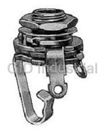
Conn 1/4" Phone Jack F 2 POS Solder Lug ST Panel Mount 2 Terminal 1 Port
11
Part Number
11
Price
Request Quote
Manufacturer
SWITCHCRAFT
Lead Time
Request Quote
Category
Connectors » Connector Audio and Video
Specifications
Manufacturer
Switchcraft
Manufacturers Part #
11
Industry Aliases
11
Sub-Category
Audio and Video Connectors
Factory Pack Quantity
100
Datasheet

Extracted Text
Pro Audio & Broadcast Catalog Sixth Edition w w w . s w i t c h c r a f t . c o m Patchbays, Patchcords & Connectors and Adapters Jacks and Plugs Guitar Switches Molded Cable Assemblies * Please visit the product pages on our website for the most up-to-date product information 1 About Switchcraft, Inc. Switchcraft, Inc. was established in 1946 to manufacture jacks, plugs, and switches. We Patchbay Series 4 – 43 have since become the industry leader in producing a wide variety of connectors, adapters, jacks and plugs, patchbays, jackfields, and switches. While our products cover a diverse number of markets, this catalog focuses on our line of audio and video products, typically found Patchcords/Molded Cables 44 – 45 in broadcast, recording, sound reinforcement, and other pro audio applications. Some of the new products you’ll find in this catalog include our EZ Norm Series of audio patchbays, where normal configurations can be changed from the front of the patchbay, using a Connector Series 46 – 62 standard screwdriver. Also found in this edition are new combination audio/video patchbays in both standard/long-frame and midsize/bantam styles. In the connector section, we’re offering a new line of connectors called our EH Series, incorporating a wide range of connectors (Firewire, Audio Adapter Series 63 – 64 USB, Category 6, BNC, RCA, and more) in a standard XLR housing. Please keep in mind that this is just a small sampling of our complete product lines. For more detailed information, we offer our “full line” catalog, our Engineering Design Guide. Jack Series 65 – 82 Our Engineering Design Guide includes over 5,000 part numbers covering all five major product lines. If you don't see it here, chances are you'll find it in the EDG. And again, keep in mind that the EDG is also just a "snapshot" of Plug Series 83 – 93 our capabilities. We manufacture over 30,000 part numbers, so if it's not in the EDG, please contact us with your requirements. To keep up on all the new products we have to offer, visit our website at www.switchcraft.com and look for the New Product Showcase. Switch Series 94 – 96 Index 98 – 100 Detailed Table of Contents — Pages 2 – 3 * Please visit the product pages on our website for the most up-to-date product information Table of Contents 2 Patchbays Connectors Professional Punchdown Terminal (PPT) ....................4 Q-G® Audio Connector Series..............................46-48 Audio Patchbay Series ............................................5–33 A, AA, AAA Cord Style Series ................................46 MTPH/TTPH Harness Series ..................................5-7 B, C, D, E Panel Style Series....................................47 Front Access Series ................................................8–9 J, K, P, R, T Wallplate, Gooseneck, Panel & Cord Style Series........................................48 EZ Norm Patchbay Series..................................10–11 Tini-Q-G® Connector Series ......................................49 RS 422 Data Patchbay Series ............................12–13 Tini-Q-G® Cord & Panel Style Series ....................49 MTP48K Wired Series ........................................14–15 HPC Connector Series............................................50-51 TTPW96K Wired Series......................................16–17 MTPBP/TTPBP Backpanel Series ......................18–19 HPC Panel Style Series ............................................50 TT96 EDAC Series ..............................................20–21 HPC Cord, & Adapter Style Series..........................51 TTP96K Patchkit Series ......................................22–23 EH Series Receptacles ................................................52 MT48K/MT52K Patchkit Series ..........................24–25 MIDI and 2500 Series ..................................................53 MT48/MT52 Patchbay Series ............................26–27 HP75BNC Series ..........................................................54 TTP96AS Patchbay Series..................................28–29 Connector Dimension Drawings ..........................55–62 HPC Patchbay Series ..........................................30–31 HP75BNC Series, EH Series ....................................55 ® Q-G Patchbay Series ........................................32–33 Q-G Audio - A, AA, AAA Series ..............................56 Video/Audio Patchbay Series................................34–44 Q-G Audio - B, C, D, E Series ..................................57 VPP Video Patchbay Series................................34–36 Q-G Audio - J, K, P, R Series....................................58 MVP Midsize Video Patchbay Series................37–39 Q-G Audio - T Series ................................................59 VAP Video/Audio Patchbay Series ....................40–41 MIDI, Q-G Audio - P Series......................................60 MVEZN Audio/Midsize Patchbay Series....................42 HPC Panel Style Series ......................................61–62 MBPK Video/Audio Patchbay Series ......................43 Audio Adapters Audio and Video Patchcords ................................44–45 XLR to XLR, RCA, 1/4", TQ-G Adapter Series ..........63 1/4" to 1/4", RCA; RCA to RCA; & Miscellaneous Adapter Series................................64 * Please visit the product pages on our website for the most up-to-date product information Table of Contents 3 3 3 Jacks & Plugs Jack Series Littel Phone, Hi-D, Right Angle PC Mount 1/4", 1/4" Littel Right Angle 1/4”, Silent, Super Extension Jack Series ..............................................65 Heavy Duty Plug Series ..........................................89 Thick Panel/Guitar, Locking 1/4", Tini, Tini- Tini, Micro Plug Series ............................................90 Extension, Micro, 3.5mm ........................................67 35HD 3.5mm Stereo Plug Series ............................91 Phono, Phono Extension, TT or Bantam, MT 1/4” Phono and Phone Right Angle Plug Series ..........92 Jack Series ................................................................69 TT or Bantam, Mil-Style 1/4” Plug Series ............93 Power/Jacks Plugs Series – 700, S700, 800 Cord & Panel Style Series ................................71 Switches Jack Series Dimension Drawings ........................72–82 Switch Series..........................................................94–95 Littel Phone, Hi-D, 1/4” Extension, 700 Panel Jack Switch Series Dimension Drawings ..........................96 Series ........................................................................72 Littel Phone, Hi-D, 1/4” Extension Jack Series......73 Right Angle PC Mount 1/4” Jack Series ................74 Thick Panel/Guitar, Locking 1/4”, Tini, Tini Extension Jack Series ..............................................75 Micro, 3.5mm Jack Series ......................................76 3.5mm Jack Series..............................................77–79 Phono and Phono Extension Jack Series ..............80 TT or Bantam Jack Series........................................81 MT 1/4” Jack Series..................................................82 Limited Lifetime Warranty Switchcraft warrants all of its products to be of sound design, good materials and workmanship at the time of Plug Series manufacture. Littel 1/4”, Right Angle 1/4”, Silent, Super Heavy Switchcraft will repair or replace at its discretion any Duty Plug Series ......................................................83 product proven to be defective under normal use. Switchcraft’s liability under the terms of this warranty Tini, Micro, 3.5mm Stereo, Right Angle 3.5mm is limited to the repair or replacement of defective products Stereo, Phono, Right Angle Phono Plugs Series ..85 which have not been damaged through accident, abuse, misuse or unauthorized repair. Switchcraft shall in no TT or Bantam, Mil-Style 1/4” Plugs Series ............87 case be liable for special or consequential damages of Plug Series Dimension Drawings ........................88–93 any nature. Littel Plug 1/4” Series ..............................................88 5555 North Elston Avenue / Chicago, IL 60630 Phone: 773-792-2700 / Fax: 773-792-2129 w w w . s w i t c h c r a f t . c o m * Please visit the product pages on our website for the most up-to-date product information PATCHBAYS Our Patchbays Now Feature the New 4 Professional Punchdown Terminal (PPT) Our Patchbays Have Just Rounded A New Corner Actually, the corners we rounded belong to our patchbays’ revolutionary, new Professional Punchdown Terminal (PPT), making it perfectly compatible with the industry standard. We realized that achieving a new industry standard meant we couldn’t cut any corners to get there. The PPT design incorporates a split-barrel design and a more rugged, thicker housing to minimize the impact of repeated punchdowns. The split-barrel design eliminates the problems associated with the old “V-shaped” terminal designs. The PPT design distributes pressure evenly across both sides of the terminated wire, causing improved wire retention plus more reliable connections. The serrated teeth in the plastic housing firmly grip the wires, which also greatly improves wire retention. With the PPT, multiple wires can be terminated to a single contact, and a wide range of wire gauges can be used. Look for Switchcraft’s PPT in our MTP and TTP Series of audio patchbays, and in our new Backpanel Series. All Switchcraft audio patchbays incorporate heavy gauge materials and our high quality nickel-plated, steel framed jacks. Gold-plated, crossbar contacts come standard! Materials Housing: Thermoplastic (UL 94V-0) Contacts: High strength copper alloy, tin plated Wire size: Accommodates #22, 24, or 26 AWG, stranded or solid Accessories Part Number Description K459 PPT replacement kit consists of 15 of each color* (IDC/IDC) K460 PPT replacement kit consists of 15 of each color (IDC/wirewrap) PT1LA PPT impact punchdown tool PT2B Replacement bit for PT1LA tool *Colors consist of red, black, white, yellow, blue, and orange. * Please visit the product pages on our website for the most up-to-date product information AES / EBU Digital Ready! PATCHBAYS DIGITAL MTPH/TTPH Harness Series 5 Features and Benefits • Units feature either 48 MT style jacks or 96 TT style jacks on the front panels, to a 4 foot harness, out to a backpanel with PPT’s MTPH48K3NO • All versions utilize AES/EBU wiring for complete digital compatibility • Attractive, corrosion resistant nickel-plated, steel frame jacks • Gold-plated switching contacts reduce contact resistance, improve reliability Specifications Materials Jacks Frame: Nickel-plated steel Bushing: Nickel-plated brass Tip, Ring and Shunt Springs: Nickel silver with welded contacts The MTPH and TTPH Harness Series utilize standard front panel assemblies, a Assembly Screws: Zinc-plated 4-foot cable harness, and our standard back panel assemblies. Primarily used steel where the back panels must either be mounted into a rack, or brought back to the Welded Contacts: Gold alloy front for easier access. Custom cable lengths can also be supplied. Contact the Panel factory for details. Front Channel: Black anodized aluminum Frame: C.R.S. black epoxy painted Ordering Information Designation Strips: Black Type No. of polycarbonate 94V-0 Part Number of Jack Jacks Description Designation Strip Covers: Clear MTPH48K1NS MT 48 1.75" High front panel, 4’ Harness, polycarbonate 3.5" High back panel, normals strapped Jack Inserts: Thermoplastic MTPH48K1NO MT 48 1.75" High front panel, 4’ Harness, polyester 3.5" High back panel, normals brought out MTPH48K3NS MT 48 3.5" High front panel, 4’ Harness, Mechanical 3.5" High back panel, normals strapped Life: 30,000 cycles MTPH48K3NO MT 48 3.5" High front panel, 4’ Harness, Insertion Force: 7 lbs. maximum 3.5" High back panel, normals brought out Withdrawal Force: 1 lb. minimum MTPH48K3SNO MT 48 3.5" High front panel, 4’ Harness, 3.5" High Environmental: 0˚C to +50˚C back panel, sleeve normals brought out Electrical TTPH96K1NS TT 96 1.75" High front panel, 4’ Harness, 3.5" High back panel, normals strapped Contact Resistance: 30 milliohms TTPH96K1NO TT 96 1.75" High front panel, 4’ Harness, maximum initial 5.25" High back panel, normals brought out Insulation Resistance: 10,000 TTPH96K3NS TT 96 3.5" High front panel, 4’ Harness, megohms maximum 3.5" High back panel, normals strapped Dielectric Withstanding Voltage: TTPH96K3NO TT 96 3.5" High front panel, 4’ Harness, 500 VAC at 60 Hz 5.25" High back panel, normals brought out Working Voltage: 140 VDC maximum Current Rating: 100 milliamps See Next Page for Mechanical Drawings 5555 North Elston Avenue / Chicago, IL 60630 Phone: 773-792-2700 / Fax: 773-792-2129 w w w . s w i t c h c r a f t . c o m * Please visit the product pages on our website for the most up-to-date product information PATCHBAYS MTPH/TTPH Harness Series 6 * Please visit the product pages on our website for the most up-to-date product information PATCHBAYS MTPH/TTPH Harness Series 7 Inch DIMENSIONS ARE FOR REFERENCE ONLY (mm) 5555 North Elston Avenue / Chicago, IL 60630 Phone: 773-792-2700 / Fax: 773-792-2129 w w w . s w i t c h c r a f t . c o m * Please visit the product pages on our website for the most up-to-date product information PATCHBAYS Front Access Series 8 Features and Benefits • Easy slide-out tray slides forward for easy re-termination from the front of the rack • Available with either 48 MT style or 96 TT style jacks in a 1RU space • Attractive, corrosion resistant nickel-plated, steel frame jacks • Gold-plated switching contacts reduce contact resistance, improves reliability • Extra wide designation strips for easy channel identification • Rugged, attractive black epoxy-finished steel chassis TTPFA96K1NS • Configurations available include normals strapped and normals brought out Specifications Materials The Front Access Series offers the end user the ease of re-terminating patchpoints from the front of the rack as opposed to the back. A slide out tray allows the user Jacks to slide out the punchdown terminals and reconfigure the unit. An easy release Frame: Nickel-plated steel mechanism on either side of the unit allows it to be pushed back into place and Bushing: Nickel-plated brass easy to grip locking nuts tighten the unit in place. Tip, Ring and Shunt Springs: Nickel silver with welded contacts Assembly Screws: Nickel-plated Electrical steel Jack Contact Resistance: Dielectric Withstanding Voltage: Welded Contacts: Gold alloy 30 milliohms initial maximum; 500V at 60 Hz AC Panel 50 milliohms after life Working Voltage: 100 milliamps or Frame: C.R.S. black epoxy Jack Insulation Resistance: less; maximum 56.5 VDC painted 10,000 megohms maximum Designation Strips: Black polycarbonate 94V-0 Designation Strip Covers: Clear polycarbonate Ordering Information Jack Inserts: Thermoplastic 94V-0 Part Number Type of Jack No. of Jacks Description Mechanical TTPFA96K1NS TT 96 1.75" High, normals strapped Life: 30,000 cycles Insertion Force: 7 lbs. maximum TTPFA96K1NO TT 96 1.75" High, normals brought out Withdrawal Force: 1 lb. minimum MTPFA48K1NS MT 48 1.75" High, normals strapped Operating: -20˚C to +65˚C MTPFA48K1NO MT 48 1.75" High, normals brought out * Please visit the product pages on our website for the most up-to-date product information PATCHBAYS Front Access Series 9 Inch DIMENSIONS ARE FOR REFERENCE ONLY (mm) 5555 North Elston Avenue / Chicago, IL 60630 Phone: 773-792-2700 / Fax: 773-792-2129 w w w . s w i t c h c r a f t . c o m * Please visit the product pages on our website for the most up-to-date product information PATCHBAYS EZ Norm Patchbay Series 10 TTEZN****0 Center Strip Removes For Normalling Access The EZ Norm offers a simplified method for setting up and changing normals to a Bantam/TT patchbay. Simply remove the middle designation strip, and rotate the center cam, using a standard screwdriver. An audible “click” can be heard as you rotate from full normals to no normals to half normals. An opaque marking strip is included to conceal the normal position, if needed. Easily Normal The Jacks By Rotating To “Full”, “Non,” Or “Half” Positions Specifications Materials Electrical Jack Spring Contact Resistance: 30 milliohm Jacks Maximum Housing & Cover: 94V-0 rated thermoplastic Cam Switch Contact Resistance: 30 milliohm Sleeve Collar: Nickel plated copper alloy Maximum Tip, Ring, Shunt, & Sleeve Springs: Nickel Silver Insulation Resistance: 10,000 Megaohms with welded contacts Dielectric Withstanding Voltage: Welded Contacts: Gold 500 VAC (rms) at 60 Hz Cam Switching Springs: Silver plated copper alloy Insertion Loss: -0.5dB up to 10 MHz Cam Switching Contacts: Silver plated copper alloy EZ Norm Patchbay Options Mechanical • 1RU can be terminated to EDAC or Cannon DL, Jack Mechanical Life: 30,000 cycles solder terminals, or wire-wrap terminals Cam Contact Mechanical Life: 30,000 cycles Insertion - Withdrawal Forces: 1 - 4 lbs. • 1.5RU can be terminated to EDAC/Cannon DL, Moisture resistance: MIL-STD 202 Method 106 solder terminals, wire-wrap terminals, plus 3 pin Thermal shock: MIL-STD 202 Method 107 connectors, or our own PPT Professional Salt spray: MIL-STD Method 101 (48 hrs.) Punchdown Terminal Vibration: MIL-STD 202 Method 213 • 2RU Same as above • All units will be offered with or w/o docking connector • Unwired units will be offered with either cable tie bar or cable tray * Please visit the product pages on our website for the most up-to-date product information PATCHBAYS EZ Norm Patchbay Series 11 Racks The EZ Norm comes in 3 different rack heights, 1RU, 1.5RU, and 2 RU. Harness Assembly The EZ Norm is also offered as a harness assembly, with a standard harness of 4 ft. Custom lengths are ® TT EZN _ 10 _ _ E90 IDC SL _ available, call Switchcraft for details. H 15 P D E56 3PIN CDL T 20 E38 WW FA B Front Access The Front Access option offers a slide-out tray, allowing the end user to re-terminate the patch- bay from the front of the rack. Inch DIMENSIONS ARE FOR REFERENCE ONLY (mm) 5555 North Elston Avenue / Chicago, IL 60630 Phone: 773-792-2700 / Fax: 773-792-2129 w w w . s w i t c h c r a f t . c o m TT TT SIZE JACKS EZN EZ-NORM CAM JACKS _ REGULAR UNIT H HARNESS UNIT (UMBILICAL) } 10 1 RACK UNIT HEIGHT 15 1.5 RACK UNIT HEIGHT } 20 2 RACK UNIT HEIGHT _ UNWIRED } P PRE WIRED _ NO DOCKING } D DOCKING CONNECTOR E90 EDAC/ELCO 90 PIN CONNECTOR E56 EDAC/ELCO 56 PIN CONNECTOR E38 EDAC/ELCO 38 PIN CONNECTOR IDC IDC PPT TERMINALS 3PIN 3 PIN CONNECTORS WW WIRE WRAP PINS SL SOLDER LUGS } CDL CANNON DL 96 PIN CONNECTORS FA FRONT ACCESS WITH PPT _ NO REAR SUPPORT UNWIRED ONLY T CABLE TRAY } B CABLE BAR * Please visit the product pages on our website for the most up-to-date product information PATCHBAYS RS 422 Data Patchbay Series 12 Our standard RS data jackfield series offer a multiple combination of ports, rack heights, and back panel terminations which will easily fit into any television broadcast or video production where custom data patching is required. Custom ports and rack height combinations can be supplied. Contact the factory for details. Ordering Information Features and Benefits • Unit Features either 8,16, 24, or 32 TT style Part No. of Front Panel Back Rack Number* Jacks Layout Plane Height jacks on the front Panels, to a 9 pin D-Sub. RS422H4N081 2 x 8 Horizontal 9 Pin D-Sub 1 • All versions utilize low capacitance internal RS422V4N081 2 x 8 Vertical 9 Pin D-Sub 1 wiring for maximum performance of RS422H4N161 2 x 16 Horizontal 9 Pin D-Sub 1 transferring data RS422H4N162 2 x 16 Horizontal 9 Pin D-Sub 2 • All standard units are available 1 or 2 rack RS422V4N161 2 x 16 Vertical 9 Pin D-Sub 1 units high (1.5 RU available by request) RS422V4N162 2 x 16 Vertical 9 Pin D-Sub 2 • Rugged, attractive black epoxy finished RS422H4N242 2 x 24 Horizontal 9 Pin D-Sub 2 steel frame chassis RS422V4N242 2 x 24 Vertical 9 Pin D-Sub 2 RS422V4N322 2 x 32 Vertical 9 Pin D-Sub 2 Specifications *Add “N” for non-normalled version Electrical Internal Wiring: 24 AWG Solid TC, foils shield Nom Capacitance: 11.5 pF/ft between conductors 21.3 pF/ft between one conductor and conductor connected to the shield Nom. Impedence: 110 Ohms * Please visit the product pages on our website for the most up-to-date product information PATCHBAYS RS 422 Data Patchbay Series 13 RS422V4N322 32 Vertical Paired Jacks Front and Back Views RS422H4N242 24 Horizontal Paired Jacks Front and Back Views Inch DIMENSIONS ARE FOR REFERENCE ONLY (mm) 5555 North Elston Avenue / Chicago, IL 60630 Phone: 773-792-2700 / Fax: 773-792-2129 w w w . s w i t c h c r a f t . c o m * Please visit the product pages on our website for the most up-to-date product information AES / EBU Digital Ready! PATCHBAYS DIGITAL MTP48K Wired Series 14 Features and Benefits • Unit features 48 MT style jacks in either 1RU (1.75" H) or 2RU (3.5" H) spaces • All versions utilize AES/EBU wiring for complete digital compatibility • Attractive, corrosion resistant nickel-plated, steel frame jacks • Gold-plated switching contacts reduce contact resistance, improve reliability • Rugged, attractive black epoxy- finished steel chassis MTP48K3NO • Extra wide designation strips for easy channel identification • 1RU version configurations include normals strapped and normals brought out • 2RU version configurations include normals strapped, normals brought out, and sleeve normals brought out The MTP Series was developed with the AES/EBU digital standard in mind. All versions are made with 110 Ohm cabling inside as a standard. Available in Specifications a wide variety of configurations. Materials Jacks Mechanical Frame: Nickel-plated steel Bushing: Nickel-plated brass Life: 30,000 cycles Insulation Resistance: 10,000 Tip, Ring and Shunt Springs: Insertion Force: 7 lbs. maximum megohms maximum Nickel silver with welded Withdrawal Force: 1 lb. minimum Dielectric Withstanding Voltage: contacts Environmental: O˚C to +50˚C 500 VAC at 60 Hz Assembly Screws: Zinc-plated Working Voltage: 140 VDC Electrical steel maximum Contact Resistance: 30 milliohms Welded Contacts: Gold alloy Current Rating: 100 milliamps maximum initial Panel Front Channel: Black anodized aluminum Ordering Information Frame: C.R.S. black epoxy painted Part Number Type of Jack No. of Jacks Description Designation Strips: Black polycarbonate 94V-0 MTP48K1NS MT 48 1.75" High, normals strapped Designation Strip Covers: Clear MTP48K3NS MT 48 3.5" High, normals strapped polycarbonate MTP48K1NO MT 48 1.75" High, normals brought out Jack Inserts: Thermoplastic MTP48K3NO MT 48 3.5" High, normals brought out polyester MTP48K3SNO MT 48 3.5" High, sleeve normals out * Please visit the product pages on our website for the most up-to-date product information PATCHBAYS MTP48K Wired Series 15 Inch DIMENSIONS ARE FOR REFERENCE ONLY (mm) 5555 North Elston Avenue / Chicago, IL 60630 Phone: 773-792-2700 / Fax: 773-792-2129 w w w . s w i t c h c r a f t . c o m * Please visit the product pages on our website for the most up-to-date product information AES / EBU Digital Ready! PATCHBAYS DIGITAL TTPW96K Wired Series 16 Features and Benefits • Unit features 96 TT style jacks in 2RU (3.5"H) space • Utilizes AES/EBU wiring for complete digital compatibility • Attractive, corrosion resistant nickel-plated, steel frame jacks • Gold-plated switching contacts reduce contact resistance, improve reliability • Rugged, attractive black epoxy- finished steel chassis TTPW96K3NS • Extra wide designation strips for easy channel identification Specifications Materials Jacks Frame: Nickel-plated steel Bushing: Nickel-plated brass Tip, Ring and Shunt Springs: Nickel silver with welded contacts The TTPW96K Series was developed with the AES/EBU digital standard in mind. Assembly Screws: Zinc-plated As a standard, the TTPW96K utilizes 110 Ohm cabling inside. steel Welded Contacts: Gold alloy Panel Electrical Front Channel: Contact Resistance: 30 milliohms Black anodized aluminum maximum initial Frame: C.R.S. black epoxy painted Insulation Resistance: 10,000 Designation Strips: Black megohms maximum polycarbonate 94V-0 Dielectric Withstanding Voltage: Designation Strip Covers: Clear 500 VAC at 60 Hz polycarbonate Working Voltage: 140 VDC Jack Inserts: Thermoplastic maximum polyester Current Rating: 100 milliamps Mechanical Ordering Information Life: 30,000 cycles Part Number Type of Jack No. of Jacks Description Insertion Force: 7 lbs. maximum Withdrawal Force: 1 lb. minimum TTPW96K1NN TT 96 1.75" High, non-normals Environmental: 0˚C to +50˚C TTPW96K1HN TT 96 1.75" High, half normals TTPW96K1NS TT 96 1.75" High, normals strapped TTPW96K3NN TT 96 3.5" High, non-normals TTPW96K3HN TT 96 3.5" High, half normals TTPW96K3NS TT 96 3.5" High, normals strapped * Please visit the product pages on our website for the most up-to-date product information PATCHBAYS TTPW96K Wired Series 17 Inch DIMENSIONS ARE FOR REFERENCE ONLY (mm) 5555 North Elston Avenue / Chicago, IL 60630 Phone: 773-792-2700 / Fax: 773-792-2129 w w w . s w i t c h c r a f t . c o m * Please visit the product pages on our website for the most up-to-date product information PATCHBAYS MTPBP/TTPBP Backpanel Series 18 Features and Benefits • Allows for custom patchbay configurations or central patching points • PPTs have IDCs on both sides for easy installation MTP48K3BPNS • Rugged, attractive black epoxy-finished steel chassis • Cable trays allow for mounting and securing terminated cable Specifications Panel thickness: .093" Mounting hole diameter: .187" Mounting hole spacing (48 IDCs/row): .340" (Horizontal) x .275" (Vertical) Mounting hole spacing (52 IDCs/row): .320" (Horizontal) x .275" (Vertical) Wire size: #22, 24, 26 AWG Stranded or Solid The Backpanel Series offers the end user the flexibility of configuring their own (IDC termination) patchbay, or to use as a central patchpoint location. The backpanels utilize the Materials PPT punchdown and come with a rugged cable tray. Housing: Thermoplastic (UL 94V-0) Contacts: High strength copper alloy Backpanels: Black Epoxy coated C.R.S. Ordering Information Cable Tray: Black Epoxy coated Sets of C.R.S. Part Number PPT Terminals Height Description MTP48K3BPNS 48 3.5" T, R, S MTP48K3PBNO 48 3.5" T, R, S, TN, RN MTP52K3BPNO 52 3.5" T, R, S, TN, RN MTP24K7 24 x 2 7.0" +, -, S TTP96K3BPNS 96 3.5" T, R, S TTP96K5BPNS 96 x 2 5.25" T, R, S, TN, RN * Please visit the product pages on our website for the most up-to-date product information PATCHBAYS MTPBP/TTPBP Backpanel Series 19 Inch DIMENSIONS ARE FOR REFERENCE ONLY (mm) 5555 North Elston Avenue / Chicago, IL 60630 Phone: 773-792-2700 / Fax: 773-792-2129 w w w . s w i t c h c r a f t . c o m * Please visit the product pages on our website for the most up-to-date product information PATCHBAYS TT96 EDAC Series 20 Features and Benefits • Attractive, corrosion-resistant, nickel-plated jacks • Steel frame jacks for superior jack life • Extra wide labeling strips provide maximum space and two vertical strips, one at each side • Rugged, attractive black anodized aluminum face will not break • Two configurations available: - Normals brought out - Normaled at jacks • Gold switching contacts for TT96EDACNS long-term reliability • Jacks paired for easy identification of left and right channels ® • Connectorized by EDAC connectors for ease of termination by customer Specifications ® The TT96EDAC Series offers the convenience of EDAC connectors on the back of Materials the panel for easy installation. Available in normals strapped and normals brought out, both wired to the SAC code of wiring. We also offer custom wiring Jacks configurations. Contact the factory for details. Frame: Nickel-plated steel Bushing: Nickel-plated brass Tip, Ring and Shunt Springs: Nickel Electrical EDAC Mating Plugs silver with welded contacts Contact Resistance: 30 milliohms Part Number Description Assembly Screws: Zinc-plated maximum initial 516-090-000-301 90 Pin male w/ screw steel Insulation Resistance: Welded Contacts: Gold alloy 516-090-000-302 90 Pin male w/ nut 10,000 megohms Panel 516-120-000-101 120 Pin male w/ screw Dielectric Withstanding Voltage: Front Channel: Black anodized 516-120-000-102 120 Pin male w/ nut 500VAC at 60 Hz aluminum Working Voltage: 140VDC 516-290-500 Terminal solder-style Frame & Cover: C.R.S. black Current Rating: 100 milliamps 516-290-590 Terminal crimp-style epoxy painted Designation Strips: Black polycar- bonate 94V-0 Designation Strip Covers: Clear Ordering Information polycarbonate Part Number Type of Jack No. of Jacks Description Jack Inserts: Polyester TT96EDACNO TT 96 Normals Brought Out (120 pin EDAC) EDAC Connector Housing: Thermoplastic, UL94V-0 TT96EDACNS TT 96 Normals Strapped (90 pin EDAC) Contacts: Gold plated phosphor bronze Mechanical Life: 30,000 cycles Insertion Force: 7 lbs. maximum Withdrawal Force: 1 lb. minimum Operating: -20˚C to +65˚C * Please visit the product pages on our website for the most up-to-date product information PATCHBAYS TT96 EDAC Series 21 JACK #1 FOR INPUT AND OUTPUT #1 THROUGH #24, AND JACK #25 FOR INPUT AND OUTPUT #25 THROUGH #48 JACK #2 FOR INPUT AND OUTPUT #1 THROUGH #24, AND JACK #26 FOR INPUT AND OUTPUT #25 THROUGH #48 Standard Audio Configuration Wiring (S.A.C.) Standard Audio Configuration Wiring (S.A.C.) 90 Pin Plug Connector 120 Pin Plug Connector (Normals at jacks) (Normals brought out) Inch DIMENSIONS ARE FOR REFERENCE ONLY (mm) 5555 North Elston Avenue / Chicago, IL 60630 Phone: 773-792-2700 / Fax: 773-792-2129 w w w . s w i t c h c r a f t . c o m * Please visit the product pages on our website for the most up-to-date product information PATCHBAYS TTP96K Patchkit Series 22 Features and Benefits • Kit features 96 TT jacks in one rack space (1.75" high) or two rack spaces (3.5" high) • Jack blocks can be removed from the front for easy soldering • Dust tray limits dirt, dust and contamination of jack terminals • Wire management straps are adjustable and reusable TTP96K1FN • Attractive, corrosion resistant nickel-plated jacks • Steel frame jack for superior jack life • Extra wide labeling strips provide maximum space • Rugged, attractive black anodized aluminum face will not break The TTP96K Patchkit Series offers the end user a rugged cable tray to support or rust rear cabling. Heavy duty construction takes weight off the back of the jacks for • Three jack configurations available increased reliability. Available in 1.75" or 3.5" height versions. for the exact switching arrangement you need: full normal, half normal, and non-normal (open circuit) • Fanned solder terminals for easier solder connections Mechanical Electrical • Gold switching contacts for long- Life: 30,000 cycles Contact Resistance: 30 milliohms term reliability in normal-through Insertion Force: 7 lbs. maximum maximum initial connections Withdrawal Force: 1 lb. minimum Insulation Resistance: Environmental: 0˚C to +50˚C 10,000 megohms maximum Specifications Dielectric Withstanding Voltage: Materials 500VAC at 60 Hz Working Voltage: 140VDC maximum Jacks Current Rating: 100 milliamps Frame: Nickel-plated steel Bushing: Nickel-plated brass Tip, Ring and Shunt Springs: Ordering Information Nickel silver with welded contacts Part Number Type of Jack No. of Jacks Description Assembly Screws: Nickel-plated TTP96K1FN TT 96 1.75" High, full normals steel TTP96K1HN TT 96 1.75" High, half normal Welded Contacts: Gold alloy TTP96K1NN TT 96 1.75" High, no normals Panel TTP96K3FN TT 96 3.5" High, full normals Front Channel: Black anodized aluminum TTP96K3HN TT 96 3.5" High, half normals Frame: C.R.S. black epoxy painted TTP96K3NN TT 96 3.5" High, no normals Designation Strips: Black polycarbonate 94V-0 Designation Strip Covers: Clear polycarbonate Jack Inserts: Thermoplastic polyester * Please visit the product pages on our website for the most up-to-date product information PATCHBAYS TTP96K Patchkit Series 23 Inch DIMENSIONS ARE FOR REFERENCE ONLY (mm) 5555 North Elston Avenue / Chicago, IL 60630 Phone: 773-792-2700 / Fax: 773-792-2129 w w w . s w i t c h c r a f t . c o m * Please visit the product pages on our website for the most up-to-date product information PATCHBAYS MT48K/MT52K Patchkit Series 24 Features and Benefits • Kit features 48 1/4" longframe jacks in one rack space (1" high) or in two rack spaces (3" high) or 52 1/4" longframe jacks in one rack space (1" high) • Allows user to add cable and termination panel • Removable jack panel from the front allows easy soldering of wire connections MT52K1FN • Jacks have gold switching contacts • Fanned solder terminals for easier soldering • Offset ground lugs allow easy bussing of ground with one wire • Jacks have a nickel-plated frame and assembly screws The MT48/52K Patchkit Series offers the end user a rugged cable tray to support • Wire management straps are rear cabling. Heavy duty construction takes weight off the back of the jacks for reusable and adjustable increased reliability. Available in 1.75" or 3.5" height versions. Specifications Electrical Dielectric Withstanding Voltage: 500VAC at 60 Hz Contact Resistance: 30 milliohms Materials Working Voltage: 140VDC maximum initial Jacks maximum Insulation Resistance: 10,000 Frame: Stamped nickel-plated Current Rating: 100 milliamps megohms maximum steel Bushing: Nickel-plated brass Ordering Information Tip, Ring and Shunt Springs: Part Number Type of Jack No. of Jacks Height Description Nickel silver with welded contacts MT48K1NS MT 48 1.75" Normals strapped Assembly Screws: Nickel-plated MT48K1FN MT 48 1.75" Full normals steel MT48K1HN MT 48 1.75" Half normals Welded Contacts: Gold alloy MT48K1NN MT 48 1.75" No normals Panel MT52K1NS MT 52 1.75" Normals strapped Front Panel: Thermoplastic MT52K1FN MT 52 1.75" Full normals Frame: C.R.S. black epoxy paint Designation Strips: Black MT52K1HN MT 52 1.75" Half normals polycarbonate 94V-0 MT52K1NN MT 52 1.75" No normals Designation Strip Covers: Clear MT48K3FN MT 48 3.5" Full normals polycarbonate MT48K3HN MT 48 3.5" Half normals Mechanical MT48K3NN MT 48 3.5" No normals Life: 30,000 cycles MT52K3FN MT 52 3.5" Full normals Insertion Force: 7 lbs. maximum MT52K3HN MT 52 3.5" Half normals Withdrawal Force: 1 lb. minimum Operating: 0˚C to +50˚C MT52K3NN MT 52 3.5" No normals * Please visit the product pages on our website for the most up-to-date product information PATCHBAYS MT48K/MT52K Patchkit Series 25 Inch DIMENSIONS ARE FOR REFERENCE ONLY (mm) 5555 North Elston Avenue / Chicago, IL 60630 Phone: 773-792-2700 / Fax: 773-792-2129 w w w . s w i t c h c r a f t . c o m * Please visit the product pages on our website for the most up-to-date product information PATCHBAYS MT48/MT52 Patchbay Series 26 Features and Benefits • Units feature either 48 or 52 ® MT Jax • Steel frame jacks for superior jack life • Attractive, corrosion resistant nickel-plated jacks • Gold switching contacts for MT48FN long-term reliability in normal- through connections • Offset ground terminal for ease in making common ground buss connections • Fanned solder terminals for easier solder connections • Cable tie bar takes the weight of cables off the jacks • Four jack configurations available for the exact switching arrangement: full normal, half The MT48/52 Series patchbays offer a rugged cable tie bar to support rear normal, non-normal, and cabling. Also available is the normals strapped configuration which has the shunts normals strapped or normals tied together, top to bottom jacks. Specifications Mechanical Electrical Materials Life: 30,000 cycles Contact Resistance: 30 milliohms Jacks Insertion Force: 7 lbs. maximum maximum initial Frame: Steel, nickel-plated Withdrawal Force: 1 lb. minimum Insulation Resistance: 10,000 Bushing: Brass, nickel-plated Operating: 0˚C to +50˚C megohms maximum Springs: Nickel silver, solder lugs Dielectric Withstanding Voltage: Ground Terminal: Nickel silver, 500VAC at 60 Hz solder lugs Working Voltage: 140VDC Switching Contacts: Welded, maximum gold alloy Current Rating: 100 milliamps Insulation: Phenolic spacers, rigid PVC tubing through stack Ordering Information Screws: Steel, nickel-plated Part Number Type of Jack No. of Jacks Description Panel MT48FN MT 48 Full normals Jack Panel: Thermoplastic Cable Support Bracket: 5/16" MT48HN MT 48 Half normals diameter black epoxy painted MT48NN MT 48 No normals steel rod MT48NS MT 48 Normals strapped Screws (designation strip): Steel, MT52FN MT 52 Full normals black zinc-plated MT52HN MT 52 Half normals Screws (mounting jack): Steel, nickel plated MT52NN MT 52 No normals ® Kwik-change Designation Strip: MT52NS MT 52 Normals strapped Extruded aluminum, black anodized Marking Strip: White plastic, matte finish Marking Strip Cover: Clear, extruded plastic * Please visit the product pages on our website for the most up-to-date product information PATCHBAYS MT48/MT52 Patchbay Series 27 Inch DIMENSIONS ARE FOR REFERENCE ONLY (mm) 5555 North Elston Avenue / Chicago, IL 60630 Phone: 773-792-2700 / Fax: 773-792-2129 w w w . s w i t c h c r a f t . c o m * Please visit the product pages on our website for the most up-to-date product information PATCHBAYS TTP96AS Patchbay Series 28 Features and Benefits • Unit features 96 TT jacks • Attractive, corrosion resistant nickel-plated jacks • Steel frame jack for superior jack life • Extra wide labeling strips provide maximum space TTP96ASFN • Rugged cable tie bar takes the weight of cables off the jacks • Rugged, attractive black anodized aluminum face will not break • Three jack configurations available for the exact switching arrangement you need: full normal, half normal, and open circuit panel • Fanned solder terminals for easier solder connections • Offset ground terminal for ease in The TTP96AS Series of patchbays offer a rugged cable tie bar to support making common ground buss rear cabling. connections • Gold switching contacts for long-term reliability in normal- Designation Strip Covers: Clear Electrical through connections thermoplastic, SE-1 Contact Resistance: 30 milliohms Marking Strip: Rigid vinylite maximum initial Jack Mounting Screws: Steel, plated Insulation Resistance: 10,000 Specifications Screws: Steel, black plated megohms maximum Materials Dielectric Withstanding Voltage: Mechanical 500VAC at 60 Hz Jacks Life: 30,000 cycles Working Voltage: Frame: Steel, nickel-plated Insertion Force: 7 lbs. maximum 140VDC maximum Bushing: Nickel-plated copper alloy Withdrawal Force: 1 lb. minimum Current Rating: 100 milliamps Springs: Copper alloy solder lugs Environmental: 0˚C to +50˚C Ground Terminal: Steel, tin electrodeposited Switching Contacts: Welded, gold alloy inlay over palladium base Insulation: Rigid plastic spacers, rigid PVC tubing through stack Ordering Information Screws: Steel, plated Part Number Type of Jack No. of Jacks Description Panel Frame: Black anodized aluminum TTP96ASFN TT 96 Full normals Inserts: Polyester, glass filled, TTP96ASHN TT 96 Half normals 94V-0 TTP96ASNN TT 96 No normals Cable Support Bar: Cold rolled steel, nickel-plated Designation Strips: Thermoplastic, 94V-0 * Please visit the product pages on our website for the most up-to-date product information PATCHBAYS TTP96AS Patchbay Series 29 Inch DIMENSIONS ARE FOR REFERENCE ONLY (mm) 5555 North Elston Avenue / Chicago, IL 60630 Phone: 773-792-2700 / Fax: 773-792-2129 w w w . s w i t c h c r a f t . c o m * Please visit the product pages on our website for the most up-to-date product information PATCHBAYS HPC Patchbay Series 30 Features and Benefits • Available in 1RU or 2RU versions • Available with or without connectors • HPC Series connectors are ® compatible with Neutrik Speakon connectors • Cable tie bar takes weight of the cables off the terminations • Rugged aluminum channel • Silk-screen designation area makes it easy to re-label channels Panel Materials HPCPK324F Housing: Thermoplastic UL 94V-0 rated Contacts: Silver-plated over copper alloy Frame: Aluminum, black anodized Cable Tie Bar: Steel, black epoxy The HPC Patchbay features a 19" rack unit loaded with HPC Series connectors. ® ® HP Connector Specifications Available with either 0.250" Faston terminals or 0.187" Faston terminals. One rack unit height versions come with 12 HPC connectors, two rack unit height Mechanical versions come with 24 HPC connectors. All versions have a rugged cable tie bar, Shock: Per Mil-Std 202, which takes the weight of the cabling away from the connections. Method 213B, Cond. K Vibration: Mil-Std 202, Materials Method 201A Life: 1,000 rotational cycles Housings: Thermoplastic Cable Range (cord mount): 10AWG, UL 94V-0 rated 0.560" cable OD maximum Seal Rings: Thermoplastic rubber Contacts: Silver-plated over copper alloy Electrical Voltage Rating: 1,500 AC RMS, per Mil-Std 202, Method 301 Current Rating (Faston® terminals): 50A RMS w/10AWG wire, Ordering Information normal ambient, per UL 1977 Part Number Height Description Current Rating (PC terminals): HPCPK112F 1.75" 12 connectors, 0.250" Fastons 30A per UL 1977 Contact Resistance: 1m1, 1.5m1 HPCPK112F1 1.75" 12 connectors, 0.187" Fastons after 1,000 insertion/withdrawals HPCPK1B 1.75" Blank panel Insulation Resistance: .2T1 HPCPK324F 3.50" 24 connectors, 0.250" Fastons HPCPK324F1 3.50" 24 connectors, 0.187" Fastons Environmental HPCPK3B 3.50" Blank panel Salt Spray: Mil-Std 202, Method 101D, Cond.B Thermal Shock: Mil-Std 202, Method 107G Temperature Limits: -55˚C to +85˚C Moisture Resistance: Mil-Std 202, Method 106E Life @ Ambient Temperature: Mil-Std 202, Method 108A Touchproof: IEC 65 and 1010-1 IP Rating: IEC 529, IP 25 * Please visit the product pages on our website for the most up-to-date product information PATCHBAYS HPC Patchbay Series 31 Inch DIMENSIONS ARE FOR REFERENCE ONLY (mm) 5555 North Elston Avenue / Chicago, IL 60630 Phone: 773-792-2700 / Fax: 773-792-2129 w w w . s w i t c h c r a f t . c o m * Please visit the product pages on our website for the most up-to-date product information PATCHBAYS ® Q-G Patchbay Series 32 Features and Benefits • Available in 1RU or 2RU versions • Available with or without the connectors • E Series connectors are silver-plated, 3 pins/contacts with black finish • Cable tie bar takes the weight of the cables off the solder terminations • Rugged aluminum channel increases durability QGPK332MFB • Silk-screen designation area makes it easy to re-label channels Specifications Materials Connectors Housing: Die-cast, black velvet finish Inserts: Glass-filled thermoplastic Pin/Contacts: Copper alloy, ® ® silver-plated The QG Patchbay features a 19" rack unit loaded with E Series QG connectors. Latch Release: Steel, nickel-plated These XLR’s have the same panel cut-out, male or female, silver-plated pins or Insert Locking Cam: Die-cast zinc contacts, and a black finish. All connectors have solder cup terminals for easy soldering and the inserts are removable from the back, allowing for easy changes. Frame The one rack unit height version comes with 16 male, or 16 female, or 8 male Aluminum, black anodized and 8 female connectors. The two rack unit version comes with 16 male and 16 Cable Tie Bar female connectors. We also offer the unit without connectors, but with the panel Steel, black epoxy cut-outs already punched out. All versions have a rugged cable tie bar, which takes the weight of the cabling away from the solder connections. Ordering Information Part Number Height Description QGPK116FB 1.75" 16 female QGPK116MB 1.75" 16 male QGPK18M8FB 1.75" 8 male, 8 female QGPK332MFB 3.5" 16 female( top), 16 male (bottom) QGPK1B 1.75" Blank panel QGPK3B 3.5" Blank panel * Please visit the product pages on our website for the most up-to-date product information PATCHBAYS ® Q-G Patchbay Series 33 Inch DIMENSIONS ARE FOR REFERENCE ONLY (mm) 5555 North Elston Avenue / Chicago, IL 60630 Phone: 773-792-2700 / Fax: 773-792-2129 w w w . s w i t c h c r a f t . c o m * Please visit the product pages on our website for the most up-to-date product information PATCHBAYS VPP Video Patchbay Series 34 Features and Benefits • HD Series rated from DC to VPP24K3HD75T 3.0 GHz • SD Series has a bandwidth from DC to 1.75GHz • Black thermoplastic modules insulate jacks from chassis • Jacks feature rugged heavy duty housings VJHD*75TX Video Jack Specifications Electrical Rated Bandwidth: 3.0 GHz (HD), 1.75 GHz (SD) The VPP Series video patchbays offer a wide variety of options for video patching. Characteristic Impedance: The HD Series meets SMPTE 292M specifications for high definition video signaling, 75 ohms covering a bandwidth range from DC to 3.0GHz. The SD Series is perfect for serial Return Loss: Better than –15 dB digital, with a bandwidth from DC to 1.75GHz. Both come in either terminated or Insertion Loss: Better than –.5 dB non-terminated, 24 or 26 jacks, 1.75" or 3.5" heights. Contact Resistance: Less than 20 milliohms Termination Resistance: 75 W, ±1% Center Conductor: Accepts .090 Ordering Information pin diameter Part Number Type of Jack No. of Jacks Height Description Mechanical VPP24K1HD*75T HD 24 1.75" Terminated Mechanical Shock: Per MIL-STD- VPP24K1HD*NT HD 24 1.75" Non-term 202, Method 213, Test condition I VPP24K1SD*75T SD 24 1.75" Terminated Vibration: Per MIL-STD-202, VPP24K1SD*NT SD 24 1.75" Non-term Method 201 Life Cycle: 30,000 VPP26K1HD*75T HD 26 1.75" Terminated VPP26K1HD*NT HD 26 1.75" Non-term Materials VPP26K1SD*75T SD 26 1.75" Terminated Housing: Zinc alloy, nickel plated VPP26K1SD*NT SD 26 1.75" Non-term Center Contacts: Copper alloy, gold plated VPP24K3HD*75T HD 24 3.5" Terminated Switching Springs: Copper alloy, VPP24K3HD*NT HD 24 3.5" Non-term gold plated VPP24K3SD*75T SD 24 3.5" Terminated Grounding Contacts: VPP24K3SD*NT SD 24 3.5" Non-term HD Series - Copper alloy, gold VPP26K3HD*75T HD 26 3.5" Terminated plated VPP26K3HD*NT HD 26 3.5" Non-term SD Series - Copper alloy, nickel VPP26K3SD*75T SD 26 3.5" Terminated plated VPP26K3SD*NT SD 26 3.5" Non-term Insulators: Thermoplastic, UL 94V-0 rated * Add “N” for non-normalled version Environmental See Page 36 for Individual Jacks Ordering Information Operating Temperature: – 40°C to 65°C Storage Temperature: – 55°C to 85°C Thermal Shock: Per MIL-STD-202, Method 107 Moisture and Humidity: Per MIL-STD-202, Method 106 * Please visit the product pages on our website for the most up-to-date product information PATCHBAYS VPP Video Patchbay Series 35 Inch DIMENSIONS ARE FOR REFERENCE ONLY (mm) 5555 North Elston Avenue / Chicago, IL 60630 Phone: 773-792-2700 / Fax: 773-792-2129 w w w . s w i t c h c r a f t . c o m * Please visit the product pages on our website for the most up-to-date product information PATCHBAYS VPP Video Patchbay Series 36 (TYPICAL) SMITH CHART Ordering - Individual Jacks Part Number Type Description VJHD*75TX HD Terminated VJHD*NTX HD Non-terminated VJSD*75TX SD Terminated VJSD*NTX SD Non-terminated * Add “N” for non-normalled version 75 Ohms START 30 kHz STOP 3.0 GHZ (TYPICAL) RETURN LOSS INSERTION LOSS (TYPICAL) I 0 G N 0 O R S O E -5 E -1 T D R U T -10 R -2 I N O -15 N -3 L -20 G -4 O L O S O -25 O S -5 S D S -30 (dB) (dB) -35 0 600 1200 1800 2400 3000 0 600 1200 1800 2400 3000 FREQUENCY (MHz) FREQUENCY (MHz) * Please visit the product pages on our website for the most up-to-date product information PATCHBAYS MVP Midsize Video Patchbay Series 37 Features and Benefits • Midsize video jacks rated from DC to 3 GHz • 32 midsize jacks mounted either MVP32K3*75T 1RU, 1.5RU or 2RU panel • Available in terminated or non-terminated configurations Specifications Materials Frame: Aluminum, black anodized Designation Strips: Vinylite, white Designation Strip Covers: Lexan, transparent Jack Inserts: Thermoplastic, UL 94V-0 rated MVJ*75T Midsize Video Jack Specifications The MVP Series video patchbays offer outstanding performance and high density. Electrical Patchbays consist of 32 jacks in either 1RU or 2RU heights, jacks come either Rated Bandwidth: 3.0 GHz terminated or non-terminated. These jacks are rated from DC to 3 GHz, and are Characteristic Impedance: rated at 30,000 lifecycles. The 1.5RU and 2RU come with cable tie bars. 75 ohms Return Loss: See Typical Return Environmental Loss Chart Insertion Loss: See Typical Operating Temperature: Switching Springs: Copper alloy, Insertion Loss Chart – 40°C to 65°C gold plated Contact Resistance: Storage Temperature: Grounding Contacts: Copper Less than 20 milliohms – 55°C to 85°C alloy, gold plated Termination Resistance: Thermal Shock: BNC Insulators: Teflon 75 W, ±1% Per MIL-STD-202, Method 107 Actuators: Thermoplastic, Center Conductor: Accepts .048 Moisture and Humidity: UL94V-0 rated pin diameter Per MIL-STD-202, Method 106 Mechanical Ordering Information Mechanical Shock: Per MIL-STD- 202, Method 213, Test condition I Part Number Type of Jack Height Description Vibration: Per MIL-STD-202, MVP32K1*75T Midsize 1.75" Terminated Method 201 MVP32K1*NT Midsize 1.75" Non-terminated Life Cycle: 30,000 MVP32K2*75T Midsize 2.62" Terminated Materials MVP32K2*NT Midsize 2.62" Non-terminated Housing: Zinc alloy, nickel plated MVP32K3*75T Midsize 3.5" Terminated Center Contacts: Copper alloy, MVP32K3*NT Midsize 3.5" Non-terminated gold plated * Add “N” for non-normalled version See Page 39 for Individual Midsize Jacks Ordering Information 5555 North Elston Avenue / Chicago, IL 60630 Phone: 773-792-2700 / Fax: 773-792-2129 w w w . s w i t c h c r a f t . c o m * Please visit the product pages on our website for the most up-to-date product information PATCHBAYS MVP Midsize Video Patchbay Series 38 Inch DIMENSIONS ARE FOR REFERENCE ONLY (mm) * Please visit the product pages on our website for the most up-to-date product information PATCHBAYS MVP Midsize Video Patchbay Series 39 (TYPICAL) SMITH CHART Ordering - Individual Midsize Jacks Part Number Type Description MVJ*75T HD Terminated MVJ*NT HD Non-terminated * Add “N” for non-normalled version 75 Ohms START 30 kHz STOP 3.0 GHZ INSERTION LOSS (TYPICAL) (TYPICAL) RETURN LOSS I N 0 G 0 S O R E O E -5 -1 R T D U T -10 -2 I R N O -15 N -3 L -20 G -4 O L O S O -25 O S -5 S D S -30 (dB) (dB) -35 0 600 1200 1800 2400 3000 0 600 1200 1800 2400 3000 FREQUENCY (MHz) FREQUENCY (MHz) Inch DIMENSIONS ARE FOR REFERENCE ONLY (mm) 5555 North Elston Avenue / Chicago, IL 60630 Phone: 773-792-2700 / Fax: 773-792-2129 w w w . s w i t c h c r a f t . c o m * Please visit the product pages on our website for the most up-to-date product information PATCHBAYS VAP Video/Audio Patchbay Series 40 Features and Benefits • Combines 13 video jacks and 26 long-frame audio jacks into VAPK3HD*75T one patchbay • Available with either HD Series or SD Series video jacks • All audio jacks are nickel-plated with steel frames and gold-plated switching contacts • Audio modules consist of 4 YMT334BN jacks, video modules consist of 2 dual video jacks VJHD*75TX Video Jack Specifications Electrical Rated Bandwidth: 2.4 GHz (HD), 1.75 GHz (SD) The VAP Series combines audio and video in one convenient patchbay. Standard Characteristic Impedance: 75 ohms versions consist of 13 video jacks and 26 long-frame audio jacks into one unit. Return Loss: Better than –15 dB Options include HD Series video jacks which are rated from DC to 2.4GHz or SD Insertion Loss: Better than –.5 dB Series rated from DC to 1.5GHz. Both come in either terminated or non-terminated Contact Resistance: Less than 20 jacks. The MT Style audio jacks all have nickel-plated steel frames and gold-plated milliohms switching contacts. Flared terminals make soldering easier. All audio jacks are Termination Resistance: 75 W, ±1% T,R,S, TN, and RN. Individual modules are useful for custom configurations. Center Conductor: Accepts .090 pin diameter Thermal Shock: Per MIL-STD-202, Environmental Mechanical Method 107 Operating Temperature: – 40°C to Moisture and Humidity: Per Mechanical Shock: Per MIL-STD- 65°C MIL-STD-202, Method 106 202, Method 213, Test condition I Storage Temperature: – 55°C to Vibration: Per MIL-STD-202, 85°C Method 201 Ordering Information Life Cycle: 30,000 Part Number Type of Jack Height Description Materials VAPK1HD*75T HD 1.75" Terminated Housing: Zinc alloy, nickel plated VAPK1HD*NT HD 1.75" Non-terminated Center Contacts: Copper alloy, VAPK1SD*75T SD 1.75" Terminated gold plated VAPK1SD*NT SD 1.75" Non-terminated Switching Springs: Copper alloy, VAPK3HD*75T HD 3.5" Terminated gold plated VAPK3HD*NT HD 3.5" Non-terminated Grounding Contacts: VAPK3SD*75T SD 3.5" Terminated HD Series - Copper alloy, VAPK3SD*NT SD 3.5" Non-terminated gold plated Modules SD Series - Copper alloy, VMAFN MT Style 4- YMT334BN jacks nickel plated VMVHD*75T HD 2- HD terminated jacks Insulators: Thermoplastic, VMVHD*NT HD 2- HD non-terminated jacks UL 94V-0 rated VMVSD*75T SD 2- SD terminated jacks VMVSD*NT SD 2-SD non-terminated jacks * Add “N” for non-normalled version See Page 36 For Video Jack Ordering Information and Page 69 For Audio Jack Ordering Information * Please visit the product pages on our website for the most up-to-date product information PATCHBAYS VAP Video/Audio Patchbay Series 41 Inch DIMENSIONS ARE FOR REFERENCE ONLY (mm) 5555 North Elston Avenue / Chicago, IL 60630 Phone: 773-792-2700 / Fax: 773-792-2129 w w w . s w i t c h c r a f t . c o m * Please visit the product pages on our website for the most up-to-date product information PATCHBAYS MVEZN Audio/Midsize Patchbay Series 42 Features and Benefits • Combines 16 midsize video jacks and 24 dual EZ Norm bantam jacks. • Video jacks are rated from DC to 3.0 GHZ. • Rugged, attractive anodized aluminum frame for increased reliability. • All audio jacks utilize EZ Norm technology for easy normal reconfiguration. A simple twist of the normal cam changes the MVEZNPK175T normal function from full, to half, to no normals. • Cable tie bar removes weight off the rear terminations. • Large designation strips for easy patch point identification. The MVEZN Series combines our popular MVJ midsize video jacks with our latest Video Jack Specifications bantam jack, the EZ Norm. This patchbay has 16 video jacks and 24 dual EZ Norm See page 39 for details bantam jacks. Perfect for application where a full video and audio patchbay are unnecessary. The video jacks are rated up to 3.0GHz, and the audio jacks meet 30,000 cycles, both in insertion/withdrawals and with the normal cam. Audio Jack Specifications See page 10 for details Part Number: MVEZNPK175T Inch DIMENSIONS ARE FOR REFERENCE ONLY (mm) * Please visit the product pages on our website for the most up-to-date product information PATCHBAYS MBPK Video/Audio Patchbay Series 43 Features and Benefits • Combines 16 midsize video jacks and 48 TT bantam audio jacks. • Video jacks are rated from DC to 3.0 GHZ. • All audio jacks are nickel-plated with steel frames and gold-plated cross- bar switching contacts. • Rugged, attractive anodized aluminum frame for increased reliability. • Large designation strips for easy MBPK175T patch point identification. • Audio jacks rated at 30,000 cycles. Video Jack Specifications See page 39 for details The MBPK Series combines our popular MVJ midsize video jacks with our standard nickel-plated, steel frame audio jacks. This patchbay combines 16 Audio Jack Specifications midsize video jacks with 48 TT bantam audio jacks. Perfect for applications where a full video and audio patchbay are unnecessary. The video jacks are rated See page 69 for details up to 3.0GHz, and the audio jacks meet 30,000 cycles. The audio jacks have T, R, S, TN, and RN terminals, and feature gold-plated contacts and flared solder Materials terminals. Frame: Aluminum, black anodized Inch DIMENSIONS ARE FOR REFERENCE ONLY (mm) 5555 North Elston Avenue / Chicago, IL 60630 Phone: 773-792-2700 / Fax: 773-792-2129 w w w . s w i t c h c r a f t . c o m * Please visit the product pages on our website for the most up-to-date product information PATCHCORDS/MOLDED CABLES Audio and Video Patchcords 44 Features and Benefits - Audio • 110 ohm impedance-matched digital patchcords meet AES/EBU interface standards for digital VP1BK patching • Available with a variety of plug terminations, plug finishes, cord lengths and cable colors, the 20Q patchcords offer design flexibility 18Q • Premium quality cable insures high TT740 reliability and greater flexibility TT1BK TT120 Specifications Standard plug terminations are single 3-conductor 1/4" and TT® Nickel-plated plugs (standard), A wide variety of audio patchcords MD6 brass and gold-plated (optional) and molded cable assemblies are Cable jacket material is PVC. available. Some of the more popular Black is standard with other versions are the 18Q and 20Q Series colors available for professional 1/4" patching, the TT* and TTD Series for TT or bantam MD3 Features and Benefits - Video AES/EBU digital patching. The VP and VMP Series offer exceptional • Designed and built to highest performance for video signal patching. quality standards for efficient video signal transmission • Cable type is RG59 (75W) • Rugged nickel-plated handles with knurled area for positive Ordering Information finger grip Video Patchcords • Available in standard size or Part Number Type Part Number Type midsize styles VP3** Standard VMP2** Midsize Specifications VP4** Standard VMP3** Midsize VP5** Standard VMP4** Midsize Materials VP6** Standard VMP5** Midsize Housing: Nickel-plated, VP7** Standard VMP6** Midsize copper alloy VP8** Standard VMP7** Midsize Contact Pin: Gold-plated, copper alloy VP9** Standard VMP8** Midsize Boot: Thermoplastic, in black VP10** Standard VMP9** Midsize and colors VSPP Standard VMP10** Midsize VMP1** Midsize VMPP Midsize When ordering, add the following for cable color: BK-Black, BL-Blue, R-Red, O-Orange, Y-Yellow, GN-Green, P-Purple, GY-Gray * Please visit the product pages on our website for the most up-to-date product information PATCHCORDS/MOLDED CABLES Audio and Video Patchcords 45 Ordering Information Ordering Information Part Number Type Plug Finger Description Part No. Description Audio Patchcords Molded MIDI Cables 18QD18 1/4" Mil-Type Brass 2 foot, black nylon jacket MD3 3 foot, 5 pin DIN, molded black 18QF18 1/4" Mil-Type Brass 3 foot, black nylon jacket MD6 6 foot, 5 pin DIN, molded black 18QH18 1/4" Mil-Type Brass 4 foot, black nylon jacket MD10 10 foot, 5 pin DIN, molded black 20QD20N* 1/4" Mil-Type Nickel 2 foot, nylon jacket MD15 15 foot, 5 pin DIN, molded black 20QF20N* 1/4" Mil-Type Nickel 3 foot, nylon jacket 20QH20N* 1/4" Mil-Type Nickel 4 foot, nylon jacket Uses 4 cond., 24 awg, PVC outer jacket, When ordering, add the following for cable color: 0-Black, 2-Red, braided shielded cable 5-Green, 6-Blue 1/4" Cables TT122 TT or Bantam Brass 1 foot, molded gray jacket 05AD05 2 foot, mono, male to male TT124 TT or Bantam Brass 2 foot, molded gray jacket 05AK05 6 foot, mono, male to male TT126 TT or Bantam Brass 3 foot, molded gray jacket 05AN05 10 foot, mono, male to male TT127 TT or Bantam Brass 4 foot, molded gray jacket 05AU05 25 foot, mono, male to male TT128 TT or Bantam Brass 5 foot, molded gray jacket 05AN15 10 foot, mono, male to RA male AES/EBU 110 Ohm Digital Single Plug Patchcords 05AN80 10 foot, mono, male to female TT1* TT or Bantam Nickel 1 foot, molded 05AU80 25 foot, mono, male to female TT2* TT or Bantam Nickel 2 foot, molded TT3* TT or Bantam Nickel 3 foot, molded 10BF10 3 foot, stereo, male to male TT4* TT or Bantam Nickel 4 foot, molded 10BK10 6 foot, stereo, male to male TT5* TT or Bantam Nickel 5 foot, molded 10BN10 10 foot, stereo, male to male TT6* TT or Bantam Nickel 6 foot, molded 15AK15 6 foot, mono, RA male to RA male TT7* TT or Bantam Nickel 7 foot, molded TT8* TT or Bantam Nickel 8 foot, molded RCA TT9* TT or Bantam Nickel 9 foot, molded 25AF25 3 foot, male to male TT10* TT or Bantam Nickel 10 foot, molded 25AK25 6 foot, male to male 25AN25 10 foot, male to male AES/EBU 110 Ohm Digital, or RS422 Dual Plug Patchcords TTD1* TT or Bantam Nickel 1 foot, molded 25AK82 6 foot, male to female TTD2* TT or Bantam Nickel 2 foot, molded 30AK30 6 foot, RA male to RA male TTD3* TT or Bantam Nickel 3 foot, molded 30AN30 10 foot, RA male to RA male TTD4* TT or Bantam Nickel 4 foot, molded TTD5* TT or Bantam Nickel 5 foot, molded 30AR30 15 foot, RA male to RA male TTD6* TT or Bantam Nickel 6 foot, molded 1/4" to RCA TTD7* TT or Bantam Nickel 7 foot, molded 05AK25 6 foot, 1/4" male to RCA male TTD8* TT or Bantam Nickel 8 foot, molded 05AN25 10 foot, 1/4" male to RCA male TTD9* TT or Bantam Nickel 8 foot, molded TTD10* TT or Bantam Nickel 10 foot, molded Uses either single or 2 cond, 22awg, When ordering, add the following for cable color: BK-Black, BL-Blue, R-Red, PVC outer jacket, braided shielded cable O-Orange, Y-Yellow, GN-Green, P-Purple, GY-Gray Inch DIMENSIONS ARE FOR REFERENCE ONLY (mm) 5555 North Elston Avenue / Chicago, IL 60630 Phone: 773-792-2700 / Fax: 773-792-2129 w w w . s w i t c h c r a f t . c o m * Please visit the product pages on our website for the most up-to-date product information CONNECTORS CONNECTORS ® - Q G Audio Connector Series 46 A, AA, AAA Cord Style Series Switchcraft offers a wide range of cord style XLR connectors. The A Series features a dual pressure plate strain relief mechanism A*M to securely fasten the connector to the cable. The A Series is also available AA*FB with FAS-DISCONNECT detent. The AA Series features a 1-piece strain relief mechanism that clamps onto the outer jacket of the cable. The AAA Series features a twist-on handle with a built-in strain relief mechanism and a pre-loaded insert. The new R Series offers the same strain relief system as the AAA Series. AAA*FPBAUZ AAA*MPZ Specifications Electrical Contact Resistance: 50 milliohm maximum, per pole Current Rating @ 125VAC: Resists tarnishing, and provides gasket: TPR (Thermoplastic 3 pole - 15A, 4 pole -10A, excellent electrical conductivity. plastic & rubber) 5 & 6 pole - 7.5A, 7 pole - 5A Gold is available. Flex Relief: TPR (Thermoplastic rubber) Insulation Resistance: 1,000 MW, Latch lock: High strength die cast zinc minimum Multi-finger cable clamp and rubber Dielectric Withstanding Voltage: 1,000 V (rms) Ordering Information Capacitance:)3pF between pins Pins/ and)6 pF between pins and Part Number Style Finish Contacts Notes shell, maximum A*F, A*M Cord Nickel Silver Standard Cable Clamp Mechanical A*FB, A*MB Cord Black Silver Standard Cable Clamp A*FBAU, A*MBAU Cord Black Gold Standard Cable Clamp Insertion/Withdrawal Forces: A*FL, A*ML Cord Nickel Silver Standard cable clamp, 10 lbs. maximum, 8 lbs. nominal/ large flex relief 7 lbs. maximum, 5 lbs. nominal AA*F, AA*M Cord Nickel Silver One piece cable clamp Materials AA*FB, AA*MB Cord Black Silver One piece cable clamp Shell: Die-Cast zinc with nickel AA*FBAU, AA*MBAU Cord Black Gold One piece cable clamp finish or black chrome AA*FL, AA*ML Cord Nickel Silver One piece cable clamp, Handle: Die cast with nickel finish large flex relief or black chrome. Also black AAA*FZ, AAA*MZ Cord Nickel Silver Twist-on metal handle thermoplastic handle available AAA*FBZ, AAA*MBZ Cord Black Silver Twist-on metal handle O Ring: TPR (Thermoplastic rubber). AAA*FBAUZ, Insert Insulation: Molded AAA*MBAUZ Cord Black Gold Twist-on metal handle thermoplastic AAA*FPZ, AAA*MPZ Cord Nickel Silver Twist-on plastic handle Socket Contacts: Silver plated AAA*FPBZ, AAA*MPBZ Cord Black Silver Twist-on plastic handle copper alloy tarnish resistant; AAA*FPBAUZ, bifurcated on 3 and 4 contact AAA*MPBAUZ Cord Black Gold Twist-on plastic handle types. Gold is available. * Available 3 - 7 pins or contacts Pin Contacts: Silver plated copper alloy. See Page 56 for Mechanical Drawings * Please visit the product pages on our website for the most up-to-date product information CONNECTORS ® - Q G Audio Connector Series 47 B, C, D, E Panel Style Series Switchcraft also offers a wide range of panel mount connectors. D*MS The B Series features a round housing with a threaded collar for D*F mounting. The female version requires a spanner wrench to tighten the D*MBAU connector to the chassis. Both male and female are available with E3FSC black finish. The C Series is another round housing panel mount, which has 0.140" mounting holes requiring #5-40 screws to mount. B*F C*F The D Series, our most popular C*MB version, is a rectangle housing panel mount. The standard Rawall finish resists scratching, while the optional satin finish offers a smooth B*MB finish for mounting on a brushed finished chassis. The E Series offers a panel mount with quick release inserts. A small screwdriver is used to remove the inserts, allowing for easy gender changes. The male and female E Series fit into the same panel cut-outs. The E Series is also available with PC terminals. Contact the factory for details. Ordering Information Pins/ Part Number Style Finish Contacts Notes B*F, B*M Panel Nickel Silver Threaded Collar B*FB, B*MB Panel Black Silver Threaded Collar C*F, C*M Panel Nickel Silver Uses #5-40 mounting screws C*FB, C*MB Panel Black Silver Uses #5-40 mounting screws D*F, D*M Panel Nickel Silver Uses #5-40 mounting screws D*FB, D*MB Panel Black Silver Rectangle housing D*FBAU, D*MBAU Panel Black Gold Rectangle housing D*FS, D*MS Panel Nickel Silver Rectangle housing, smooth finish E3FSC, E3MSC Panel Nickel Silver Male/Female same panel cut-out E3FSCB, E3MSCB Panel Black Silver Male/Female same panel cut-out E3FSCBAU, E3MSCBAU Panel Black Gold Male/Female same panel cut-out * Available 3 - 7 pins or contacts See Page 57 for Mechanical Drawings 5555 North Elston Avenue / Chicago, IL 60630 Phone: 773-792-2700 / Fax: 773-792-2129 w w w . s w i t c h c r a f t . c o m * Please visit the product pages on our website for the most up-to-date product information CONNECTORS ® - Q G Audio Connector Series 48 J, K, P, R, T Wallplate, Gooseneck, Panel & Cord Style Series The J and K Series are wallplates using the D Series receptacles pre-mounted. Available in single or dual connector versions. The PD Series is a plastic panel K3FS mount series, using 94V-0 rated material. Both male and female mount into the same panel cut-out J3FS and are available in solder cup, straight PC, and right angle PC terminals. T3F Switchcraft also offers gooseneck connectors and cord plugs with P*F on-off switches. The P Series are gooseneck connectors available in male or female, with optional black PD3FSC1 finishes. The male has external R*M 5/8-27 threads, the female has internal P*M 5/8-27 threads. The new R Series incorporates the same strain relief system as the AAA Series. The insert can be offset at 45˚ to accommodate a wide variety of applications. The T Series is similar to the A Series female cord plug, but offers a DPDT (2-C) locking on-off switch. The slide switch is rated at 500mA, 125V. Ordering Information Pins/ Part Number Style Finish Contacts Notes J3FS Wallplate Nickel Silver Single D3F K3FS Wallplate Nickel Silver Dual D3F’s P*F, P*M Gooseneck Nickel Silver Female ext. threads, male int.threads P*FB, P*MB Gooseneck Black Silver Female ext. threads, male int.threads PD3FSC1, PD3MSC1 Panel Black Silver Plastic Housing PD3FSC1AU, PD3MSC1AU Panel Black Gold Plastic Housing R*FZ, R*MZ Cord Nickel Silver Right Angle R*FBZ, R*MBZ Cord Black Silver Right Angle R*FBAUZ, R*MBAUZ Cord Black Gold Right Angle T3F Cord Nickel Silver On-off switch * Available 3 - 7 pins or contacts See Pages 58 and 59 for Mechanical Drawings * Please visit the product pages on our website for the most up-to-date product information CONNECTORS ® - - Tini Q G Connector Series 49 ® Tini-Q-G Cord & Panel Style Series The Tini-QG Series is a miniature version of the standard QG Series. These “mini-XLR’s” come in a wide TA*F TA*FL variety of configurations. The standard TA Series cord plugs are available in 3-6 pins or contacts. The L versions, with their larger strain reliefs, are available in 3-8 pins or contacts.The TA*MB TB and TY Series are panel mount connectors. The TB Series is a male connector, featuring a round panel cut-out and 3-8 pins. The TY Series is a female connector, featuring a rectangular housing and 3-5 contacts. The TA and TB Series are available with a black finish. Gold-plated contacts are available on all series. Contact TB*M the factory for details. TY*F Specifications Electrical Materials Contact Resistance: .010 ohms Housing: Plugs and Male Receptacles Release Lever and Mounting maximum after life (and after — Copper alloy, nickel-plated; Washer: Steel, nickel-plated salt spray) Female Receptacles — Die-cast Standoff/Ground Terminal and Current Rating (Carry Only): 5A, zinc, nickel-plated Cable Clamp: Steel, electrotinned 125 VAC (4A, 125 VAC on 5 Black Tini-Q-G® Housing: Copper Inserts and Insulating Spacer: circuit) based on 30˚C maximum alloy, black chrome-plated Molded, high strength thermoplastic Insulation Resistance: 510,000 Pin and Socket Contacts: Copper Latch (Female): Copper alloy, megohms minimum @ 500 alloy, silver-plated nickel-plated VDC (initial); 10,000 megohms Flex Relief: Molded black Mounting Nut: Copper alloy, minimum (after humidity test) thermoplastic elastomer nickel-plated Dielectric Strength: 1,000V (rms) Latch Button: Molded black Mechanical thermoplastic Life: 5,000 operations minimum Solderability Standard: Meets EIA Ordering Information RS-186-9E Pins/ Mechanical Shock: Meets Part Number Style Finish Contacts Notes Mil-Std-202, method 213B TA*F, TA*M Cord Nickel Silver Available in 3 - 6 pins or contacts Vibration: Meets Mil-Std-202, TA*FL, TA*ML Cord Nickel Silver Accommodates large cable, method 201A available in 3 - 8 pins or contacts Wire Size: #22 wire gauge solid; TA*FB, TA*MB Cord Black Silver Available in 3 - 6 pins or contacts #24 wire gauge stranded TB*M Panel Nickel Silver Male, round flange, threaded, available in 3 - 8 pins or contacts Environmental TB*MB Panel Black Silver Male, round flange, threaded, Thermal Range: -55˚C to +85˚C available in 3 - 8 pins or contacts Humidity: Meets Mil-Std-202, TY*F Panel Nickel Silver Female, rectangle flange, method 106D available in 3 - 5 pins or contacts Thermal Shock: Meets Mil-Std-202, method 107D See Page 59 for Mechanical Drawings Salt Spray: Meets Mil-Std-202, method 101 5555 North Elston Avenue / Chicago, IL 60630 Phone: 773-792-2700 / Fax: 773-792-2129 w w w . s w i t c h c r a f t . c o m * Please visit the product pages on our website for the most up-to-date product information CONNECTORS HPC Connector Series 50 HPC Panel Style Series The HPC Series is a complete line of high power loudspeaker connectors that are completely compatible ® ® HPCP41F with the Neutrik Speakon 4 pole connector series. Included in the HPCPR41F series are round and rectangular panel mounts, straight cord plugs, right angle cord plugs, and in-line cord plug, plus a barrel adapter. The HPC panel mounts come with two different flange depths, either 0.100" or 0.200" depths. The 0.200" depth allows for easy rear mounting of the connector and maintains proper mating with the cord plug. Also, the panel mounts HPCP410RA ® have two different Faston terminal sizes, 0.187" and 0.250" wide. Both are rated at 50A, per UL 1977. The PC mount versions have either straight, right angle, or right angle with a mounting post. They are rated at 30A per UL 1977. The right angle PC mount version with the post allows for snap-in placement onto the PC board during wave soldering. Ordering Information The HPC cord plugs are offered Part Number Style Notes in straight, right angle, and an in-line ® version. All have 0.250" Faston HPCP41F Panel Rectangle, 0.100" flange depth, 0.250" faston terms terminals, rated at 50A per UL HPCP42F Panel Rectangle, 0.200" flange depth, 0.250" faston terms 1977, which makes it easy to swap HPCP41F1 Panel Rectangle, 0.100" flange depth, 0.187" faston terms out plugs. The unique feature of the HPCP42F1 Panel Rectangle, 0.200" flange depth, 0.187" faston terms cord plugs is their “push to lock” HPCP410PC Panel Rectangle, 0.100" flange depth, straight PC terms design. They do not require a 1/4 HPCP420PC Panel Rectangle, 0.200" flange depth, straight PC terms turn to engage the contacts – simply HPCP410RA Panel Rectangle, 0.100" flange depth, right angle PC terms push the connector in like an XLR. HPCP420RA Panel Rectangle, 0.200" flange depth, right angle PC terms This feature eliminates the need to HPCPR41F Panel Round, 0.100" flange depth, 0.250" faston terms remember to turn the connector to HPCPR42F Panel Round, 0.200" flange depth, 0.250" faston terms make contact with the contacts. To HPCPR41F1 Panel Round, 0.100" flange depth, 0.187" faston terms disengage, simply push the latch lever HPCPR42F1 Panel Round, 0.200" flange depth, 0.187" faston terms forward and pull the connector out. The straight cord plug uses a twist HPCPR410PC Panel Round, 0.100" flange depth, straight PC terms on handle, while the in-line and HPCPR420PC Panel Round, 0.200" flange depth, straight PC terms right angle cord plugs use a snap-in See Pages 61 and 62 for Mechanical Drawings handle. The in-line connector mates with both straight and right angle cord plugs. For those who find it more convenient, we also offer a barrel adapter which mates with either straight or right angle cord plugs. ® Speakon is a registered trademark of Neutrik Inc. * Please visit the product pages on our website for the most up-to-date product information CONNECTORS HPC Connector Series 51 HPC Cord, & Adapter Style Series Specifications HPC14F Mechanical (Panel and Cord Mounts) Shock: Per Mil-Std 202, Method 213B, Cond. K HPCC4RAF Vibration: Mil-Std 202, Method 201A Life: 1,000 rotational cycles Cable Range (cord mount): 10AWG, 0.560" cable OD maximum Electrical (Panel and Cord Mounts) Voltage Rating: 1,500 AC RMS, per Mil-Std 202, Method 301 HPCC4F ® Current Rating (Faston termi- nals): 50A RMS w/10AWG wire, normal ambient, per UL 1977 Current Rating (PC terminals): 30A per UL 1977 Contact Resistance: 1m1, 1.5m1 after 1,000 insertion/withdrawals Insulation Resistance: > 2T 1 Ordering Information Environmental Part Number Style Notes (Panel and Cord Mounts) HPCC4F Cord Straight with 0.250" faston terms Salt Spray: Mil-Std 202, Method HPCI4F Cord Inline with 0.250" faston terms 101D, Cond. B HPCC4RAF Cord Right angle with 0.250" faston terms Thermal Shock: Mil-Std 202, Method 107G See Page 62 for Mechanical Drawings Temperature Limits: -55˚C to +85˚ C Moisture Resistance: Mil-Std. 202, Method 106E Life @ Ambient Temperature: Mil-Std 202, Method 108A Touchproof: IEC 65 and 1010-1 IP Rating: IEC 529, IP 25 Materials (Panel and Cord Mounts) Housings: Thermoplastic UL 94V-0 rated Seal Rings: Thermoplastic rubber Contacts: Silver-plated over copper alloy 5555 North Elston Avenue / Chicago, IL 60630 Phone: 773-792-2700 / Fax: 773-792-2129 w w w . s w i t c h c r a f t . c o m * Please visit the product pages on our website for the most up-to-date product information CONNECTORS EH Series Receptacles 52 The EH Series consist of different styles of popular connectors in our E Series housing. This allows the end user to punch one single hole size and populate wall plates, gang EHBNC2 assemblies with different types of connectors. Connector styles include BNC feed-throughs, RCA feed-throughs, USB feed-throughs, IEEE 1394 Firewire feed-throughs, BNC to solder cup, and RCA to BNC. Features • Utilizes same panel cut-out as E Series QG connectors EHRCA2 • Rugged metal shells • Available with a wide variety of popular feed-through connectors Ordering Information Part Number Description EHBNC2 BNC to BNC EHBNCSC BNC to solder cup EHRCA2 RCA to RCA EHRCABNC RCA to BNC EHUSB2 USB to USB EH13942 IEEE1394 to IEEE1394 EHCAT62 Cat6 to Cat6 Note: For black finish add 'B' suffix See Page 55 for Mechanical Drawings * Please visit the product pages on our website for the most up-to-date product information CONNECTORS MIDI and 2500 Series 53 The 5-pin DIN connector has been adopted by the audio industry as 57GB5F 05DL5M the standard MIDI (Musical Instrument Digital Interface) connector. Switchcraft offers a wide variety of DIN and mini-DIN connectors, however, only 57PC5FS the 5-pin DIN versions are shown in this catalog. The more popular versions used in the audio industry include straight metal, straight plastic, and right angle cord plugs, as well as 05BL5M metal chassis and plastic right angle PC mount versions. The 2500 Series microphone connectors are still used in many retro-style microphones. Cable 05GM5M mount versions can accommodate cable OD’s up to 0.281". Specifications Materials Shell: Die-cast zinc alloy, nickel plated Receptacle Mounting Flange: Steel Receptacle Body: Plastic Insert Material: Plastic Socket Contacts: Tin-plated Pin Contacts: Tin-plated Switching Contacts: Silver-plated Cable Relief Bushing: Soft plastic 2501MP 2501M Ordering Information Part Number Style Notes 05BL5M Cord Male, straight, metal handle 05GM5M Cord Male, straight, plastic handle 05DL5M Cord Male, right angle, metal handle 57GB5F Panel Female 57PC5F Panel Female, right angle, PC mount 57PC5FS Panel Female, right angle, PC mount, shielded 2501F Cord Female, single contact, locking collar See Page 60 for 2501M Cord Male, single contact, ext. threads Mechanical Drawings 2501MP Panel Male, single contact, ext. threads 5555 North Elston Avenue / Chicago, IL 60630 Phone: 773-792-2700 / Fax: 773-792-2129 w w w . s w i t c h c r a f t . c o m * Please visit the product pages on our website for the most up-to-date product information CONNECTORS HP75BNC Series 54 True 75 Ohm BNC Series The HP75BNC Series is a true 75 Ohm impedance BNC connector series. All connectors meet stringent guidelines for top performance. The HP75BNC Series is available in a wide variety of cable types. All use HP75BNC1 standard crimping tools. Features and Benefits • True 75 Ohm impedance • Rugged nickel-plated, machined housings • Gold-plated center pins enhance performance Specifications Electrical Contact Resistance: 75 Ohms Voltage Rating: 500 Volts RMS Return Loss: Less than -25 db Ordering Information at 3 GHz Insulation Resistance: Part Number Crimp Info Cable Type 5000 Megohms minimum HP75BNC1 Pin .041 Hex Belden 8241, 8279, 82241 Ferrule .255 Gepco VJ59U Mechanical Comm/Scope 5563 Lifecycles: 500 minimum Center Contact Retention: HP75BNC2 Pin .041 Hex Belden 8281, 8281B, 9141, 88281, 9231, 8141, 6 lbs. minimum Coupling Mechanism: Ferrule .324 Hex 9118, 9248 100 lbs. minimum Gepco VP618PE, VP618PVC, VP6000 Force to Engage: Comm/Scope 7501, 7506 2.5 lbs. maximum Environmental HP75BNC7 Pin .041 Hex Belden 1694A, 1695A, 87120, 89120, 9066, 9114, 9659 Ferrule .278 Hex Gepco VSD2001, VSD2001TS Thermal Range: -65˚C to 165˚C Moisture Resistance: Mil Std 202 Comm/Scope 5729 ,5765, 2227K, 2227V, 2229V, Corrosion: Mil Std 202 2275V, 2276V, 2279V Flammability: UL 94-V0 Vibration: Mil Std 202 HP75BNC9 Pin .041 Hex Belden 1505A, 1506A, 8212, 8241F, 9167, 9259, Solvent Resistance: Mil Std 202 Ferrule .255 Hex Gepco VPM2000, VPM2000TS, VPM2000TK Finish Comm/Scope 2000, 5553, 5565, 5572 Body/Bayonet: Nickel-plated, copper alloy HP75BNC12 Pin .041 Hex Belden 1855A, 1865A Center Conductor: 50 mi Ferrule .178 Hex Gepco VDM230, VDM250, RGB230/250 Series gold-plated copper alloy Comm/Scope 7537, 7538 See Next Page for Mechanical Drawings * Please visit the product pages on our website for the most up-to-date product information CONNECTORS Connector Dimension Drawings 55 True 75 Ohm BNC Series, EH Series HP75BNC Series EHBNC2 EHRCA2 EHBNCSC EHRCABNC Inch DIMENSIONS ARE FOR REFERENCE ONLY (mm) 5555 North Elston Avenue / Chicago, IL 60630 Phone: 773-792-2700 / Fax: 773-792-2129 w w w . s w i t c h c r a f t . c o m * Please visit the product pages on our website for the most up-to-date product information CONNECTORS Connector Dimension Drawings 56 ® - - Q G Audio A, AA, AAA Series A*F A*M AA*F AA*M AAA*FZ AAA*MZ * Please visit the product pages on our website for the most up-to-date product information CONNECTORS Connector Dimension Drawings 57 ® - - Q G Audio B, C, D, E Series B*F B*M C*F C*M D*F D*M E3FSC and E3MSC Inch DIMENSIONS ARE FOR REFERENCE ONLY (mm) 5555 North Elston Avenue / Chicago, IL 60630 Phone: 773-792-2700 / Fax: 773-792-2129 w w w . s w i t c h c r a f t . c o m * Please visit the product pages on our website for the most up-to-date product information CONNECTORS Connector Dimension Drawings 58 ® - - Q G Audio J, K, P, R Series J3FS K3FS PD3FSC1AU PD3MSC1AU R*MZ R*FZ * Please visit the product pages on our website for the most up-to-date product information CONNECTORS Connector Dimension Drawings 59 ® - - Q G Audio T Series T3F TA*M TA*F TB*M TY*F Inch DIMENSIONS ARE FOR REFERENCE ONLY (mm) 5555 North Elston Avenue / Chicago, IL 60630 Phone: 773-792-2700 / Fax: 773-792-2129 w w w . s w i t c h c r a f t . c o m * Please visit the product pages on our website for the most up-to-date product information CONNECTORS Connector Dimension Drawings 60 ® - - MIDI, Q G Audio P Series 05BL5M 05GM5M 57GB5F 57PC5F P*F P*M * Please visit the product pages on our website for the most up-to-date product information CONNECTORS Connector Dimension Drawings 61 HPC Panel Style Series HPC [F] TERMINALS [F1] TERMINALS [PC] TERMINALS [RA] + [RAP] TERMINALS Inch DIMENSIONS ARE FOR REFERENCE ONLY (mm) 5555 North Elston Avenue / Chicago, IL 60630 Phone: 773-792-2700 / Fax: 773-792-2129 w w w . s w i t c h c r a f t . c o m * Please visit the product pages on our website for the most up-to-date product information CONNECTORS Connector Dimension Drawings 62 HPC Panel Style Series HPC * Please visit the product pages on our website for the most up-to-date product information AUDIO ADAPTERS - XLR to XLR, RCA, 1/4, TQ " G Adapter Series 63 A wide variety of audio adapters are available from Switchcraft. Ranges include XLR to XLR, XLR to RCA, 389 S3FM XLR to 1/4", along with a multitude of specialty adapters. Our DMX adapters allow users to adapt from 5 pin DMX controls to the more prevalent 3 pin XLR. Ordering Information Part Number Description 390 XLR to XLR 389 3 Pin female to 3 pin female 390 3 Pin male to 3 pin male S3FM 3 Pin male to 3 pin female S3F5M 3 Pin female to 5 pin male 321 S5F3M 5 Pin female to 3 pin male XLR to RCA 323 321 3 Pin female XLR to male RCA 322 3 Pin female XLR to female RCA 323 3 Pin male XLR to male RCA 322 324 3 Pin male XLR to female RCA XLR to 1/4" 383A 3 Pin female XLR to female 1/4", 3 cond. 324 384A 3 Pin male XLR to female 1/4", 3 cond. 386A 3 Pin female XLR to male 1/4", 3 cond. 387A 3 Pin male XLR to male 1/4", 3 cond. XLR to TQ-G TA01 3 Pin XLR female to 3 pin TQG female 386A TA02 4 Pin XLR female to 4 pin TQG female TA04 3 Pin XLR male to 3 pin TQG female 387A TA05 4 Pin XLR male to 4 pin TQG female 383A 384A TA04 TA01 Inch Inch DIMENSIONS ARE FOR REFERENCE ONL DIMENSIONS ARE FOR REFERENCE ONLY Y (mm) (mm) 5555 North Elston Avenue / Chicago, IL 60630 Phone: 773-792-2700 / Fax: 773-792-2129 w w w . s w i t c h c r a f t . c o m * Please visit the product pages on our website for the most up-to-date product information AUDIO ADAPTERS 1/4" to 1/4", RCA; RCA to RCA; & Miscellaneous Adapter Series 64 Ordering Information Part Number Description 352A 1/4" to 1/4" 361A Mono female to female 362A Stereo female to female 363 Mono male to male 340 340 2 Mono jacks parallel to mono plug 363 352A Stereo jack to mono plug 361A 1/4" to RCA 330P 2 RCA jacks to mono plug, 4" cable 336A Female 1/4" to male RCA 345A Female RCA to male 1/4" RCA to RCA 345A 330F1 2 Female RCA parallel to 1 male RCA 330F2 1 Male and 1 female parallel to 1 male 349A Female to female Miscellaneous 332A Old MC1M type to 1/4" female 330P 336A 365 Tini-Jax (.141") to RCA male 370A Female RCA to Tini-Plug (.141") 374 1/4" female to Tini-Plug (.141") 376 Tini-Jax (.141") to Micro-Plug (.097") 377 Micro-Jax (.097") to Tini-Plug (.141") 44 Female 2500 Series to 1/4" plug 330F2 330F1 349A 374 332A 365 44 370A 377 376 * Please visit the product pages on our website for the most up-to-date product information J JA ACKS & PLUGS CKS & PLUGS Jack Series 65 Littel Phone, Hi-D, Right Angle PC Mount 1/4", 1/4" Extension Jack Series Switchcraft offers an extensive variety of 1/4" commercial jacks. Littel phone jacks offer open frame designs, Hi-D jacks offer 11 an enclosed, 94V-0 rated thermoplastic 111 housing, our RA jacks are designed for right angle PC board layouts, and our Extension jacks allow the end user to extend cable lengths. All offer a wide range of options to fit a multitude of needs. For mating plugs, look to page 83 for all of the various options. Specifications 114BPCS Mechanical Z15J Life: 10,000 insertion/withdrawal cycles, minimum Electrical Contact Resistance: .030 ohms maximum (initial), .050 ohms maximum (after humidity, durability RN112APC exposure) Per Mil-Std-202E Insulation Resistance: 10,000 MW minimum (initial), 1,000 MW minimum RA49B11 (after humidity) Dielectric Withstanding Voltage: 500V, 60 Hz (rms) AC Contact Rating: 1A, 25 VDC Environmental Thermal Range: -55˚C to +85˚C (non-operating); -20˚C to +65˚C (operating) Thermal Shock: Per Mil-Std-202, method 107 Humidity: Per Mil-Std-202, method 106 Salt Spray: Per Mil-Std 202, method 101 80 120 Materials 133 128 Mounting Bushing: Copper alloy, nickel-plated (RN & RA Series: Thermoplastic) Insulation: Rigid plastic Springs: Special copper alloy. Integral contacts are standard in the iso- lated switching circuits Sleeve Terminal: Copper alloy Hardware: Supplied with one Number P10001 copper alloy nickel-plated hex See next page for ordering information nut, and one Number S1022 steel nickel-plated washer 5555 North Elston Avenue / Chicago, IL 60630 Phone: 773-792-2700 / Fax: 773-792-2129 w w w . s w i t c h c r a f t . c o m w w w . s w i t c h c r a f t . c o m w w w . s w i t c h c r a f t . c o m * Please visit the product pages on our website for the most up-to-date product information JACKS & PLUGS Jack Series 66 Ordering Information Typical Part No. Conductors Description Mating Plug Notes Littel Phone Jacks 11 2 single open 280 12A 2 single closed 280 12B 3 double open 297 14B 3 double closed 297 Hi-D Jacks 111 2 single open 280 112B 3 double open 297 113BPC1M 3 tip closed, ring open 297 or PC terms, accepts Littel (common to sleeve) 482NC and Mil-type plugs 114B 3 double closed 297 114BPC 3 double closed 297 PC terms 114BPCS 3 double closed 297 Springlock PC terms 114BPC1M 3 double closed 297 or PC terms, accepts Littel and 482NC Mil-type plugs, metric thread Z15J 2 single open 187B 15A rated Right Angle PC Mount 1/4" Jacks RA49B11 2 single open 280 RN112APC 2 single closed 280 RA49C14B 3 double closed 297 1/4" Extension Jacks 80 2 single open 280 Screw terms, black handle 88 2 single open 280 Solder terms, black handle 120 2 single open 280 Screw terms, shielded handle 121 2 single open 280 Solder terms, shielded handle 131 3 double open 297 Solder terms, shielded handle 133 3 double open 298 Solder terms, shielded handle, locking 830 3 double open 297 Screw terms, black handle 128 2 single open 280 Solder terms, shielded handle 1238 3 double open 297 Solder terms, shielded handle See Pages 72–74 for Mechanical Drawings * Please visit the product pages on our website for the most up-to-date product information JACKS & PLUGS Jack Series 67 Thick Panel/Guitar, Locking 1/4", Tini, Tini-Extension, Micro, 3.5mm The TP or Thick Panel jacks are typical- ly used in applications such as loud- 152B speaker enclosures and solid-body guitars. Only premium materials are 151 used in the manufacture of these jacks. 152 Locking 1/4" jacks allow the end user to lock the mating plug, providing positive detent to the connection. 153 Also offered is a wide range of 1/8" jacks and true 3.5mm jacks. Specifications - Thick Panel Series 154 & Locking Jacks 155 Electrical Insulation Resistance: 2 x 10⁶ MW at 500 VDC per Mil-Std-202, method 302 (initial) Dielectric Withstanding Voltage: E111L 1,000 VAC (ms) Life: 10,000 cycles minimum Environmental Thermal Range: -55˚C to +85˚C (non operating); -20˚C to +65˚C (operating) Thermal Shock: Per Mil-Std-202, method 107 Humidity: Per Mil-Std-202, method 106 Salt Spray: Per Mil-Std-202, method 101 Materials Shell - Locking Jacks: Die-cast zinc, with satin nickel-plating; 35RAPC7J Black chrome over nickel-plating on special order 125 Insert and Latch: Thermoplastic, UL94V-0 Latch Release: Nickel-plated die-cast zinc 42A Contact Springs: Tin-plated copper alloy 142A Mounting Bushing - Thick Panel 35RAPC2BH3 Jacks: Nickel-plated copper alloy 35PM2A with knurled flange Insulating Spacer: Rigid plastic (continued on next page) 5555 North Elston Avenue / Chicago, IL 60630 Phone: 773-792-2700 / Fax: 773-792-2129 w w w . s w i t c h c r a f t . c o m * Please visit the product pages on our website for the most up-to-date product information JACKS & PLUGS Jack Series 68 (continued from previous page) Materials Mounting Bushing: Nickel-plated Number P11501 nickel-plated Insulator/Spring Mount: copper alloy brass locknut; and one, Number Thermo-plastic Insulating Spacers: Rigid plastic S17901 nickel-plated steel Springs: Copper alloy Springs: Copper alloy flat washer Terminals: Tip: Copper alloy; Ring: Sleeve Terminal: Tin-plated (Number 152B only) Copper copper alloy alloy; Sleeve: Steel, tin-plated Hardware: Supplied with one, Hardware - Thick Panel Jacks: Supplied with one, Number Ordering Information P10531 nickel-plated copper Typical alloy hex nut; and one, Number Part No. Conductors Description Mating Plug Notes P1476 nickel-plated copper alloy flat washer Thick Panel/Guitar Jacks (1/4") 151 2 single open 280 Nickel finish Specifications - 35RAPC Series 152 3 double open 297 Brass finish 152B 3 double open 297 Nickel finish Electrical 153 2 single open 280 Gold-plated springs, Contact Resistance: 20 milliohms electro-polish brass finish, maximum 9/16-12 UNC wood thread Insulation Resistance: 100 154 3 double open 297 Gold-plated, no cable clamp milliohms minimum at 250 VDC 155 3 double open 297 Black satin chrome finish, no cable clamp Dielectric Withstanding Voltage: 250 VAC Locking 1/4" Jacks Life: 5,000 cycles, minimum E111L 2 single open 280 Insertion Force: 0.88 pounds - E112BL 3 double open 297 3.5 pounds Tini-Jacks (.141") Withdrawal Force: 0.88 pounds - 41 2 single open 750 2.64 pounds 42A 2 single closed 750 Materials 142A 2 single closed 750 Coil Spring: Steel Wire PC142A 2 single closed 750 PC terms Bushing: Nickel-plated copper alloy Tini-Extension Jacks (.141") Terminal: Silver-plated copper alloy 125 2 single open 750 Tip Spring: Silver-plated copper alloy 3.5mm Jacks Shunt Terminal: Plated copper alloy 35RAPC2AV 2 single closed Threaded bushing, PC terms Cover: Thermoplastic, transparent 35RAPC2BH3 3 double open 35HDNN Threaded bushing, PC terms UL 94V-2 35RAPC3BH3 3 tip closed, ring open 35HDNN Threaded bushing, PC terms Body: Thermoplastic, UL 94V-1 35RAPC4BH3 3 double closed 35HDNN Threaded bushing, PC terms black color 35RAPC7J 3 top jack dual open 35HDNN Dual vertical jack bottom jack dual closed Specifications - 35PM Series 35RAPC7JS 3 top jack dual open 35HDNN Dual vertical jack, shielded & Tini Jack Series bottom jack dual closed 35PM1 2 single open 750 Electrical 35PM2A 2 single closed 750 Contact Resistance: .075 ohms maximum See Pages 75-79 for Mechanical Drawings Insulation Resistance: 5,000 MW minimum Dielectric Withstanding Voltage: 250 VAC maximum Life: 5,000 insertion/withdrawal cycles, minimum Contact Rating: .25A, 48 VDC * Please visit the product pages on our website for the most up-to-date product information JACKS & PLUGS Jack Series 69 Phono, Phono Extension, TT or Bantam, MT 1/4" Jack Series Phono jacks, more commonly called RCA jacks offer low cost, two conductor connections. TT or bantam jacks are the same type used in our audio patchbays. Typically used in high end studio applications. MT or 1/4" jacks are 3514PC just a bigger version of the TT jacks. Same high quality, 3501FR just in a larger package. Specifications - Phono Jacks Materials Frame and Shell: Steel, plated Center Terminal: Plated copper alloy (3517PC); Plated 3501FP copper alloy (3514PC) Insulator: Thermoplastic (3514PC) Ceramic and glass filled thermoplastic (3517PC) For 3515PC Only: Contact and Saddle: Spring type copper alloy, copper alloy pre-tinned Shell: Steel or copper alloy, plated Insulator Bushing: Ceramic Insulator Spacer: Glass-filled thermoplastic 3503 Specifications - TT and MT Jacks Mechanical Life: Commercial – 30,000 insertion/withdrawal cycles, minimum; Military – 30,000 insertion/ withdrawal cycles, minimum Mechanical Shock: Military – Per Mil-Std-202, method 213, Test Condition H (75g) Vibration: Military – Per Mil-Std-202, method 213, (10-55 Hz) Electrical Contact Resistance: Commercial – .030 ohms maximum (initial), .050 ohms maximum (after humidity, durability, exposure); Military – .010 ohms maximum (initial), .020 ohms maximum (after life), .10 ohms maximum (after salt spray) YMT334BN Insulation Resistance: Commercial – 10,000 M1 minimum (initial), 1,000 M1 minimum (after humidity); Military – 10,000 M1 minimum (initial), 1,000 M1 minimum (after humidity, durability exposure) Dielectric Withstanding Voltage: 500V, 60 Hz (rms) AC TT34BNY (continued on next page) 5555 North Elston Avenue / Chicago, IL 60630 Phone: 773-792-2700 / Fax: 773-792-2129 w w w . s w i t c h c r a f t . c o m * Please visit the product pages on our website for the most up-to-date product information JACKS & PLUGS Jack Series 70 (continued from previous page) Materials Per Mil-Std-202, method 106; Environmental Military — 0% to 95% operating Frame: Steel, nickel plated Thermal Range: Commercial –- and non-operating Springs: Copper alloy 55˚C to +85˚C (non-operating), - Salt Spray: Commercial – Contacts: Welded, crossbar, gold 20˚C to +65˚C (operating); Per Mil-Std-202, method 101; plated Military – Military – Per Mil-Std-202, -55˚C to +85˚C (non operating), - method 101 (48 hours) 40˚C to +65˚C Moisture Resistance: Military – (operating) Per Mil-Std-202, method 106 Thermal Shocks: Commercial – (240 hours) Per Mil-Std-202, method 107; Military – Per Mil-Std-202, method 107 Humidity: Commercial – Ordering Information Typical Part No. Conductors Description Mating Plug Notes Phono Jacks 3501FP 2 single open 3502A Front mounting 3501FR 2 single open 3502A Rear mounting 3514PC 2 single open 3502A Right angle, PC mount 3517PC 2 single open 3502A Right angle, PC mount BPJR** 2 single open 3502A Rear mounting, colored insulators BPJR**AU 2 single open 3502A Same as above, with gold-plating BPJF** 2 single open 3502A Front mounting, colored insulators BPJF**AU 2 single open 3502A Same as above, with gold-plating BPJJ** 2 single open 3502A Feed through mount BPJJ**AU 2 single open 3502A Same as above, with gold-plating Phone Extension Jacks 3503 2 single open 3502A TT or Bantam Jacks TT34B 3 double closed TT253NC TT34BNY 3 double closed TT253NC Nickel-plated frame, fanned terminals WTT34B 3 double closed TT253NC Wire-wrap terminals MT 1/4" Jacks MT334B 3 double closed 482NC WMT334B 3 double closed 482NC Wire-wrap terminals YMT334BN 3 double closed 482NC Nickel-plated frame, fanned terminals ** To designate color of insulator, use: 01– Black, 02 – Red, 03 – White, 04 – Yellow, 05 - Blue, 06 - Green See Pages 80-82 for Mechanical Drawings * Please visit the product pages on our website for the most up-to-date product information JACKS & PLUGS Power/Jacks Plugs Series 71 700, S700, 800 Cord & Panel Style Series Low power AC to DC power jacks and plugs are used throughout the audio industry, to power a wide variety of products. Switchcraft offers both cord plug and panel mount versions, including locking and non-locking versions. 712A Specifications - Plugs Electrical: Current (Carry): 5 amps 760 Materials Plug Sleeve and Pin: Nickel-plated copper alloy Lock Ring: Nickel-plated copper alloy Lock Ring Thread Size: 5/16" - 760K 32 UNEF 2B Finger Insulator: Molded plastic Insulating Washers: Rigid plastic Sleeve Terminal: Copper alloy, electro-tinned Handle: Molded plastic Handle Thread Size: 5/16" - Materials 24 UNF 2B Number P2439 nickel-plated Housing: Molded plastic brass hex nut, and one Number Mounting Bushing and Hex Nut: Specifications - Jacks P2441 nickel-plated steel flat Plated copper alloy Mechanical washer Pin, Spring and Terminals: Plated Life: 10,000 insertion/withdrawal copper alloy cycles minimum Insulators: Rigid plastic Insertion/Withdrawal Forces: Hardware: Supplied with one 3 pound insertion (maximum), 4 ounce minimum withdrawal Ordering Information Electrical Part Number Style Notes 712A Panel 0.100" center pin Contact Resistance: .01 ohms maximum (initial), .02 ohms 722A Panel 0.080" center pin maximum (after humidity, 732A Panel 0.050" center pin durability exposure), .1 ohms 760 Cord 0.100" center hole, black handle maximum (after salt spray) 765 Cord 0.100“ center hole, red handle Insulation Resistance: 10,000 S760 Cord 0.080" center hole, black handle MW minimum (initial), 1,000 MW S765 Cord 0.080" center hole, red handle minimum (after humidity, 860 Cord 0.050" center hole, black handle durability exposure) 865 Cord 0.050" center hole, red handle Dielectric Withstanding Voltage: 760K Cord 0.100" center hole, black handle, locking 500 VAC maximum S760K Cord 0.080" center hole, black handle, locking Contact Rating: 5A, 12 VDC resistive See Next Page for Mechanical Drawings 5555 North Elston Avenue / Chicago, IL 60630 Phone: 773-792-2700 / Fax: 773-792-2129 w w w . s w i t c h c r a f t . c o m * Please visit the product pages on our website for the most up-to-date product information JACKS & PLUGS Jack Series Dimension Drawings 72 Littel Phone, Hi-D, 1/4" Extension, 700 Panel Jack Series 11, 12A, 12B, 14B 11 Series 12A Series 12B Series 14B Series 712A Z15J 80 * Please visit the product pages on our website for the most up-to-date product information JACKS & PLUGS Jack Series Dimension Drawings 73 Littel Phone, Hi-D, 1/4" Extension Jack Series Solder Lug Terminals for Hi-D Jax - 111, 112B, 114B Spring Lock PC Terminals for Hi-D Jax - 114BPCS PC Terminals for Hi-D Jax - 113BPC1M, 114BPC1M Inch DIMENSIONS ARE FOR REFERENCE ONLY (mm) 5555 North Elston Avenue / Chicago, IL 60630 Phone: 773-792-2700 / Fax: 773-792-2129 w w w . s w i t c h c r a f t . c o m * Please visit the product pages on our website for the most up-to-date product information JACKS & PLUGS Jack Series Dimension Drawings 74 Right Angle PC Mount 1/4" Jack Series RA49B11 RA49C14B RN112APC * Please visit the product pages on our website for the most up-to-date product information JACKS & PLUGS Jack Series Dimension Drawings 75 Thick Panel/Guitar, Locking 1/4", Tini, Tini Extension Jack Series 151, 153 E111L, E112BL 41, 42A 125 Inch Inch DIMENSIONS ARE FOR REFERENCE ONL DIMENSIONS ARE FOR REFERENCE ONLY Y (mm) (mm) 5555 North Elston Avenue / Chicago, IL 60630 Phone: 773-792-2700 / Fax: 773-792-2129 w w w . s w i t c h c r a f t . c o m * Please visit the product pages on our website for the most up-to-date product information JACKS & PLUGS Jack Series Dimension Drawings 76 Micro, 3.5mm Jack Series 142, PC142A 35RAPC2AV * Please visit the product pages on our website for the most up-to-date product information JACKS & PLUGS Jack Series Dimension Drawings 77 3.5mm Jack Series 35RAPC2BH3, 35RAPC3BH3, 35RAPC4BH3 Inch DIMENSIONS ARE FOR REFERENCE ONLY (mm) 5555 North Elston Avenue / Chicago, IL 60630 Phone: 773-792-2700 / Fax: 773-792-2129 w w w . s w i t c h c r a f t . c o m * Please visit the product pages on our website for the most up-to-date product information JACKS & PLUGS Jack Series Dimension Drawings 78 3.5mm Jack Series 35RAPC7J, 35RAPC7JS * Please visit the product pages on our website for the most up-to-date product information JACKS & PLUGS Jack Series Dimension Drawings 79 3.5mm Jack Series 35PM1 35PM2A Inch DIMENSIONS ARE FOR REFERENCE ONLY (mm) 5555 North Elston Avenue / Chicago, IL 60630 Phone: 773-792-2700 / Fax: 773-792-2129 w w w . s w i t c h c r a f t . c o m * Please visit the product pages on our website for the most up-to-date product information JACKS & PLUGS Jack Series Dimension Drawings 80 Phono and Phono Extension Jack Series 3501FP BPJJ Series 3501FR BPJF Series 3503 Extension BPJR Series 3514PC, 3517PC * Please visit the product pages on our website for the most up-to-date product information JACKS & PLUGS Jack Series Dimension Drawings 81 TT or Bantam Jack Series TT34B, TT34BN, WTT34B Inch DIMENSIONS ARE FOR REFERENCE ONLY (mm) 5555 North Elston Avenue / Chicago, IL 60630 Phone: 773-792-2700 / Fax: 773-792-2129 w w w . s w i t c h c r a f t . c o m * Please visit the product pages on our website for the most up-to-date product information JACKS & PLUGS Jack Series Dimension Drawings 82 MT 1/4" Jack Series MT334B, WMT334B,YMT334BN * Please visit the product pages on our website for the most up-to-date product information JACKS & PLUGS Plug Series 83 Littel 1/4", Right Angle 1/4", Silent, Super Heavy Duty Plug Series Switchcraft Littel Plugs all feature one-piece tip rods for added strength and durability. All are offered in a 174S wide variety of configurations, including straight, right angle, shielded, screw or solder terminals. The 226 Heavy Duty Speaker plugs have 181 larger cable clamps and are rated at 15A. The Silent plugs have a unique circuit-closing device which stops hums, pops, and squeals when the 184 280 plug is removed or inserted from 187 the jack. Miti plugs feature heavy duty brass construction, rugged cable clamps, and spring flex reliefs. All plugs meet EIA standards for tip configuration, which ensures you they mate properly with the jack. 250 Specifications Electrical Contact Resistance (typical De- pends on Mating Jack): Materials < 0.020 ohms Tip: Nickel-plated copper alloy Dielectric Withstand Voltage: 500 Sleeve: Nickel-plated copper alloy VAC (minimum) Handle: Nickel-plated copper alloy Insulation Resistance @ 500 VDC: Tip Terminal: Copper alloy, 2,000 megohms (minimum) electrotin-plated Insulation Resistance (after Cable Clamp: Copper alloy, Mil-Std-202 Salt Spray): 1,000 electro-tinplated megohms (minimum) Working Voltage: 250 VAC, 140 See Next Page for Ordering Information VDC Insert/Withdrawal Force: Depends on Mating Jack Soldering Requirement: ANSI/J-Std-001 Temperature Range: -40˚C to +85˚C U.L. Component Recognition File No: E118169 Life: Depends on Mating Jack Inch DIMENSIONS ARE FOR REFERENCE ONLY (mm) 5555 North Elston Avenue / Chicago, IL 60630 Phone: 773-792-2700 / Fax: 773-792-2129 w w w . s w i t c h c r a f t . c o m * Please visit the product pages on our website for the most up-to-date product information JACKS & PLUGS Plug Series 84 Ordering Information Typical Part No. Conductors Terminals Mating Jack Handle Notes 1/4"" Littel Plug Series 240 2 Screw 11 Black 245 2 Screw 11 Red 250 2 Solder 11 Black 260 2 Screw 11 Black 270 2 Screw 11 Black 280 2 Solder 11 Shielded 281 2 Solder 11 Shielded Unassembled 580 2 Solder 11 Shielded Diecast handle 285 2 Solder 11 Shielded Unassembled 285L 2 Solder 11 Shielded Larger cable clamp 267 3 Solder 12B Black 290 3 Screw 12B Shielded 297 3 Solder 12B Shielded 299 3 Solder 12B Shielded Diecast handle Heavy Duty Speaker Plugs 184 2 Solder 11 or Z15J Shielded Accepts Cable OD up to .375" 188 2 Solder 11 or Z15J Shielded Accepts Cable OD up to .450" 187 2 Solder 11 or Z15J Shielded Accepts Cable OD up to .330" 187B 2 Solder 11 or Z15J Shielded Black Handle, accepts Cable OD up to .330" Right Angle 1/4" Plugs 226 2 Solder 11 Shielded 228 2 Solder 11 Shielded Flat handle 236 3 Solder 12B Shielded 238 3 Solder 12B Flat handle Silent Plug 172 2 Screw 11 Shielded 181 2 Solder 11 Shielded Miti Plugs 174S 2 Solder 11 or Z15J Shielded Brass finish, spring flex relief See Pages 88-89 for Mechanical Drawings * Please visit the product pages on our website for the most up-to-date product information JACKS & PLUGS Plug Series 85 Tini, Micro, 3.5mm Stereo, Right Angle 3.5mm Stereo, Phono, Right Angle Phono Plugs Series Switchcraft offers a wide variety of Tini, Micro, 3.5mm, and RCA or Phono plugs. Tini plugs are 2 conductor plugs with plug finger diameters of .141" or 3.57mm. Micro plugs are 2 conductor plugs 750 with plug finger diameters of .097" or 2.47mm. Our 35HD Series are true 3.5mm plugs, available in both straight and right angle versions; 850 and available only in 3 conductor. The RCA or Phono plugs come with either hollow pins or solid pins. The 3502 offers hollow pins and stan- dard size handle, the 3502L offers the same pin, but with a larger han- 851 dle, accommodating cables up to .290". The 3502A and 3502RA Series offer solid pins and the larger cable clamps and handles. The 3558 Series offers a low cost alternative, with hollow pins and plastic handles. Specifications Mechanical Life rating: 5,000 insertion/ withdrawals Insertion/Withdrawal Force: 1 lb 3502ABAU (depending on mating jack) 3502RA Electrical Insulation Resistance: > 100 megohms Dielectric Withstanding Voltage: 250 VAC 35HDBAU Environmental 3502 Thermal Range: -55˚C to +85˚C (non operating); -20˚C to 65˚C (operating) Thermal Shock: Mil-Std 202, method 107 Humidity: Mil-Std 202, 35581 35HDNN method 106 Salt Spray: Mil-Std 202, method 101 (continued on next page) 5555 North Elston Avenue / Chicago, IL 60630 Phone: 773-792-2700 / Fax: 773-792-2129 w w w . s w i t c h c r a f t . c o m * Please visit the product pages on our website for the most up-to-date product information JACKS & PLUGS Plug Series 86 Materials Tip, Rod and Body (also integral Handle: Nickel-plated copper coupling collar on lock micro-plug): alloy, or anodized aluminum, Nickel-plated copper alloy or thermoplastic. See factory Insulation: Molded thermoplastic for details. Sleeve Termination and Cable Clamp: Tinned copper alloy Ordering Information Typical Part No. Conductors Terminals Mating Jack Handle Notes Tini-Plug (.141") 740 2 Screw 41 Black 750 2 Solder 41 Black 755 2 Solder 41 Red 780 2 Solder 41 Shielded Micro-Plugs (.097") 850 2 Solder TR2A Black 855 2 Solder TR2A Red 851 2 Solder TR2A Black Locking version 880 2 Solder TR2A Shielded 881 2 Solder TR2A Shielded Locking version 3.5mm Stereo Plugs 35HDNN 3 Solder Shielded 35HDBAU 3 Solder Black Shielded Gold-plated finger 35HDNAU 3 Solder Shielded Gold-plated finger 3.5mm Right Angle Stereo Plugs 35HDRANN 3 Solder Shielded 35HDRABAU 3 Solder Black Shielded Gold-plated finger 35HDRAAU 3 Solder Shielded Gold-plated finger Phono Plugs 3502 2 Solder 3501FP Shielded Hollow Pin 3502A 2 Solder 3501FP Shielded Large cable clamp, solid pin 3502AAU 2 Solder 3501FP Shielded Gold-plated finger 3502ABAU 2 Solder 3501FP Black shielded Gold-plated finger 3502L 2 Solder 3501FP Shielded Hollow pin, large cable clamp 35581 2 Solder 3501FP Red Plastic handle 35582 3 Solder 3501FP Black Plastic handle 35585 3 Solder 3501FP White Plastic handle Right Angle Phono Plugs 3502RA 2 Solder 3501FP Shielded 3502RABAU 2 Solder 3501FP Black Shielded Gold-plated finger 3502RAAU 2 Solder 3501FP Shielded Gold-plated finger See Pages 90-92 for Mechanical Drawings * Please visit the product pages on our website for the most up-to-date product information JACKS & PLUGS Plug Series 87 TT or Bantam, Mil-Style 1/4" Plugs Series Switchcraft leads the industry when developing innovative TT and MT Style plugs. Our “N” version plugs offer nickel-plated plug fingers to reduce tarnishing and corrosion. Our “NC” version plugs not only offer nickel-plated plug fingers, but also large, easy to use solder cups and terminals, plus easy to use 482 cable clamps that really secure your cable to the plugs. Specifications Materials Tip Rod, Body and Screws: 482NC Copper alloy, natural finish Terminals (NC Version): Tinned TT253NC copper alloy Insulation: Thermoplastic, per Mil-P-22985, Type II, Class 1 TT254 Handles: Thermoplastic, Type 6, per Mil-M-20693, Type II Shielded (NC Version): Machined from copper alloy, nickel-plated See Page 93 for Ordering Information Mechanical Drawings Part No. Conductors Terminals Handle Notes TT or Bantam Plugs TT253 3 Screw Black TT253N 3 Screw Black Nickel-plated finger TT253NC 3 Solder Black Nickel-plated finger TT254 3 Screw Red TT254N 3 Screw Red Nickel-plated finger TT254NC 3 Solder Red Nickel-plated finger Mil-Style 1/4 Plugs 480 3 Screw Black 0.206" OD 482 3 Screw Red 482N 3 Screw Red Nickel-plated finger 482NC 3 Solder Red Shielded Nickel-plated finger 482NCP 3 Solder Red Nickel-plated finger 483 3 Screw Black 483N 3 Screw Black Nickel-plated finger 483NC 3 Screw Black Shielded Nickel-plated finger 483NCP 3 Solder Black Nickel-plated finger 484 3 Screw Red 0.206" OD 485NC 3 Solder Shielded Nickel-plated finger 5555 North Elston Avenue / Chicago, IL 60630 Phone: 773-792-2700 / Fax: 773-792-2129 w w w . s w i t c h c r a f t . c o m * Please visit the product pages on our website for the most up-to-date product information JACKS & PLUGS Plug Series Dimension Drawings 88 Littel Plug 1/4" Series 260 280 Typical 188 187BL * Please visit the product pages on our website for the most up-to-date product information JACKS & PLUGS Plug Series Dimension Drawings 89 Littel Right Angle 1/4", Silent, Super Heavy Duty Plug Series 228 Right Angle 1/4" Plugs 236 Right Angle 1/4" Plugs 172 181 Silent Plug 174S Super Heavy Duty Plug Inch DIMENSIONS ARE FOR REFERENCE ONLY (mm) 5555 North Elston Avenue / Chicago, IL 60630 Phone: 773-792-2700 / Fax: 773-792-2129 w w w . s w i t c h c r a f t . c o m * Please visit the product pages on our website for the most up-to-date product information JACKS & PLUGS Plug Series Drawings 90 Tini, Micro Plug Series 740, 750 Tini-Plugs 740 Screw Terminals Series 750 Clamp-Lug Terminals 850, 851 Micro Plugs 850 (typical) Series 851 (typical) Series * Please visit the product pages on our website for the most up-to-date product information JACKS & PLUGS Plug Series Drawings 91 35HD 3.5mm Stereo Plug Series 35HDNN, 35HDBAU, 35HDNAU 35HDRANN, 35HDRABAU, 35HDRAAU Inch DIMENSIONS ARE FOR REFERENCE ONLY (mm) 5555 North Elston Avenue / Chicago, IL 60630 Phone: 773-792-2700 / Fax: 773-792-2129 w w w . s w i t c h c r a f t . c o m * Please visit the product pages on our website for the most up-to-date product information JACKS & PLUGS Plug Series Drawings 92 Phono and Phone Right Angle Plug Series 3502, 3502A, 35581 Phono Plug 3502 Series 35581 Series 3502A Series 3502RA Plug * Please visit the product pages on our website for the most up-to-date product information JACKS & PLUGS Plug Series Drawings 93 TT or Bantam, Mil-Style 1/4" Plug Series TT253, TT253NC Plug NO. 0-80 TERMINAL SCREWS TT253 Series TT253NC Series 480, 482, 482NC, 484 Mil-Style 1/4" Plug 480 Series 482NC Series 482 Series 484 Series Inch DIMENSIONS ARE FOR REFERENCE ONLY (mm) 5555 North Elston Avenue / Chicago, IL 60630 Phone: 773-792-2700 / Fax: 773-792-2129 w w w . s w i t c h c r a f t . c o m * Please visit the product pages on our website for the most up-to-date product information SWITCHES Switch Series 94 Guitar and Knobs, and Broadcast Switch Series The 12000 Series switches are premium grade switches used primarily in guitars as pick-up switches. The largest names in the industry rely on our switches for quality and durability. Our 84000 Series and PL Series switches are 12012 used in broadcast studios, theater 12014 lighting, anywhere large illuminated switches are needed. 12016 Specifications - 12000 Series 12015 Electrical 12013 Contact Ratings: Fine silver contacts rated at 3A, 300W maximum AC non-inductive load standard. Other contacts available 12017 Leakage Resistance: 1,000 MW or greater Dielectric Strength: 250 VDC 12010 Materials 12011 Frame: Copper alloy, plated (3,000, 13,000); Steel, plated (12,000) Bushing and Shaft: Copper alloy, Note: Knobs must be ordered separately. plated Springs: Copper alloy Knob: Black molded thermoplastic Mounting Hardware: Knurled copper alloy locknut T10711, supplied. P10531 hex locknut, special order Insulation: Rigid plastic spacers with plastic tubing through stack. Rigid plastic and/or thermoplastic lifters. Thermoplas- 84206L tic cam on actuator end Specifications - 8400 Series Electrical Temperature Range: -22˚F to 158˚F (-30˚C to +70˚C) Dielectric Strength: 1 kV DC PL106205 Leakage Resistance: 1,000 MW or greater Materials Mounting/Retaining Clips and Covers: Steel, plated Contact Ratings: Gold crossbar rated at 1A, 200W Maximum AC non-inductive loads (continued on next page) * Please visit the product pages on our website for the most up-to-date product information SWITCHES Switch Series 95 (continued from previous page) Ordering Information Springs: Copper alloy, plated Part Number Circuitry Description Lamp Terminals: Copper alloy, plated Guitar Switches Lamp Socket: Zinc, plated 12010 SPST(NC)/SPST(NC) Straight, nickel finish, riveted silver contacts Terminals: Copper alloy, plated, 12011 SPST(NC)/SPST(NC) Straight, bright brass finish, riveted silver contacts straight solder lugs 12012 SPDT(non-shorting)/SPST(NC) Right angle, nickel finish, welded silver contacts Housing, Escutcheon, Knob, 12013 SPST(NC)/SPST(NC) Right angle, nickel finish, welded silver contacts Actuator and Switching Stacks 12014 SPST(NC)/SPST(NC) Right angle, black finish, welded silver contacts Insulation: Molded plastic 12015 DPDT(NC)/DPDT(NC) Right angle, nickel finish, welded silver contacts 12016 SPST(NC)/SPST(NC) Right angle, bright brass finish, riveted silver contacts Specifications - PL Series 12017 SPST(NC/SPST(NC) Right angle, nickel finish, welded gold contacts PUSH-LITE Switches Series and Knobs PL Indicators T12742 Black Contacts T12745 White T127410 Ivory Welded crossbar Gold Alloy, P2912 Amber rated at 2 amps., 200 watts max., AC non-inductive load. Broadcast Switches 84206L DPDT 2 Position, locking Electrical 84306L SPDT(non-shorting) both sides 3 Position, locking 6,000 Minimum Life (Gold 84312L DPDT both sides 3 Position, locking Alloy Contacts) per UL 1054. 84324L DPDT both sides 3 Position, locking Materials K131 Filter kit, 3 of ea. (amb, blu, grn, red, wht, and yel) Push-Lite Switch Assemblies: PL106205 DPDT Momentary, single lamp Housing, Lifters, Switch Modules, PL206205 DPDT Momentary, twin lamp Barriers and Pushbuttons: PL106705 DPDT Push-lock/Push-release, single lamp Molded Plastics PL206705 DPDT Push-lock/Push-release, twin lamp Contacts Springs: Phosphor Bronze, Silver Plated See Next Page for Mechanical Drawings Lamp Terminals: Brass, Silver plated Lamp Socket, Light Divider and Yoke Assembly: Nickel Silver Mounting Bracket and Retaining Clips: Steel with iridescent iridite over Cadmium Plating Series PL Pushbuttons: Housing, Color Filter Inserts and Display Screens: High impact thermoplastic PL Indicators: Housing: Molded glass filled Plastics Mounting Bracket: Steel, irides- cent over cadmium Plating. Lamp Retainer and Terminals: Nickel Silver. Display Screen (Pushbutton): Molded Plastics. 5555 North Elston Avenue / Chicago, IL 60630 Phone: 773-792-2700 / Fax: 773-792-2129 w w w . s w i t c h c r a f t . c o m w w w . s w i t c h c r a f t . c o m * Please visit the product pages on our website for the most up-to-date product information SWITCHES Switch Series Drawings 96 Guitar and Knobs, and Broadcast Switch Series ® ® 12000 Series RA Lev-R Switches 84000 Series Lever-Lite Switches ® 12000 Series Straight Lev-R Switches ® PL Series Push-Lite Switches * Please visit the product pages on our website for the most up-to-date product information NOTES 97 Inch Inch DIMENSIONS ARE FOR REFERENCE ONL DIMENSIONS ARE FOR REFERENCE ONLY Y (mm) (mm) 5555 North Elston Avenue / Chicago, IL 60630 Phone: 773-792-2700 / Fax: 773-792-2129 w w w . s w i t c h c r a f t . c o m * Please visit the product pages on our website for the most up-to-date product information INDEX 98 05AD05 .........................45 172 ................................84 340 ................................64 42A................................68 05AK05..........................45 174S ..............................84 345A..............................64 44...................................64 05AK25..........................45 181 ................................84 349A..............................64 480 ................................87 05AN05 .........................45 184 ................................84 3501FP..........................70 482 ................................87 05AN15 .........................45 187 ................................84 3501FR..........................70 482N..............................87 05AN25 .........................45 187B..............................84 3502 ..............................86 482NC ...........................87 05AN80 .........................45 188 ................................84 3502A............................86 482NCP.........................87 05AU05 .........................45 18QD18.........................45 3502AAU.......................86 483 ................................87 05AU80 .........................45 18QF18 .........................45 3502ABAU ....................86 483N..............................87 05BL5M ........................53 18QH18.........................45 3502L ............................86 483NC ...........................87 05DL5M ........................53 20QD20N......................45 3502RA .........................86 483NCP.........................87 05GM5M.......................53 20QF20N.......................45 3502RAAU ....................86 484 ................................87 10BF10..........................45 20QH20N......................45 3502RABAU..................86 485NC ...........................87 10BK10..........................45 226 ................................84 3503 ..............................70 516-090-000-301...........20 10BN10 .........................45 228 ................................84 3514PC..........................70 516-090-000-302...........20 11...................................66 236 ................................84 3517PC..........................70 516-120-000-101...........20 111 ................................66 238 ................................84 352A..............................64 516-120-000-102...........20 112B..............................66 240 ................................84 35581 ............................86 516-290-500..................20 113BPC1M....................66 245 ................................84 35582 ............................86 516-290-590..................20 114B..............................66 250 ................................84 35585 ............................86 57GB5F .........................53 114BPC .........................66 2501F ............................53 35HDBAU .....................86 57PC5F..........................53 114BPC1M....................66 2501M...........................53 35HDNAU .....................86 57PC5FS .......................53 114BPCS.......................66 2501MP.........................53 35HDNN........................86 580 ................................84 120 ................................66 25AF25..........................45 35HDRAAU...................86 712A..............................71 12010 ............................95 25AK25..........................45 35HDRABAU ................86 722A..............................71 12011 ............................95 25AK82..........................45 35HDRANN...................86 732A..............................71 12012 ............................95 25AN25 .........................45 35PM1...........................68 740 ................................86 12013 ............................95 260 ................................84 35PM2A ........................68 750 ................................86 12014 ............................95 267 ................................84 35RAPC2AV ..................68 755 ................................86 12015 ............................95 270 ................................84 35RAPC2BH3 ...............68 760 ................................71 12016 ............................95 280 ................................84 35RAPC3BH3 ...............68 760K ..............................71 12017 ............................95 281 ................................84 35RAPC4BH3 ...............68 765 ................................71 121 ................................66 285 ................................84 35RAPC7J.....................68 780 ................................86 1238 ..............................66 285L ..............................84 35RAPC7JS...................68 80...................................66 125 ................................68 290 ................................84 361A..............................64 830 ................................66 128 ................................66 297 ................................84 362A..............................64 84206L ..........................95 12A................................66 299 ................................84 363 ................................64 84306L ..........................95 12B................................66 30AK30..........................45 365 ................................64 84312L ..........................95 131 ................................66 30AN30 .........................45 370A..............................64 84324L ..........................95 133 ................................66 30AR30 .........................45 374 ................................64 850 ................................86 142A..............................68 321 ................................63 376 ................................64 851 ................................86 14B................................66 322 ................................63 377 ................................64 855 ................................86 151 ................................68 323 ................................63 383A..............................63 860 ................................71 152 ................................68 324 ................................63 384A..............................63 865 ................................71 152B..............................68 330F1 ............................64 386A..............................63 88...................................66 153 ................................68 330F2 ............................64 387A..............................63 880 ................................86 154 ................................68 330P ..............................64 389 ................................63 881 ................................86 155 ................................68 332A..............................64 390 ................................63 A*F................................46 15AK15..........................45 336A..............................64 41...................................68 A*FB..............................46 * Please visit the product pages on our website for the most up-to-date product information INDEX 99 A*FBAU ........................46 E112BL..........................68 MD15 ............................45 MVP32K3*75T..............37 A*FL..............................46 E3FSC ...........................47 MD3 ..............................45 MVP32K3*NT ...............37 A*M...............................46 E3FSCB.........................47 MD6 ..............................45 P*F ................................48 A*MB............................46 E3FSCBAU....................47 MT334B ........................70 P*FB..............................48 A*MBAU.......................46 E3MSC..........................47 MT48FN ........................26 P*M...............................48 A*ML ............................46 E3MSCB .......................47 MT48HN .......................26 P*MB ............................48 AA*F..............................46 E3MSCBAU ..................47 MT48K1FN....................24 P2912 ............................95 AA*FB...........................46 EH13942 .......................52 MT48K1HN ...................24 PC142A .........................68 AA*FBAU......................46 EHBNC2........................52 MT48K1NN ...................24 PD3FSC1.......................48 AA*FL ...........................46 EHBNCSC .....................52 MT48K1NS....................24 PD3FSC1AU .................48 AA*M............................46 EHCAT62.......................52 MT48K3FN....................24 PD3MSC1 .....................48 AA*MB..........................46 EHRCA2 ........................52 MT48K3HN ...................24 PD3MSC1AU................48 AA*MBAU ....................46 EHRCABNC ..................52 MT48K3NN ...................24 PL106205......................95 AA*ML..........................46 EHUSB2 ........................52 MT48NN .......................26 PL106705......................95 AAA*FBAUZ .................46 HP75BNC1....................54 MT48NS........................26 PL206205......................95 AAA*FBZ ......................46 HP75BNC12..................54 MT52FN ........................26 PL206705......................95 AAA*FPBAUZ...............46 HP75BNC2....................54 MT52HN .......................26 PT1LA..............................4 AAA*FPBZ ....................46 HP75BNC7....................54 MT52K1FN....................24 PT2B................................4 AAA*FPZ.......................46 HP75BNC9....................54 MT52K1HN ...................24 QGPK116FB..................32 AAA*FZ.........................46 HPCC4F.........................51 MT52K1NN ...................24 QGPK116MB ................32 AAA*MBAUZ................46 HPCC4RAF....................51 MT52K1NS....................24 QGPK18M8FB ..............32 AAA*MBZ.....................46 HPCI4F..........................51 MT52K3FN....................24 QGPK1B........................32 AAA*MPBAUZ .............46 HPCP410PC..................50 MT52K3HN ...................24 QGPK332MFB ..............32 AAA*MPBZ...................46 HPCP410RA..................50 MT52K3NN ...................24 QGPK3B........................32 AAA*MPZ .....................46 HPCP41F.......................50 MT52NN .......................26 R*FBAUZ ......................48 AAA*MZ .......................46 HPCP41F1.....................50 MT52NS........................26 R*FBZ ...........................48 B*F................................47 HPCP420PC..................50 MTP24K7 ......................18 R*FZ..............................48 B*FB..............................47 HPCP420RA..................50 MTP48K1NO.................14 R*MBAUZ.....................48 B*M...............................47 HPCP42F.......................50 MTP48K1NS .................14 R*MBZ..........................48 B*MB............................47 HPCP42F1.....................50 MTP48K3BPNS ............18 R*MZ ............................48 BPJF**..........................70 HPCPK112F ..................30 MTP48K3NO.................14 RA49B11.......................66 BPJF**AU.....................70 HPCPK112F1 ................30 MTP48K3NS .................14 RA49C14B ....................66 BPJJ**..........................70 HPCPK1B......................30 MTP48K3PBNO............18 RN112APC....................66 BPJJ**AU.....................70 HPCPK324F ..................30 MTP48K3SNO ..............14 RS422H48N081............12 BPJR** .........................70 HPCPK324F1 ................30 MTP52K3BPNO............18 RS422H4N161..............12 BPJR**AU ....................70 HPCPK3B......................30 MTPFA48K1NO ..............8 RS422H4N162..............12 C*F................................47 HPCPR410PC ...............50 MTPFA48K1NS...............8 RS422H4N242..............12 C*FB..............................47 HPCPR41F ....................50 MTPH48K1NO................5 RS422V4N081 ..............12 C*M...............................47 HPCPR41F1 ..................50 MTPH48K1NS.................5 RS422V4N161 ..............12 C*MB............................47 HPCPR420PC ...............50 MTPH48K3NO................5 RS422V4N162 ..............12 D*F................................47 HPCPR42F ....................50 MTPH48K3NS.................5 RS422V4N242 ..............12 D*FB .............................47 HPCPR42F1 ..................50 MTPH48K3SNO..............5 RS422V4N322 ..............12 D*FBAU ........................47 J3FS ..............................48 MVEZNPK175T.............42 S3F5M...........................63 D*FS..............................47 K131 ..............................95 MVJ*75T.......................39 S3FM.............................63 D*M ..............................47 K3FS..............................48 MVJ*NT ........................39 S5F3M...........................63 D*MB............................47 K459 ................................4 MVP32K1*75T..............37 S760 ..............................71 D*MBAU.......................47 K460 ................................4 MVP32K1*NT ...............37 S760K............................71 D*MS............................47 MBPK175T....................43 MVP32K2*75T..............37 S765 ..............................71 E111L ............................68 MD10 ............................45 MVP32K2*NT ...............37 T127410 ........................95 5555 North Elston Avenue / Chicago, IL 60630 Phone: 773-792-2700 / Fax: 773-792-2129 w w w . s w i t c h c r a f t . c o m * Please visit the product pages on our website for the most up-to-date product information INDEX 100 T12742 ..........................95 TTD8..............................45 VPP24K3HD*75T..........34 T12745 ..........................95 TTD9..............................45 VPP24K3HD*NT...........34 T3F ................................48 TTEZN****0 .................10 VPP24K3SD*75T..........34 TA*F ..............................49 TTP96ASFN...................28 VPP24K3SD*NT ...........34 TA*FB............................49 TTP96ASHN..................28 VPP26K1HD*75T..........34 TA*FL ............................49 TTP96ASNN..................28 VPP26K1HD*NT...........34 TA*M.............................49 TTP96K1FN...................22 VPP26K1SD*75T..........34 TA*MB ..........................49 TTP96K1HN ..................22 VPP26K1SD*NT ...........34 TA*ML...........................49 TTP96K1NN ..................22 VPP26K3HD*75T..........34 TA01 ..............................63 TTP96K3BPNS..............18 VPP26K3HD*NT...........34 TA02 ..............................63 TTP96K3FN...................22 VPP26K3SD*75T..........34 TA04 ..............................63 TTP96K3HN ..................22 VPP26K3SD*NT ...........34 TA05 ..............................63 TTP96K3NN ..................22 VSPP..............................44 TB*M ............................49 TTP96K5BPNS..............18 WMT334B.....................70 TB*MB..........................49 TTPFA96K1NO................8 WTT34B ........................70 TT1 ................................45 TTPFA96K1NS ................8 YMT334BN ...................70 TT10 ..............................45 TTPH96K1NO .................5 Z15J...............................66 TT122 ............................45 TTPH96K1NS ..................5 TT124 ............................45 TTPH96K3NO .................5 TT126 ............................45 TTPH96K3NS ..................5 TT127 ............................45 TTPW96K1HN...............16 TT128 ............................45 TTPW96K1NN...............16 TT2 ................................45 TTPW96K1NS...............16 TT253 ............................87 TTPW96K3HN...............16 TT253N..........................87 TTPW96K3NN...............16 TT253NC .......................87 TTPW96K3NS...............16 TT254 ............................87 TY*F ..............................49 TT254N..........................87 VAPK1HD*75T..............40 TT254NC .......................87 VAPK1HD*NT ...............40 TT3 ................................45 VAPK1SD*75T ..............40 TT34B............................70 VAPK1SD*NT................40 TT34BN .........................81 VAPK3HD*75T..............40 TT34BNY.......................70 VAPK3HD*NT ...............40 TT4 ................................45 VAPK3SD*75T ..............40 TT5 ................................45 VAPK3SD*NT................40 TT6 ................................45 VJHD*75TX...................36 TT7 ................................45 VJHD*NTX....................36 TT8 ................................45 VJSD*75TX...................36 TT9 ................................45 VJSD*NTX ....................36 TT96EDACNO...............20 VMAFN..........................40 TT96EDACNS ...............20 VMPP ............................44 TTD1..............................45 VMVHD*75T.................40 TTD10............................45 VMVHD*NT ..................40 TTD2..............................45 VMVSD*75T .................40 TTD3..............................45 VMVSD*NT...................40 TTD4..............................45 VPP24K1HD*75T..........34 TTD5..............................45 VPP24K1HD*NT...........34 TTD6..............................45 VPP24K1SD*75T..........34 TTD7..............................45 VPP24K1SD*NT ...........34
Frequently asked questions
How does Electronics Finder differ from its competitors?

Is there a warranty for the 11?
Which carrier will Electronics Finder use to ship my parts?
Can I buy parts from Electronics Finder if I am outside the USA?
Which payment methods does Electronics Finder accept?
Why buy from GID?

Quality
We are industry veterans who take pride in our work

Protection
Avoid the dangers of risky trading in the gray market

Access
Our network of suppliers is ready and at your disposal

Savings
Maintain legacy systems to prevent costly downtime

Speed
Time is of the essence, and we are respectful of yours
Related Products
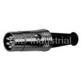
DIN Connectors 3 PIN MALE PLUG 05BL3M
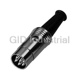
Conn DIN Connector PL 5 POS Solder ST Cable Mount 5 Terminal 1 Port 05BL5M
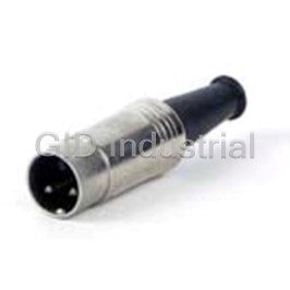
Conn DIN Connector M 5 POS Crimp ST Cable Mount 5 Terminal 1 Port 05BL5MX
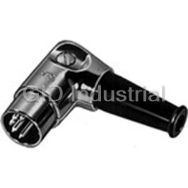
Conn DIN Connector M 3 POS RA Cable Mount 3 Terminal 1 Port 05DL3M
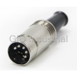
Conn DIN Connector M 5 POS RA Cable Mount 5 Terminal 1 Port 05DL5M
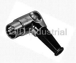
Conn DIN Connector M 5 POS RA Cable Mount 5 Terminal 1 Port 05DL5MX
Request a Quote

The quote request has been received
Close

Facing challenges or have inquiries? Feel free to contact us!
Call Us +1-469-283-2440
What they say about us
FANTASTIC RESOURCE
One of our top priorities is maintaining our business with precision, and we are constantly looking for affiliates that can help us achieve our goal. With the aid of GID Industrial, our obsolete product management has never been more efficient. They have been a great resource to our company, and have quickly become a go-to supplier on our list!
Bucher Emhart Glass
EXCELLENT SERVICE
With our strict fundamentals and high expectations, we were surprised when we came across GID Industrial and their competitive pricing. When we approached them with our issue, they were incredibly confident in being able to provide us with a seamless solution at the best price for us. GID Industrial quickly understood our needs and provided us with excellent service, as well as fully tested product to ensure what we received would be the right fit for our company.
Fuji
HARD TO FIND A BETTER PROVIDER
Our company provides services to aid in the manufacture of technological products, such as semiconductors and flat panel displays, and often searching for distributors of obsolete product we require can waste time and money. Finding GID Industrial proved to be a great asset to our company, with cost effective solutions and superior knowledge on all of their materials, it’d be hard to find a better provider of obsolete or hard to find products.
Applied Materials
CONSISTENTLY DELIVERS QUALITY SOLUTIONS
Over the years, the equipment used in our company becomes discontinued, but they’re still of great use to us and our customers. Once these products are no longer available through the manufacturer, finding a reliable, quick supplier is a necessity, and luckily for us, GID Industrial has provided the most trustworthy, quality solutions to our obsolete component needs.
Nidec Vamco
TERRIFIC RESOURCE
This company has been a terrific help to us (I work for Trican Well Service) in sourcing the Micron Ram Memory we needed for our Siemens computers. Great service! And great pricing! I know when the product is shipping and when it will arrive, all the way through the ordering process.
Trican Well Service
GO TO SOURCE
When I can't find an obsolete part, I first call GID and they'll come up with my parts every time. Great customer service and follow up as well. Scott emails me from time to time to touch base and see if we're having trouble finding something.....which is often with our 25 yr old equipment.
ConAgra Foods