

 Manufacturers
TE CONNECTIVITY 1-1393254-5
Description
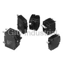
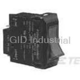
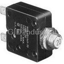
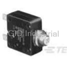
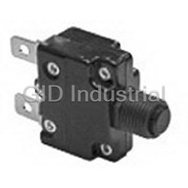
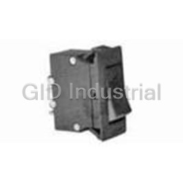
Circuit Breaker Hydraulic Magnetic
1-1393254-5
Part Number
1-1393254-5
Price
Request Quote
Manufacturer
TE CONNECTIVITY
Lead Time
Request Quote
Category
Circuit Protection » Circuit Breaker
Specifications
Manufacturer
TE Connectivity
Manufacturers Part #
1-1393254-5
Industry Aliases
W91-X1040-50
Sub-Category
Circuit Breakers
Brand
AMP
Factory Pack Quantity
24
Datasheet
DDEController?Action=srchrtrv&DocNm=1308242_w6w9&DocType=Data+Sheet&DocLang=English&PartCntxt=5-1393252-6.pdf
499 KiB

Extracted Text
General Purpose Relays Industrial Relays Potter & Brumfield W6/W9 Series Magnetic Hydraulic P&B Circuit Breakers n Designed for the international market. UL Recognzied (UL1077 and UL1500), CSA Accepted and VDE approved. n Ratings to 50 amps. n Heavy duty #10-32 stud connections. (W9) n Quick-connect or screw terminals. (W6) n Several delay curve options. n Trip-free operation. Agency Approvals UL: Recognized as Supplementary Protector under UL 1077. Available Mechanical/Environmental Data (continued) models meet Ignition Protection requirements in accordance with Fungus and Moisture Resistance: UL1500. File E69543 Special moisture resistant finish applied to all ferrous parts. CSA: Accepted as a Supplementary Protector. File LR15734. Plastic parts are made of inherently fungus resistant material. VDE: Approved to VDE 0642/EN 60 934 (Circuit Breakers for Equipment) Marking: License No. 73782 International “1” and “0” symbols are marked on the toggle for both W6 and Users should thoroughly review the technical data before selecting a product part number. W9. W9 units have “ON” and “OFF” molded into the area at the base of the It is recommended that users also seek out the pertinent approvals files of the agencies/ toggle. laboratories and review them to confirm the product meets the requirements for a given Mounting: application. Units are mounted with two #6-32 screws from the front of the panel. Metric models for use with M3 x 0.5 screws are available. To maintain Electrical Data published performance specifications, units should not be mounted more Calibration: than 90° from their normal upright position. Breakers will hold 100% of rated current. Weight: Approximately 2.5 ounces per pole. Breakers may trip between 101% and 124% of rated load (134% for AC/ DC units). Breakers must trip at 125% of rated load and above (135% for AC/DC Approvals and Ratings Table 1 units). Dielectric Strength: 50/60 Hz., 1500V: DC, 1100V Insulation Resistance: 100 Megaohms at 500VDC W6 Series UL1077/CSA (All Circuit Functions) Endurance: Current Interrupting 10,000 on/off cycles - 6000 at rated load, 4000 at no load. Maximum Frequency Phase Rating Capacity Units tested at six cycles per minute, 1 second on and 9 seconds off at Voltage (Hz) (Amps) (Amps) 25°C ambient. 65 DC - 0.2 - 50 2,000 277 50/60 1 0.2 - 20 5,000 Typical Resistance and Impedance 277 50/60 1 21 - 50 2,500 Current DC 50/60 277/480 50/60 3Ø-Wye 0.2 - 20 5,000 (Amps.) Resistance Impedance (Ohms) (Ohms) W9 Series UL1077/CSA (All Circuit Functions) 0.2 90 90 1.0 1.2 1.2 Current Interrupting Maximum Frequency 2.0 0.28 0.28 Phase Rating Capacity Voltage (Hz) 5.0 0.04 0.04 (Amps) (Amps) 10.0 0.013 0.013 65 DC - 0.2 - 50 2,000 20.0 0.004 0.005 277 50/60 1 0.2 - 50 5,000 30.0 0.0027 0.004 277/480 50/60 3Ø-Wye 0.2 - 20 5,000 40.0 0.002 0.002 50.0 0.0015 0.0015 W6 or W9 Series VDE (Circuit Function X) Tolerance: 0.1 - 4.99 ± 15%; 5 - 9.99 ± 20%; 10 - 15 ± 25%; 16 - 30 ± 50%. Current Interrupting Maximum Frequency Phase Rating Capacity Voltage (Hz) (Amps) (Amps) Mechanical/Environmental Data Operating Temperature: -40°C to +85°C. 65 DC - 0.2 - 50 2,000 Humidity: Meets requirements of Mil-STD-202 method 103. 250 50/60 1 0.2 - 30 5,000 Shock: Tested per Mil-STD-202, method 213, test condition C 250 50/60 1 31 - 50 2,000 (100g @ 6 ms) 415/240 50/60 3Ø 0.2 - 30 5,000 Vibration: Tested per Mil-STD-202, method 201, 10-55 Hz., 0.06” (1.52mm) total excursion in 2 planes. W6 or W9 Series UL1500 (Circuit Function X) Current Interrupting Maximum Frequency Phase Rating Capacity Voltage (Hz) (Amps) (Amps) 48 DC - 0.2 - 50 3,000 125/250 50/60 1 0.2 - 50 1,000 250 50/60 3Ø-Wye 0.2 - 50 1,000 1 11-2015, Rev. 1115 Datasheets and product specification Datasheets and product data is subject to the Datasheets, product data, ‘Definitions’ sec- www.te.com according to IEC 61810-1 and to be used terms of the disclaimer and all chapters of tion, application notes and all specifications © 2014 Tyco Electronics Corporation, only together with the ‘Definitions’ section. the ‘Definitions’ section, available at are subject to change. a TE Connectivity Ltd. company http://relays.te.com/definitions General Purpose Relays Industrial Relays Potter & Brumfield W6/W9 Series Magnetic Hydraulic P&B Circuit Breakers (Continued) Time vs Current Trip Curves For W6 Series and W9 Series AC 50/60 Hz. DC & 50/60 Hz. 400 Hz. CURVE 3 SHORT DELAY 50/60 Hz. CURVE 0 INSTANTANEOUS CURVE 2 STANDARD DELAY 50/60 Hz. 10,000 10,000 TRIP TIMES 10,000 OVERLOAD TRIP TIMES OVERLOAD TRIP TIMES (SEC.) OVERLOAD @ 50/60 Hz . & DC @ 400 Hz. 1000 (SEC.) 1000 1000 125% 1 - 15 125% 100 ms max. May Trip 125% 10 - 150 200% .15 - 1.5 150% 55 ms max. 100 ms max. 100 200% 2.2 - 20 100 100 400% .03 - .25 200% 30 ms max. 30 ms max. 400% .2 - 2 600% .007 - .15 400% 15 ms max. 15 ms max. 10 600% .03 - .75 10 800% .003 - .08 600% 12 ms max. 12 ms max. 10 800% .007 - .15 1000% .003 - .04 800% 12 ms max. 12 ms max. 1000% .005 - .04 1 1 1 .1 .1 .1 .01 .01 .01 .001 .001 .001 100 200 300 400 500 600 700 800 900 1000 1100 1200 100 200 300 400 500 600 700 800 900 1000 1100 1200 0 100 200 300 400 500 600 700 800 900 1000 1100 1200 0 125 150 LOAD CURRENT AS A PERCENT 125 150 0 LOAD CURRENT AS A PERCENT 125 150 LOAD CURRENT AS A PERCENT OF BREAKER RATING OF BREAKER RATING OF BREAKER RATING MOTOR START / LONG DELAY CURVE 12 HIGH INRUSH 50/60 Hz. CURVE 13 HIGH INRUSH 50/60 Hz. 10,000 CURVE 10 HIGH INRUSH 50/60 Hz. AC 10,000 10,000 OVERLOAD TRIP TIMES OVERLOAD TRIP TIMES OVERLOAD TRIP TIMES (SEC.) (SEC.) (SEC.) 1000 1000 125% 10 - 150 1000 125% 40 - 500 125% .8 - 30 200% 9 - 100 200% 3 - 25 100 200% .15 - 2.5 400% 2 - 20 100 400% .5 - 2.5 100 400% .03 - .3 600% .8 - 10 600% .15 - 1 800% .1 - 4.5 600% .02 - .15 10 1000% .009 - 2 800% .015 - .7 10 800% .009 - .12 10 1000% .009 - .35 1000% .009 - .09 1 1 1 .1 .1 .1 .01 .01 .01 .001 100 200 300 400 500 600 700 800 900 1000 1100 .0 011200 .001 0 100 200 300 400 500 600 700 800 900 1000 1100 1200 100 200 300 400 500 600 700 800 900 1000 1100 1200 125 150 0 LOAD CURRENT AS A PERCENT 125 150 0 LOAD CURRENT AS A PERCENT 125 150 OF BREAKER RATING LOAD CURRENT AS A PERCENT OF BREAKER RATING OF BREAKER RATING DC CURVE 3 SHORT DELAY DC CURVE 2 STANDARD DELAY DC CURVE 53 DC HIGH INRUSH 10,000 10,000 10,000 OVERLOAD TRIP TIMES OVERLOAD TRIP TIMES OVERLOAD TRIP TIMES (SEC.) (SEC.) (SEC.) 1000 1000 1000 125% .6 - 7 125% 80 - 700 125% 2 - 55 200% 15 - 150 200% .16 - 1.5 200% .60 - 8 100 100 400% 2 - 20 400% .03 - .25 100 400% .1 - 1.5 600% .70 - 10 600% .01 - .13 600% .02 - .5 800% .10 - 3 10 10 800% .004 - .05 1000% .01 - .1 800% .004 - .05 10 1000% .003 - .015 1000% .004 - .025 1 1 1 .1 .1 .1 .01 .01 .01 .001 .001 100 200 300 400 500 600 700 800 900 1000 1100 1200 100 200 300 400 500 600 700 800 900 1000 1100 1200 .001 0 0 125 150 125 150 LOAD CURRENT AS A PERCENT 100 200 300 400 500 600 700 800 900 1000 1100 1200 LOAD CURRENT AS A PERCENT 0 OF BREAKER RATING 125 150 OF BREAKER RATING LOAD CURRENT AS A PERCENT OF BREAKER RATING AC/DC CURVE 34 DC, 50/60 Hz. STANDARD DELAY 10,000 OVERLOAD TRIP TIMES (SEC.) 1000 135% 1 - 90 200% .60 - 20 100 400% .095 - 2 600% .02 - .95 10 800% .002 - .45 1000% .002 - .09 1 .1 .01 .001 100 200 300 400 500 600 700 800 900 1000 1100 1200 0 125 150 LOAD CURRENT AS A PERCENT 135 OF BREAKER RATING Note: For instantaneous curves for all voltages refer to Curve 0 instananeous under the AC 50/60 Hz. heading 2 11-2015, Rev. 1115 Datasheets and product specification Datasheets and product data is subject to the Datasheets, product data, ‘Definitions’ sec- www.te.com according to IEC 61810-1 and to be used terms of the disclaimer and all chapters of tion, application notes and all specifications © 2014 Tyco Electronics Corporation, only together with the ‘Definitions’ section. the ‘Definitions’ section, available at are subject to change. a TE Connectivity Ltd. company http://relays.te.com/definitions TIME IN SECONDS TIME IN SECONDS TIME IN SECONDS TIME IN SECONDS TIME IN SECONDS TIME IN SECONDS TIME IN SECONDS TIME IN SECONDS TIME IN SECONDS TIME IN SECONDS General Purpose Relays Industrial Relays P Pott otter & Brumfield er & Brumfield W6/W9 Series Magnetic Hydraulic P&B Circuit Breakers (Continued) Product code structure Typical product code W 67- X 2 Q 1 2- 20 W6 Series Circuit Breaker Mounting W #6-32 mounting threads M M3.0 x 0.5 mounting threads Number of Poles 67 Single Pole 68 Two Pole 69 Three Pole 70 Four Pole Circuit Function (Only X is VDE approved) X Series trip Actuator One actuator per pole 1 Black toggle 9 Red toggle 2 White toggle One actuator per unit 7 Black toggle 8 White toggle Termination Q .250“ QC (DIN 46 244) [30A Max. UL/CSA; 25A Max. VDE] S #8-32 screw [30A Max.] T #10-32 screw [50A Max.] U #8-32 screw, nickel plated, bent inward 30° [30A Max.] V #10-32 screw, nickel plated, bent inward 30° [30A Max.] Notes: #10-32 termination must be used for all ratings of greater than 30 amps. #10-32 termination must be specified for circuit function D, but relay trip pole will be equipped with .250“ QC. Maximum Line Voltage (see Table 1 for current ranges) UL/CSA 1 277VAC, 50/60 Hz. Types 2 277/480VAC, 50/60 Hz. [20A Max.] (Requires insulating barriers, see outline dimension drawing) 5 65VDC 7 AC/DC 277VAC, 50/60 Hz. or 65VDC (Time delay curve 34 must be specified) 8 AC/DC 120VAC, 120/240VAC, 48VDC (Agency Approval M [UL1500] and time delay curve 34 must be specified) VDE 1 250VAC, 415/240VAC Types 5 65VDC 7 AC/DC 250VAC, 415/240VAC, 65VDC (Time delay curve 34 must be specified) Time Delay Curve 0 Instantaneous 10 AC high inrush motor start / long delay 2 Standard delay 12 AC high inrush version of #2 3 Short delay 13 AC high inrush version of #3 53 DC high inrush 34 Combination AC/DC standard delay Amp Rating 0.2 0.50 1.0 2.0 3.0 4.0 6.0 7.5 9.0 11.0 15.0 25.0 35.0 45.0 Consult factory for 0.25 0.75 1.5 2.5 3.5 5.0 7.0 8.0 10.0 12.0 20.0 30.0 40.0 50.0 other values Agency Approval Blank UL1077/CSA breaker V VDE approved breaker M UL1077/UL1500 ignition protected breaker Authorized distributors are more likely to stock the following items. W67-X2Q10-3 W67-X2Q12-10 W67-X2Q13-3 W67-X2Q50-5 W67-X2Q52-30 W68-X2Q12-10 W68-X2Q110-10 W69-X2Q12-25 W67-X2Q10-5 W67-X2Q12-15 W67-X2Q13-10 W67-X2Q50-10 W67-X2Q110-15 W68-X2Q12-15 W68-X2Q110-20 W69-X2Q12-30 W67-X2Q12-2 W67-X2Q12-20 W67-X2Q13-15 W67-X2Q52-5 W67-X2Q110-20 W68-X2Q12-20 W69-X2Q12-5 W69-X2Q110-20 W67-X2Q12-3 W67-X2Q12-30 W67-X2Q13-20 W67-X2Q52-10 W68-X2Q12-3 W68-X2Q12-25 W69-X2Q12-10 W69-X2Q110-30 W67-X2Q12-5 W67-X2Q13-1 W67-X2Q13-25 W67-X2Q52-15 W68-X2Q12-5 W68-X2Q12-30 W69-X2Q12-15 W67-X2Q12-7 W67-X2Q13-2 W67-X2Q13-30 W67-X2Q52-20 W68-X2Q12-7 W68-X2Q13-15 W69-X2Q12-20 3 11-2015, Rev. 1115 Datasheets and product specification Datasheets and product data is subject to the Datasheets, product data, ‘Definitions’ sec- www.te.com according to IEC 61810-1 and to be used terms of the disclaimer and all chapters of tion, application notes and all specifications © 2014 Tyco Electronics Corporation, only together with the ‘Definitions’ section. the ‘Definitions’ section, available at are subject to change. a TE Connectivity Ltd. company http://relays.te.com/definitions General Purpose Relays Industrial Relays P Pott otter & Brumfield er & Brumfield W6/W9 Series Magnetic Hydraulic P&B Circuit Breakers (Continued) Product code structure Typical product code W 91- X 1 1 2- 20 W9 Series Circuit Breaker Mounting W #6-32 mounting threads M M3.0 x 0.5 mounting threads Number of Poles 91 Single Pole 92 Two Pole 93 Three Pole 94 Four Pole Circuit Function (Only X is VDE approved) X Series trip Actuator One actuator per pole 1 Black toggle 2 White toggle Maximum Line Voltage (see Table 1 for current ranges) UL/CSA 1 277VAC, 50/60 Hz. Types 2 277/480VAC, 50/60 Hz. [20A Max.] 5 65VDC 7 AC/DC 277VAC, 50/60 Hz. or 65VDC (Time delay curve 34 must be specified) 8 AC/DC 120VAC, 120/240VAC, 48VDC (Agency Approval M [UL1500] and time delay curve 34 must be specified) VDE 1 250VAC, 415/240VAC Types 5 65VDC 7 AC/DC 250VAC, 415/240VAC, 65VDC (Time delay curve 34 must be specified) Time Delay Curve 0 Instantaneous 10 AC high inrush motor start / long delay 2 Standard delay 12 AC high inrush version of #2 3 Short delay 13 AC high inrush version of #3 53 DC high inrush 34 Combination AC/DC standard delay Amp Rating 0.20 0.75 2.0 3.5 6.0 8.0 11.0 20.0 35.0 50.0 0.25 1.00 2.5 4.0 7.0 9.0 12.0 25.0 40.0 Consult factory for other values 0.50 1.50 3.0 5.0 7.5 10.0 15.0 30.0 45.0 Agency Approval Blank UL1077/CSA approved breaker V VDE approved breaker M UL1077/UL1500 ignition protected breaker Authorized distributors are more likely to stock the following items. W91-X112-1 W91-X112-15 W91-X113-15 W91-X152-40 W92-X112-5 W92-X112-30 W92-X1110-30 W93-X112-30 W91-X112-2 W91-X112-20 W91-X150-5 W91-X152-50 W92-X112-7 W92-X112-40 W93-X112-5 W93-X112-40 W91-X112-3 W91-X112-40 W91-X152-10 W91-X1110-20 W92-X112-10 W92-X112-50 W93-X112-10 W93-X112-50 W91-X112-5 W91-X112-50 W91-X152-15 W92-X112-1 W92-X112-15 W92-X113-15 W93-X112-15 W93-X1110-20 W91-X112-7 W91-X113-5 W91-X152-20 W92-X112-2 W92-X112-20 W92-X113-20 W93-X112-20 W93-X1110-30 W91-X112-10 W91-X113-10 W91-X152-30 W92-X112-3 W92-X112-25 W92-X1110-20 W93-X112-25 4 11-2015, Rev. 1115 Datasheets and product specification Datasheets and product data is subject to the Datasheets, product data, ‘Definitions’ sec- www.te.com according to IEC 61810-1 and to be used terms of the disclaimer and all chapters of tion, application notes and all specifications © 2014 Tyco Electronics Corporation, only together with the ‘Definitions’ section. the ‘Definitions’ section, available at are subject to change. a TE Connectivity Ltd. company http://relays.te.com/definitions General Purpose Relays Industrial Relays Potter & Brumfield W6/W9 Series Magnetic Hydraulic P&B Circuit Breakers (Continued) Outline Dimensions - Toggle Actuator Models W6 Series Panel Mounting Cutout 2.043 .750 .66 Ø .625 +.010 (51.89) (19.05) .235 1.640 (16.8) -.000 (5.97) (41.66) .245 15.88 +0.25 (6.22) ( ) -0.00 ON 1 PER POLE A LINE 29° 1.660 (42.16) 1.048 1.520 (26.62) 30° (38.61) OFF B Ø .156 LOAD [2 PLACES PER POLE] (3.96) W6 Series - One Actuator Per Pole 1 Pole 2 Pole 3 Pole 4 Pole Ø .590 (15.00) .750 2.250 3.000 1.500 (19.05) (57.15) (76.20) (38.10) 1.660 2.000 (42.16) (50.80) 1.05 1.22 (26.67) (31.00) 6.32 TH'D. .14 (3.56) DP. TYP. M3 X 0.5 OPTIONAL Note: Multi-pole models furnished with seperate handle tie hardware W6 Series - One Actuator Per Unit 1 Pole 2 Pole 3 Pole 4 Pole Ø .590 (15.00) .750 2.250 3.000 1.500 (19.05) (57.15) (76.20) (38.10) 1 .660 2.000 (42.16) (50.80) 1.05 1.22 (26.67) (31.00) 6.32 TH'D. .14 (3.56) DP. TYP. M3 X 0.5 OPTIONAL Note: 4-pole models furnished with sperate handle tie hardware 480V Model with Barriers 2.250 2.778 (57.15) .269 (70.56) (6.83) 2.530 (64.26) .235 2.032 Termination Options 2.380 (5.97) (51.61) (60.45) LINE LINE LINE LINE .266 .416 (6.76) A A A 1.058 (10.56) Note: 3-pole model shown C (26.97) .827 (21.00) NO 1.520 (38.61) Notes: 1. Terminal protrusion dimensions are referenced from back of mounting panel NC 2. Main terminals are male quick connect type .250 (6.35) wide x .031 (.79) thick x B B B LOAD .377 (9.58) long. Optional 8-32 x .250 (6.35) or 10-32 x .250 (6.35) screw type LOAD LOAD LOAD 3. Panel mounting cutout detail mtg. detail tol.: ± .005 (.13) unless noted. Add additional cutouts to correspond to number of poles. Outline drawing tolerance ± .015 (.35) unless noted 5 11-2015, Rev. 1115 Datasheets and product specification Datasheets and product data is subject to the Datasheets, product data, ‘Definitions’ sec- www.te.com according to IEC 61810-1 and to be used terms of the disclaimer and all chapters of tion, application notes and all specifications © 2014 Tyco Electronics Corporation, only together with the ‘Definitions’ section. the ‘Definitions’ section, available at are subject to change. a TE Connectivity Ltd. company http://relays.te.com/definitions General Purpose Relays Industrial Relays Potter & Brumfield W6/W9 Series Magnetic Hydraulic P&B Circuit Breakers (Continued) Outline Dimensions - Optional Toggle Guards W6 Series .625 INSIDE 1.375 INSIDE 2.185 INSIDE (15.88) (34.92) (55.50) 1.093 .03 .313 (27.76) (.76) (7.95) .313 .75 .75 .75 (7.95) (19.05) (19.05) (19.05) .2 x .47 R1.0 (11.94) .78 .95 (25.4) .17 (19.8) (24.1) (4.32) .17 REF. .08 .625 (4.32) (2.03) (15.88) 2.00 (50.8) 1.66 (42.16) 2 x .27 DIA. .44 (6.86) (11.18) .53 84-004 toggle guard shown with 2 x .16 DIA. 4 x .16 DIA. 6 x .16 DIA. .20 (13.46) (4.06) (4.06) (4.06) (5.08) W67 series circuit breaker mounted in a panel. 84-004 84-005 84-006 (for 1 Pole (for 2 Pole (for 3 Pole Breaker) Breaker) Breaker) Optional toggle guards may be ordered seperately for use on W6 toggle actuator models. These guards help to prevent accidental operation and allow the breaker to be locked in the “off” position. 6 11-2015, Rev. 1115 Datasheets and product specification Datasheets and product data is subject to the Datasheets, product data, ‘Definitions’ sec- www.te.com according to IEC 61810-1 and to be used terms of the disclaimer and all chapters of tion, application notes and all specifications © 2014 Tyco Electronics Corporation, only together with the ‘Definitions’ section. the ‘Definitions’ section, available at are subject to change. a TE Connectivity Ltd. company http://relays.te.com/definitions General Purpose Relays Industrial Relays Potter & Brumfield W6/W9 Series Magnetic Hydraulic P&B Circuit Breakers (Continued) Outline Dimensions W9 Series Series Trip Model Series Trip Model .060 .750 .375 .750 .750 1.845 (1.52) (19.05) (9.53) (19.05) (19.05) .398 (46.86) .375 .375 .313 .750 .281 (10.11) 1.15 (9.53) (9.52) (7.95) (19.05) (7.14) (29.21) LINE .060 ON ON ON ON ON ON ON ON ON ON ON (1.52) .218 29° 1.438 (5.54) (36.53) 1.940 2.065 (49.28) 2.50 30° (52.45) OFF OFF OFF OFF OFF OFF OFF OFF OFF OFF (63.5) OFF LOAD #10-32 .14 2 POLE STUD 1 POLE (3.56) 1.500 TERMINATION 2.10 (38.10) (53.34) 2.250 3 POLE TAPPED #6-32 X .16 (4.06) 2.50 .74 (57.15) DEEP 3.000 (64.00) (18.8) 4 POLE M3 X 0.5 OPTIONAL (76.20) Note: 1. Top mounted plate (shown with broken line) is present only on UL1500 models Panel Mounting Cutout Detail .750 .750 (19.05) (19.05) .732 .750 .385 (18.59) (19.05) (9.78) .907 (23.04) 1.450 (36.83) 2.065 (52.45) .76 2X Ø .156 1 POLE (19.3) (3.96) 1.52 2 POLE PER POLE (38.6) 2.28 3 POLE (57.9) 3.04 4 POLE (77.2) Notes: 1. Terminal protrusion dimensions are referenced from the back of the mounting panel 2. Mounting detail tolerance ± .005 (13) unless noted 3. Outline drawing tolerance ± .015 (.38) unless noted Dimensions in brackets ( ) are in milimeters. Disclaimer: While TE and its affiliates referenced herein have made every reasonable effort to ensure the accuracy of the information contained in this document, TE cannot assure that this information is error free. For this reason, TE does not make any representation or offer any guarantee that such information is accurate, correct, reliable or current. TE reserves the right to make any adjustments to the information at any time. TE expressly disclaims any implied warranty regarding the information contained herein, including, but not limited to, the implied warranties of merchantability or fitness for a particular purpose. TE‘s only obligations are those stated in TE’s Standard Terms and Conditions of Sale. TE will in no case be liable for any incidental, indirect or consequential damages arising from or in connection with, including, but not limited to, the sale, resale, use or misuse of its products. Users should rely on their own judgment to evaluate the suitability of a product for a certain purpose and test each product for its intended application. In case of any potential ambiguities or questions, please don’t hesitate to contact us for clarification. 7 11-2015, Rev. 1115 Datasheets and product specification Datasheets and product data is subject to the Datasheets, product data, ‘Definitions’ sec- www.te.com according to IEC 61810-1 and to be used terms of the disclaimer and all chapters of tion, application notes and all specifications © 2014 Tyco Electronics Corporation, only together with the ‘Definitions’ section. the ‘Definitions’ section, available at are subject to change. a TE Connectivity Ltd. company http://relays.te.com/definitions
Frequently asked questions
How does Electronics Finder differ from its competitors?

Is there a warranty for the 1-1393254-5?
Which carrier will Electronics Finder use to ship my parts?
Can I buy parts from Electronics Finder if I am outside the USA?
Which payment methods does Electronics Finder accept?
Why buy from GID?

Quality
We are industry veterans who take pride in our work

Protection
Avoid the dangers of risky trading in the gray market

Access
Our network of suppliers is ready and at your disposal

Savings
Maintain legacy systems to prevent costly downtime

Speed
Time is of the essence, and we are respectful of yours
Related Products
Circuit Breaker Thermal 2Pole 20A 250VAC/50VDC 1-1393248-0
Circuit Breaker Thermal 1Pole 18A 250VAC/50VDC 1-1393249-0
Circuit Breaker Thermal 1Pole 25A 250VAC/50VDC 1-1393249-3
Circuit Breaker Thermal 1Pole 5A 250VAC 1-1423364-2
Circuit Breaker Thermal 1Pole 10A 250VAC 1-1423364-4
Circuit Breaker Thermal 1Pole 7A 250VAC 1-1423673-0
Request a Quote

The quote request has been received
Close

Facing challenges or have inquiries? Feel free to contact us!
Call Us +1-469-283-2440
What they say about us
FANTASTIC RESOURCE
One of our top priorities is maintaining our business with precision, and we are constantly looking for affiliates that can help us achieve our goal. With the aid of GID Industrial, our obsolete product management has never been more efficient. They have been a great resource to our company, and have quickly become a go-to supplier on our list!
Bucher Emhart Glass
EXCELLENT SERVICE
With our strict fundamentals and high expectations, we were surprised when we came across GID Industrial and their competitive pricing. When we approached them with our issue, they were incredibly confident in being able to provide us with a seamless solution at the best price for us. GID Industrial quickly understood our needs and provided us with excellent service, as well as fully tested product to ensure what we received would be the right fit for our company.
Fuji
HARD TO FIND A BETTER PROVIDER
Our company provides services to aid in the manufacture of technological products, such as semiconductors and flat panel displays, and often searching for distributors of obsolete product we require can waste time and money. Finding GID Industrial proved to be a great asset to our company, with cost effective solutions and superior knowledge on all of their materials, it’d be hard to find a better provider of obsolete or hard to find products.
Applied Materials
CONSISTENTLY DELIVERS QUALITY SOLUTIONS
Over the years, the equipment used in our company becomes discontinued, but they’re still of great use to us and our customers. Once these products are no longer available through the manufacturer, finding a reliable, quick supplier is a necessity, and luckily for us, GID Industrial has provided the most trustworthy, quality solutions to our obsolete component needs.
Nidec Vamco
TERRIFIC RESOURCE
This company has been a terrific help to us (I work for Trican Well Service) in sourcing the Micron Ram Memory we needed for our Siemens computers. Great service! And great pricing! I know when the product is shipping and when it will arrive, all the way through the ordering process.
Trican Well Service
GO TO SOURCE
When I can't find an obsolete part, I first call GID and they'll come up with my parts every time. Great customer service and follow up as well. Scott emails me from time to time to touch base and see if we're having trouble finding something.....which is often with our 25 yr old equipment.
ConAgra Foods