

 Manufacturers
TE CONNECTIVITY 1-1393774-7
Description
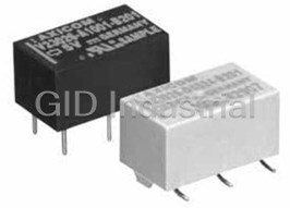
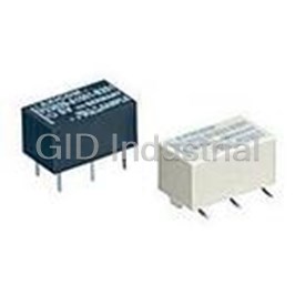
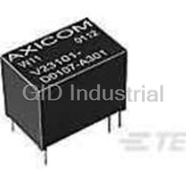
Signal Relay 3VDC 1A SPDT(13x7.6x6.9)mm THT
1-1393774-7
Part Number
1-1393774-7
Price
Request Quote
Manufacturer
TE CONNECTIVITY
Lead Time
Request Quote
Category
Relays and I/O Modules » Signal Relay
Specifications
Manufacturer
TE Connectivity
Manufacturers Part #
1-1393774-7
Industry Aliases
V23026A1006B201
Sub-Category
Signal Relays
Brand
AMP
Factory Pack Quantity
40
Datasheet
DDEController?Action=showdoc&DocId=Specification+Or+Standard%7F108-98009%7FN%7Fpdf%7FEnglish%7FENG_SS_108-98009_N.pdf
2095 KiB

Extracted Text
Signal Relays AXICOM P1 Relay V23026 n Directly triggerable with TTL standard modules as ALS, HCT & ACT n Slim line 13.5x7.85mm (0.531x0.309”) n Switching current 1 A n Bifurcated 1 form C (CO) contact n Immersion cleanable AXICOM n High sensitivity results in low nominal power consumption, Telecom-, Signal and RF Relays 65 to 108-98009 Rev. E 130mW for monostable and 30 to 150mW for bistable (latching) P1 V23026 Relay n Initial surge withstand voltage 2.5kV (2/10μs) meets the Bellcore Requirement GR-1089 P1_THTSMD 1.5kV (10/160μs) meets FCC Part 68 Contact Data Typical applications Automotive equipment, CAN bus, imobilizer, office equipment, measurement Number of contacts and type 1 changeover contact Z and control equipment, medical equipment, safety equipment Contact assembly Bifurcated contact Contact material Palladium nickel, gold-rhodium covered Approvals Coil Data Limiting continuous current at max. ambient temperature 1 A UL 508 File No. E 111441 Magnetic system polarized Coil voltage range 3 to 24VDC Technical data of approved types on request Maximum switching current 1 A other coil voltages on request Maximum swichting voltage 125 Vdc Operative range, IEC 61810 see coil operative range 150 Vac Contact Data Max. coil temperature 85°C Contact arrangement 1 form C (CO) Thermal resistance <130K/W Maximum switching capacity 30 W, 60 VA Max. switching voltage 125VDC, 150VAC Rated current 1A Coil versions, THT, monostable Thermoelectric potential < 100 µV Limiting continuous current, 85°C 1A Coil Rated Operate Release Coil Rated coil Initial contact resistance / measuring condition: 10 mA / 20 mV < 50 m Breaking capacity max. see max. DC load breaking capacity code voltage voltage voltage resistance power Contact material Palladium nickel, VDC VDC 7 VDC Ω ±10% mW min. min. Electrical endurance at 12 V / 10 mA typ. 5 x 10 operations gold-rhodium covered 006 3 2.25 0.3 137 66 7 at 6 V / 100 mA typ. 1 x 10 operations Contact style bifurcated contact 001 5 3.75 0.5 370 68 4 at 30 V / 1000 mA typ. 1 x 10 operations Min. recommended contact load 10mA at 20mV 005 9 6.75 0.9 1165 70 Initial contact resistance ≤50mΩ at 10mA/20mV 002 12 9.00 1.2 2250 34 9 Fr Mechanical endurance equency of operation without load 200 ops./s 004 24 typ. 10 operations 18.00 2.4 4500 128 Operate/release time max. 2ms All figures are given for coil without pre-energization, at ambient temperature +23°C. UL contact ratings 30 Vdc / 1 A Set/reset time max. 2ms 65 Vdc / 0.46 A Bounce time max. 3ms Coil versions, SMT, monostable 150 Vac / 0.46 A Electrical endurance Coil Rated Operate Release Coil Rated coil 6 at 12V/10mA typ. 50x10 operations code voltage voltage voltage resistance power AXICOM 6 at 6V/100mA typ. 10x10 operations VDC VDC VDC Ω ±10% mW min. min. Telecom-, Signal and RF Relays 108-98009 Rev. E 3 at 30V/1000mA typ. 10x10 operations 026 3 2.25 0.3 113 80 Contact ratings 021 5 3.75 0.5 313 80 P1 V23026 Relay UL contact ratings, resistive load 30VDC/1A 025 9 6.75 0.9 1015 80 65VDC/0.46A 022 12 9.00 1.2 1800 80 150VAC/0.46A 024 24 18.00 2.4 4500 128 Max. DC Load Breaking Capacity 9 All figures are given for coil without pre-energization, at ambient temperature +23°C. Mechanical endurance typ. 10 operations Coil Operating Range Max. DC load breaking capacity Coil operative range, monostable DC coil U = Nominal coil voltage nom 65 mW U = Upper limit of the operative range of max. 130 mW the coil voltage (limiting voltage) when coils are continously energized Umax. at 0 A U = Lower limit of the operative range of Umax. at 0 A Umax. at - 1 A op. min. the coil voltage (reliable operate voltage) U = Lower limit of the operative range of rel. min. the coil voltage (reliable release voltage) Unom. nominal coil voltage Uop. min. Urel. min. Ambient Temperature [°C] 1 65 mW Latching Umax. - 5 % coil duty at 1 A 03-2017, Rev. 0317 Datasheets and product specification Datasheets and product data is subject to the Datasheets, product data, ‘Definitions’ sec- 32 mW Latching www.te.com according to IEC 61810-1 and to be used terms of the disclaimer and all chapters of tion, application notes and all specifications © 2011 Tyco Electronics Corporation, only together with the ‘Definitions’ section. the ‘Definitions’ section, available at are subject to change. a TE Connectivity Ltd. company http://relays.te.com/definitions Umax. - 100 % coil duty at 0 A Umax. - 5 % coil duty at 0 A Unom. nominal coil voltage All specifications subject to change. Consult Tyco Electronics for latest specifications. 7 of 12 Uset min. Ambient Temperature [°C] All specifications subject to change. Consult Tyco Electronics for latest specifications. 5 of 12 Coil Voltage [U/Unom] Coil Voltage [U/Unom] Signal Relays AXICOM P1 Relay V23026 (Continued) Coil data (continued) Insulation Data Initial dielectric strength Coil versions, THT and SMT, bistable 2 coils between open contacts 500V rms Coil Rated Set Reset Coil Rated coil between contact and coil 1500V rms code voltage voltage voltage resistance power Initial surge withstand voltage VDC VDC VDC Ω ±10% mW between contact and coil 2500V 106 3 2.25 2.25 130 69 Capacitance 101 5 3.75 3.75 390 64 between open contacts max. 5pF 105 9 6.75 6.75 1200 68 between contact and coil max. 6pF 102 12 9.00 9.00 1500 96 Clearance/creepage 1) 24 between contact and coil 0.75mm All figures are given for coil without pre-energization, at ambient temperature +23°C. between adjacent contacts 0.75mm Coils I and II are identical. 1) A nominal voltage of 24VDC is feasible with a 12VDC coil with a series resistor (1500Ω) RF Data Isolation at 100MHz/900MHz -30.0dB/-18.0dB Coil data (continued) Insertion loss at 100MHz/900MHz -0.12dB/-1.9dB Voltage standing wave ratio (VSWR) AXICOM Coil versions, THT, bistable 1 coil at 100MHz/900MHz 1.06/1.75 Telecom-, Signal and RF Relays 108-98009 Rev. E Coil Rated Set Reset Coil Rated coil code voltage voltage voltage resistance power P1 V23026 Relay VDC VDC VDC Ω ±10% mW Other Data 056 3 2.25 -2.25 300 30 Material compliance: EU RoHS/ELV, China RoHS, REACH, Halogen content 051 5 3.75 -3.75 740 34 refer to the Product Compliance Support Center at 057 9 6.75 -6.75 2160 38 www.te.com/customersupport/rohssupportcenter Coil Operating Range 052 12 9.00 -9.00 4500 32 Ambient temperature -40 to +85°C 054 24 18.00 -18.00 4500 128 Category of environmental protection, U = Nominal coil voltage nom IEC 61810 RT III - immersion cleanable 65 mW U V ibration r = esistance (functional) Upper limit of the operative range of 20g, 200 to 2000Hz max. 130 mW the coil voltage (limiting voltage) 40g, 10 to 200Hz Coil data (continued) Shock resistance (functional) when coils are continously energized Umax. at 0 A IEC 60068-2-27 (half sine) 50 g U = Lower limit of the operative range of Coil versions, SMT Umax. at 0 , bistable 1 coil A Umax. at - 1 A op. min. Terminal type PCB terminals and SMT terminals the coil voltage (reliable operate Coil Rated Set Reset Coil Rated coil Weight max. 2g voltage) code voltage voltage voltage resistance power Resistance to soldering heat THT VDC VDC VDC Ω ±10% mW IEC 60068-2-20 265 °C/10s U = Lower limit of the operative range of rel. min. 051 5 3.75 -3.75 740 34 Resistance to soldering heat SMT the coil voltage (reliable release 052 12 9.00 -9.00 4500 32 IEC 60068-2-58 see reflow profile voltage) A nominal voltage of 24V is feasible with a 12V coil with a series resitor (4500Ω) Moisture sensitive level, JEDEC J-Std-020D MSL3 Unom. nominal coil voltage Other coil voltages on request Washing not recommended All figures are given for coil without pre-energization, at ambient temperature +23°C. Ultrasonic cleaning possible Coils I and II are identical. Uop. min. Packaging unit Urel. min. THT 2000 pcs. SMT 2400 pcs. Ambient Temperature [°C] Coil operative range, bistable U upper limit of the operative range of the coil voltage (limiting voltage) when coils are max 65 mW Latching Umax. - 5 % coil duty at 1 A 32 mW Latching Umax. - 100 % coil duty at 0 A Umax. - 5 % coil duty at 0 A Unom. nominal coil voltage Uset min. Ambient Temperature [°C] continuously energized. U lower limit of the operative range of the coil voltage (reliable operate voltage). op min U lower limit of the operative range of the coil voltage (reliable release voltage). rel min 2 03-2017, Rev. 0317 Datasheets and product specification Datasheets and product data is subject to the Datasheets, product data, ‘Definitions’ sec- www.te.com according to IEC 61810-1 and to be used terms of the disclaimer and all chapters of tion, application notes and all specifications © 2011 Tyco Electronics Corporation, only together with the ‘Definitions’ section. the ‘Definitions’ section, available at are subject to change. a TE Connectivity Ltd. company http://relays.te.com/definitions All specifications subject to change. Consult Tyco Electronics for latest specifications. 5 of 12 Coil Voltage [U/Unom] Coil Voltage [U/Unom] AXICOMAXICOMAXICOM Telecom-, Signal and RF Relays Telecom-, Signal and RF Relays Telecom-, Signal and RF Relays 108-98009 Rev. E 108-98009 Rev. E 108-98009 Rev. E P1 V23026 P1 V23 Rela0 y26 P1 V23 Rela 0 y26 Relay AXICOM Telecom-, Signal and RF Relays 108-98009 Rev. E Dimensions Dimensions Dimensions Dimensions in mm Dimensions in mm Dimensions in mm P1 V23026 Relay AXICOM AXICOM Telecom-, Signal and RF Relays 108-98009 Rev. E THT THT THT SMT SMT SMT Telecom-, Signal and RF Relays 108-98009 Rev. E V23026-x1xxx-B201 V23026-x1xxx-B201 V23026-x1xxx-B201 V23026-x1xxx-B201 V23026-x1xxx-B201 V23026-x1xxx-B201 Dimensions Dimensions in mm mm mm inch mm inch inch mm mm mm inch inch inch P1 V23026 Relay P1 V23026 Relay L 13.00 ± L 0.10 13.00 ± L 0.10 0.512 ± 13.00 ± 0.004 0.100.512 ± 0.004 0.512 ± 0.004 13.40 ± 0.10 13.40 ± 0.10 0.528 ± 13.40 ± 0.10 0.004 0.528 ± 0.004 0.528 ± 0.004 W W 7.60 ± 0.10 W 7.60 ± 0.10 0.299 ± 7.60 ± 0.004 0.100.299 ± 0.004 0.299 ± 0.004 7.75 ± 0.10 7.75 ± 0.10 0.305 ± 7.75 ± 0.10 0.004 0.305 ± 0.004 0.305 ± 0.004 THT SMT H 6.90 – H 0.20 H 6.90 – 0.20 0.272 – 6.90 – 0.008 0.200.272 – 0.008 0.272 – 0.008 8.00 – 0.20 8.00 – 0.20 0.315 – 8.00 – 0.20 0.008 0.315 – 0.008 0.315 – 0.008 V23026-x1xxx-B201 V23026-x1xxx-B201 T 3.50 – T 0.20 T 3.50 – 0.20 0.138 – 3.50 – 0.008 0.200.138 – 0.008 0.138 – 0.008 N/A N/A N/A N/A N/A N/A Dimensions Dimensions in mm mm inch mm inch Dimensions Dimensions in mm T1 T1 N/A T1N/A N/A N/A N/A N/A10.90 – 0.50 10.90 – 0.50 0.429 – 10.90 – 0.50 0.020 0.429 – 0.020 0.429 – 0.020 L 13.00 ± 0.10 0.512 ± 0.004 13.40 ± 0.10 0.528 ± 0.004 T2 T2 5.08 ± 0.15 T2 5.08 ± 0.15 0.200 ± 5.08 ± 0.006 0.150.200 ± 0.006 0.200 ± 0.006 5.08 ± 0.15 5.08 ± 0.15 0.200 ± 5.08 ± 0.15 0.006 0.200 ± 0.006 0.200 ± 0.006 W 7.60 ± 0.10 0.299 ± 0.004 7.75 ± 0.10 0.305 ± 0.004 THT SMT S 0.30 ± S 0.10 S 0.30 ± 0.10 0.012 ± 0.30 ± 0.004 0.100.012 ± 0.004 0.012 ± 0.004 N/A N/A N/A N/A N/A N/A H 6.90 – 0.20 0.272 – 0.008 8.00 – 0.20 0.315 – 0.008 THT SMT V23026-x1xxx-B201 V23026-x1xxx-B201 T S1 3.50 – S1 0.20 N/A S1N/A 0.138 – 0.008 N/A N/A N/A N/A N/A0.85 ± 0.10 0.85 ± 0.10 N/A 0.033 ± 0.85 ± 0.10 0.004 0.033 ± 0.004 0.033 ± 0.004 V23026-x1xxx-B201 V23026-x1xxx-B201 mm inch mm inch T1 S2 N/AS2 N/A S2N/A N/A N/A N/A N/A 10.90 – N/A 0.20 – 0.50 0.15 0.20 – 0.15 0.429 – 0.008 – 0.20 – 0.020 0.15 0.006 0.008 – 0.006 0.008 – 0.006 mm inch mm inch L 13.00 ± 0.10 0.512 ± 0.004 13.40 ± 0.10 0.528 ± 0.004 L 13.00 ± 0.10 0.512 ± 0.004 13.40 ± 0.10 0.528 ± 0.004 T2 5.08 ± 0.15 0.200 ± 0.006 5.08 ± 0.15 0.200 ± 0.006 W 7.60 ± 0.10 0.299 ± 0.004 7.75 ± 0.10 0.305 ± 0.004 W 7.60 ± 0.10 0.299 ± 0.004 7.75 ± 0.10 0.305 ± 0.004 S 0.30 ± 0.10 0.012 ± 0.004 N/A N/A H 6.90 – 0.20 0.272 – 0.008 8.00 – 0.20 0.315 – 0.008 H 6.90 – 0.20 0.272 – 0.008 8.00 – 0.20 0.315 – 0.008 S1 N/A N/A 0.85 ± 0.10 0.033 ± 0.004 T 3.50 – 0.20 0.138 – 0.008 N/A N/A THT Version THT Version THT Version SMT Version SMT Version SMT Version T 3.50 – 0.20 0.138 – 0.008 N/A N/A S2 N/A N/A 0.20 – 0.15 0.008 – 0.006 T1 N/A N/A 10.90 – 0.50 0.429 – 0.020 T1 N/A N/A 10.90 – 0.50 0.429 – 0.020 T2 5.08 ± 0.15 0.200 ± 0.006 5.08 ± 0.15 0.200 ± 0.006 T2 5.08 ± 0.15 0.200 ± 0.006 5.08 ± 0.15 0.200 ± 0.006 S 0.30 ± 0.10 0.012 ± 0.004 N/A N/A S 0.30 ± 0.10 0.012 ± 0.004 N/A N/A S1 N/A N/A 0.85 ± 0.10 0.033 ± 0.004 THT Version SMT Version Signal Relays S1 N/A N/A 0.85 ± 0.10 0.033 ± 0.004 AXICOM 13.0±0.1 13.0±0.1 13.0±0.1 7.60±0.1 7.60±0.1 7.60±0.1 S2 N/A N/A 0.20 – 0.15 0.008 – 0.006 13.4±0.1 13.4±0.1 7.75±0.1 13.4±0.1 7.75±0.1 7.75±0.1 S2 N/A N/A 0.20 – 0.15 0.008 – 0.006 P1 Relay V23026 (Continued) THT Version SMT Version 13.0±0.1 7.60±0.1 THT Version SMT Version 13.4±0.1 7.75±0.1 5.08±0.15 5.08±0.15 5.08±0.15 Dimensions 5.08±0.15 5.08±0.15 5.08±0.15 10.9-0.5 10.9-0.5 10.9-0.5 THT version SMT version 13.0±0.1 7.60±0.1 13.0±0.1 7.60±0.1 13.4±0.1 7.75±0.1 5.08±0.15 13.4±0.1 7.75±0.1 Mounting hole l Mounting hole l ayout Mounting hole l ayout ayout Solder pad lay Solder pad l out aSolder pad l yout ayout 5.08±0.15 10.9-0.5 View onto the component side of the PCB View onto the component side of the PCB View onto the component side of the PCB View onto the component side of the PCB View onto the component side of the PCB View onto the component side of the PCB (top view) (top view) (top view) (top view) (top view) (top view) 5.08±0.15 5.08±0.15 Mounting hole layout Solder pad layout 5.08±0.15 10.9-0.5 5.08±0.15 10.9-0.5 View onto the component side of the PCB View onto the component side of the PCB (top view) (top view) PCB layout TOP view on component side of PCB Mounting hole layout Solder pad layout THT version SMT version Mounting hole layout Solder pad layout View onto the component side of the PCB View onto the component side of the PCB View onto the component side of the PCB View onto the component side of the PCB (top view) (top view) (top view) (top view) Terminal assignment Terminal assignment Terminal assignment Relay – top view Relay – top view Relay – top view Contact release or reset condition, coil polarity to set the re Contact release or reset condition, coil polarity to set the re Contact release or reset condition, coil polarity to set the re lay lay lay Terminal assignment Latching type L , 1 atching typ coil e L, 1 atching typ L coil atching typ e, 1 e c L , 2 oil atching typ coils e L, 2 atching typ coils e, 2 coils Non-latching type Non-latching type Non-latching type Relay – top view Terminal assignment reset condition reset condition reset condition reset condition reset condition reset condition not energized condition not energized condition not energized condition Contact release or reset condition, coil polarity to set the relay Monostable version Bistable version, 1 coil Bistable version, 2 coils Contacts are shown in Contacts are shown in Contacts are shown in Terminal a rest condition ssignment reset condition reset condition Terminal assignment reset condition. Both reset condition. Both reset condition. Both Latching type, 1 coil Latching type, 2 coils Non-latching type coils can be used either coils can be used either coils can be used either Relay – top view Relay – top view reset condition reset condition as set or reset coil. as set or reset coil. as set or reset coil. not energized condition Contact release or reset condition, coil polarity to set the relay Contacts are shown in Contact release or reset condition, coil polarity to set the relay reset condition. Both Latching type, 1 coil Latching typ Contacts ar e, 2 ce shown in r oils eset Non-latching type Latching type, 1 coil Latching type, 2 coils coils can be used either Non-latching type condition. Both coils can be used either as set or reset coil. as set or reset coil. reset condition reset condition not energized condition reset condition reset condition not energized condition Contact position might change Contacts are shown in during transportation and must be Contacts are shown in reset before use. reset condition. Both reset condition. Both All specifications subject to change. Consult All specifications subject to change. Consult All specifications subject to change. Consult Tyco Electronics for latest specifications. Tyco Electronics for latest specifications. Tyco Electronics for latest specifications. 4 of 12 4 of 12 4 of 12 coils can be used either coils can be used either as set or reset coil. as set or reset coil. All specifications subject to change. Consult Tyco Electronics for latest specifications. 4 of 12 All specifications subject to change. Consult Tyco Electronics for latest specifications. 4 of 12 All specifications subject to change. Consult Tyco Electronics for latest specifications. 4 of 12 3 03-2017, Rev. 0317 Datasheets and product specification Datasheets and product data is subject to the Datasheets, product data, ‘Definitions’ sec- www.te.com according to IEC 61810-1 and to be used terms of the disclaimer and all chapters of tion, application notes and all specifications © 2011 Tyco Electronics Corporation, only together with the ‘Definitions’ section. the ‘Definitions’ section, available at are subject to change. a TE Connectivity Ltd. company http://relays.te.com/definitions 0.3±0.1 0.3±0.1 0.3±0.1 0.3±0.1 3.5-0.2 3.5-0.2 6.9-0.2 6.9-0.2 3.5-0.2 6.9-0.2 0.3±0.1 5.08 5.08 5.08 3.5-0.2 6.9-0.2 5.08 0.3±0.1 3.5-0.2 6.9-0.2 5.08 3.5-0.2 6.9-0.2 0.85±0.1 0.85±0.1 0.85±0.1 5.08 0.85±0.1 0.2-0.15 0.2-0.15 0.2-0.15 0.85±0.1 8.0-0.2 8.0-0.2 8.0-0.2 0.2-0.15 8.0-0.2 0.85±0.1 0.2-0.15 5.08 5.08 5.08 8.0-0.2 5.08 0.2-0.15 8.0-0.2 5.08 5.08 AXICOM Telecom-, Signal and RF Relays 108-98009 Rev. E P1 V23026 Relay AXICOM Telecom-, Signal and RF Relays 108-98009 Rev. E AXICOM AXICOM Packing Dimensions in mm P1 V23026 Relay Telecom-, Signal and RF Relays 108-98009 Rev. E Telecom-, Signal and RF Relays 108-98009 Rev. E P1 V23026 Relay P1 V23026 Relay Recommended Soldering Conditions AXICOM Packing Dimensions in mm Telecom-, Signal and RF Relays 108-98009 Rev. E Soldering conditions according IEC 60058-2-58 and Signal Relays AXICOM AXICOM Recommended Soldering Conditions IPC/JEDEC J-STD-020B Telecom-, Signal and RF Relays 108-98009 Rev. E AXICOM P1 V23026 Relay Telecom-, Signal and RF Relays 108-98009 Rev. E Soldering conditions according IEC 60058-2-58 and P1 Relay V23026 (Continued) P1 V23026 Relay IPC/JEDEC J-STD-020B Full line: typical P1 V23026 Relay 20 - 40 sec Dotted line: process limits Recommended Soldering 240 °C Conditions Processing Packing Packing Dimensions in mm Full line: typical 20 - 40 sec Packing Dimensions in mm Soldering conditions according IEC 60058-2-58 and Dotted line: process limits Recommended soldering conditions 180 °C 240 °C IPC/JEDEC J-STD-020B Tube for THT version Soldering conditions according IEC 60058-2-58 and Tube for THT version 130 °C forced 40 relays per tube IPC/JEDEC J-STD-020B 40 relays per tube, 2000 relays per box cooling 180 °C 2‘000 relays per box 100 °C Full line: typical 20 - 40 sec 130 °C forced Dotted line: process limits 240 °C cooling 100 °C Tube for THT version Vapor Phase Soldering: Temperature/Time Profile 40 relays per tube 180 °C 2‘000 relays per box (Lead and Housing Peak Temperature) 130 °C forced cooling Vapor Phase Soldering: Temperature/Time Profile 100 °C (Lead and Housing Peak Temperature) Resistance to soldering heat - Re ow pro le Tube for Tube for THT TH version T version 40 relays per tube 40 relays per tube Resistance to soldering heat - Re ow pro le Vapor Phase Soldering: Temperature/Time Profile 2‘000 relays per box 2‘000 relays per box (Lead and Housing Peak Temperature) Tape and reel for SMT version Tape and reel for SMT version Vapor Phase Soldering: 480 relays per reel, 2400 relays per box temperature/time profile (lead 11.6±0.2 480 relays per reel and housing peak temperature) Resistance to soldering heat - Reflow profile 2‘400 per box Resistance to soldering heat - Re ow pro le Tape and reel for SMT version 11.6±0.2 480 relays per reel Reel dimension 2‘400 per box Infrared Soldering: Temperature/Time Profile Time (s) (Lead and Housing Peak Temperature) Tape and reel for SMT version 11.6±0.2 Infrared Soldering: Temperature/Time Profile 480 relays per reel Tape and reel for SM T version Time (s) Reel dimension 11.6±0.2 2‘400 per box Recommended re ow soldering pro le 480 relays per reel (Lead and Housing Peak Temperature) Infrared Soldering: temperature/ 2‘400 per box time profile (lead and housing peak temperature) Recommended reflow soldering profile Reel dimensions Recommended re ow soldering pro le Infrared Soldering: Temperature/Time Profile Time (s) R(Lead and Housing Peak eel dimension Temperature) Reel dimension Recommended re ow soldering pro le All specifications subject to change. Consult Tyco Electronics for latest specifications. 10 of 12 Infrared Soldering: Temperature/Time Profile Time (s) (Lead and Housing Peak Temperature) All specifications subject to change. Consult Tyco Electronics for latest specifications. 10 of 12 Infrared Soldering: Temperature/Time Profile Time (s) (Lead and Housing Peak Temperature) All specifications subject to change. Consult Tyco Electronics for latest specifications. 10 of 12 Infrared Soldering: Temperature/Time Profile Time (s) All specifications subject to change. Consult (Lead and Housing Peak Temperature) Tyco Electronics for latest specifications. 10 of 12 All specifications subject to change. Consult Tyco Electronics for latest specifications. 9 of 12 All specifications subject to change. Consult Tyco Electronics for latest specifications. 9 of 12 4 03-2017, Rev. 0317 Datasheets and product specification Datasheets and product data is subject to the Datasheets, product data, ‘Definitions’ sec- www.te.com according to IEC 61810-1 and to be used terms of the disclaimer and all chapters of tion, application notes and all specifications © 2011 Tyco Electronics Corporation, only together with the ‘Definitions’ section. the ‘Definitions’ section, available at are subject to change. a TE Connectivity Ltd. company http://relays.te.com/definitions All specifications subject to change. Consult Tyco Electronics for latest specifications. 9 of 12 Temperature °C Temperature °C Temperature °C Temperature °C Temperature °C Temperature °C Temperature °C Temperature °C Temperature °C 13.8±0.2 13.8±0.2 13.8±0.2 13.8±0.2 Signal Relays AXICOM P1 Relay V23026 (Continued) Product code structure Typical product code V23026 A1 002 B201 Type V23026 P1 Series Signal Relay Version A1 THT, monostable D1 SMT, monostable B1 THT, bistable (latching), 2 coils E1 SMT, bistable (latching), 2 coils C1 THT, bistable (latching), 1 coil F1 SMT, bistable (latching), 1 coil Coil Coil code: please refer to coil versions table Contacts B201 1 form C, 1 CO Product Code Version Coil Coil voltage Part Number V23026A1006B201 THT version monostable 3VDC 1-1393774-7 V23026A1001B201 5VDC 1393774-1 V23026A1005B201 9VDC 1-1393774-5 V23026A1002B201 12VDC 1393774-8 V23026A1004B201 24VDC 1-1393774-2 V23026B1106B201 bistable, 2 coils 3VDC 1393775-3 V23026B1101B201 5VDC 3-1393774-4 V23026B1105B201 9VDC 1393775-2 V23026B1102B201 12VDC 3-1393774-5 V23026C1056B201 3VDC 2-1393774-6 V23026C1051B201 5VDC 2-1393774-0 V23026C1057B201 9VDC 2-1393774-7 V23026C1052B201 12VDC 2-1393774-1 V23026C1054B201 24VDC 2-1393774-4 V23026D1026B201 SMT version monostable 3VDC 1393776-8 V23026D1021B201 5VDC 1393776-3 V23026D1025B201 9VDC 1422015-9 V23026D1022B201 12VDC 1393776-4 V23026D1024B201 24VDC 1393776-7 V23026E1106B201 bistable, 2 coils 3VDC 1393777-3 V23026E1101B201 5VDC 1422015-6 V23026E1105B201 9VDC 1393777-2 V23026E1102B201 12VDC 1393776-9 V23026F1051B201 9VDC 1422015-8 V23026F1052B201 12VDC 4-1393774-3 5 03-2017, Rev. 0317 Datasheets and product specification Datasheets and product data is subject to the Datasheets, product data, ‘Definitions’ sec- www.te.com according to IEC 61810-1 and to be used terms of the disclaimer and all chapters of tion, application notes and all specifications © 2011 Tyco Electronics Corporation, only together with the ‘Definitions’ section. the ‘Definitions’ section, available at are subject to change. a TE Connectivity Ltd. company http://relays.te.com/definitions
Frequently asked questions
How does Electronics Finder differ from its competitors?

Is there a warranty for the 1-1393774-7?
Which carrier will Electronics Finder use to ship my parts?
Can I buy parts from Electronics Finder if I am outside the USA?
Which payment methods does Electronics Finder accept?
Why buy from GID?

Quality
We are industry veterans who take pride in our work

Protection
Avoid the dangers of risky trading in the gray market

Access
Our network of suppliers is ready and at your disposal

Savings
Maintain legacy systems to prevent costly downtime

Speed
Time is of the essence, and we are respectful of yours
Related Products
Signal Relay 15VDC 1A SPDT( (13mm 7.6mm 6.9mm)) THT 1-1393774-0
Signal Relay 24VDC 1A SPDT( (13mm 7.6mm 6.9mm)) THT 1-1393774-2
Signal Relay 9VDC 1A SPDT(13x7.6x6.9)mm THT 1-1393774-5
Signal Relay 1.5VDC 1A SPDT(13x7.6x6.9)mm THT 1-1393774-8
Signal Relay 12VDC 1A SPDT(15.6x10.6x11.5)mm THT Automotive 1-1393779-3
Signal Relay 12VDC 1.25A SPDT(15.4x10x11.5)mm THT 1-1393779-6
Request a Quote

The quote request has been received
Close

Facing challenges or have inquiries? Feel free to contact us!
Call Us +1-469-283-2440
What they say about us
FANTASTIC RESOURCE
One of our top priorities is maintaining our business with precision, and we are constantly looking for affiliates that can help us achieve our goal. With the aid of GID Industrial, our obsolete product management has never been more efficient. They have been a great resource to our company, and have quickly become a go-to supplier on our list!
Bucher Emhart Glass
EXCELLENT SERVICE
With our strict fundamentals and high expectations, we were surprised when we came across GID Industrial and their competitive pricing. When we approached them with our issue, they were incredibly confident in being able to provide us with a seamless solution at the best price for us. GID Industrial quickly understood our needs and provided us with excellent service, as well as fully tested product to ensure what we received would be the right fit for our company.
Fuji
HARD TO FIND A BETTER PROVIDER
Our company provides services to aid in the manufacture of technological products, such as semiconductors and flat panel displays, and often searching for distributors of obsolete product we require can waste time and money. Finding GID Industrial proved to be a great asset to our company, with cost effective solutions and superior knowledge on all of their materials, it’d be hard to find a better provider of obsolete or hard to find products.
Applied Materials
CONSISTENTLY DELIVERS QUALITY SOLUTIONS
Over the years, the equipment used in our company becomes discontinued, but they’re still of great use to us and our customers. Once these products are no longer available through the manufacturer, finding a reliable, quick supplier is a necessity, and luckily for us, GID Industrial has provided the most trustworthy, quality solutions to our obsolete component needs.
Nidec Vamco
TERRIFIC RESOURCE
This company has been a terrific help to us (I work for Trican Well Service) in sourcing the Micron Ram Memory we needed for our Siemens computers. Great service! And great pricing! I know when the product is shipping and when it will arrive, all the way through the ordering process.
Trican Well Service
GO TO SOURCE
When I can't find an obsolete part, I first call GID and they'll come up with my parts every time. Great customer service and follow up as well. Scott emails me from time to time to touch base and see if we're having trouble finding something.....which is often with our 25 yr old equipment.
ConAgra Foods