

 Manufacturers
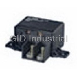
TE CONNECTIVITY 1-1414428-0
Description
Electromechanical Relay 24VDC 141Ohm 150A SPST-NO-DM Flange High Current Relay Automotive
1-1414428-0
Part Number
1-1414428-0
Price
Request Quote
Manufacturer
TE CONNECTIVITY
Lead Time
Request Quote
Category
Relays and I/O Modules » Relay Other
Specifications
Manufacturer
TE Connectivity
Manufacturers Part #
1-1414428-0
Industry Aliases
1-1414428-0
Sub-Category
Other Relays
Brand
P&B
Factory Pack Quantity
50
Datasheet
DDEController?Action=srchrtrv&DocNm=1308028-2_Auto_Relay_Catalog&DocType=CS&DocLang=English&s_cid=1046.pdf
13596 KiB

Extracted Text
00-Cover_1.qxd 17.03.2008 12:00 Uhr Seite 1 RoHS Ready Automotive Relays and Switching Modules 00-Cover_1.qxd 17.03.2008 12:00 Uhr Seite 2 TYCO ELECTRONICS GLOBAL AUTOMOTIVE DIVISION 01_Introduction_p1-34_2.qxd 17.03.2008 12:43 Uhr Seite 1 THE 5 APPLICATION AREAS 1 01_Introduction_p1-34_2.qxd 17.03.2008 12:43 Uhr Seite 2 INNOVATIVE TECHNOLOGIES Tyco Electronics is the world’s largest passive electronic components manufacturer and a world leader in cutting-edge wireless technologies. The company has facilities located in over 50 countries, serving customers in the aerospace, automotive, computer, communications, consumer electronics, industrial and power industries. The global automotive division follows the globalization goals of our customers, speeds up the integration of new technologies and enables our customers access to our vast product portfolio and services. TERMINALS & CONNECTORS Tyco Electronics offers a broad range of high quality terminals and connectors. Our electrical and electronic interconnection products and solutions are used to electrically and mechanically join wires and cables, printed circuit boards, integrated circuit packages and batteries. Our continually expanding capabilities include new copper and fiber-optic connectors, wires, cables and cable management systems that are designed to meet automotive industry demands. The AMP brand encompasses the broadest range of connectors in the world, including high-density, high-speed designs for leading-edge communications equipment. LITERATURE NO. 1308092-2 CABLE ASSEMBLY SYSTEMS Tyco Electronics is your partner for special cable assemblies. Tyco Electronics offers research and development capabilities, prototyping, samples as well as manufacturing facilities for special cable assemblies. This includes overmold technology, semi- and fully-automatic manufacturing, testing equipment and appliances for handling of high volume production. LITERATURE NO. 1654288-2 2 01_Introduction_p1-34_2.qxd 17.03.2008 12:43 Uhr Seite 3 GLOBAL AUTOMOTIVE DIVISION MECHATRONICS A variety of technical products is designed today by integrating mechanical components and electronic hardware into one packaging unit thus creating true mechatronic solutions. Mechatronic applications offer amazing and versatile potentials related to functionality, cost, space requirements and quality. Tyco Electronics contributes to those applications with its wide range of innovative and cost-effective product and process technologies. Advanced stamping, injection molding and assembly techniques are applied along with highly selective surface plating methods. LITERATURE NO. 1308091-2 SENSOR TECHNOLOGY Contactless measuring eliminates interference effects, wear and tear, and provides increased reliability. Tyco Electronics, one of the largest technology providers for the automobile industry, offers contactless sensors for a variety of applications. As sensor manufacturer and processing partner, Tyco Electronics also provides project planning support for new sensor applications, assistance in the selection of the appropriate sensor technology for the respective application, and assistance with defining the corresponding mechanical, electrical and magnetic interface. Tyco Electronics has a broad electromechanical portfolio that includes robust housing technologies, connector systems, and temperature stable designs based on foil and cable networks. This combination of technologies and experience ensures that reliable and cost effective sensor solutions are available for all application types. LITERATURE NO. 1308086-2 RELAYS AND SWITCHING MODULES Automotive technology and integrated systems continue to develop rapidly with electric and electronic systems in today’s vehicles playing an increasingly important role for traffic safety and travelling comfort. Automotive Relays and Switching Modules (AR & SM) of Tyco Electronics’ Global Automotive Division offer a wide range of the most important components for such systems and is the world’s no. 1 player in this industry sector. It is our intent to bring closer to you our total competencies in development, production and related technologies as well as our unique application support thus ensuring the competitive edge for mutual business growth on a worldwide scale. LITERATURE NO. 1308085-2 3 01_Introduction_p1-34_2.qxd 17.03.2008 12:43 Uhr Seite 4 POWER DISTRIBUTION SYSTEMS The extensive net of electrical and electronic loads requires the next evolution of complex powernet structures including intelligent control and distribution systems. Modules with intelligent technology combinations for power distribution units with integrated switching and protection functions together with a maximum of flexibility and modularity at highest package density tuned 100% on customers needs, that’s what Tyco Electronics is working on. LITERATURE NO. 1308087-2 INDUCTIVE SYSTEMS The Global Automotive Division is your source for interconnection and wireless technologies for automotive, truck and off-highway OEMs and Tier 1 suppliers. With the design competency center in Oostkamp (Belgium), and strategic production centers in Evora (Portugal), Bangalore (India), Shenzhen (China), and Oostkamp (Belgium), Tyco Electronics Inductive Systems is ready to offer you any LF-application component required in the automotive branches. The Inductive Systems groups focus is on the customer requirement in order to design to the exact demand. This is achieved by high-technological, intelligent and cost-efficient engineering. In order to be a leader in design, Tyco Electronics Inductive Systems has a vast product portfolio, which consists out of antennas, actuators and integrated modules. Next to that, several specific applications are designed. LITERATURE NO. 1308089-2 ALTERNATIVE POWER SYSTEMS COMPONENTS FOR HYBRID AND FUELCELL TECHNOLOGY Tyco Electronics is a leader in next-generation transportation technologies and products for hybrid and electric vehicles. The Global Automotive Division is your source for high voltage power distribution, high current contacts, high voltage connectors and cables, high voltage relays, sensors and temperature protection devices for hybrid and other alternative powered vehicles. LITERATURE NO. 1308093-2 4 01_Introduction_p1-34_2.qxd 17.03.2008 12:43 Uhr Seite 5 GLOBAL AUTOMOTIVE DIVISION HIGH SPEED DATA NETWORKING High speed data networking within the automobile is becoming more predominant. What was till now restricted to the high end of the ® market utilizing system such as the MOST network, high speed data transmission based on optical fibers, now with the introduction of iPOD’s, display screens and cameras results in the need for high speed networking throughout all platforms. ® MOST IS A TRADEMARK LITERATURE NO. 1308084-2 WIRELESS TECHNOLOGIES RADAR SENSORS & ANTENNAS FOR TELEMATICS Tyco Electronics is a world leading supplier of radar technology for the automotive industries. In cooperation with system integrators and OEMs, Tyco Electronics developed 24 GHz high resolution short range radar sensors in Ultra Wide Band technology and 77 GHz Adaptive Cruise Control radar front ends suitable for driver assistance applications, which enable advanced active and passive safety systems. Tyco Electronics develops, produces and supplies antennas for the automotive industries. Single to Quad band antennas are available in state of the art planar and dipole technologies. All telematic frequency bands for satellite radio, navigation, emergency positioning and cellular mobile communications are covered. LITERATURE NO. 1308090-2 TYCO ELECTRONICS. OUR COMMITMENT. YOUR ADVANTAGE. Tyco Electronics’ businesses operate in thousands of different areas of industry. The products and services we deliver all have one thing in common. They are vital to everyday living. Individuals and companies worldwide have critical needs. And every minute of every day, we satisfy them. 5 01_Introduction_p1-34_2.qxd 17.03.2008 12:43 Uhr Seite 6 TYCO ELECTRONICS “TECHNOLOGY PORTFOLIO” ● Connector Systems/ ● Antennas, GPS Antennas, ● Battery Connectors & Electromechanical Components Integrated Antenna Systems Assemblies ● Relays ● Circuit Protection Devices ● Heat Sinks & Thermal Solutions ● Wireless Products ● Tubing & Harnessing Products ● Switches and Knobs ● Sensors ● Touch Screen Displays ● Identification Labeling Products ● Fiber Optic Products ● Power Systems ● Racks & Panels ● Wire & Cable ● Resistors & Inductors ● Smart Cards/Leadframes ● Application Tooling 6 01_Introduction_p1-34_2.qxd 17.03.2008 12:43 Uhr Seite 7 TYCO ELECTRONICS “AT YOUR SERVICE” Tyco Electronics Online The Tyco Electronics website is an innovative and @ interactive source for application information, product updates and technical solutions. Our step-by-step software makes our website intuitive and user-friendly to better serve you! Please contact us at: www.tycoelectronics.com/automotive Internet Homepage www.tycoelectronics.com www.tycoelectronics.com/automotive Product Information Center (PIC) Electronic Internet Catalog You can rely on Tyco Electronics PIC Team to www.catalog.tycoelectronics.com provide you support for answers to your general information or technical questions in an efficient and effective manner. To reach our PIC staff, please contact your local Tyco Electronics organization. Product and Machine Literature Tyco Electronics offers a variety of product specific catalogs, brochures and high impact flyers to help better serve you! For more information on literature for Tyco Electronics’ Global Automotive Division, please contact your local Tyco Electronics Organization or go to www.tycoelectronics.com/automotive 7 01_Introduction_p1-34_2.qxd 17.03.2008 12:43 Uhr Seite 8 Global Automotive Division Catalog 1308028-2 Revised 3-2008 Automotive Relays and Switching Modules Introduction TYCO ELECTRONICS LTD. AUTOMOTIVE RELAYS AND SWITCHING MODULES Tyco Electronics Ltd. is a leading global provider of Automotive technology has developed at an amazing engineered electronic components, network solutions pace over the past couple of years. Today’s vehicles and wireless systems, to customers in more than feature a multitude of intelligent systems, dramatically 150 countries. We design, manufacture and market increasing all aspects of safety and comfort of driving. products for customers in industries from automotive, Navigation systems with interactive traffic condition appliances and aerospace and defense to telecom- interface have become common even in mid-size cars. munications, computers and consumer electronics. Passive and active safety systems such as antiskid With over 8,000 engineers and worldwide manufac- brake/traction control, belt tensioners, airbags are turing, sales and customer service capabilities, Tyco taken for granted meanwhile. Today, in high-spec cars, Electronics’ commitment is our customers’ advantage. the value of the electric and electronic content More information on Tyco Electronics can be found at reaches almost a quarter of the total vehicle value. www.tycoelectronics.com. The length of the wiring can reach several thousands of meters with as many connection systems between GLOBAL AUTOMOTIVE DIVISION different harnesses, ECU’s and actuators. In all these Tyco Electronics offers a broad range of high quality systems, the reliable switching of lights, motors, electronic component products. We provide solutions heaters, ECU’s has become a function that is critical for OEM applications, utility and energy, outside plant for the overall reliability of the vehicle. Since decades, and premise networking installations and more. Tyco Electronics’ automotive relays have provided Products from well-known brands include connectors the state-of-the-art solution to satisfy the industry’s and interconnection systems, terminal blocks, relays, constantly growing requirements in this area. electronic modules, circuit protection devices, fiber With innovative solutions in design and process and optic components, wires and cables, switches, wireless with completely new features such as latching relays, components, sensors, touch screens and application low noise relays and ultra-miniaturized double relays, tooling. We also provide products to insulate, protect, we provide the switching technology for the latest hold, bundle and identify electrical harnesses. generation of electronic functions in the car. The Star Point Relay – with a triple bridging make contact specially designed to switch the star point of 3-phase motors – represents a key component in the safety concept of electric power steering systems. At the same time, uncompromised quality, based on a strict zero defects philosophy, have become an integral part of all business processes from the first design ideas to mass production. This ensures highest reliability of the electrical systems in the vehicle and for the car owner, customer satisfaction becomes reality. This catalog is intended to give you an overview of our complete range of automotive relays with all relevant technical data. However, as every relay application is different and includes individual requirements, we encourage you to contact your Tyco Electronics representative with your specific application details. For your convenience we have included a questionnaire on page 33 of this catalog. Our team of experienced Application Engineers will be pleased to develop the “made to measure” solution optimized for your needs, and in close cooperation with your experts. 8 All specifications subject to change. Consult Tyco Electronics for latest specifications. 01_Introduction_p1-34_2.qxd 18.03.2008 20:35 Uhr Seite 9 Global Automotive Division Catalog 1308028-2 Revised 3-2008 Automotive Relays and Switching Modules Introduction As a further novelty of this edition the Application Tyco Electronics Relay Experts in our Global Technology Recommendations were extended and are now called Centers and our Application Specialists in Berlin are Application Notes. This section now includes: glad to advise you to find the “made to measure” solution for your automotive applications. – The completely reworked Relay Glossary, – Information on Processing Relays on a PCB, We have also improved our web site; please do not – Details about Automotive Applications, hesitate to visit us at: – Important hints about Diagnostics of Relays, www.tycoelectronics.com – Our revised Application Questionnaire, the address for Tyco Electronics or – An explanation of the V23### Relay Description and – References to our Application Notes in the eCatalog. http://relays.tycoelectronics.com/appnotes/ the address for our Application Notes online or To facilitate the ordering process, the Ordering Information tables display both the V23### Relay http://relays.tycoelectronics.com/telectronics.asp Description and the Tyco Electronics Part Number. the address for our Datasheets or For order processing, only the Tyco Electronics Part Number in the format 1-1234567-1 is relevant, whereas http://catalog.tycoelectronics.com/TE/bin/TE.Connect? V23### Relay Description contains useful information C=15355&M=FEAT&LG=1&I=13 about the relay type in coded form – see explanation the address for our online catalog available to you on page 34. In addition, at the end of the catalog, all 24 hours a day wherever you are. order numbers are listed in a numerical index sorted For further information concerning individual products, according to the Tyco Electronics Part Number giving please contact us in our Worldwide Companies listed an overview and enabling a quick find. at the end of this catalog. Our customer service will The Contact Data contains a minimum recommended be glad to help you. current value for each relay. Should you wish to apply relays below the mentioned current limit please contact our Application Specialists and refer to the Attention new chapter Application Notes (pages 16 ff). www.tycoelectronics.com Furthermore in order to enable a meaningful compari- AMP, AMP SUPERSEAL 1.5 SERIES, AXICOM, son, we completed the Limiting Continuous Current FASTIN-FASTON, TE Logo and Tyco Electronics are given at ambient temperatures of 23°C, 85°C respec- trademarks tively 105°C or 125°C next to the Rated Current values All products shown in this catalog carry the former at 85°C displayed in previous catalogs. logotype Tyco independently of specific customer Further highlights of this issue are: requests. The Overview of Special Featured Products containing This revision replaces all former issues and is the only short form information about relays developed using current valid catalog. This especially applies to special technologies such as Latching and Through- contents and revisions of technical standards and Hole-Reflow (Pin-in-Paste) technology and relays for guidelines referred to in this catalog. special application fields such as 24 V. All specifications subject to change. The AWG Conversion Table that is useful when Consult Tyco Electronics for latest specifications. selecting the right connector for plug-in relays. Tyco Electronics AMP GmbH Paulsternstr. 32 13629 Berlin/Germany Product Information Center Phone: +49-(0)30-38638-775 Fax: +49-(0)30-38638-530 All specifications subject to change. Consult Tyco Electronics for latest specifications. 9 01_Introduction_p1-34_2.qxd 17.03.2008 12:43 Uhr Seite 10 Automotive Relays and Switching Modules Catalog 1308028-2 Revised 3-2008 Table of Contents ■ INTRODUCTION ■ PLUG-IN RELAYS Introduction 8 Micro ISO Relays Table of Contents 10 Micro Relay A 36 Overview Application Areas 12 Micro Relay Latching 42 Application Notes 16 Micro Relay Low Noise 47 – Glossary 16 – Processing Information 25 Mini ISO Relays – Automotive Applications 28 Power Relay F4/VF4 52 – Diagnostics of Relays 31 Shrouded Power Relay F4 A 59 – Application Questionnaire 33 VF4 A (Standard, 64 – Description Explanation 34 Shrouded and Weatherproof) Power Relay B 71 Mini Relay Latching 76 Maxi ISO Relays Power Relay F7/VF7 81 Shrouded Power Relay F7 A 87 Micro 280 Relays VJ28 92 VH28 Half Width 96 Mini 280 Relays VF28 (Standard and Shrouded) 100 ■ PCB RELAYS Single Relays Single Nano Relay (THT – THR) 106 Micro Relay K (THT – THR) 111 Micro Relay K SMD 118 (Standard – Open Vent Hole) Micro Relay K Latching 123 Mini Relay K (Open – Sealed) 128 Power Relay PK2 (THT – THR) 134 Power Relay PK2 Latching 139 Power Relay K (Open – Sealed) 144 Power Relay K-S 151 VKP (Open – Sealed) 156 Twin Relays Nano Relay (THT – THR) 162 Double Micro Relay K (THT – THR) 167 Double Micro Relay K SMD 173 (Standard – Open Vent Hole) Double Mini Relay DMR 178 Axicom Relays for Automotive Applications PCB – Twin Relays IM Relay 183 P2 Relay 184 10 All specifications subject to change. Consult Tyco Electronics for latest specifications. 01_Introduction_p1-34_2.qxd 17.03.2008 12:43 Uhr Seite 11 Automotive Relays and Switching Modules Catalog 1308028-2 Revised 3-2008 Table of Contents ■ HIGH CURRENT SOLUTIONS Latching Relays Micro Relay Latching 239 High Current Devices Mini Relay Latching 239 Star Point Relay SPR 186 Power Relay PK2 Latching 239 High Current Relay 75 190 Micro Relay K Latching 239 High Current Relay 150 194 Battery Disconnect Switch BDS-A 239 Battery Disconnect Switch BDS-A 199 24V Relays Micro Relay A 240 ■ APPLICATION SPECIFIC Power Relay F4/VF4 240 SWITCHING SOLUTIONS Power Relay B 240 Power Relay F7/VF7 240 Basic Module Relays Star Point Relay SPR 241 Power Module Relay F4/F7 and Base 204 High Current Relay 75 241 Application Examples of Power Module 215 High Current Relay 150 241 Relay F4/F7 and Base Battery Disconnect Switch BDS-A 241 Mini Relay K (Open – Sealed) 242 Application Specific Modules Power Relay K (Open – Sealed) 242 Wiper Module 216 Power Relay K-S 242 Cooling Fan Module 217 Power Management Module 218 ■ NUMERICAL INDEX 243 ■ ACCESSORIES ■ GLOBAL CONTACTS 249 Connectors Production Europe Connectors for Micro ISO Relays 226 Connectors for Mini ISO Relays 229 Production North America Connectors for Micro ISO Relays 232 Connectors for Mini ISO Relays 233 Connectors for Mini (Shrouded)/ 234 Maxi ISO Relays Connectors for Mini 280 Relays 235 Annex AWG Conversion Table 236 ■ OVERVIEW SPECIAL FEATURED PRODUCTS Reflow Solderable Relays Single Nano Relay THR 238 Micro Relay K THR 238 Power Relay PK2 THR 238 Nano Relay THR 238 Double Micro Relay K THR 238 All specifications subject to change. Consult Tyco Electronics for latest specifications. 11 01_Introduction_p1-34_2.qxd 17.03.2008 12:43 Uhr Seite 12 TYCO ELECTRONICS GLOBAL AUTOMOTIVE DIVISION Page Plug-In Relays Micro ISO Relays Micro Relay A 36 ✓ Micro Relay Latching 42 ✓ Micro Relay Low Noise 47 ✓ Mini ISO Relays Power Relay F4/VF4 52 ✓ Shrouded Power Relay F4 A 59 ✓ VF4 A (Standard, Shrouded and Weatherproof) 64 ✓ Power Relay B 71 ✓ Mini Relay Latching 76 ✓ Maxi ISO Relays Power Relay F7/VF7 81 ✓ Shrouded Power Relay F7 A 87 ✓ Micro 280 Relays VJ28 92 ✓ VH28 Half Width 96 ✓ Mini 280 Relays ✓ VF28 100 ✓ PCB Relays Single Relays Single Nano Relay (THT – THR) 106 ✓ Micro Relay K (THT – THR) 111 ✓ Micro Relay K SMD (Standard – Open Vent Hole) 118 ✓ Micro Relay K Latching 123 ✓ Mini Relay K (Open – Sealed) 128 ✓ Power Relay PK2 (THT – THR) 134 ✓ Power Relay PK2 Latching 139 ✓ Power Relay K (Open – Sealed) 144 ✓ Power Relay K-S 151 ✓ VKP (Open – Sealed) 156 ✓ 12 01_Introduction_p1-34_2.qxd 17.03.2008 12:43 Uhr Seite 13 THE PRODUCTS ✓✓ ✓ ✓✓ ✓ ✓✓ ✓ ✓✓ ✓ ✓✓ ✓ ✓✓ ✓ ✓✓ ✓ ✓✓ ✓ ✓✓ ✓ ✓✓ ✓ ✓✓ ✓ ✓✓ ✓ ✓✓ ✓ ✓✓ ✓ ✓✓ ✓ ✓✓ ✓ ✓✓ ✓ ✓✓ ✓ ✓✓ ✓ ✓✓ ✓ ✓✓ ✓ ✓✓ ✓ ✓✓ ✓ ✓✓ ✓ 13 01_Introduction_p1-34_2.qxd 17.03.2008 12:43 Uhr Seite 14 TYCO ELECTRONICS GLOBAL AUTOMOTIVE DIVISION Page PCB Relays Twin Relays Nano Relay (THT – THR) 162 ✓ Double Micro Relay K (THT – THR) 167 ✓ Double Micro Relay K SMD (Standard – Open Vent Hole) 173 ✓ Double Mini Relay DMR 178 ✓ Axicom Relays for Automotive Applications/PCB – Twin Relays IM Relay 183 P2 Relay 184 High Current Solutions High Current Devices Star Point Relay SPR 186 ✓ High Current Relay 75 190 ✓ High Current Relay 150 194 ✓ Battery Disconnect Switch BDS-A 199 ✓ Application Specific Switching Solutions Basic Module Relays Power Module F4/F7 and Base 204 ✓ Application Specific Modules Wiper Module 216 ✓ Cooling Fan Module 217 ✓ Power Management Module 218 ✓ Accessories Connectors Production Europe Connectors for Micro ISO Relays 226 ✓ Connectors for Mini ISO Relays 229 ✓ Production Production North America Connectors for Micro ISO Relays 232 ✓ Connectors for Mini ISO Relays 233 ✓ Connectors for Mini (Shrouded)/Maxi ISO Relays 234 ✓ Connectors for Mini 280 Relays 235 ✓ 14 01_Introduction_p1-34_2.qxd 17.03.2008 12:43 Uhr Seite 15 THE PRODUCTS ✓✓ ✓ ✓✓ ✓ ✓✓ ✓ ✓✓ ✓ ✓ ✓ ✓✓ ✓ ✓✓ ✓ ✓✓ ✓ ✓✓ ✓ ✓✓ ✓ ✓✓ ✓ ✓✓ ✓ ✓✓ ✓ ✓✓ ✓ ✓✓ ✓ ✓✓ ✓ ✓✓ ✓ ✓✓ ✓ ✓✓ ✓ 15 01_Introduction_p1-34_2.qxd 17.03.2008 12:43 Uhr Seite 16 Automotive Relays and Switching Modules Catalog 1308028-2 Revised 3-2008 Application Notes Glossary Technical relay terms are used differently. Depending Coil resistance on the relay application and the relay supplier you will Electrical resistance of the energized coil not including face a variety of terms. For this catalog, we preferred a parallel device for → coil suppression. technical terms according to IEC/EN 60 255 Part 1-00. Coil suppression circuit Circuit to reduce the inductive switch off voltage A peak of the relay coil (EMC protection, → switch off voltage peak). Note that most of the circuits reduce Ambient temperature the armature release speed, which can decrease the Temperature in the direct environment of the relay. relay lifetime, especially valid for diodes in parallel Potting can hamper heat transport and consequently to the coil. From the various solutions, the use of a lead to a derating of the relay parameters (e.g. con- Zener diode is particularly suitable (see fig. 1). tinuous current and switching capability). Further information is available on request. Arc Plasma current flow between opening relay contacts. Fig. 1 An arc is enabled by the electric power of the load Class of protection circuit (turn off spark) ionizing the gas between the Ratings for example contacts. The stability of the arc depends on various defined in IEC 529, Relay coil parameters such as → contact material, air pressure, indicating how comple- Switching → contact gap, etc. An arc locally produces high tem- tely a cover, seal, etc. transistor perature causing contact erosion. In cases of strong Break- protects against water, down erosion, → spark suppression becomes necessary. humidity, dust, direct Z-diode contact etc. See also Caution protection class. If a relay that is not especially designed for 42 V applications has to switch off a 42 V load, depending on the conditions (→ contact gap, → load limit curve) Coating an arc of infinite duration could occur. Due to the Protection of → PCB and electrical components by high power consumption in the arc the relay will be applying lacquers on the surfaces. For further details destroyed. please see item 7 in the “Processing Information”. Contact B Made out of → contact material and part of the Bistable relay → contact set where the electrical load circuit is Same as → latching relay. opened or closed. Bounce time Contact carrier The time from the first to the last closing or opening Conductive metal part of the relay where the of a relay contact. → contact is applied to. Break contact, Form B Contact configuration, Form A, B, C → NC contact. The break contact is closed in the Configuration of the relay switch (→ make, → break or → release (rest) state of a → monostable relay and → changeover contact). According to the application, opens (breaks) when the armature moves to the core various contact configurations are used (see table 1). (→ operate state). See also table 1. Contacts which are moved by the armature system are called → movable contacts, and non moving contacts → stationary contacts. C Contact erosion Capacitive load Material loss at the contact surfaces, for example due Switching on a capacitive load results in high inrush to material evaporation by an → arc. current. Lamp loads show similar behavior. Contact force Changeover contact, Form C Force between closed contact surfaces. Contact configuration with → make and → break contact. Changing the switch position opens the Contact gap closed contact first and then closes the formerly open Gap between the contact surfaces of an open contact contact. See also table 1. pair. 16 All specifications subject to change. Consult Tyco Electronics for latest specifications. 01_Introduction_p1-34_2.qxd 17.03.2008 12:43 Uhr Seite 17 Automotive Relays and Switching Modules Catalog 1308028-2 Revised 3-2008 Application Notes Glossary Most Common Contact Configurations Denominations Abbreviations/Symbols Symbol of Form NARM Abbreviation Circuit Element 1) 2) Make contact 1 Form A SPST-NO Double contact make 1 Form A (Double SPST-NO DM (bifurcated) contact make) Break contact 1 Form B SPST-NC Make and break or 1 Form C SPDT Changeover contact Double make 1 Form U SPST-NO DM contact on armature Double break contact 1 Form V SPST-NC DB Double make contact 1 Form X SPST-NO DM Triple make contact Form 3 – 1) 1 Form A 2) Table 1 1 Form A (Double contact make) Contact material The table lists the major contact materials for auto- For relays a variety of contact materials are in use. motive use. As the load rating for a contact depends They operate under a wide range of loads in terms of on the used relay design as well (contact force etc.), voltage and current. Inductive loads can cause high the specification of one relay type cannot simply be switch off voltages and strong → arcs, capacitors transferred to others. create inrush current peaks. Arcs and improper → coil Contact/relay resistance (voltage drop) suppression can reduce the lifetime of a contact. So Electrical resistance between the relay load terminals far, no universal contact material is known, that can while the respective contact is closed. The resistance be used on all load types with optimum performance. can be obtained out of the ratio of the voltage drop Contact manufacturers, relay developers, and users across the relay and the load current (Ohm’s law). have established the following criteria to describe a Surface layers (→ fritting) can result in non-linear contact: contact – resistances and increased voltage drops • Electrical resistance (see chapter Diagnostics of Relays). • Resistance to contact erosion Contact set All contacts in a relay. • Resistance to material transfer • Resistance to welding These criteria can be used to classify the most impor- tant contact materials according to their performance as shown in table 2 on the next page. All specifications subject to change. Consult Tyco Electronics for latest specifications. 17 01_Introduction_p1-34_2.qxd 17.03.2008 12:43 Uhr Seite 18 Automotive Relays and Switching Modules Catalog 1308028-2 Revised 3-2008 Application Notes Glossary Contact Materials Switching function current range Load type inside vehicle Best-suited contact material Switching and carrying currents or In low power applications AgNi0.15 AgSnO 2 0.5 A < I < 10 A at 12 V 6 operations Periodical switching and approx. 10 Long-life indicator switches AgSnO 2 1 A < I < 10 A at ≥ 12 V Switching and carrying of Lamps, Capacitors AgSnO 2 I > 10 A capacitive load Switching and carrying of Motors, Valves AgNi0.15 or AgSnO 2 I > 10 A resistive and inductive load Switching high inrush of Lamp (e.g. H4), Spark plugs, AgSnO in special cases: 2 I > 100 A Short circuit AgNi20 or Tungsten pre-contact Table 2 Cycle time Drop test Sum of make and break (i. e.: on and off) time of a Relays are dropped from a specified height onto a contact pair (fig. 2). solid ground. This simulates the resistance to bad handling e.g. fall from a table. However we recommend 4 t = Make time to scrap dropped relays. Fig. 2 ED t = Cycle time D Z Dry switching U Double break contact, The relay contact switches no or a very small Form V electrical load (< 1 mA, < 100 mV). See also chapter Two break contact Diagnostics of Relays. t configuration, with two t ED Dustproof electrically connected → t Z Covered but non sealed relay, featuring protection movable contacts which class IP54 according to IEC 529 → protection class. t operate simultaneously. ED r = • 100 (%) t See also table 1. Duty cycle Z The ratio between the switch on time and total cycle time during periodical switching (see fig. 2). 50% duty cycle means the switch on time is equal to the switch Double contact off time. Double contact configuration, where two → movable contacts are connected in series and operate simul- taneously. In a bridge configuration, the load current E flows from one → stationary contact via the bridge to Electrical endurance a second stationary contact. See also table 1. Number of load switching operations a relay can Double contact make or bifurcated contact, Form A perform without failure. The lifetime varies with the (Double contact make) load. If not stated otherwise, the reference values Contact type with two contact studs per contact shown in this data book apply for resistive or inductive spring. Both contacts work in parallel. This is used for loads with suitable spark suppression. redundancy and/or reduction of contact resistance. See also table 1. ELV Abbreviation for End-of-Life Vehicles. Double make contact, Form U Environmental endurance Two make contact configuration, with two electrically Generic term for the relay endurance under different connected → movable contacts which operate simul- climatic conditions. Appropriate test conditions are taneously. As special version → main contact with classified in IEC 68. pre-contact. See also table 1. Energization, energizing value Double make contact, Form X A current driven through the relay coil to generate a Two make contact configuration with two electrically magnetic field to move the armature. The energizing connected movable contacts operating simultaneously. value is the product of the coil current and the There is no external connection to the armature. number of wire turns of the coil. 18 All specifications subject to change. Consult Tyco Electronics for latest specifications. 01_Introduction_p1-34_2.qxd 17.03.2008 12:43 Uhr Seite 19 Automotive Relays and Switching Modules Catalog 1308028-2 Revised 3-2008 Application Notes Glossary Industrial atmosphere F Atmosphere carrying dust and certain industrial Faston blade exhaust gases (sulfur, chlorine and nitrogen com- Flat male terminal of a plug-in relay. pounds at certain humidity levels). Faston blade identification numbers for ISO relays J Coil and load faston blades of an ISO relay can be numbered according to two different standards. Jump start However, the terminals have the same location and Short relay use at higher system voltages (like car function. The respective numbers are: start after flat battery). 1 or 86 for the first coil pin; L 2 or 85 for the second coil pin; 3 or 30 for the common load pin; Latching relay 4 or 87a for the NC load pin; In a latching relay, after the coil input voltage is 5 or 87 for the NO load pin. disconnected, the contacts remain in the last reached switching position. Tyco Electronics delivers latching Fritting relays in reset contact position. However in order to See → Icing. eliminate influences due to e.g. transport and pro- Fritting cessing the customer is advised to check the Electrical breakdown which can occur under special set/reset contact position and, if necessary, to conditions (voltage, current) whenever thin contact set/reset the relay into the required position. Latching films prevent electrical conductivity between closed relays only require a short set respectively reset contacts. Fritting is a process which generates impulse. A permanent coil power supply after set- (A-fritting) and/or widens (B-fritting) a conducting ting/resetting the relay is neither necessary nor current path through such a semi-conducting film allowed: maximal pulse durations depend on the relay on a contact surface. During A-fritting, electrons family, for details please refer to the respective are injected into the undamaged film. The electron datasheets. Hence the distinguishing characteristic of current alters the condition of the film producing a monostable relays in respect to a fail safe behavior is “conductive channel”. During the following B-fritting, the fact that the predefined contact rest position will the current widens the channel increasing the conductivity be reached at break down of the power supply. This (R. Holm, Electric Contacts, 4th edition, 1967, Springer- behavior cannot be shown by latching relays due to Verlag, Berlin/Heidelberg/New York). Please also the bistable working principle they are based on. refer to chapter Diagnostics of Relays. Therefore latching relays should not be used in appli- cations that are rated according to ISO/TS 16949 7.5.3 H Product Identification and Traceability. Leadfree H-bridge See chapter Processing Information. The H-bridge or motor-reverse circuit is used to operate a motor in two directions (e.g. door lock, Limiting continuous current steering lock, power window, seat adjustment. The highest current (effective value for AC loads) a See chapter Automotive Applications. relay can carry under specified conditions without exceeding its specified upper limit temperature. I Please note that this is not the current that can be switched with any load over the specified lifetime. Icing Load dump Under very special environmental conditions and Short relay use at overvoltage (disconnection of the temperatures below 0°C temporary relay switching battery during running engine). failures can occur (also defined in the Standard DIN 25424 as “secondary fail”). Moisture condenses on the surface of the cold contact and forms a thin Fig. 3 I layer of ice, causing a temporary interruption of the U electrical contact. Immersion cleanable/sealed relays Relays which are sealed against the penetration of specified → PCB cleaners or lacquers → protection class and refer to chapter Processing Information. Inductive load Life expectancy strongly depends on the inductance of the load circuit. All specifications subject to change. Consult Tyco Electronics for latest specifications. 19 01_Introduction_p1-34_2.qxd 17.03.2008 12:43 Uhr Seite 20 Automotive Relays and Switching Modules Catalog 1308028-2 Revised 3-2008 Application Notes Glossary Load limit curves Maximum operate voltage (or must operate voltage) Switching limit for DC voltage and resistive loads Voltage at → room ambient temperature (RT) a relay (see fig. 3). The load limit curves were measured with must → operate at. To guarantee proper function of low-inductive resistors, verified for 1000 switching all relays, the applied coil voltage in the car must be events. The load limit curves depend on the relay above this specified operating voltage. Please note design (contact gap, contact material, armature that the actual operate voltage of an individual relay, release speed, etc.). → Contact erosion and relay the maximum operate voltage and the car system lifetime vary with different voltage/current values. value are sometimes all called operate voltage. Load limit curve (I) Maximum voltage U or V max max The switch off arc of all NO loads below this load limit Maximum coil voltage at → RT, at which the coil curve extinguishes during the → transit time of the reaches the specified → upper limit temperature with- moving contact. This limit is important for → change out contact load (→ maximum continuous thermal over relays, when the → stationary NC and NO load at 23°C). contacts are at different voltage levels, e. g. in a motor Maximum switching power reverse application. For currents up to 100 A the load Maximum permissible power switched by the relay limit curve has a falling characteristic i. e. for higher contacts, i.e. the product of the switching current currents the voltage drop across the contacts and switching voltage. becomes lower. If a relay that is not especially designed for 24 V or 42 V loads, depending on the Mechanical endurance conditions, (→ contact gap) an arc of infinite duration Number of load free relay switching operations could occur. In a motor reverse circuit the arc will without failure. then shortcut the battery. The current will only be Mechanical stress resistance determined by the resistance of the arc and could rise Characterization of the mechanical stress a relay to several hundreds of Amps. Due to the high power can withstand during installation or use. The stress consumption in the arc the relay will be destroyed. resistance is defined in terms of vibration, shock, Load limit curve (II) drop tests, etc. The switch off arc of the NO loads below this curve Minimum recommended voltage extinguishes within 10 ms (the relay is already in Minimum load voltage to ensure an adequate contact → release position). cleaning (see also “fritting”). Load limit curve for arc-free switching Minimum voltage U or V min min Load voltage/current combinations below this load Minimum coil voltage at → RT where a relay is still limit curve in general cause no arc at all. able to operate. Minimum release voltage (must release voltage) M Voltage at → RT a relay must → release at. Make contact, Form A To guarantee proper function of all relays, the limit in → NO contact. Contact is open in the → release (rest) the car must be below this specified release voltage. state of a → monostable relay and closes (makes) Please note that the release voltage of an individual when the relay coil is energized (→ operate state). relay, the guaranteed minimum (must) release voltage See also table 1. and the car system value are sometimes all called release voltage. Main contact with pre-contact, Form U Double make (Form U) contact with two decoupled Monostable and non polarized relay points of contact on the movable springs. The forward Monostable: Relay which returns to a defined release contact highly resistant to burn-up, e.g. tungsten, state after the coil is de-energized. Non polarized: switches the current. The main contact highly con- the relay coil works independently of the polarity of ductive, e.g. fine grain silver, conducts the current. the applied voltage. The forward contact makes before the main contact Moveable contact does and opens at last. Moving contact during switching operation. Moveable Maximum continuous thermal load at 23°C contact is mounted on the armature/spring system. Maximum coil power consumption of a relay at con- tinuous load operation at room temperature where the relay does not exceed the specified upper limit temperature. 20 All specifications subject to change. Consult Tyco Electronics for latest specifications. 01_Introduction_p1-34_2.qxd 17.03.2008 12:43 Uhr Seite 21 Automotive Relays and Switching Modules Catalog 1308028-2 Revised 3-2008 Application Notes Glossary Operate time N Time from energizing the relay coil till the first break NC contact (normally closed) of the → NC contact or the first make of the → NO → Same as break contact. The break contact is closed contact. See → relay time characteristics, fig. 4. The in the → release (rest) state of a → monostable relay operate time is given as a typical value within each and opens (breaks) when the armature moves to the section “coil data” in this databook. As the coil resis- core (→ operate state). tance depends on the ambient temperature, the operate time varies with the operate voltage and the Nip-off pin ambient temperature. For principal behavior see fig. 5. Removable locking pin of a relay cover ventilation hole. Due to the used plastic materials, an open vent hole is usually not needed for our relays. However, Fig. 5 certain extreme ambient/load conditions can generate noxious gases (diffusion, arc ionization) or over- pressure (during SMD soldering) inside a relay, making a gas exchange with the atmosphere desirable. NO contact (normally open) → Same as make contact. Contact is open in the → release (rest) state of a → monostable relay and closes (makes) when the relay coil is energized (→ operate state). Nominal values (power consumption, voltage) See → rated values. Non-operating current/voltage Overload current Coil current/voltage at which an individual relay does This test is done to make sure, that our relays with- not operate. stand overload conditions, e.g. withstand short circuit Non-release current/voltage conditions until the fuse opens. Current and time are Coil current/voltage at which a → monostable relay compatible to circuit protection by a typical auto- does not release. motive fuse according to ISO 8820-3 (2002) as shown in the table below. Relay will carry the specified currents at 23°C (I = rated current as given in rated O contact data section for each relay). Operate Relay switching process from the release state Test Operating time in seconds (→ NC closed) to the operate state (→ NO closed). Current in A Minimum Maximum Operate state 6.00 *I 0.02 s 0.20 s rated Switch position of an energized → monostable relay. 3.50 *I 0.08 s 0.50 s rated 2.00 *I 0.25 s 5.00 s rated 1.35 *I 0.75 s 1800 s rated Fig. 4 1.10 *I 100 h No requirement rated Table 3 Operate current/voltage/power Coil current/voltage/power at which a relay operates. Operation In tests, a whole switching cycle including energizing and de-energizing of the relay coil. P PCB Common abbreviation for printed circuit board. The times given in this catalog are for 12 V coil voltage PIP and RT, without any devices in parallel to the relay coil. Abbreviation for → pin-in-paste All specifications subject to change. Consult Tyco Electronics for latest specifications. 21 01_Introduction_p1-34_2.qxd 17.03.2008 12:43 Uhr Seite 22 Automotive Relays and Switching Modules Catalog 1308028-2 Revised 3-2008 Application Notes Glossary Pin-in-paste (PIP) Release Insertion technology for → THR components on a Switching process of a relay from the → operate → PCB. The terminals of the component are inserted state (→ NO closed) to the release state (NO opened into printed circuit board holes pre-filled with solder or → NC closed). paste. Release current/voltage Polarity reverse Coil current/voltage at which a → monostable relay See → H-bridge. releases. Please note that the release voltage of an Also see chapter Automotive Applications. individual relay, the guaranteed minimum (must) release voltage of a relay type and the car system Protection class value are sometimes all called release voltage. According to IEC 529 standard following classification can be carried out for our relays. Fig. 6 Class IP67: Our so called “sealed” relays. IP6X: Dust-tight. No ingress of dust. IPX7: Protected against the effects of immersion. Ingress of water in a harmful quantity is not possible when the enclosure is immersed in water under defined conditions of pres- sure and time. Class IP54: Non sealed relays which are protected against flux by their base plate and cover. IP5X: Dust protected. Ingress of dust is not totally prevented, but dust does not enter in suffi- Release state (normal position) cient quantity to interfere with satisfactory Switch position of a → monostable, non energized operation of equipment. relay. IPX4: Protected against splashing water. Water splashed against the enclosure Release time (drop time) from any direction shall have no harmful Time interval between de-energizing the coil of a effect. → monostable relay and the first break of the → NO contact or the first make of the → NC contact. In addition we classify the following types: The release time is given as a typical value within • Flux tight type (open relay without cover) each section “coil data” in this catalog. As the coil resistance depends on the ambient temperature, the • Sealed type open vent hole (on top of cover) release time varies with the ambient temperature. The • Sealed type tight washable influence of the operating voltage can be neglected. • Hermetic type For principal behavior see fig. 8. The release time also depends on → coil suppression circuit. Also refer to Processing Information for → PCB Relays. Reset current/voltage Pull-in voltage Coil current/voltage at which a → latching relay Synonym for operate voltage. switches back to the reset position (generally the same value as for the operating voltage). R RoHS Rated current Abbreviation for Restriction Defined as limiting continuous current at 85°C. RoHS of Hazardous Substances. Ready Rated power Room ambient temperature (RT) Power consumption of the relay coil with → rated coil A standardized value for the resistance at rated voltage and → at room ambient → ambient temperature. In this temperature. data book room ambient temperature means 23°C ±3°C. Rated values (voltage, current, resistance, etc.) Standard values, the relay is designed for. Values are RT used to classify relays. Abbreviation for room ambient temperature. Relay time characteristics Due to the inertia of a magnetic coil and the limited speed of the armature movement, we distinguish various characteristic relay times as shown in fig. 4. 22 All specifications subject to change. Consult Tyco Electronics for latest specifications. 01_Introduction_p1-34_2.qxd 17.03.2008 12:43 Uhr Seite 23 Automotive Relays and Switching Modules Catalog 1308028-2 Revised 3-2008 Application Notes Glossary Storage S Relays should be stored in a clean area within the Sealed relay specified temperature limits. Extreme humidity and Relays which are sealed against the penetration of condensation can cause corrosion of the metal parts specified → PCB cleaners or lacquers → protection in and outside of the relay. Solderability is best within class and refer to chapter Processing Information for a storageperiode of up to 6 months under PCB Relays. 15 to 35°C; 25 to 75% relative humidity, according to IEC 68. SMT relays have to be dried before the Shock resistance soldering process to prevent damage caused by The ability of a relay to operate properly during or evaporating humidity absorbed in the plastic. This after mechanical shock acceleration. is done in the preheating zone of the SMD oven. Silicone atmosphere Temporarily increased contact resistance caused by Silicone and its derivatives are not allowed in the the formation of oxides and other layers during a material of any relay subcomponent. longer storage period, is typical for most contact materials. Materials containing silicone or its derivatives cannot be used in any form in or near to the processing and The growth of such layers depends on the ambient packaging of subcomponents and the final relay atmosphere and is more rapid at high temperature. assembly. Special attention is required if relays are tested or used with low contact loads after extended storage Silicone atmosphere can diffuse through the relay periods. See also “Diagnostics of Relays” in the housing and cause contact failures. Substances Application Notes. containing silicone are for example grease and hand cream. Surface mounted device (SMD) See surface mount technology (SMT). Single contact Contact configuration with a single → stationary/ Surface mounted technology (SMT) → movable contact pair on the make and/or the break An assembly process where electrical connection of side (compare → twin or double contacts). components → (surface mount device) is made to the surface of a conductive pattern of a PCB without Single/double pole (single throw version) component terminal holes. SMT soldering should be A single pole (single throw) relay connects one carried out according to the recommendations of common line (movable contact) to one load line CECC 00802 and IPC/JEDEC J-STD-020C if not (stationary contact). A double pole relay switches two, stated otherwise in the respective datasheet. electrically not connected common lines with two electrically independent load lines (like two separate Switching current make relays). Current switched by the relay contact. Single/double throw (single pole version) Switching rate A single throw (single pole) relay connects one Number of → operations (contact closings and common line (movable contact) to one load line openings) per second. The rated “maximum switching (stationary contact). A double throw (single pole) rate” is measured for load free switching at → room relay switches one common line between two ambient temperature and no → coil suppression → stationary contacts, for example between a device parallel to the coil. → NO contact and a → NC contact (→ changeover Switching voltage relay or form C). Voltage between the relay contacts before closing Spark suppression or after opening the contacts. Reduction of the → arc energy between → movable Switch off voltage peak of the relay coil and → stationary contact during switching. Induced voltage peak caused by the collapsing Stationary contact magnetic field of a de-energizing relay coil. The Non movable contact, mounted on a → contact carrier product of the coil current and the resistance* of the which is directly connected to a relay pin/faston device parallel to the coil approximately gives the blade. amplitude of the switch off voltage. Steady state current limit * In case of a 36 V rated coil the use of a 60 V Varistor or See → limiting continuous current. Zener diode is recommended. All specifications subject to change. Consult Tyco Electronics for latest specifications. 23 01_Introduction_p1-34_2.qxd 17.03.2008 12:43 Uhr Seite 24 Automotive Relays and Switching Modules Catalog 1308028-2 Revised 3-2008 Application Notes Glossary T V Test voltage/dielectric test voltage/dielectric strength Vent hole open (open vent hole) Voltage applied during dielectric (high voltage) tests Reflow solderable relays as well as THR and SMD between intentionally not electrically connected parts relays are provided with an open vent hole on top of of the relay. the cover. Thermal resistance Vibration resistance Relay parameter measured in Kelvin per Watt, which The ability of a relay to maintain the operating state relates the consumed power with the respective during mechanical vibration. temperature increase in thermal equilibrium. Voltage drop/voltage mV drop Without load and parallel resistor, the thermal resist- See → contact/relay resistance. ance of a coil multiplied with its power consumption (at the actual coil temperature) gives the temperature W increase of the coil above ambient temperature. WEEE Through-hole technology (THT) Abbreviation of Waste Electric and Electronic Equipment. An assembly process for mounting components where terminals are passed through supported (plated through) or unsupported (bare) holes in an interconnection substrate. Normally, traditional wave soldering is used with THT components. Through-hole reflow (THR) An assembly process, where THT components are soldered in a reflow process instead of traditional wave soldering. See also → pin-in-paste and for details see chapter Processing Information. Transit time The movement time of the armature after opening of one contact set (e.g. NC) before closing of the other (e.g. NO) of a → changeover relay (→ relay time characteristics, fig. 4). Triple make contact, Form 3 Three make contacts configuration (new form) with three electrically connected movable contacts opera- ting simultaneously. There is no external connection to the armature. See also table 1. 24 All specifications subject to change. Consult Tyco Electronics for latest specifications. 01_Introduction_p1-34_2.qxd 17.03.2008 12:43 Uhr Seite 25 Automotive Relays and Switching Modules Catalog 1308028-2 Revised 3-2008 Application Notes Processing Information Important Facts about 3. Preheating Processing PCB Relays The preheating temperature for drying the flux should not exceed 100°C on top of the PCB. Our relays can be processed in commercial soldering Note: Flux which has not completely dried might and washing installations (if classified as washable). “explode” when immersed in the soldering wave and They cover the following regulations: may get inside an open relay. This could create solder balls generating short circuits on the PCB. Flux tight type relays; open relays without cover: • Solderability according to IEC 68 2-20, Test Ta, 4. Processing on Soldering Lines method 1, aging 3: 4 hours at 155°C, dewetting • Resistance to soldering heat according to • SnPb processing IEC 68 2-20, test Tb, test method 1A Fig. 4.1, 4.2 and 4.3 show the maximum permissible temperatures at the terminals according Sealed type open vent hole relays: to CECC 00802 and IPC/JEDEC J-STD-020C. • Solderability according to IEC 68 2-58; dewetting • Resistance to soldering heat according to IEC 68 2-58 Sealed type washable relays: Fig. 4.1 • Such relays are capable of being automatically 300 soldered and subsequently undergoing a washing ºC Single wave soldering 250 process to remove flux residues without allowing the ingress of flux or washing solvents 200 • Sealing complies to IEC 68 2-17; Test Qc: method 2, the relay will withstand a bubble test at 70°C for 1 min 100 • See also item 6. Chemical Cleaning 0 1. Assembly on the PCB 0 50 100 150 s 200 Time Relays are high precision components that are sensitive to mechanical stress and abusive handling. Care must be taken when handling the relay during Fig. 4.2 all stages of production. Do not exert any pressure 300 on the pins. After assembling the relays onto the ºC Dual wave soldering PCB the relay pins must not be bent for attachment. 250 Bending the pins may affect the relay parameters 1st wave 2nd wave 200 and on immersion the sealing maybe damaged for cleanable relays. If attachment is necessary before soldering, we recommend an external arrangement 100 such as a pressure plate or similar. 2. Fluxing Open and Dustproof Relays 0 0 50 100 150 s 200 Time Fluxer must not penetrate into the relay. It could deposit impurities onto open relays and system failures would occur. When using open or dustproof relays the fluxer should merely touch the bottom of Fig. 4.3 the PCB. It should be set in a way that it cannot flood t L onto the top of the PCB. This is particularly critical if T P Recommended soldering range multilayer PCB are used and there are unused holes 6 K/s max. under the body of the unsealed relay. If there is any doubt about the fluxing process, sealed type wash- Preheating range able or hermetic type relays should be used. Recommended flux (with non corrosive residue): < 8 min type F-SW 32 to 34 to EN 29454-1 (ISO 9454-1). RT 86sp All specifications subject to change. Consult Tyco Electronics for latest specifications. 25 Temperature Temperature 01_Introduction_p1-34_2.qxd 17.03.2008 12:43 Uhr Seite 26 Automotive Relays and Switching Modules Catalog 1308028-2 Revised 3-2008 Application Notes Processing Information For SnPb Eutectic Process we recommend a maximum 6. Chemical Cleaning peak temperature Tp < 225°C. For Pb-free processing In modern PCB assembly, less and less cleaning is we recommend a maximum temperature Tp < 245°C. used. These soldering temperature profiles indicate the Pad/Pin temperature. Note: lf the recommended flux is used, there is no In some cases the ambient temperature may be need to wash the PCB. This helps the environment. greatly increased on top of the relay component. If cleaning is necessary, certain precautions have to In this case the component temperature should not be taken. exceed 260°C. Check for specific mounting conditions. • Flux tight type relays/ In addition the time, parameter t in fig. 4.3, L relays with open vent hole (THR) should be below 150 s. Only the base of the PCB (soldering side) should • Leadfree processing be cleaned to prevent penetration of solvent and The components are ELV/RoHS/WEEE compliant. dissolved flux into the relay. Any other cleaning Processing of relays under leadfree conditions may method involving potential contamination of have impact on relay parameters. We recommend unsealed relays should be avoided. Acidic fluxes that leadfree processes should be carried out using are not suitable for open relays due to the risk of SnAgCu-solder. For further information please refer corrosion, especially inside the coil. to the IPC/JEDEC J-STD-020C. • Sealed type washable/hermetic relays Only sealed relays should be washed carefully to 5. Cooling Post Soldering remove flux residues without allowing the ingress of flux or washing solvents. Nevertheless the PCB After flow soldering, the assemblies should be cooled should be allowed to cool prior to the washing in order to reduce thermal stress and to minimize the process to avoid damaging of the seal due to pressure difference between inside and outside of thermal shock or pressure differential. the relay. Do not cool down by using cold liquids or aerosols. If not performing as prescribed, the relay When using high pressure cleaning processes, sealing could break, cleaning fluid with dissolved flux special care has to be taken to avoid any ingress into might be sucked inside the relay. Ingress of liquids the relay. Liquids under high pressure can damage into the relay can lead to failures in operation. the seal of the relay. Modern cleaning equipment uses water or alkaline solutions, which are more environment-friendly than chlorofluorocarbons (CFC). If other cleaning solvents are used, ensure that the chemicals are suitable for the relay. The use of unsuitable solvents can cause cracking or discoloring of the plastic parts. Suitable solvents include isopropyl alcohol (alcohol-based solvents), water with wetting agents. Unsuitable solvents are e.g. acetone, ethyl acetate, aqueous alkalines, phenolic combinations, thinner-based solvents, chlorosenebased solvents, trichlene-based solvents and chlorine. Fluor-based cleaning solvents like Freon are prohibited nowadays. 26 All specifications subject to change. Consult Tyco Electronics for latest specifications. 01_Introduction_p1-34_2.qxd 17.03.2008 16:06 Uhr Seite 27 Automotive Relays and Switching Modules Catalog 1308028-2 Revised 3-2008 Application Notes Processing Information 7. Protective Coating 9. Silicone of Assembled PCB Silicone and its derivatives are not allowed in the material of any relay subcomponent. Materials Do not coat flux type relays. Sealed type open vent containing silicone or its derivatives cannot be used hole could only be partly coated. in any form in or near to the processing and pack- For varnishing of assembled PCB, we recommend aging of subcomponents and the final relay assembly. one-component lacquers (epoxy-based). If using a Contamination can occur with polyurethane based lacquer, check if the solvent damages the relay. • Volatile silicones • Silicone aerosols We recommend the usage of a selective coating technology to make sure that the area between relay • Silicone fluids bottom and board is free of lacquer. The volatility of silicone materials depends on If not possible, make sure that the varnish is cured temperature, molecular weight and structure. Arcing, under constant or increasing process temperature. i.e. by switching relays or rotating motors, degrades The coating lacquer temperature should not be lower silicone species into siliceous compounds that than the relay temperature. deposit as an insulating abrasive layer on the contact surface. This layer generates either contact resistance A further possibility is to mount the relay after coating. increase in relays or failure in electrical motors due Do not allow de-varnishing of PCB for repair. to abrasion of the collector. It must be pointed out If unavoidable the relay has to be replaced in addition that all silicone-based materials before and after cure by a new one. have a certain percentage of silicone volatiles. We recommend a drying oven temperature of 70°C. In standard materials, this varies from 0.5 to 3%, but The temperature should not exceed the maximum it can be even more in some very low viscosity con- temperature range specified in the datasheets. formal coatings (“The use of silicon materials in close proximity of electrical motors and mechanical relays”; 8. Hand Soldering e-Drive Magazine Dec. 2005/Jan. 2006; Vol. 6, Is. 6). In addition silicone aerosols and volatile silicones For hand soldering please refer to the following can diffuse through the relay housing. Substances standard: ANSI/J-STD-001. containing silicone are for example grease and hand Temperature of soldering iron 300 to 350°C. cream. Soldering time < 2 s. All specifications subject to change. Consult Tyco Electronics for latest specifications. 27 01_Introduction_p1-34_2.qxd 17.03.2008 12:43 Uhr Seite 28 Automotive Relays and Switching Modules Catalog 1308028-2 Revised 3-2008 Application Notes Automotive Applications Typical Automotive Applications Load Application examples Typical current curve Resistive Loads - Heatings (rear window heating, seat heating glow plug, air/water preheating) time Capacitive Loads - Lamps (front and rear beam, fog lights, flasher) - Filter capacitors in electronic modules (engine management module, ABS module) time Inductive Loads - Solenoids (vales, clutches, relay coils) Motor - Motors and pumps Solenoid (power window, central lock, cooling fan) time Table 1 Introduction Ubatt Relay The range of applications can be classified into resistive loads, capacitive loads and inductive loads. The current curve of resistive loads is specified by the load voltage and load resistance. Capacitive loads have a high inrush current and a low steady current. Therefore lamps are counted to the capacitive loads, because the cold filament has a significantly lower resistance, than the hot filament. Inductive loads are characterized by an exponential current increase Fig. 1 Short-circuit brake and a remarkable switch off arc, induced by the demagnetization of the magnetic circuit of the load. Motor-Reverse Circuit (H-Bridge) Power supply relays (clamp relays) can switch or feed a mixture of different loads. The H-bridge is used to operate a motor in two direc- tions (e.g. door lock, steering lock, power window, The circuit design of resistive and capacitive loads is seat adjustment, etc.). The operation time is typically usually a simple switch on and switch off. Motor load very short compared to the thermal time constant of circuits are often more complex. The most typical the relay (e.g. door lock < 1 s, power window < 10 s). circuits are described hereafter. This means, H-bridge relays must be designed for high current-switching-capability, but not for high Short-Circuit Brake current-carrying-capability. Higher load voltages can be critical, due to possible short-circuit-arcs (see also The short-circuit brake is used, wherever an electric short-circuit brake). motor must be braked (e.g. wiper). The short-circuit Ubatt brake transforms the rotational energy of the motor into electrical energy. The short-circuit brake can be Relay Relay critical at higher load voltages. If the switch-off arc turn right turn left does not extinguish during the transition time of the movable contact, the arc creates a direct shortage of the power source. Particularly in 24 V systems, the resulting extremely high arc current could cause almost instantly severe damage to the contacts and could destroy the entire relay. Fig. 2 H-bridge 28 All specifications subject to change. Consult Tyco Electronics for latest specifications. current current current 01_Introduction_p1-34_2.qxd 17.03.2008 12:43 Uhr Seite 29 Automotive Relays and Switching Modules Catalog 1308028-2 Revised 3-2008 Application Notes Automotive Applications Wiper Circuits Cooling Fan Circuits To stop the wiper in the correct position, a short-circuit Depending on the size of the engine, either one or two brake is used. This can be done either by an internal fans are used to cool the engine. There are different slipring (usually used for rear wiper) or with the possibilities to control the speed of the fans. Single normally closed contact of the relay (usually used for fan systems are usually controlled by one or more front wiper). This requires a high switching capability serial resistors. The disadvantage is the electrical of the N/C-contact, especially in combination with power loss of the resistors. Double fan systems are intermittent wipe function or rain sensor control. normally controlled by switching them either in series Dual speed wipers have two windings, which are (low speed) or in parallel (high speed). If more commuted by a second relay. There are also wiper speed steps are needed, additional serial resistors systems without mechanical gear, which are electrically are used. reversed with a H-bridge circuit. A more sophisticated method is a PWM-controlled brushless motor. In commercial vehicles the cooling fan is mostly driven directly by the motor shaft. Ubatt Ubatt Relay Relay Relay on/off highspeed lowspeed R slipring Fig. 3 Standard front slipring Fig. 5 Single fan circuit Ubatt Ubatt Relay Relay highspeed on/off Relay Relay highspeed Relay high/low lowspeed Fig. 4 Wiper with internal wiper-circuit Fig. 6 Double fan circuit All specifications subject to change. Consult Tyco Electronics for latest specifications. 29 01_Introduction_p1-34_2.qxd 17.03.2008 12:43 Uhr Seite 30 Automotive Relays and Switching Modules Catalog 1308028-2 Revised 3-2008 Application Notes Automotive Applications Coil Suppression Circuits The disconnection of the relay coil generates a The best protection method for the driver is a diode transient voltage peak, which is only limited by the in parallel to the relay coil. But this method has the parasitic inductivity and capacity of the electrical worst influence on lifetime of the relay. Typical system. In most of the cases it is necessary to suppress suppression methods are a resistor in parallel to the the transient voltage peak to typically 60 V – 100 V coil (preferably as internal component in plug-in for the protection of the relay driver or the vehicle relays) or a Zener diode in parallel to the relay driver electrical system. Any voltage suppression of the (preferably for PCB relays). relay coil influences the dynamics of the electro- mechanical system and can reduce the lifetime. Suppression in parallel to relay coil Suppression (external or internal) in parallel to driver Ubatt Ubatt Ubatt R D Z-Diode Fig. 7 Coil suppression circuits Micro ISO Plug-In Relay ISO Micro Plug-in relay 100 80 60 Lampload 40 220W 20 Motorload 20A, 1mH 0 (Rpar = 6 x Rcoil) Without Z-Diode Resistor Diode Suppression method Fig. 8 Influence of coil suppression on the lifetime 30 All specifications subject to change. Consult Tyco Electronics for latest specifications. Relative lifetime [%] 01_Introduction_p1-34_2.qxd 17.03.2008 12:43 Uhr Seite 31 Automotive Relays and Switching Modules Catalog 1308028-2 Revised 3-2008 Application Notes Diagnostics of Relays The breakdown voltage depends on the thickness Introduction and specific resistance of the layer and can reach With the increase of electronic circuits and safety theoretically some hundred volts. In the practice of requirements in cars, more and more switching con- automotive relays the breakdown voltage can be up tacts are monitored by diagnostic routines. to 3 V. A current of min. 10 mA is needed to start the Similar routines are used by the system suppliers A-fritting. before, during and after the assembly processes After the electrical breakdown a small current is (In-Circuit and End-Of-Line tests) as well. forced through very thin channels in the layer. The Automotive relays are originally designed to switch resulting local high current density heats the con- real automotive applications (e.g. motors, lights, ducting channels up quickly, destroying the layers, heating, etc.) with a load voltage of 12 V (or 24 V or until finally (within a few ms) a metal to metal bridge 42 V) and load currents above 1 A. Lower diagnostic is established. This process is called B-fritting. The current and voltage levels can result in wrong B-fritting voltage depends again on the thickness and interpretations of the state of the relay contact. specific resistance of the layer and can reach in the practice of automotive relays up to 300 mV. This paper explains the technical background of the relay contact system, coil system and dynamic behavior and gives recommendations for applicable diagnostic routines. Contact System The most common contact materials for automotive relays are fine grain silver (AgNi0.15) and silver tin oxide (AgSnO ). Both materials are affected by 2 sulfidation and oxidation. These layers of oxides, sulfides and other compounds will be formed on the surface of metal-contacts by absorption of gas molecules from the ambient atmosphere within a very short time. The layers will increase the contact resistance. The resistance of such layers depends on the thickness of the layer, effective contact area and the specific resistance of the contact material/layer. Fig. 2 Fritting of a relay contact To get a reliable electric contact these layers have to be destroyed. This can be done by mechanical, electrical or thermal destruction. A thermal destruction requires high temperatures, A mechanical destruction requires high contact which will only be generated by high contact currents forces. With the very high degree of miniaturization or electric arcs (disconnecting inductive loads). The of automotive relays, those contact forces cannot thermal destruction can only take place, after an be safely achieved, especially for normally-closed electrical destruction. contacts. Coil System and Dynamic Behavior An electrical destruction requires a specific break- down voltage and current. This destruction process Automotive relay coils are designed for DC-voltages. is called A-fritting. The switching times (i.e. operate time or switch-on time and release time or switch-off time) are usually in the low millisecond-range. The operate time depends on the applied coil voltage. Fig. 3 shows the relation of the operate time and coil voltage, related to the actual pull-in voltage. The nominal voltage in the displayed case is 170% of the actual pull-in voltage at an ambient temperature of 23°C (e.g. 7 V pull-in voltage at 12 V nominal voltage). Higher coil tempera- tures increase the pull-in voltage and subsequently increase the operate time at the same applied coil voltage. Including possible contact bouncing, the operate time can be three times as high as the typical values shown in the datasheets. Fig. 1 Contact layers All specifications subject to change. Consult Tyco Electronics for latest specifications. 31 01_Introduction_p1-34_2.qxd 17.03.2008 12:43 Uhr Seite 32 Automotive Relays and Switching Modules Catalog 1308028-2 Revision 03-2008 Application Notes Diagnostics of Relays Recommendations for Diagnostic Routines A contact diagnostic routine must: Take into account, that the contact resistance may be non-linear. Due to the explained fritting phenome- na, the contact resistance can be non-linear. This means, that the contact resistance, measured at low voltage and current levels (e.g. standard multimeter) can be significantly higher than the contact resistance under real conditions (e.g. supplying a 100 W load). We recommend to perform the diagnostic routine with the real application and real board net voltage connected. Fig. 3 Operate time Supply a sufficient voltage and current to force the A-fritting. If the diagnostic routine cannot be performed with real application and voltage, the measurement The release time depends mainly only on the used voltage level must secure an electrical breakdown of coil suppression. A low ohmic device (e.g. a diode) in possible layers. We recommend a voltage level of parallel to the relay coil can increase the release time min. 5 V and current of min. 100 mA. by a factor of up to 4 compared to the typical values shown in the datasheets. Accept, that the voltage drop can be 300 mV. The B-fritting is a physical phenomenon, which can occur on all silver based contacts. For signal-applications, special signal relays are available. We recommend to set the diagnostic threshold voltage to 500 mV per relay contact (important for H-bridges or serial contact arrangements). Regard the maximum possible switching times. If the status of the contact has to be changed for the diagnostic routine (energize or de-energize relay), the routine must wait until the intended contact status is reached. Depending on ambient conditions (tem- perature, voltage levels, coil circuits) the times can be significantly longer than the specified typical times. Fig. 4 Release time We recommend a delay time of min. 10 times of the typical switching times. Coil Resistance The inductivity of automotive relay coils can exceed A coil diagnostic routine must: (in the unsaturated range) 1 H. This results in time constants tau between 1 to 50 ms for the exponential Secure, that the status of the contact does not change inductive current increase (jump response). If the during the diagnostic. If the coil driver is monitored ohmic coil resistance is measured with a 4-pole by a watchdog routine, the energizing/de-energizing measurement, the resistance value will be wrong, if time of the coil must not result in an unintended it is measured during the inductive current increase closing or opening of the contacts. We recommend after switch on. times of max. 0.5 ms. Remarks 1. During the lifetime of the car, the relay parameters can alter due to ageing processes like contact erosion, fretting corrosion and relaxation. Moreover the environmental requirements (temperature, vibration etc.) in the car are higher than in IC- or EOL-tests. Therefore we recommend for diagnostic routines in the car a higher threshold voltage (approx. 3 V) and higher delay times (min. 15 times of the typical switching times). 2. Most of the applications, switched by relays, are not safety related. If a potential relay failure is detected, we recommend to not block any further activation of the relay but to write the occurrence into the error memory. 32 All specifications subject to change. Consult Tyco Electronics for latest specifications. 01_Introduction_p1-34_2.qxd 17.03.2008 12:43 Uhr Seite 33 Automotive Relays and Switching Modules Catalog 1308028-2 Revised 3-2008 Application Notes Application Questionnaire To ensure the selection of the best suitable relay type for your application, we strongly recommend to complete below questionnaire and consult your local Tyco Electronics representative or our application support. Company: Name: Department: Address: Phone: Email: 1. General Information Application: ___________________________ Relay type: _________________________________ ___________________________ Contact arrangement: NC ❑ NO ❑ C/O ❑ 2. Wiring Diagram/Sketch (Please use separate sheet if needed) 3. Driving (Control) Circuit Minimum coil resistance (23°C) _____ Ω Vehicle electrical system: 12 V ❑ 24 V ❑ other: ___ V 1) Pull-in voltage at 23°C _____ V Further requirements for operate and release voltage: 1) Pull-in voltage at max. temperature _____ V _____________________________________________ Maximum vehicle voltage _____ V _____________________________________________ 1) Coil temperature Duty cycle Energized time: __________s De-energized time: __________s Ambient temp. range Minimum: __________°C Maximum: __________°C Relay coil suppression None ❑ Parallel resistor ❑ Diode type ❑ Others ❑ 4. Load Description Inductive load ❑ _____ mH Resistive load ❑ Lamp load ❑ Others ❑ (detailed description please) N/O (make contact) Max. make current ___ A Max. break current ___ A Max. cont. current ___ A N/C (break contact) Max. make current ___ A Max. break current ___ A Max. cont. current ___ A 2) 2) Dry Switching (currents < 1 A) Yes ❑ No ❑ Unknown ❑ 2) 2) Switching status diagnostics intended Yes ❑ No ❑ Unknown ❑ 2) Contact Tyco Electronics representative for important guidelines about dry switching and diagnostic routines. Spark suppression components ____________________________ Required number of switching cycles ____________________________ 5. Miscellaneous Dimensions in mm L ______ W ______ H ______ Footprint _______________ Approvals _______________________________________________________ Others _______________________________________________________ _______________________________________________________ _______________________________________________________ 6. Quantity Volume in 1st year 2nd year 3rd year 4th year Pieces All specifications subject to change. Consult Tyco Electronics for latest specifications. 33 01_Introduction_p1-34_2.qxd 17.03.2008 12:43 Uhr Seite 34 Automotive Relays and Switching Modules Catalog 1308028-2 Revised 3-2008 Application Notes Description Explanation V 2 3 # # # - # # # # - # # # * * Product designator Product family designator Product type designator Coil designator Specific product design X = customer specific : Numerical # : Letter Contact material and arrangement. If previous * index is X = customer specific identifier Example Relay Description V23072-A1061-A303 V23086-C1021-A502 Relay Family Mini Relay K Micro Relay K Relay Type Open version Sealed version Coil Designator 12 V 12 V Design Standard version Standard version Contact Material and Arrangement AgNi0.15, CO AgSnO , NO 2 34 All specifications subject to change. Consult Tyco Electronics for latest specifications. 02-Plug-in_Relays_p_35-104_1.qxd 17.03.2008 15:31 Uhr Seite 35 Plug-In Relays Catalog 1308028-2 Revised 3-2008 Technical Information Page Micro ISO Relays Micro Relay A 36 Micro Relay Latching 42 Micro Relay Low Noise 47 Mini ISO Relays Power Relay F4/VF4 52 Shrouded Power Relay F4 A 59 VF4 A (Standard, Shrouded and Weatherproof) 64 Power Relay B 71 Mini Relay Latching 76 Maxi ISO Relays Power Relay F7/VF7 81 Shrouded Power Relay F7 A 87 Micro 280 Relays VJ28 92 VH28 Half Width 96 Mini 280 Relays VF28 (Standard and Shrouded) 100 All specifications subject to change. Consult Tyco Electronics for latest specifications. 35 02-Plug-in_Relays_p_35-104_1.qxd 17.03.2008 15:31 Uhr Seite 36 Plug-In Relays Catalog 1308028-2 Revised 3-2008 Micro ISO Relays Micro Relay A Features – Limiting continuous current 25 A at 85°C – High current version with limiting continuous current 30 A at 85°C – Pin assignment according to ISO 7588 part 3 Customized Versions on Request – 24 V versions with special contact gap – Integrated components (e.g. diode) – Customized marking – Special covers (e.g. notches, release features, brackets) – For latching version refer to Micro Relay Latching – For low noise version refer to Micro Relay Low Noise – For high current version refer to Ordering Information page 41 Typical Applications Cross carline up to 25 A for example: – ABS control – Blower fans 074_3D03 – Cooling fan – Door control – Door lock Design Terminals Conditions – Fuel pump – ELV/RoHS/WEEE compliant Quick connect terminals similar to All parametric, environmental and – Heated front screen – Dustproof; protection class IP54 ISO 8092-1, coil and break 4.8 x 0.8 mm, endurance tests are performed – Immobilizer to IEC 529 (EN 60 529) load 6.3 x 0.8 mm; surfaces tin plated according to EIA Standard RS-407-A – Interior lights at standard test conditions unless – Seat control Weight Accessories otherwise noted: – Seatbelt pretensioner Approx. 16 – 20 g (0.5 – 0.7 oz.) Connectors see page 226 ff 23°C ambient temperature, – Sun roof 20 - 50% RH, 998.9 ±33.9 hPa. – Trunk lock Nominal Voltage – Valves 12 V or 24 V For general storage and processing – Window lifter recommendations please refer to our – Wiper control Application Notes and especially to Storage in the “Glossary” page 23 or Please contact Tyco Electronics at http://relays.tycoelectronics.com/ for relay application support. appnotes/ Disclaimer All technical performance data apply to the relay as such, specific conditions of the individual application are not considered. Please always check the suitability of the relay for your intended purpose. We do not assume any responsibility or liability for not complying herewith. We recommend to complete our questionnaire and to request our technical service. Any responsibility for the application of the product remains with the customer only. All specifications are subject to change without notification. All rights of Tyco Electronics are reserved. 36 All specifications subject to change. Consult Tyco Electronics for latest specifications. 02-Plug-in_Relays_p_35-104_1.qxd 17.03.2008 15:31 Uhr Seite 37 Plug-In Relays Catalog 1308028-2 Revised 3-2008 Micro ISO Relays Micro Relay A Dimensional Drawing 23 max 15.5 max 25.4 max 24.1 ±0.2 Measurement reference plane 5x 11.2 ±0.3 0.2 0.8 ±0.05 4.8 ±0.1 6.3 ±0.1 Quick connect terminal similar to ISO 8092-1 Quick connect terminal similar to ISO 8092-1 View of the Terminals (bottom view) 11.4 ±0.2 4.5 ± 0.15 1 7.65 ±0.2 3 5 4 4.5 ± 0.15 2 W_L_E_WMF 8 ± 0.15 6 ± 0.15 Positional tolerances 0.15 Cover Marking 3 ± 0.1 3 ± 0.1 W_K_L_WMF Cover markings: Color coding Sorting feature Only available for Micro Relay A on request All specifications subject to change. Consult Tyco Electronics for latest specifications. 37 02-Plug-in_Relays_p_35-104_1.qxd 17.03.2008 15:31 Uhr Seite 38 Plug-In Relays Catalog 1308028-2 Revised 3-2008 Micro ISO Relays Micro Relay A Contact Data Contact configuration 1 Make contact/ 1 Changeover contact/ 1 Form A 1 Form C Circuit symbol Rated voltage 12 V 24 V 12 V 24 V Rated current Standard High current 25 A 30 A 15 A 15/25 A 10/15 A Limiting continuous current NC/NO 23°C 30 A 35 A 30 A 20/30 A 85°C 25 A 30 A 25 A 15/25 A 125°C 10 A 15 A 10 A 8/10 A Contact material Silver based Max. switching voltage/power See load limit curve 1) Max. switching current NC/NO NC/NO 2) On 120 A 120 A 120 A 40/120 A 20/120 A Off 30 A 30 A 20 A 15/30 A 10/20 A 3) Min. recommended load 1 A at 5 V Voltage drop at 10 A (initial) NO contact Typ. 15 mV, 200 mV max. Typ. 15 mV, 200 mV max. NC contact Typ. 20 mV, 250 mV max. 7 Mechanical endurance (without load) Typ. 10 operations 5 5 5 5 Electrical endurance > 1 x 10 operations > 1 x 10 operations > 1 x 10 operations > 1 x 10 operations (example of resistive load, 25 A, 14 V 30 A, 14 V 15 A, 28 V 25 A, 14 V 15 A, 28 V further information on request) (NO contact) (NO contact) 5 > 1 x 10 operations 10 A, 28 V (NC contact) Max. switching rate at nominal load 6 operations per minute (0.1 Hz) 1) The values apply to a resistive or inductive load with suitable spark suppression and at maximum 13.5 V for 12 V or 27 V for 24 V load voltages. 2) For a load current duration of maximum 3 s for a make/break ratio of 1:10. 3) See chapter Diagnostics of Relays in our Application Notes page 31 or consult the internet at http://relays.tycoelectronics.com/appnotes/ Load Limit Curve ^ Load limit curve 1 = arc extinguishes, during transit time (changeover contact) ^ Load limit curve 2 = safe shutdown, no stationary arc (make contact) 38 All specifications subject to change. Consult Tyco Electronics for latest specifications. 02-Plug-in_Relays_p_35-104_1.qxd 17.03.2008 15:31 Uhr Seite 39 Plug-In Relays Catalog 1308028-2 Revised 3-2008 Micro ISO Relays Micro Relay A Circuit Diagram AR CR 1 Make contact/1 Form A 1 Changeover contact/1 Form C with Resistor with Resistor 2 5 2 54 1 3 1 3 Coil Data Available for nominal voltages 12 V / 24 V Nominal power consumption at nominal voltage with suppression resistor Micro A 12 V Micro A 12 V high current Micro A 24 V 1.4 W 1.1 W 1.6 W Test voltage winding/contact 500 VACrms Ambient temperature range –40 to +125°C Max. switching rate without contact loading 20 Hz Operate time at nominal voltage Typ. 5 ms Release time at nominal voltage Typ. 3 ms Note: A low resistive suppression device in parallel to the relay coil increases the release time and reduces the lifetime caused by increased erosion and/or higher risk of contact tack welding. Operating Voltage Range TE074_OVR1 Does not take into account the temperature rise due to the contact current E = pre-energization All specifications subject to change. Consult Tyco Electronics for latest specifications. 39 02-Plug-in_Relays_p_35-104_1.qxd 17.03.2008 15:31 Uhr Seite 40 Plug-In Relays Catalog 1308028-2 Revised 3-2008 Micro ISO Relays Micro Relay A Mechanical Data Cover retention Axial force 150 N Pull force 150 N Push force 200 N Terminals Pull force 100 N Push force 100 N 1) Resistance to bending, force applied to front 10 N 1) Resistance to bending, force applied to side 10 N Torsion 0.3 Nm Enclosures Dust cover Protects relay from dust. For use in passenger compartment or enclosures. 1) Values apply 2 mm from the end of the terminal. When the force is removed, the terminal must not have moved by more than 0.3 mm. Environmental Conditions Temperature range, storage Refer to Storage in the “Glossary” catalog page 23 or http://relays.tycoelectronics.com/appnotes/ Test Relevant standard Testing as per Dimension Comments Climatic cycling with condensation EN ISO 6988 6 cycles Storage 8/16 h Temperature cycling IEC 68-2-14 Nb 10 cycles –40/+85°C (5°C per min) Damp heat cyclic IEC 68-2-30 Db, Variant 1 6 cycles Upper air temperature 55°C constant IEC 68-2-3 Ca 56 days 3 3 Corrosive gas IEC 68-2-42 10 ±2 cm /m SO2 10 days 3 3 IEC 68-2-43 1 ±0.3 cm /m H2S 10 days Vibration resistance IEC 68-2-6 (sine sweep) 10 - 500 Hz No change in the min. 5 g switching state > 10 μs Shock resistance IEC 68-2-27 (half sine form single pulses) min. 20 g Valid for NC contacts, 11 ms NO contact values significantly higher Load dump ISO 7637-1 (12 V) Test pulse 5 Vs = +86.5 V ISO 7637-2 (24 V) Test pulse 5 Vs = +200 V Jump start 24 V for 5 minutes conducting nominal current at 23°C Drop test Capable of meeting specifications after 1.0 m (3.28 ft) drop onto concrete 1) Flammability UL94-HB or better (meets FMVSS 302) 2) Overload current 34 A, 1800 s 50 A, 5 s 87.5 A, 0.5 s 150 A, 0.1 s 1) FMVSS: Federal Motor Vehicle Safety Standard. 2) Current and time are compatible with circuit protection by a typical 25 A automotive fuse. Relay will make, carry and break the specified current. 40 All specifications subject to change. Consult Tyco Electronics for latest specifications. 02-Plug-in_Relays_p_35-104_1.qxd 17.03.2008 15:31 Uhr Seite 41 Plug-In Relays Catalog 1308028-2 Revised 3-2008 Micro ISO Relays Micro Relay A Ordering Information Part Numbers (see table below for coil data) Circuit/Contact Contact Enclosure Coil Terminals Relay Description Equivalent to Part Number Arrangement Material Suppression 1) 12 V Plug-In Relays V23074-A1001-A402 VFM-11F41-S01 0-1393292-5 AR/1 Form A AgSnO2 Dust cover Resistor 680 Ω Quick connect V23074-A1001-A403 VFM-15F41-S01 8-1393292-4 CR/1 Form C AgSnO2 Dust cover Resistor 680 Ω Quick connect 1) High current version V23074-H1005-A502 2-1414971-4 AR/1 Form A AgSnO2 Dust cover Resistor 680 Ω Quick connect 1) 24 V Plug-In Relays V23074-A1002-A402 AR/1 Form A AgSnO2 Dust cover Resistor 1800 Ω Quick connect V23074-A1002-A403 CR/1 Form C AgSnO2 Dust cover Resistor 1800 Ω Quick connect 1) Versions with diode or varistor in parallel to the coil on request. Versions with special labels or color shapes on request Coil Versions Coil Data Coil Must Must 2) 1) for Rated Coil Resistance Operate Release Allowable Overdrive Micro A Voltage ±10% Voltage Voltage Voltage (V) Ω (with Resistor) (V) ( ) (V) (V) at 23°C at 85°C V23074-**001-**** 12 105 7.2 1.6 24 18 V23074-**002-**** 24 354 14.4 3.6 45 33 V23074-**005-**** 12 127 7.2 1.6 24 18 1) Allowable overdrive is stated with no load applied and minimum coil resistance. 2) Including parallel resistor. Standard Delivery Packs (orders in multiples of delivery pack) Micro A: 480 pieces All specifications subject to change. Consult Tyco Electronics for latest specifications. 41 02-Plug-in_Relays_p_35-104_1.qxd 17.03.2008 15:31 Uhr Seite 42 Plug-In Relays Catalog 1308028-2 Revised 3-2008 Micro ISO Relays Micro Relay Latching Features – Magnetically latched ISO plug-in relay – Two coils with set and reset function – Pin assignment according to ISO 7588 part 3 – Plug-in terminals Customized Versions on Request – Special marking – Special covers (e.g. notches, release features, brackets) Typical Applications – Active power management – Disconnection of power outlets – Security systems Please contact Tyco Electronics for relay application support. 145L_3D2 Design Terminals Conditions – ELV/RoHS/WEEE compliant Quick connect terminals similar to All parametric, environmental and – Dustproof; protection class IP54 ISO 8092-1, coil and break 4.8 x 0.8 mm, endurance tests are performed to IEC 529 (EN 60 529) load terminals 6.3 x 0.8 mm; according to EIA Standard RS-407-A surfaces tin plated at standard test conditions unless Weight otherwise noted: Accessories Approx. 15 g (0.5 oz.) 23°C ambient temperature, Connectors see page 226 ff 20 - 50% RH, 998.9 ±33.9 hPa. Nominal Voltage 12 V For general storage and processing recommendations please refer to our Application Notes and especially to Storage in the “Glossary” page 23 or at http://relays.tycoelectronics.com/ appnotes/ Disclaimer All technical performance data apply to the relay as such, specific conditions of the individual application are not considered. Please always check the suitability of the relay for your intended purpose. We do not assume any responsibility or liability for not complying herewith. We recommend to complete our questionnaire and to request our technical service. Any responsibility for the application of the product remains with the customer only. All specifications are subject to change without notification. All rights of Tyco Electronics are reserved. 42 All specifications subject to change. Consult Tyco Electronics for latest specifications. 02-Plug-in_Relays_p_35-104_1.qxd 17.03.2008 15:31 Uhr Seite 43 Plug-In Relays Catalog 1308028-2 Revised 3-2008 Micro ISO Relays Micro Relay Latching Dimensional Drawing View of the Terminals (bottom view) 23 max 15.5 max 11.4 ±0.2 4.5 ± 0.15 1 7.65 ±0.2 25.4 max 24.1 ±0.2 3 5 4 4.5 ± 0.15 2 Measurement reference plane 8 ± 0.15 6 ± 0.15 5x 11.2 ±0.3 0.2 Positional tolerances 0.15 145_DD_1 0.8 ±0.05 4.8 ±0.1 6.3 ±0.1 Quick connect terminal similar to ISO 8092-1 Quick connect terminal similar to ISO 8092-1 Contact Data Typical areas of application Resistive, inductive and capacitive loads Contact configuration 1 Make contact/ 1 Form A Circuit symbol (see also Pin assignment) Rated voltage 12 V Rated current 20 A Limiting continuous current 23°C 25 A 85°C 20 A 125°C 8 A Contact material Silver based Max. switching voltage/power See load limit curve 1) Max. switching current 2) On 50 A Off 30 A 3) Min. recommended load 1 A at 5 V Voltage drop at 10 A (initial) NO contact Typ. 50 mV, 300 mV max. 6 Mechanical endurance (without load) Typ. 10 operations 5 Electrical endurance example at cyclic > 1 x 10 operations temperature –40/+23°C/+85°C and 20 A resistive 14 V 5 > 1 x 10 operations 25 A inductive (L=0.6 mH) Max. switching rate at nominal load 6 operations per minute (0.1 Hz) 1) The values apply to a resistive or inductive load with suitable spark suppression and at maximum 13.5 V for 12 V. 2) For a load current duration of maximum 3 s for a make/break ratio of 1:10. 3) See chapter Diagnostics of Relays in our Application Notes page 31 or consult the internet at http://relays.tycoelectronics.com/appnotes/ All specifications subject to change. Consult Tyco Electronics for latest specifications. 43 02-Plug-in_Relays_p_35-104_1.qxd 17.03.2008 15:31 Uhr Seite 44 Plug-In Relays Catalog 1308028-2 Revised 3-2008 Micro ISO Relays Micro Relay Latching Load Limit Curve 086LLC07 Circuit Diagram AS 1 Make contact/1 Form A with Diodes 4 + 5 1 2 3 Coil Data Available for nominal voltages 12 V Polarity for energizing/deenergizing contact Set Reset +– +– Pin 4 Pin 1 Pin 4 Pin 2 Min. and max. set pulse width 5 ms < pulse width < 1 s Test voltage winding/contact 500 VACrms Ambient temperature range –40 to +125°C Operate time at nominal voltage Typ. 1.5 ms Release time at nominal voltage Typ. 1.5 ms Operating Voltage Range 86UCE1 44 All specifications subject to change. Consult Tyco Electronics for latest specifications. 02-Plug-in_Relays_p_35-104_1.qxd 17.03.2008 15:31 Uhr Seite 45 Plug-In Relays Catalog 1308028-2 Revised 3-2008 Micro ISO Relays Micro Relay Latching Mechanical Data Cover retention Axial force 150 N Pull force 150 N Push force 200 N Terminals Pull force 100 N Push force 100 N 1) Resistance to bending, force applied to front 10 N 1) Resistance to bending, force applied to side 10 N Torsion 0.3 Nm Enclosures Dust cover Protects relay from dust. For use in passenger compartment or enclosures. 1) Values apply 2 mm from the end of the terminal. When the force is removed, the terminal must not have moved by more than 0.3 mm. Environmental Conditions Temperature range, storage Refer to Storage in the “Glossary” catalog page 23 or http://relays.tycoelectronics.com/appnotes/ Test Relevant standard Testing as per Dimension Comments Climatic cycling with condensation EN ISO 6988 6 cycles Storage 8/16 h Temperature cycling IEC 68-2-14 Nb 10 cycles –40/+85°C (5°C per min) Damp heat cyclic IEC 68-2-30 Db, Variant 1 6 cycles Upper air temperature 55°C constant IEC 68-2-3 Ca 56 days 3 3 Corrosive gas IEC 68-2-42 10 ±2 cm /m SO2 10 days 3 3 IEC 68-2-43 1 ±0.3 cm /m H2S 10 days Vibration resistance IEC 68-2-6 (sine sweep) 10 - 500 Hz min. 10 g No change in the Shock resistance IEC 68-2-27 (half sine form single pulses) min. 30 g switching state > 10 μs 6 ms Load dump ISO 7637-1 (12 V) Test pulse 5 Vs = +86.5 V Drop test Capable of meeting specifications after 1.0 m (3.28 ft) drop onto concrete 1) Flammability UL94-HB or better (meets FMVSS 302) 2) Overload current 27 A, 1800 s 40 A, 5 s 70 A, 0.5 s 120 A, 0.1 s 1) FMVSS: Federal Motor Vehicle Safety Standard. 2) Current and time are compatible with circuit protection by a typical 20 A automotive fuse. Relay will make, carry and break the specified current. All specifications subject to change. Consult Tyco Electronics for latest specifications. 45 02-Plug-in_Relays_p_35-104_1.qxd 17.03.2008 15:31 Uhr Seite 46 Plug-In Relays Catalog 1308028-2 Revised 3-2008 Micro ISO Relays Micro Relay Latching Ordering Information Part Numbers (see table below for coil data) Circuit/Contact Contact Enclosure Terminals Relay Description Part Number Arrangement Material V23145-L1101-A402 On request AS/1 Form A Silver based Dust cover Quick connect Coil Versions 1) Coil Data Rated Coil Coil Resistance Must Allowable Overdrive for Voltage ±10% Pulse Voltage Voltage (V) Micro Latching (V) (Ω) (V) at 23°C at 85°C Set Reset Set Reset Set Reset Set Reset 2) 3)3 2) 3) V23145-L1101-A402 12 75 75 6 6 28 18; 28 28 18; 28 1) Allowable overdrive is stated with no load applied and minimum coil resistance. 2) Overvoltage according to ISO 16750-2 functional status C. In case of a reset latch pulse up to 28 V the contact may reclose, but will not remain closed (no latching function). 3) The delay between driving impulses at cyclic energizing at TAmb = 85°C must be at least 10 s. Standard Delivery Packs (orders in multiples of delivery pack) Micro Latching: On request 46 All specifications subject to change. Consult Tyco Electronics for latest specifications. 02-Plug-in_Relays_p_35-104_1.qxd 17.03.2008 15:31 Uhr Seite 47 Plug-In Relays Catalog 1308028-2 Revised 3-2008 Micro ISO Relays Micro Relay Low Noise Features – Noise level below 50 dB( A) – Limiting continuous current 20 A – Pin assignment according to ISO 7588 part 3 – Plug-in terminals Customized Versions on Request – Special marking – Special covers (e.g. notches, release features, brackets) Typical Applications Cross carline up to 20 A for example: – Front and rear wiper – Air condition – Interior fan Please contact Tyco Electronics for relay application support. 145_3D03 Design Terminals Conditions – ELV/RoHS/WEEE compliant Quick connect terminals similar to All parametric, environmental and – Dustproof; protection class IP54 ISO 8092-1, coil and break 4.8 x 0.8 mm, endurance tests are performed to IEC 529 (EN 60 529) load terminals 6.3 x 0.8 mm; according to EIA Standard RS-407-A surfaces tin plated at standard test conditions unless Weight otherwise noted: Accessories Approx. 15 g (0.5 oz.) 23°C ambient temperature, Connectors see page 226 ff 20 - 50% RH, 998.9 ±33.9 hPa. Nominal Voltage 12 V For general storage and processing recommendations please refer to our Application Notes and especially to Storage in the “Glossary” page 23 or at http://relays.tycoelectronics.com/ appnotes/ Disclaimer All technical performance data apply to the relay as such, specific conditions of the individual application are not considered. Please always check the suitability of the relay for your intended purpose. We do not assume any responsibility or liability for not complying herewith. We recommend to complete our questionnaire and to request our technical service. Any responsibility for the application of the product remains with the customer only. All specifications are subject to change without notification. All rights of Tyco Electronics are reserved. All specifications subject to change. Consult Tyco Electronics for latest specifications. 47 02-Plug-in_Relays_p_35-104_1.qxd 17.03.2008 15:31 Uhr Seite 48 Plug-In Relays Catalog 1308028-2 Revised 3-2008 Micro ISO Relays Micro Relay Low Noise Dimensional Drawing View of the Terminals (bottom view) 23 max 15.5 max 11.4 ±0.2 4.5 ± 0.15 1 7.65 ±0.2 25.4 max 24.1 ±0.2 3 5 4 4.5 ± 0.15 2 Measurement reference plane 8 ± 0.15 6 ± 0.15 5x 11.2 ±0.3 0.2 Positional tolerances 0.15 145_DD_1 0.8 ±0.05 4.8 ±0.1 6.3 ±0.1 Quick connect terminal similar to ISO 8092-1 Quick connect terminal similar to ISO 8092-1 Contact Data Typical areas of application Wiper Contact configuration 1 Make contact/ 1 Changeover contact/ 1 Form A 1 Form C Circuit symbol Rated voltage 12 V 12 V Rated current 15 A 15/25 A Limiting continuous current NC/NO 23°C 20 A 15/20 A 85°C 15 A 10/15 A 125°C 8 A 5/8 A Contact material Silver based Max. switching voltage/power See load limit curve 1) Max. switching current 2) On 100 A 40 A Off 30 A 30 A 3) Min. recommended load 1 A at 5 V Voltage drop at 10 A (initial) NO contact Typ. 15 mV, 300 mV max. Typ. 50 mV, 300 mV max. NC contact Typ. 50 mV, 300 mV max. 6 Mechanical endurance (without load) Typ. 10 operations 5 5 Electrical endurance example at cyclic > 1 x 10 operations > 1 x 10 operations temperature –40/+23°C/+85°C and 15 A resistive front wiper 14 V 5 > 1 x 10 operations (20 a inrush, 120 W lamp 8 A steady, (+ on terminal 5) 1.1 mH) Max. switching rate at nominal load 6 operations per minute (0.1 Hz) 1) The values apply to a resistive or inductive load with suitable spark suppression and at maximum 13.5 V for 12 V load voltages. 2) For a load current duration of maximum 3 s for a make/break ratio of 1:10. 3) See chapter Diagnostics of Relays in our Application Notes page 31 or consult the internet at http://relays.tycoelectronics.com/appnotes/ 48 All specifications subject to change. Consult Tyco Electronics for latest specifications. 02-Plug-in_Relays_p_35-104_1.qxd 17.03.2008 15:31 Uhr Seite 49 Plug-In Relays Catalog 1308028-2 Revised 3-2008 Micro ISO Relays Micro Relay Low Noise Load Limit Curve 086LLC07 ^ Load limit curve 1 = arc extinguishes during transit time ^ Load limit curve 2 = safe shutdown, no stationary arc Circuit Diagram AR CD 1 Make contact/1 Form A 1 Changeover contact/1 Form C with Resistor with Diode 2 5 2 54 1 3 1 3 Coil Data Available for nominal voltages 12 V Nominal power consumption at nominal voltage with suppression resistor Form A /Make Form C/Changeover 0.9 W 0.6 W Test voltage winding/contact 500 VACrms Ambient temperature range –40 to +85°C Operate time at nominal voltage Typ. 3 ms Release time at nominal voltage Typ. 2 ms Typ. 4 ms Note: A low resistive suppression device in parallel to the relay coil increases the release time and reduces the lifetime caused by increased erosion and/or higher risk of contact tack welding. All specifications subject to change. Consult Tyco Electronics for latest specifications. 49 02-Plug-in_Relays_p_35-104_1.qxd 17.03.2008 15:31 Uhr Seite 50 Plug-In Relays Catalog 1308028-2 Revised 3-2008 Micro ISO Relays Micro Relay Low Noise Operating Voltage Range 086_OVR03 300 250 Umax 200 150 Does not take into account the temperature rise due to 100 the contact current E = pre-energization 50 Uop (E=0V) 0 -40 -20 0 20 40 60 80 100 120 Ambient temperature in °C Mechanical Data Cover retention Axial force 150 N Pull force 150 N Push force 200 N Terminals Pull force 100 N Push force 100 N 1) Resistance to bending, force applied to front 10 N 1) Resistance to bending, force applied to side 10 N Torsion 0.3 Nm Enclosures Dust cover Protects relay from dust. For use in passenger compartment or enclosures. 1) Values apply 2 mm from the end of the terminal. When the force is removed, the terminal must not have moved by more than 0.3 mm. Environmental Conditions Temperature range, storage Refer to Storage in the “Glossary” catalog page 23 or http://relays.tycoelectronics.com/appnotes/ Test Relevant standard Testing as per Dimension Comments Noise emission Leq measured at 10 cm distance, 0.5 s/0.5 s < 50 dB (A) cycling, freely suspended in anechoic chamber Climatic cycling with condensation EN ISO 6988 6 cycles Storage 8/16 h Temperature cycling IEC 68-2-14 Nb 10 cycles –40/+85°C (5°C per min) Damp heat cyclic IEC 68-2-30 Db 6 cycles Upper air temperature 55°C constant IEC 68-2-3 Ca 56 days 3 3 Corrosive gas IEC 68-2-42 10 ±2 cm /m SO2 10 days 3 3 IEC 68-2-43 1 ±0.3 cm /m H2S 10 days Vibration resistance IEC 68-2-6 (sine sweep) 10 - 500 Hz No change in the min. 5 g switching state > 10 μs Shock resistance IEC 68-2-27 (half sine form single pulses) min. 20 g Valid for NC contacts, 11 ms NO contact values significantly higher Load dump ISO 7637-1 (12 V) Test pulse 5 Vs = +86.5 V Jump start 24 V for 5 minutes conducting nominal current at 23°C Drop test Capable of meeting specifications after 1.0 m (3.28 ft) drop onto concrete 1) Flammability UL94-HB or better (meets FMVSS 302) 2) Overload current 27 A, 1800 s 40 A, 5 s 70 A, 0.5 s 120 A, 0.1 s 1) FMVSS: Federal Motor Vehicle Safety Standard. 2) Current and time are compatible with circuit protection by a typical 20 A automotive fuse. Relay will make, carry and break the specified current. 50 All specifications subject to change. Consult Tyco Electronics for latest specifications. 02-Plug-in_Relays_p_35-104_1.qxd 17.03.2008 15:31 Uhr Seite 51 Plug-In Relays Catalog 1308028-2 Revised 3-2008 Micro ISO Relays Micro Relay Low Noise Ordering Information Part Numbers (see table below for coil data) Circuit/Contact Contact Enclosure Terminals Relay Description Part Number Arrangement Material V23145-B1101-A402 3-1414773-5 AR/1 Form A Silver based Dust cover Quick connect V23145-A1101-A403 On request CD/1 Form C Silver based Dust cover Quick connect Coil Versions Coil Data Coil Must Must 2) 1) for Rated CoilResistance Operate Release Allowable Overdrive Micro LN Voltage ±10% Voltage Voltage Voltage (V) Ω (V) ( ) (V) (V) at 23°C at 85°C V23145-B1101-A402 12 181 7.2 1.4 25 19 V23145-A1101-A403 12 254 7.2 1.4 25 19 1) Allowable overdrive is stated with no load applied and minimum coil resistance. Standard Delivery Packs (orders in multiples of delivery pack) Micro LN: 240 pieces All specifications subject to change. Consult Tyco Electronics for latest specifications. 51 02-Plug-in_Relays_p_35-104_1.qxd 17.03.2008 15:31 Uhr Seite 52 Plug-In Relays Catalog 1308028-2 Revised 3-2008 Mini ISO Relays Power Relay F4 / VF4 Features – Limiting continuous current 40 A at 85°C – Pin assignment similar to ISO 7588 part 1 – Plug-in or PCB terminals – Also available for 42 V applications Customized Versions on Request – 24 V versions with contact gap > 0.8 mm – Integrated components (e.g. resistor, diode) – Customized marking/color – Special covers (e.g. notches, release features, brackets) – Various contact arrangements and materials – For latching (bistable) version refer to Mini Relay Latching – For shrouded/weatherproof dust cover versions refer to Shrouded Power Relay F4 A and VF4 A Typical Applications Cross carline up to 40 A for example: – ABS control 134_3Dco_1 – Blower fans – Car alarm – Cooling fan Design Terminals Conditions – Electric Power Steering – ELV/RoHS/WEEE compliant Quick connect terminals similar to All parametric, environmental and – Energy management – Dustproof: protection class IP54 to ISO 8092-1, coil and load 6.3 x 0.8 mm; endurance tests are performed – Engine control IEC 529 (EN 60 529) surfaces tin plated or PCB terminals according to EIA Standard RS-407-A – Fuel pump – Sealed: protection class IP67 to at standard test conditions unless – Heated front screen Accessories IEC 529 (EN 60 529) otherwise noted: – Ignition Connectors see page 229 ff 23°C ambient temperature, - Immobilizer Weight 20 - 50% RH, 998.9 ±33.9 hPa. – Lamps front, rear, fog light Approx. 35 g (1.2 oz.) – Main switch/supply relay For general storage and processing – Seatbelt pretensioner Nominal Voltage recommendations please refer to our – Trunk lock 12 V or 24 V; other nominal Application Notes and especially to – Valves voltages available on request Storage in the “Glossary” page 23 or – Window lifter at http://relays.tycoelectronics.com/ – Wiper control appnotes/ Please contact Tyco Electronics for relay application support. Disclaimer All technical performance data apply to the relay as such, specific conditions of the individual application are not considered. Please always check the suitability of the relay for your intended purpose. We do not assume any responsibility or liability for not complying herewith. We recommend to complete our questionnaire and to request our technical service. Any responsibility for the application of the product remains with the customer only. All specifications are subject to change without notification. All rights of Tyco Electronics are reserved. 52 All specifications subject to change. Consult Tyco Electronics for latest specifications. 02-Plug-in_Relays_p_35-104_1.qxd 17.03.2008 15:31 Uhr Seite 53 Plug-In Relays Catalog 1308028-2 Revised 3-2008 Mini ISO Relays Power Relay F4 / VF4 Dimensional Drawing View of the Terminals (bottom view) Power Relay F4/VF4 with Quick Connect Terminals Measurement reference plane 5x 0.3 TE1088-R1 *) For the make contact (2 x 87), pin 87a = 87 For the double make contact, pin 87a = 87b Power Relay F4/VF4 with PCB Terminals TE1654-91 View of the Terminals (bottom view) Mounting Holes (bottom view) 4.5 ±0.3 2.7 ±0.5 17.9 ±0.25 *) For the make contact (2 x 87), 8.0 ±0.25 , pin 87a = 87 For the double make contact, pin 87a = 87b 16.9 ±0.3 TE0907-B1 TE1655-H1 8.4 ±0.25 All specifications subject to change. Consult Tyco Electronics for latest specifications. 53 02-Plug-in_Relays_p_35-104_1.qxd 17.03.2008 15:31 Uhr Seite 54 Plug-In Relays Catalog 1308028-2 Revised 3-2008 Mini ISO Relays Power Relay F4 / VF4 Contact Data Contact configuration 1 Make contact/ 1 Double make contact/ 1 Changeover contact/ 1 Form A or 1 Form A (2 x 87) 1 Form U 1 Form C Circuit symbol (see also Pin assignment) or 3) Rated voltage 12 V 24 V 12 V 24 V 12 V 24 V 24 V Rated current 40 A 20 A 2 x 25 A 2 x 15 A 30/40 A 15/20 A 20/30 A Limiting continuous current NC/NO 23°C 60 A 2 x 32 A 45/60 A 85°C 40 A 2 x 35 A 30/40 A 125°C 17 A 2 x 11 A 12/17 A Contact material Silver based Max. switching voltage/power See load limit curve 1) Max. switching current NC/NO NC/NO NC/NO 2) On 120 A 120 A 2 x 100 A 2 x 100 A 45/120 A 45/120 A 45/120 A Off 60 A 20 A 2 x 40 A 2 x 15 A 40/60 A 15/20 A 20/30 A 4) Min. recommended load 1 A at 5 V Voltage drop at 10 A (initial) NO contact Typ. 15 mV, 200 mV max. Typ. 2 x 15 mV, 200 mV max. Typ. 15 mV, 200 mV max. NC contact Typ. 20 mV, 250 mV max. 7 Mechanical endurance (without load) > 10 operations 5 5 5 5 5 5 5 Electrical endurance > 2 x 10 > 1 x 10 > 2 x 10 > 1 x 10 > 2 x 10 > 1 x 10 > 1 x 10 (example of resistive load without operations operations operations operations operations operations operations component in parallel to the coil) 40 A, 14 V 20 A, 28 V 2 x 25 A, 14 V 2 x 15 A, 28 V 40 A, 14 V 20 A, 28 V 30 A, 28 V (NO contact) (NO contact) (NO contact) 5 > 5 x 10 operations 10 A, 28 V (NC contact) Max switching rate at nominal load 6 operations per minute (0.1 Hz) 1) The values apply to a resistive or inductive load with suitable spark suppression and at maximum 14 V for 12 V or 28 V for 24 V load voltages. 2) For a load current duration of maximum 3 s for a make/break ratio of 1:10. 3) Special high performance 24 V version with contact gap > 0.8 mm, part number V23134-A0056-X432/-X433 (see ordering information). 4) See chapter Diagnostics of Relays in our Application Notes page 31 or consult the internet at http://relays.tycoelectronics.com/appnotes/ Load Limit Curve ^ Load limit curve 1 = arc extinguishes during transit time (changeover contact) ^ Load limit curve 2 = safe shutdown, no stationary arc (make contact) 54 All specifications subject to change. Consult Tyco Electronics for latest specifications. 02-Plug-in_Relays_p_35-104_1.qxd 17.03.2008 15:31 Uhr Seite 55 Plug-In Relays Catalog 1308028-2 Revised 3-2008 Mini ISO Relays Power Relay F4 / VF4 Circuit Diagram A0 AR C0 CR 1 Make contact/1 Form A 1 Make contact/1 Form A 1 Changeover contact/1 Form C 1 Changeover contact/1 Form C with Resistor with Resistor 85 87 87a 85 87 85 87 85 87 87a 86 30 86 30 86 30 86 30 CD D0 U0 1 Changeover contact/1 Form C 1 Make contact/1 Form A (2 x 87) 1 Double make contact/1 Form U with Diode 85 87 87a 85 87 87 85 87 87b 86 30 86 30 86 30 Coil Data Available for nominal voltages 12 V / 24 V Nominal power consumption of the unsuppressed coil at nominal voltage 1.6 W Nominal power consumption at nominal voltage with suppression resistor 1.8 W / 2.1 W (standard/high performance 24 V) Test voltage winding/contact 500 VAC rms Ambient temperature range –40 to +125°C Operate time at nominal voltage Typ. 7 ms 1) Release time at nominal voltage Typ. 2 ms 1) For unsuppressed relay coil. Note: A low resistive suppression device in parallel to the relay coil increases the release time and reduces the lifetime caused by increased erosion and/or higher risk of contact tack welding. Operating Voltage Range TE0701-J1 Does not take into account the temperature rise due to the contact current E = pre-energization All specifications subject to change. Consult Tyco Electronics for latest specifications. 55 02-Plug-in_Relays_p_35-104_1.qxd 17.03.2008 15:31 Uhr Seite 56 Plug-In Relays Catalog 1308028-2 Revised 3-2008 Mini ISO Relays Power Relay F4 / VF4 Mechanical Data Cover retention Axial force 150 N Pull force 150 N Push force 150 N Terminals Pull force 100 N Push force 100 N 1) Resistance to bending, force applied to front 10 N 1) Resistance to bending, force applied to side 10 N Torsion 0.3 Nm Enclosures Dust cover Protects relay from dust. For use in passenger compartment or enclosures 1) Values apply 2 mm from the end of the terminal. When the force is removed, the terminal must not have moved by more than 0.3 mm. Environmental Conditions Temperature range, storage Refer to Storage in the “Glossary” catalog page 23 or http://relays.tycoelectronics.com/appnotes/ Test Relevant standard Testing as per Dimension Comments Climatic cycling with condensation EN ISO 6988 6 cycles Storage 8/16 h Temperature cycling IEC 68-2-14 Nb 10 cycles –40/+85°C (5°C per min) Damp heat cyclic IEC 68-2-30 Db, Variant 1 6 cycles Upper air temperature 55°C constant IEC 68-2-3 Ca 56 days 3 3 Corrosive gas IEC 68-2-42 10 ±2 cm /m SO2 10 days 3 3 IEC 68-2-43 1 ±0.3 cm /m H2S 10 days Vibration resistance IEC 68-2-6 (sine sweep) 10 - 500 Hz No change in the min. 5 g switching state > 10 μs Shock resistance IEC 68-2-27 (half sine form single pulses) min. 20 g Valid for NC contacts, 11 ms NO contact values significantly higher Load dump ISO 7637-1 (12 V) Test pulse 5 Vs = +86.5 V ISO 7637-2 (24 V) Test pulse 5 Vs = +200 V Jump start 24 V for 5 minutes conducting nominal current at 23°C Drop test Capable of meeting specifications after 1.0 m (3.28 ft) drop onto concrete 1) Flammability UL94-HB or better (meets FMVSS 302) Overload current for relays with rated 1.35 x Rated current 1800 s 2) currents as shown in contact data table 2.00 x Rated current 5 s 3.50 x Rated current 0.5 s 6.00 x Rated current 0.1 s 1) FMVSS: Federal Motor Vehicle Safety Standard. 2) Current and time are compatible with circuit protection by a typical automotive fuse. Relay will make, carry and break the specified current. 56 All specifications subject to change. Consult Tyco Electronics for latest specifications. 02-Plug-in_Relays_p_35-104_1.qxd 17.03.2008 15:31 Uhr Seite 57 Plug-In Relays Catalog 1308028-2 Revised 3-2008 Mini ISO Relays Power Relay F4 / VF4 Ordering Information Part Numbers Circuit/Contact (see table below for coil data) Contact Enclosure Coil Bracket Relay Description Internal Reference Part Number Arrangement Material Suppression 6 V Plug-In Relays VF4-45D11 V23134-A1051-X826 7-1393305-2 C0/1 Form C Silver based Dust cover Yes 12 V Plug-In Relays V23134-A0052-C643 2-1393302-2 C0/1 Form C Silver based Dust cover V23134-A0052-X205 3-1393302-6 CD/1 Form C Silver based Dust cover Diode (cathode at 86) V23134-A0052-X278 4-1393302-1 CR/1 Form C Silver based Dust cover Resistor 560 Ω V23134-A1052-C643 5-1393302-8 C0/1 Form C Silver based Dust cover Yes VF4-45F11-C05 V23134-A1052-X828 7-1393305-5 CR/1 Form C Silver based Sealed Resistor 680 Ω Yes V23134-B0052-C642 7-1393302-5 A0/1 Form A Silver based Dust cover V23134-B0052-X270 1-1414099-0 AR/1 Form A Silver based Dust cover Resistor 680 Ω V23134-B1052-C642 3-1393303-4 A0/1 Form A Silver based Dust cover Yes VF4-41F11-S01 V23134-B1052-X824 6-1393305-9 AR/1 Form A Silver based Dust cover Resistor 680 Ω Yes V23134-C0052-C642 3-1393303-9 D0/1 Form A (2 x 87) Silver based Dust cover V23134-C1052-C642 4-1393303-7 D0/1 Form A (2 x 87) Silver based Dust cover Yes V23134-M0052-C642 5-1393304-6 U0/1 Form U Silver based Dust cover V23134-M1052-C642 7-1393304-1 U0/1 Form U Silver based Dust cover Yes 12 V PCB Relays V23134-A0052-G243 2-1393302-3 C0/1 Form C Silver based Dust cover VF4-15F13 V23134-A0052-X811 0-1393302-6 C0/1 Form C Silver based Dust cover VF4-15F13-C01 V23134-A0052-X812 4-1393305-5 C0/1 Form C Silver based Sealed VF4-15F13-C05 V23134-A0052-X813 4-1393305-7 CR/1 Form C Silver based Sealed Resistor 680 Ω V23134-B0052-G242 7-1393302-7 A0/1 Form A Silver based Dust cover VF4-11F13 V23134-B0052-X801 2-1393305-1 A0/1 Form A Silver based Dust cover VF4-11F13-C01 V23134-B0052-X802 2-1393305-2 A0/1 Form A Silver based Sealed V23134-C0052-G242 4-1393303-0 D0/1 Form A (2 x 87) Silver based Dust cover V23134-M0052-G242 5-1393304-7 U0/1 Form U Silver based Dust cover 24 V Plug-In Relays V23134-A0053-C643 5-1393302-1 C0/1 Form C Silver based Dust cover 1) V23134-A0056-X432 1-1414167-0 CD/1 Form C Silver based Dust cover Diode (cathode at 86) 1) V23134-A0056-X433 1-1414168-0 CR/1 Form C Silver based Dust cover Resistor 1200 kΩ VF4-15H11-C05 V23134-A0064-X816 5-1393305-3 CR/1 Form C Silver based Sealed Resistor 2700 kΩ V23134-A1053-C643 6-1393302-3 C0/1 Form C Silver based Dust cover Yes VF4-45H11-C05 V23134-A1064-X829 0-1432219-1 CR/1 Form C Silver based Sealed Resistor 2700 kΩ Yes VF4-15H11-S05 V23134-A1064-X830 8-1393305-4 CD/1 Form C Silver based Dust cover Diode (cathode at 86) Yes V23134-B0053-C642 0-1393303-9 A0/1 Form A Silver based Dust cover VF4-41H11 V23134-B1064-X825 7-1393305-0 A0/1 Form A Silver based Dust cover Yes VF4-41H11-S08 V23134-A1064-X831 7-1393305-1 AR/1 Form A Silver based Dust cover Resistor 2700 kΩ Yes V23134-B1053-C642 3-1393303-7 A0/1 Form A Silver based Dust cover Yes V23134-C0053-C642 4-1393303-4 D0/1 Form A (2 x 87) Silver based Dust cover V23134-C1053-C642 5-1393303-0 D0/1 Form A (2 x 87) Silver based Dust cover Yes V23134-M0053-C642 6-1393304-7 U0/1 Form U Silver based Dust cover V23134-M1053-C642 7-1393304-4 U0/1 Form U Silver based Dust cover Yes 24 V PCB Relays V23134-A0053-G243 5-1393302-2 C0/1 Form C Silver based Dust cover VF4-11H13 V23134-B0064-X804 2-1393305-6 A0/1 Form A Silver based Dust cover VF4-15H13 V23134-A0064-X819 0-1393302-8 C0/1 Form C Silver based Dust cover VF4-15H13-C01 V23134-A0064-X820 5-1393305-9 C0/1 Form C Silver based Sealed V23134-B0053-G242 1-1393303-0 A0/1 Form A Silver based Dust cover V23134-C0053-G242 4-1393303-5 D0/1 Form A (2 x 87) Silver based Dust cover V23134-M0053-G242 6-1393304-8 U0/1 Form U Silver based Dust cover 1) Special feature: contact gap > 0.8 mm. All specifications subject to change. Consult Tyco Electronics for latest specifications. 57 02-Plug-in_Relays_p_35-104_1.qxd 17.03.2008 15:31 Uhr Seite 58 Plug-In Relays Catalog 1308028-2 Revised 3-2008 Mini ISO Relays Power Relay F4 / VF4 Coil Versions Coil Must Must 1) Coil Data Rated Coil Resistance Operate Release Allowable Overdrive for Voltage±10% VoltageVoltage Voltage (V) Power F4/VF4 (V) (Ω) (V) (V) at 23°C at 85°C VF4-**D**-** 6 22 3.6 0.6 11 8 VF4-**F**-** 12 90 7.2 1.2 22 17 V23134-**052-**** 12 90 7.2 1.6 22 17 VF4-**H**-** 24 360 14.4 2.4 40 30 V23134-**053-**** 24 324 14.4 3.2 41 32 V23134-**056-**** 24 268 16.0 4.0 38 29 V23134-**064-**** 24 360 14.4 2.4 40 30 1) Allowable overdrive is stated with no load applied and minimum coil resistance. Standard Delivery Packs (orders in multiples of delivery pack) Power F4 Quick connect version: 315 pieces Quick connect with bracket: 200 pieces PCB version: 200 pieces VF4-1, VF4-4 300 pieces 58 All specifications subject to change. Consult Tyco Electronics for latest specifications. 02-Plug-in_Relays_p_35-104_1.qxd 17.03.2008 15:31 Uhr Seite 59 Plug-In Relays Catalog 1308028-2 Revised 3-2008 Mini ISO Relays Shrouded Power Relay F4 A Features – Limiting continuous current 40 A at 85°C – Pin assignment according to ISO 7588 part 1 – Bracket Customized Versions on Request – Integrated components (e.g. diode) – Customized marking Typical Applications – ABS control – Blower fans – Cooling fan – Energy management – Engine control – Fuel pump – Heated front screen – Ignition – Lamps front, rear, fog light – Main switch/supply relay – Wiper control Please contact Tyco Electronics for relay application support. 136_3D03 Design Terminals Conditions – ELV/RoHS/WEEE compliant Quick connect terminals similar to All parametric, environmental and – Shrouded: protection class IP67 to ISO 8092-1, coil and load 6.3 x 0.8 mm; endurance tests are performed IEC 529 (EN 60 529) if used with surfaces tin plated according to EIA Standard RS-407-A special connector at standard test conditions unless Accessories otherwise noted: Fitting connectors see table 23°C ambient temperature, Weight Ordering Information 20 - 50% RH, 998.9 ±33.9 hPa. Approx. 60 g (2.1 oz.) For general storage and processing Nominal Voltage recommendations please refer to our 12 V or 24 V; other nominal Application Notes and especially to voltages available on request Storage in the “Glossary” page 23 or at http://relays.tycoelectronics.com/ appnotes/ Disclaimer All technical performance data apply to the relay as such, specific conditions of the individual application are not considered. Please always check the suitability of the relay for your intended purpose. We do not assume any responsibility or liability for not complying herewith. We recommend to complete our questionnaire and to request our technical service. Any responsibility for the application of the product remains with the customer only. All specifications are subject to change without notification. All rights of Tyco Electronics are reserved. All specifications subject to change. Consult Tyco Electronics for latest specifications. 59 02-Plug-in_Relays_p_35-104_1.qxd 17.03.2008 15:31 Uhr Seite 60 Plug-In Relays Catalog 1308028-2 Revised 3-2008 Mini ISO Relays Shrouded Power Relay F4 A Dimensional Drawing 24 0,5 0,5 1,5 1,5 max. max. 11 0,5 0,5 54,2 54,2 TE136_DD2 TE136_DD5 10,9 10,9 0,5 0,5 TE136_DD1 View of the Terminals (bottom view) 32,4 32,4 0,3 0,25 0,25 5,5 16,8 16,8 TE136_VT2 TE136_BV1 60 All specifications subject to change. Consult Tyco Electronics for latest specifications. 30 35,2 35,2 0,3 0,3 0 0,25 ,25 1 17,9 7,9 8,3 8,36 6 0,25 0,25 10,32 10,32 0,25 0,25 3 39,6 9,6 3,2 0 0,1 ,1 6 6,7 ,7 6,4 0 0,5 ,5 4,6 0,5 02-Plug-in_Relays_p_35-104_1.qxd 17.03.2008 15:31 Uhr Seite 61 Plug-In Relays Catalog 1308028-2 Revised 3-2008 Mini ISO Relays Shrouded Power Relay F4 A Contact Data Contact configuration 1 Make contact/ 1 Changeover contact/ 1 Form A 1 Form C Circuit symbol 8 3 Rated voltage 12 V 12 V Rated current 40 A 40/40 A 1) Limiting continuous current NC/NO 23°C 60 A 45/60 A 85°C 40 A 30/40 A 125°C 17 A 12/17 A Contact material Silver based Max. switching voltage/power See load limit curve 2) Max. switching current NC/NO On 120 A 45/120 A Off 60 A 40/60 A 3) Min. recommended load 1 A at 12 V Voltage drop A (initial) NO contact Typ. 15 mV, 300 mV max. Typ. 15 mV, 300 mV max. NC contact Typ. 25 mV, 300 mV max. 7 Mechanical endurance (without load) Typ. 10 operations 5 5 Electrical endurance > 2 x 10 operations > 1 x 10 operations (example of resistive load, 40 A on NO 40 A on NO further information on request) Max. switching rate at nominal load 6 operations per minute (0.1 Hz) 1) The values apply to a resistive or inductive load with suitable spark suppression and at maximum 13.5 V for 12 V or 27 V for 24 V load voltages. 2) For a load current duration of maximum 3 s for a make/break ratio of 1:10. 3) See chapter Diagnostics of Relays in our Application Notes page 31 or consult the internet at http://relays.tycoelectronics.com/appnotes/ Load Limit Curve ^ Load limit curve 1 = arc extinguishes during transit time (changeover contact) ^ Load limit curve 2 = safe shutdown, no stationary arc (make contact) All specifications subject to change. Consult Tyco Electronics for latest specifications. 61 02-Plug-in_Relays_p_35-104_1.qxd 17.03.2008 15:31 Uhr Seite 62 Plug-In Relays Catalog 1308028-2 Revised 3-2008 Mini ISO Relays Shrouded Power Relay F4 A Circuit Diagram AR CR 1 Make contact/1 Form A 1 Changeover contact/1 Form C with Resistor with Resistor 2 5 2 54 1 3 1 3 Coil Data Available for nominal voltages 12 V Nominal power consumption at nominal voltage with suppression resistor 1.5 W Test voltage winding/contact 500 VAC rms Ambient temperature range –40 to +125°C Operate time at nominal voltage Typ. 8.5 ms 1) Release time at nominal voltage Typ. 4 ms 1) For unsuppressed relay coil. Note: A low resistive suppression device in parallel to the relay coil increases the release time and reduces the lifetime caused by increased erosion and/or higher risk of contact tack welding. Operating Voltage Range 136_OVR1 Coil 114,0 Ohm, 680 Ohm parallel resistor 30 Umax 25 20 Does not take into account 15 the temperature rise due to Uop (E=13,5V) the contact current E = pre-energization 10 Uop (E=0V) 5 0 -40 -20 0 20 40 60 80 100 120 Ambient temperature in °C Mechanical Data Cover retention Axial force 150 N Pull force 200 N Push force 200 N Terminals Pull force 100 N Push force 100 N 62 All specifications subject to change. Consult Tyco Electronics for latest specifications. Coil voltage in V 02-Plug-in_Relays_p_35-104_1.qxd 17.03.2008 15:31 Uhr Seite 63 Plug-In Relays Catalog 1308028-2 Revised 3-2008 Mini ISO Relays Shrouded Power Relay F4 A Environmental Conditions Temperature range, storage Refer to Storage in the “Glossary” catalog page 23 or http://relays.tycoelectronics.com/appnotes/ Test Relevant standard Testing as per Dimension Comments Climatic cycling with condensation EN ISO 6988 6 cycles Storage 8/16 h Temperature cycling IEC 68-2-14 Nb 10 cycles –40/+85°C (5°C per min) Damp heat cyclic IEC 68-2-30 Db, Variant 1 6 cycles Upper air temperature 55°C constant IEC 68-2-3 Ca 56 days 3 3 Corrosive gas IEC 68-2-42 10 ±2 cm /m SO2 10 days 3 3 IEC 68-2-43 1 ±0.3 cm /m H2S 10 days Vibration resistance IEC 68-2-6 (sine sweep) 10 - 500 Hz No change in the min. 5 g switching state > 10 μs Shock resistance IEC 68-2-27 (half sine form single pulses) min. 20 g Valid for NC contacts, 11 ms NO contact values significantly higher Load dump ISO 7637-1 (12 V) Test pulse 5 Vs = +86.5 V ISO 7637-2 (24 V) Test pulse 5 Vs = +200 V Jump start 24 V for 5 minutes conducting nominal current at 23°C Drop test Capable of meeting specifications after 1.0 m (3.28 ft) drop onto concrete 1) Flammability UL94-HB or better (meets FMVSS 302) Overload current for relays with rated 1.35 x Rated current 1800 s 2) currents as shown in contact data table 2.00 x Rated current 5 s 3.50 x Rated current 0.5 s 6.00 x Rated current 0.1 s Protection class IEC 529 (EN 60 529) IP67 if used with special connector 1) FMVSS: Federal Motor Vehicle Safety Standard. 2) Current and time are compatible with circuit protection by a typical automotive fuse. Relay will make, carry and break the specified current. Ordering Information Part Numbers (see table below for coil data) Circuit/Contact Contact Enclosure Coil Fitting Connectors Relay Description Part Number Arrangement Material Suppression FCI Order Number V23136-B1001-X051 1-1414121-0 AR/1 Form A Silver based Shrouded cover Resistor 680 Ω 6 043 01 01 V23136-A1001-X057 1-1414552-0 CR/1 Form C Silver based Shrouded cover Resistor 680 Ω 6 043 01 41 Coil Versions Coil Data Coil Must Must 2) 1) for Rated CoilResistance Operate Release Allowable Overdrive Shrouded Voltage ±10% Voltage Voltage Voltage (V) Ω Power F4 A (V) ( ) (V) (V) at 23°C at 85°C V23136-**001-**** 12 96 7.2 1.6 24 18 1) Allowable overdrive is stated with no load applied and minimum coil resistance. 2) Resistance measured between terminals 1 and 2. Standard Delivery Packs (orders in multiples of delivery pack) Shrouded Power F4 A: 108 pieces All specifications subject to change. Consult Tyco Electronics for latest specifications. 63 02-Plug-in_Relays_p_35-104_1.qxd 17.03.2008 15:31 Uhr Seite 64 Plug-In Relays Catalog 1308028-2 Revised 3-2008 Mini ISO Relays VF4 A (Standard, Shrouded and Weatherproof) Features – Limiting continuous current 40 A – Pin assignment according to ISO 7588 part 1 – Plug-in terminals Customized Versions on Request – Integrated components (e.g. resistor, diode) – Customized marking – Special covers (e.g. brackets, shrouded) – For latching (bistable) version refer to Mini Relay Latching Typical Applications Cross carline up to 40 A for example: – ABS control – Blower fans – Car alarm – Cooling fan – Electric Power Steering – Energy management – Engine control – Fuel pump – Heated front screen – Ignition – Immobilizer VF4_3D1 – Lamps front, rear, fog light – Main switch/supply relay – Seatbelt pretensioner Design Terminals Conditions – Trunk lock – ELV compliant Quick connect terminals similar to All parametric, environmental and – Valves – Dustproof; protection class IP54 ISO 8092-1, coil and load 6.3 x 0.8 mm; endurance tests are performed – Window lifter to IEC 529 (EN 60 529) surfaces tin plated according to EIA Standard RS-407-A – Wiper control – Sealed: protection class IP67 to at standard test conditions unless Accessories IEC 529 (EN 60 529) otherwise noted: Please contact Tyco Electronics Connectors see page 233 ff – Shrouded: protection class IP67 to 23°C ambient temperature, for relay application support. IEC 529 (EN 60 529) if used with 20 - 50% RH, 998.9 ±33.9 hPa. special connector For general storage and processing Weight recommendations please refer to our Approx. 35 g (1.2 oz.) Application Notes and especially to Storage in the “Glossary” page 23 or Nominal Voltage at http://relays.tycoelectronics.com/ 12 V or 24 V appnotes/ Disclaimer All technical performance data apply to the relay as such, specific conditions of the individual application are not considered. Please always check the suitability of the relay for your intended purpose. We do not assume any responsibility or liability for not complying herewith. We recommend to complete our questionnaire and to request our technical service. Any responsibility for the application of the product remains with the customer only. All specifications are subject to change without notification. All rights of Tyco Electronics are reserved. 64 All specifications subject to change. Consult Tyco Electronics for latest specifications. 86 30 87 85 87A 02-Plug-in_Relays_p_35-104_1.qxd 17.03.2008 15:31 Uhr Seite 65 Plug-In Relays Catalog 1308028-2 Revised 3-2008 Mini ISO Relays VF4 A (Standard, Shrouded and Weatherproof) Dimensional Drawing VF4 A with Dust Cover View of the Terminals (bottom view) VF4-1**** (without bracket) and VF4-4**** (with bracket) 28.0 MAX. Terminal thickness 6.0 15.0 5.0 0.81 + 0.03 8.0 16.2 28.0 MAX. 3.1 ˉ 5.3 86 25.5 MAX. 30 16.8 87 85 11.5 MAX. 8.4 17.9 6.3 6.3 TE1344-I2 VF4 A with Shrouded Dust Cover View of the Terminals (bottom view) VF4-2**** (without bracket) and VF4-5**** (with bracket) 18.6 9.0 22.5 6.4 0.39 MAX. 11.5 12.25 TE1088-R1 7.25 MAX. 4.1 MAX. 4.25 6.3 TYP. 32.0 MAX. 4.0 25.0 MAX. TE1347-82 32.0 MAX. 17.9 8.4 8.0 4.5 16.8 All specifications subject to change. Consult Tyco Electronics for latest specifications. 65 87A 02-Plug-in_Relays_p_35-104_1.qxd 17.03.2008 15:31 Uhr Seite 66 Plug-In Relays Catalog 1308028-2 Revised 3-2008 Mini ISO Relays VF4 A (Standard, Shrouded and Weatherproof) Dimensional Drawing VF4 A with Weatherproof Cover VF4-3**** (without bracket) and VF4-6**** (with bracket) 16.6 ±0.15 6.6 9.0 18.5 ±0.25 45.0 ±0.5 4.20 ±0.15 11.5 MAX. 7.5 ±0.45 6.3 11.50 ±0.15 19.7 ±0.15 36.1 MAX. 7.0 REF. 36.1 MAX. TE1348-91 View of the Terminals (bottom view) 30 85 87a 17.9 8.4 86 87 8.0 16.8 12.0 ±0.38 66 All specifications subject to change. Consult Tyco Electronics for latest specifications. 02-Plug-in_Relays_p_35-104_1.qxd 17.03.2008 15:31 Uhr Seite 67 Plug-In Relays Catalog 1308028-2 Revised 3-2008 Mini ISO Relays VF4 A (Standard, Shrouded and Weatherproof) Contact Data Contact configuration 1 Changeover contact/ 1 Form C Circuit symbol Rated voltage 12 V Rated current 20/14 A Limiting continuous current NC/NO 23°C 45/60 A 85°C 30/40 A 125°C 12/17 A Contact material Silver based Max. switching voltage/power See load limit curve 1) Max. switching current NC/NO 2) On 45/120 A Off 40/60 A 3) Min. recommended load 1 A at 12 V/0.5 at 24 V Voltage drop (initial) NO contact Typ. 60 mV, 200 mV max. at 40 A NC contact Typ. 60 mV, 250 mV max. at 30 A 6 Mechanical endurance (without load) Typ. 10 operations 5 Electrical endurance > 1 x 10 operations (example of resistive load, 40 A, 13.5 V further information on request) (NO contact) 5 > 1 x 10 operations 30 A, 13.5 V (NC contact) Max. switching rate at nominal load 6 operations per minute (0.1 Hz) 1) The values apply to a resistive or inductive load with suitable spark suppression and at maximum 13.5 V for 12 V or 27 V for 24 V load voltages. 2) For a load current duration of maximum 3 s for a make/break ratio of 1:10. 3) See chapter Diagnostics of Relays in our Application Notes page 31 or consult the internet at http://relays.tycoelectronics.com/appnotes/ Load Limit Curve ^ Load limit curve 1 = arc extinguishes during transit time (changeover contact) ^ Load limit curve 2 = safe shutdown, no stationary arc (make contact) All specifications subject to change. Consult Tyco Electronics for latest specifications. 67 02-Plug-in_Relays_p_35-104_1.qxd 17.03.2008 15:31 Uhr Seite 68 Plug-In Relays Catalog 1308028-2 Revised 3-2008 Mini ISO Relays VF4 A (Standard, Shrouded and Weatherproof) Circuit Diagram C0 CR 1 Changeover contact/1 Form C 1 Changeover contact/1 Form C with Resistor 85 87 87a 85 87 87a 86 30 86 30 Coil Data Available for nominal voltages 12 V / 24 V Nominal power consumption of the unsuppressed coil at nominal voltage 1.6 W Nominal power consumption at nominal voltage with suppression resistor 1.8 W / 2.1 W (standard/high performance 24 V) Test voltage winding/contact 500 VAC rms Ambient temperature range –40 to +125°C Operate time at nominal voltage Typ. 7 ms 1) Release time at nominal voltage Typ. 2 ms 1) For unsuppressed relay coil. Note: A low resistive suppression device in parallel to the relay coil increases the release time and reduces the lifetime caused by increased erosion and/or higher risk of contact tack welding. Operating Voltage Range TEVF4_OVR1 Does not take into account the temperature rise due to the contact current E = pre-energization 68 All specifications subject to change. Consult Tyco Electronics for latest specifications. 02-Plug-in_Relays_p_35-104_1.qxd 17.03.2008 15:31 Uhr Seite 69 Plug-In Relays Catalog 1308028-2 Revised 3-2008 Mini ISO Relays VF4 A (Standard, Shrouded and Weatherproof) Mechanical Data Cover retention Axial force 150 N Pull force 200 N Push force 200 N Terminals Pull force 100 N Push force 100 N 1) Resistance to bending, force applied to front 10 N 1) Resistance to bending, force applied to side 10 N Torsion 0.3 Nm Enclosures Dust cover Protects relay from dust. For use in passenger compartment or enclosures Shrouded dust cover Protects relay and relay connector (order separately) from dust and splash Weatherproof cover Mates with a connector (order separately) to seal relay from salt spray etc. Recommended for under hood application 1) Values apply 2 mm from the end of the terminal. When the force is removed, the terminal must not have moved by more than 0.3 mm. Environmental Conditions Temperature range, storage Refer to Storage in the “Glossary” catalog page 23 or http://relays.tycoelectronics.com/appnotes/ Test Relevant standard Testing as per Dimension Comments Vibration resistance 1.27 mm double amplitude 10 - 40 Hz Valid for 5 g constant 40 - 70 Hz NC contacts, 0.5 mm double amplitude 70 - 100 Hz NO contacts are 10 g constant 100 - 500 Hz significantly higher Shock resistance Half sine wave pulse 20 g No change in the 11 ms switching state > 1 ms Jump start 24 V for 5 minutes conducting nominal current at 23°C Drop test Capable of meeting specifications after 1.0 m (3.28 ft) drop onto concrete 1) Flammability UL94-HB or better (meets FMVSS 302) internal external 2) Overload Current 54 A, 1800 s 80 A, 60 s 240 A, 1 s 1) FMVSS: Federal Motor Vehicle Safety Standard. 2) Current and time are compatible with circuit protection by a typical 40 A automotive fuse. Relay will make, carry and break the specified current. All specifications subject to change. Consult Tyco Electronics for latest specifications. 69 02-Plug-in_Relays_p_35-104_1.qxd 17.03.2008 15:31 Uhr Seite 70 Plug-In Relays Catalog 1308028-2 Revised 3-2008 Mini ISO Relays VF4 A (Standard, Shrouded and Weatherproof) Ordering Information Part Numbers (see table below for coil data) Circuit/Contact Contact Enclosure Coil Bracket Relay Description Part Number Arrangement Material Suppression 1) 12 V Plug-In Relays VF4-15F11 6-1393298-0 C0/1 Form C AgNi0.15 Dust cover VF4-15F11-C05 6-1393298-2 CR/1 Form C AgNi0.15 Sealed Resistor 680 Ω VF4-15F11-S01 6-1393298-4 CR/1 Form C AgNi0.15 Dust cover Resistor 680 Ω VF4-15F21-S01 7-1393298-3 CR/1 Form C AgSnO2 Dust cover Resistor 680 Ω VF4-45F11 8-1393298-8 C0/1 Form C AgNi0.15 Dust cover Yes VF4-45F11-S01 1-1393302-0 CR/1 Form C AgNi0.15 Dust cover Resistor 680 Ω Yes VF4-55F11-S01 8-1393305-7 CR/1 Form C AgNi0.15 Weatherproof cover Resistor 680 Ω Yes VF4-65F11-S01 9-1393305-5 CR/1 Form C AgNi0.15 Weatherproof cover Resistor 680 Ω Yes 1) 24 V Plug-In Relays VF4-15H11 8-1393298-1 C0/1 Form C AgNi0.15 Dust cover VF4-15H11-S08 5-1393305-7 C0/1 Form C AgNi0.15 Dust cover Resistor 2700 kΩ VF4-45H11 1-1393302-1 C0/1 Form C AgNi0.15 Dust cover Yes 1) Versions with diode or varistor in parallel to the coil on request. Versions with special labels or color shapes on request. Coil Versions Coil Must Must 2) 1) Coil Data Rated Coil Resistance Operate Release Allowable Overdrive for Voltage ±10%VoltageVoltage Voltage (V) Ω VF4 A (V) ( ) (V) (V) at 23°C at 85°C VF4-**F**-** 12 90 7.2 1.2 20.2 15.7 VF4-**H**-** 24 360 14.4 2.4 40.5 31.5 1) Allowable overdrive is stated with no load applied and minimum coil resistance. 2) Including parallel resistor. Standard Delivery Packs (orders in multiples of delivery pack) VF4-1: 357 pieces VF4-2, VF4-3: 165 pieces VF4-4: 136 pieces VF4-5, VF4-6: 110 pieces 70 All specifications subject to change. Consult Tyco Electronics for latest specifications. 02-Plug-in_Relays_p_35-104_1.qxd 17.03.2008 15:31 Uhr Seite 71 Plug-In Relays Catalog 1308028-2 Revised 3-2008 Mini ISO Relays Power Relay B Features – Limiting continuous current 35 A at 85°C – Pin assignment according to ISO 7588 part 1 – Standardized dimensions – Plug-in or PCB terminals Customized Versions on Request – 24 V versions with contact gap > 0.8 mm – Integrated components (e.g. resistor, diode) – Customized marking/color – Special covers (e.g. notches, release features, brackets) – Various contact arrangements and materials – For latching (bistable) version refer to Mini Relay Latching – For shrouded/weatherproof dust cover versions refer to Shrouded Power Relay F4 A and VF4 A Typical Applications Cross carline up to 35 A for example: – Rear window defogger – Battery disconnection 234_kop1 – Power distribution (clamp 15) Please contact Tyco Electronics Design Terminals Conditions for relay application support. – ELV/RoHS/WEEE compliant Quick connect terminals similar to All parametric, environmental and – Dustproof: protection class IP54 to ISO 8092-1, coil and load 6.3 x 0.8 mm; endurance tests are performed IEC 529 (EN 60 529) surfaces tin plated or PCB terminals according to EIA Standard RS-407-A at standard test conditions unless Weight Accessories otherwise noted: Approx. 35 g (1.2 oz.) Connectors see page 229 ff 23°C ambient temperature, 20 - 50% RH, 998.9 ±33.9 hPa. Nominal Voltage 12 V or 24 V; other nominal For general storage and processing voltages available on request recommendations please refer to our Application Notes and especially to Storage in the “Glossary” page 23 or at http://relays.tycoelectronics.com/ appnotes/ Disclaimer All technical performance data apply to the relay as such, specific conditions of the individual application are not considered. Please always check the suitability of the relay for your intended purpose. We do not assume any responsibility or liability for not complying herewith. We recommend to complete our questionnaire and to request our technical service. Any responsibility for the application of the product remains with the customer only. All specifications are subject to change without notification. All rights of Tyco Electronics are reserved. All specifications subject to change. Consult Tyco Electronics for latest specifications. 71 02-Plug-in_Relays_p_35-104_1.qxd 17.03.2008 15:31 Uhr Seite 72 Plug-In Relays Catalog 1308028-2 Revised 3-2008 Mini ISO Relays Power Relay B Dimensional Drawing Power Relay B with Bracket 28,5 28,5 -1 -1 Shown is 1 Form C 87 87 1 Form A is without Terminal 87a 87a 87a 86 86 30 30 85 85 0.5 0.5 22 22 0.1 0.1 0.2 0.2 1.7 1.7 5.4 5.4 Measurement Measurement reference reference p pllane ane 0.3 0.3 5x 5x 234-b_DD1 Power Relay B without Bracket Measurement Measurement reference reference p pllane ane 0.3 0.3 5x 5x 234-nb_DD1 View of the Terminals (bottom view) 1 Form C 1 Form A (2 x 87) 1 Form A non ISO 1 Form A is without 87a (Terminals 30 and 86 changed position) 0.2 0.2 0.2 0.2 0.2 0.2 16.8 16.8 16.8 16.8 16.8 16.8 87 87 87 87 87 86 86 30 30 87a 87a 86 87 85 85 85 85 85 30 30 30 86 86 234_VT1 234_VT2 234_VT3 72 All specifications subject to change. Consult Tyco Electronics for latest specifications. 0.2 0.2 7.9 7.9 0.2 0.2 2.6 2.6 0 0.25 .25 8.35 8.35 0.3 0.3 17.9 17.9 0 0.2 .2 7.9 7.9 0 0.2 .2 2.6 2.6 28.5 28.5 - -1 1 10 10 0 0.3 .3 0 0.3 .3 11 11, ,5 5 - -1 1 25.3 25.3 - -0,6 0,6 11 11, ,5 5 - -1 1 26 26 - -0,8 0,8 6 0.25 0.25 8 8.35 .35 0.3 0.3 1 17.9 7.9 0.3 0.3 4 0.2 0.2 2 2.6 .6 0.25 0.25 8 8.35 .35 0.3 0.3 1 17.9 7.9 02-Plug-in_Relays_p_35-104_1.qxd 17.03.2008 15:31 Uhr Seite 73 Plug-In Relays Catalog 1308028-2 Revised 3-2008 Mini ISO Relays Power Relay B Contact Data Contact configuration 1 Make contact/ 1 Changeover contact/ 1 Form A 1 Form C Circuit symbol Rated voltage 12 V 24 V 12 V 24 V Rated current 20 A 14 A 20/14 A 14/6 A Limiting continuous current NC/NO 23°C 50 A 35/50 A 85°C 35 A 25/35 A 125°C 15 A 10/15 A Contact material Silver based Max. switching voltage/power See load limit curve 1) Max. switching current NC/NO NC/NO NC/NO NC/NO 2) On 120 A 120 A 45/120 A 45/120 A Off 30 A 20 A 20/30 A 10/20 A 3) Min. recommended load 1 A at 12 V/0.5 at 24 V Voltage drop at 10 A (initial) NO contact Typ. 15 mV, 300 mV max. Typ. 15 mV, 300 mV max. NC contact Typ. 20 mV, 300 mV max. 6 Mechanical endurance (without load) Typ. 10 operations 5 5 5 5 Electrical endurance > 2.5 x 10 operations > 2,5 x 10 operations > 2,5 x 10 operations > 2,5 x 10 operations (example of resistive load, 30 A, 13.5 V 20 A, 27 V 30 A, 13.5 V 20 A, 27 V further information on request) (NO contact) (NO contact) (NO contact) (NO contact) 5 5 > 1 x 10 operations > 2,5 x 10 operations 20 A, 13.5 V 10 A, 27 V (NC contact) (NC contact) Max. switching rate at nominal load 6 operations per minute (0.1 Hz) 1) The values apply to a resistive or inductive load with suitable spark suppression and at maximum 13.5 V for 12 V or 27 V for 24 V load voltages. 2) For a load current duration of maximum 3 s for a make/break ratio of 1:10. 3) See chapter Diagnostics of Relays in our Application Notes page 31 or consult the internet at http://relays.tycoelectronics.com/appnotes/ Circuit Diagram A0 AR C0 CR 1 Make contact/1 Form A 1 Make contact/1 Form A 1 Changeover contact/1 Form C 1 Changeover contact/1 Form C with Resistor with Resistor 85 87 85 87 85 87 87a 85 87 87a 86 30 86 30 86 30 86 30 CD D0 DR DD 1 Changeover contact/1 Form C 1 Make contact/1 Form A (2 x 87) 1 Make contact/1 Form A (2 x 87) 1 Make contact/1 Form A (2 x 87) with Diode with Resistor with Diode 85 87 87a 85 87 87 85 87 87 85 87 87 86 30 86 30 86 30 86 30 All specifications subject to change. Consult Tyco Electronics for latest specifications. 73 02-Plug-in_Relays_p_35-104_1.qxd 17.03.2008 15:31 Uhr Seite 74 Plug-In Relays Catalog 1308028-2 Revised 3-2008 Mini ISO Relays Power Relay B Coil Data Available for nominal voltages 12 V / 24 V Nominal power consumption of the unsuppressed coil at nominal voltage 1.6 W / 2.3 W Nominal power consumption at nominal voltage with suppression resistor 2.2 W / 2.7 W Test voltage winding/contact 500 VAC rms Ambient temperature range –40 to +125°C Operate time at nominal voltage < 10 ms Release time at nominal voltage < 10 ms Release time at nominal voltage with suppression diode < 15 ms Note: A low resistive suppression device in parallel to the relay coil increases the release time and reduces the lifetime caused by increased erosion and/or higher risk of contact tack welding. Mechanical Data Cover retention Axial force 150 N Pull force 200 N Push force 200 N Terminals Pull force 100 N Push force 100 N 1) Resistance to bending, force applied to front 10 N 1) Resistance to bending, force applied to side 10 N Torsion 0.3 Nm Enclosures Dust cover Protects relay from dust. For use in passenger compartment or enclosures. 1) Values apply 2 mm from the end of the terminal. When the force is removed, the terminal must not have moved by more than 0.3 mm. Environmental Conditions Temperature range, storage Refer to Storage in the “Glossary” catalog page 23 or http://relays.tycoelectronics.com/appnotes/ Test Relevant standard Testing as per Dimension Comments Climatic cycling with condensation EN ISO 6988 6 cycles Storage 8/16 h Temperature cycling IEC 68-2-14 Nb 10 cycles –40/+85°C (5°C per min) Damp heat cyclic IEC 68-2-30 Db, Variant 1 6 cycles Upper air temperature 55°C constant IEC 68-2-3 Ca 56 days 3 3 Corrosive gas IEC 68-2-42 10 ±2 cm /m SO2 10 days 3 3 IEC 68-2-43 1 ±0.3 cm /m H2S 10 days Vibration resistance IEC 68-2-6 (sine sweep) 10 - 500 Hz No change in the min. 5 g switching state > 10 μs Shock resistance IEC 68-2-27 (half sine form single pulses) min. 20 g Valid for NC contacts, 11 ms NO contact values significantly higher Load dump ISO 7637-1 (12 V) Test pulse 5 Vs = +86.5 V ISO 7637-2 (24 V) Test pulse 5 Vs = +200 V Jump start 24 V for 5 minutes conducting nominal current at 23°C Drop test Capable of meeting specifications after 1.0 m (3.28 ft) drop onto concrete 1) Flammability UL94-HB or better (meets FMVSS 302) Overload current for relays with rated 1.35 x Rated current 1800 s 2) currents as shown in contact data table 2.00 x Rated current 5 s 3.50 x Rated current 0.5 s 6.00 x Rated current 0.1 s 1) FMVSS: Federal Motor Vehicle Safety Standard. 2) Current and time are compatible with circuit protection by a typical automotive fuse. Relay will make, carry and break the specified current. 74 All specifications subject to change. Consult Tyco Electronics for latest specifications. 02-Plug-in_Relays_p_35-104_1.qxd 17.03.2008 15:31 Uhr Seite 75 Plug-In Relays Catalog 1308028-2 Revised 3-2008 Mini ISO Relays Power Relay B Ordering Information Part Numbers (see table below for coil data) Circuit/Contact Contact Enclosure Coil Bracket Relay Description Part Number Arrangement Material Suppression 12 V Plug-In Relays V23234-A0001-X040 4-1904020-7 C0/1 Form C Silver based Dust cover V23234-A0001-X032 1-1904020-2 CR/1 Form C Silver based Dust cover Resistor 680 Ω V23234-A0001-X038 1-1904020-5 CD/1 Form C Silver based Dust cover Diode (cathode at 86) V23234-A1001-X036 3-1904022-2 C0/1 Form C Silver based Dust cover Yes V23234-A1001-X033 1-1904022-1 CR/1 Form C Silver based Dust cover Resistor 680 Ω Yes V23234-A1001-X041 2-1904022-3 CD/1 Form C Silver based Dust cover Diode (cathode at 86) Yes V23234-B0002-X012 1-1904008-2 A0/1 Form A Silver based Dust cover V23234-B1001-X010 1-1904007-2 A0/1 Form A Silver based Dust cover Yes V23234-B0001-X001 5-1904006-1 AR/1 Form A Silver based Dust cover Resistor 680 Ω V23234-B1001-X004 1-1904007-1 AR/1 Form A Silver based Dust cover Resistor 680 Ω Yes V23234-C0001-X006 2-1904011-2 D0/1 Form A (2 x 87) Silver based Dust cover V23234-C0001-X003 2-1904011-1 DD/1 Form A (2 x 87) Silver based Dust cover Diode (cathode at 86) V23234-C1001-X005 5-1904012-1 D0/1 Form A (2 x 87) Silver based Dust cover Yes V23234-K1001-X024 5-1904018-1 AR/1 Form A non ISO Silver based Dust cover Resistor 680 Ω Yes 24 V Plug-In Relays V23234-A0004-X048 4-1904025-1 C0/1 Form C Silver based Dust cover V23234-A1004-X050 1-1904027-1 C0/1 Form C Silver based Dust cover Yes V23234-A0004-X051 2-1904025-3 CD/1 Form C Silver based Dust cover Diode (cathode at 86) V23234-A0004-X053 2-1904025-5 CR/1 Form C Silver based Dust cover Resistor 1400 Ω V23234-A1004-X054 3-1904027-2 CR/1 Form C Silver based Dust cover Resistor 1400 Ω Yes V23234-B0004-X019 5-1904015-2 A0/1 Form A Silver based Dust cover V23234-C0004-X020 1-1904015-3 D0/1 Form A (2 x 87) silver based Dust cover V23234-C1004-X017 5-1904014-1 D0/1 Form A (2 x 87) Silver based Dust cover Yes V23234-C0004-X018 2-1904015-1 DR/1 Form A (2 x 87) Silver based Dust cover Resistor 1400 Ω Coil Versions Coil Data Coil Must Must 3) 1) for Rated CoilResistance Operate Release Allowable Overdrive Power B Voltage ±10% Voltage Voltage Voltage (V) Ω (with Resistor or Diode) (V) ( ) (V) (V) at 23°C at 85°C V23234-**001-**** 12 85 8.0 1.5 22 17 2) 2) V23234-**001-**** 12 75 8.0 1.5 22 17 V23234-**002-**** 12 75 6.5 1.0 22 17 V23234-**004-**** 24 255 16 3 38 32 2) 2) V23234-**004-**** 24 216 16 3 38 32 1) Allowable overdrive is stated with no load applied and minimum coil resistance. 2) Including resistor as suppression device. 3) Measured between the terminals 85 and 86. Standard Delivery Packs (orders in multiples of delivery pack) Power B: 200 pieces All specifications subject to change. Consult Tyco Electronics for latest specifications. 75 02-Plug-in_Relays_p_35-104_1.qxd 17.03.2008 15:31 Uhr Seite 76 Plug-In Relays Catalog 1308028-2 Revised 3-2008 Mini ISO Relays Mini Relay Latching Features – Magnetically latched ISO plug-in relay – Two coils with set and reset function – Pin assignment similar to ISO 7588 part 1 – Plug-in terminals Customized Versions on Request – Special marking – Special covers (e.g. notches, release features, brackets) Typical Applications – Active power management – Disconnection of power outlets – Security systems Please contact Tyco Electronics for relay application support. 141L_3D2 Design Terminals Conditions – ELV/RoHS/WEEE compliant Quick connect terminals similar to All parametric, environmental and – Dustproof; protection class IP54 ISO 8092-1, coil and load 6.3 x 0.8 mm; endurance tests are performed to IEC 529 (EN 60 529) surfaces tin plated according to EIA Standard RS-407-A at standard test conditions unless Weight Accessories otherwise noted: Approx. 30 g (1.06 oz.) Connectors see page 229 ff 23°C ambient temperature, 20 - 50% RH, 998.9 ±33.9 hPa. Nominal Voltage 12 V For general storage and processing recommendations please refer to our Application Notes and especially to Storage in the “Glossary” page 23 or at http://relays.tycoelectronics.com/ appnotes/ Disclaimer All technical performance data apply to the relay as such, specific conditions of the individual application are not considered. Please always check the suitability of the relay for your intended purpose. We do not assume any responsibility or liability for not complying herewith. We recommend to complete our questionnaire and to request our technical service. Any responsibility for the application of the product remains with the customer only. All specifications are subject to change without notification. All rights of Tyco Electronics are reserved. 76 All specifications subject to change. Consult Tyco Electronics for latest specifications. 02-Plug-in_Relays_p_35-104_1.qxd 17.03.2008 15:31 Uhr Seite 77 Plug-In Relays Catalog 1308028-2 Revised 3-2008 Mini ISO Relays Mini Relay Latching Dimensional Drawing Terminals Similar to ISO-8092-6.3 x 0.8 ECu, Sn plated 2...4 μm View of the Terminals (bottom view) ± 0 .2 29.9 29.9 A ± 0 .3 B 16.9 16.9 All specifications subject to change. Consult Tyco Electronics for latest specifications. 77 ± 0 .2 ± 0 .5 ± 0 .2 29.9 29.9 11 11 30.9 30.9 ± 0 .2 7 7.9 .9 ± 0 .2 8 8.35 .35 ± 0 .2 1 10.35 0.35 ± 0 .2 17.9 17.9 02-Plug-in_Relays_p_35-104_1.qxd 17.03.2008 15:31 Uhr Seite 78 Plug-In Relays Catalog 1308028-2 Revised 3-2008 Mini ISO Relays Mini Relay Latching Contact Data Typical areas of application Resistive, inductive and capacitive loads Contact configuration 1 Make contact/ 1 Form A Circuit symbol (see also Pin assignment) Rated voltage 12 V Rated current 30 A Limiting continuous current 23°C 40 A 85°C 30 A 125°C 10 A Contact material Silver based Max. switching voltage/power See load limit curve 1) Max. switching current 2) On 200 A Off 40 A 3) Min. recommended load 1 A at 5 V Voltage drop at 10 A (initial) NO contact Typ. 50 mV, 300 mV max. 6 Mechanical endurance (without load) Typ. 10 operations Electrical endurance example at cyclic temperature –40/+23°C/+85°C and 4) 5 Resistive load > 1 x 10 operations 14 V 40 A on / 40 A off Max. switching rate at nominal load 6 operations per minute (0.1 Hz) 1) The values apply to a resistive or inductive load with suitable spark suppression and at maximum 13.5 V for 12 V. 2) Corresponds to a capacitive peak inrush current on initial actuation (cold filament). 3) See chapter Diagnostics of Relays in our Application Notes page 31 or consult the internet at http://relays.tycoelectronics.com/appnotes/ 4) For a load current duration of maximum 3 s for a make/break ratio of 1:10. Load Limit Curve 201C_LLC3 ^ Load limit curve = safe shutdown, no stationary arc/make contact 78 All specifications subject to change. Consult Tyco Electronics for latest specifications. 02-Plug-in_Relays_p_35-104_1.qxd 17.03.2008 15:31 Uhr Seite 79 Plug-In Relays Catalog 1308028-2 Revised 3-2008 Mini ISO Relays Mini Relay Latching Circuit Diagram AS 1 Make contact/1 Form A with Diodes 4 + 5 1 2 3 Coil Data Available for nominal voltages 12 V Polarity for energizing/deenergizing contact Set Reset +– +– Pin 4 Pin 1 Pin 4 Pin 2 1) Min. and max. set pulse width 10 ms < pulse width < 100 ms Test voltage winding/contact 500 VACrms Ambient temperature range –40 to +125°C Operate time at nominal voltage Typ. 1.5 ms Release time at nominal voltage Typ. 1.5 ms 1) Longer pulse width may be possible, please contact Technical Marketing (Relay Application Support). Mechanical Data Cover retention Axial force 150 N Pull force 150 N Push force 200 N Terminals Pull force 100 N Push force 100 N 1) Resistance to bending, force applied to front 10 N 1) Resistance to bending, force applied to side 10 N Torsion 0.3 Nm Enclosures Dust cover Protects relay from dust. For use in passenger compartment or enclosures. 1) Values apply 2 mm from the end of the terminal. When the force is removed, the terminal must not have moved by more than 0.3 mm. All specifications subject to change. Consult Tyco Electronics for latest specifications. 79 02-Plug-in_Relays_p_35-104_1.qxd 17.03.2008 15:31 Uhr Seite 80 Plug-In Relays Catalog 1308028-2 Revised 3-2008 Mini ISO Relays Mini Relay Latching Environmental Conditions Temperature range, storage Refer to Storage in the “Glossary” catalog page 23 or http://relays.tycoelectronics.com/appnotes/ Test Relevant standard Testing as per Dimension Comments Climatic cycling with condensation EN ISO 6988 6 cycles Storage 8/16 h Temperature cycling IEC 68-2-14 Nb 10 cycles –40/+85°C (5°C per min) Damp heat cyclic IEC 68-2-30 Db, Variant 1 6 cycles Upper air temperature 55°C constant IEC 68-2-3 Ca 56 days 3 3 Corrosive gas IEC 68-2-42 10 ±2 cm /m SO2 10 days 3 3 IEC 68-2-43 1 ±0.3 cm /m H2S 10 days Vibration resistance IEC 68-2-6 (sine sweep) 10 - 500 Hz min. 10 g No change in the Shock resistance IEC 68-2-27 (half sine form single pulses) min. 30 g switching state > 10 μs 6 ms 1) Flammability UL94-HB or better (meets FMVSS 302) 1) Current and time are compatible with circuit protection by a typical 20 A automotive fuse. Relay will make, carry and break the specified current. Ordering Information Part Numbers (see table below for coil data) Circuit/Contact Contact Enclosure Terminals Relay Description Part Number Arrangement Material V23141-L0001-X039 On request AS/1 Form A Silver based Dust cover Quick connect Coil Versions 1) Rated Coil Coil Resistance Must Allowable Overdrive Coil Data Voltage ±10% Pulse Voltage Voltage (V) for (V) (Ω) (V) at 23°C at 85°C Mini Latching Set Reset Set Reset Set Reset Set Reset 2) 3)3 2) 3) V23141-L0001-X039 12 20 19 6.9 6.9 28 18; 28 28 18; 28 1) Allowable overdrive is stated with no load applied and minimum coil resistance. 2) Overvoltage according to ISO 16750-2 functional status C. In case of a reset latch pulse up to 28 V the contact may reclose, but will not remain closed (no latching function). 3) The delay between driving impulses at cyclic energizing at TAmb=85°C must be at least 10 s. Standard Delivery Packs (orders in multiples of delivery pack) Mini Latching: On request 80 All specifications subject to change. Consult Tyco Electronics for latest specifications. 02-Plug-in_Relays_p_35-104_1.qxd 17.03.2008 15:31 Uhr Seite 81 Plug-In Relays Catalog 1308028-2 Revised 3-2008 Maxi ISO Relays Power Relay F7/ VF7 Features – Limiting continuous current 70 A – Pin assignment according to ISO 7588 part 1 Customized Versions on Request – 24 V versions with contact gap > 0.8 mm – Plug-in or PCB terminals – Integrated components (e.g. resistor, diode) – Customized marking/color – Special covers (e.g. notches, release features, brackets) – For shrouded/weatherproof dust cover versions refer to Shrouded Power Relay F7 A and VF7 A Typical Applications – ABS control – Cooling fan – Energy management – Engine control – Glow plug – Heated front screen – Ignition – Lamps front, rear, fog light 134J_3Dco_1 – Main switch/supply relay Please contact Tyco Electronics Design Terminals Conditions for relay application support. – ELV/RoHS/WEEE compliant Quick connect terminals similar All parametric, environmental and – Dustproof: protection class IP 54 to to ISO 8092-1, coil 6.3 x 0.8 mm, endurance tests are performed IEC 529 (EN 60 529) load 9.5 x 1.2 mm; surfaces tin plated according to EIA Standard RS-407-A – Sealed: protection class IP67 to or PCB terminals at standard test conditions unless IEC 529 (EN 60 529) otherwise noted: 23°C ambient temperature, Weight Accessories 20 - 50% RH, 998.9 ±33.9 hPa. Approx. 38 g (1.3 oz.) Connectors see page 234 For general storage and processing Nominal Voltage recommendations please refer to our 12 V or 24 V; other nominal voltages Application Notes and especially to available on request Storage in the “Glossary” page 23 or at http://relays.tycoelectronics.com/ appnotes/ Disclaimer All technical performance data apply to the relay as such, specific conditions of the individual application are not considered. Please always check the suitability of the relay for your intended purpose. We do not assume any responsibility or liability for not complying herewith. We recommend to complete our questionnaire and to request our technical service. Any responsibility for the application of the product remains with the customer only. All specifications are subject to change without notification. All rights of Tyco Electronics are reserved. All specifications subject to change. Consult Tyco Electronics for latest specifications. 81 02-Plug-in_Relays_p_35-104_1.qxd 17.03.2008 15:31 Uhr Seite 82 Plug-In Relays Catalog 1308028-2 Revised 3-2008 Maxi ISO Relays Power Relay F7/ VF7 Dimensional Drawing Power Relay F7/VF7 with Quick Connect Terminals View of the Terminals (bottom view) 25.9 ±0.3 TE1103-411 15 ±0.1 6 ±0.4 5.3 ±0.1 4 ±0.2 25.9 ±0.3 16 ±0.5 24.9 ±0.3 Measurement reference plane 4x 11 ±0.5 0.3 17 +1/-0.5 ø 1.7 +0.2 6.3 ±0.1 0.8 ±0.05 1.2 ±0.05 9.5 ±0.1 Quick connect terminal similar to ISO 8092-1 TE1098-Y1 Power Relay F7/VF7 with PCB Terminals 26.2 MAX. 26.2 MAX. 25.2 MAX. 3.0 1.5 TE2104-H1 TIN PLATED 3.8 View of the Terminals (bottom view) Mounting Holes (bottom view) 3.8 3.8 30 2x 2.18 85 86 2.7 17.9 87 8.4 TE2105-Q1 3.8 2x 1.93 8.5 3.8 17.0 82 All specifications subject to change. Consult Tyco Electronics for latest specifications. 02-Plug-in_Relays_p_35-104_1.qxd 17.03.2008 15:31 Uhr Seite 83 Plug-In Relays Catalog 1308028-2 Revision 03-2008 Maxi ISO Relays Power Relay F7/ VF7 Contact Data Contact configuration 1 Make contact/ 1 Form A Circuit symbol (see also Pin assignment) 3) Rated voltage 12 V 24 V 24 V Rated current 50 A 25 A 40 A Limiting continuous current 23°C 70 A 85°C 50 A 125°C 30 A Contact material AgNi0.15 AgSnO2 Max. switching voltage/power See load limit curve 1) Max. switching current 2) On 240 A 240 A 240 A Off 70 A 25 A 40 A 4) Min. recommended load 1 A at 5 V Voltage drop at 10 A (initial) NO contact Typ. 10 mV, 300 mV max. 7 Mechanical endurance (without load) > 10 operations 5 5 5 Electrical endurance > 1 x 10 operations > 1 x 10 operations > 1 x 10 operations (example of resistive load, without 70 A, 13.5 V 25 A, 28 V 50 A, 28 V 5 component in parallel to the coil, > 2 x 10 operations further information on request) 50 A, 13.5 V Max. switching rate at nominal load 6 operations per minute (0.1 Hz) 1) The values apply to a resistive or inductive load with suitable spark suppression and at maximum 13.5 V for 12 V or 27 V for 24 V load voltages. 2) For a load current duration of maximum 3 s for a make/break ratio of 1:10. 3) Special high performance 24 V version with contact gap > 0.8 mm, part number V23134-J0056-X408 (see ordering information). 4) See chapter Diagnostics of Relays in our Application Notes page 31 or consult the internet at http://relays.tycoelectronics.com/appnotes/ Load Limit Curve ECR0629-N ^ Load limit curve 2 = safe shutdown, no stationary arc (make contact) All specifications subject to change. Consult Tyco Electronics for latest specifications. 83 02-Plug-in_Relays_p_35-104_1.qxd 17.03.2008 15:31 Uhr Seite 84 Plug-In Relays Catalog 1308028-2 Revised 3-2008 Maxi ISO Relays Power Relay F7/ VF7 Circuit Diagram A0 AR AD 1 Make contact/1 Form A 1 Make contact/1 Form A 1 Make contact/1 Form A with Resistor with Diode 85 87 85 87 85 87 86 30 86 30 86 30 Coil Data Available for nominal voltages 12 V / 24 V Nominal power consumption of the unsuppressed coil at nominal voltage 1.6 V / 2.0 W (F7/VF7) Nominal power consumption at nominal voltage with suppression resistor 1.8W / 2.2 W / 2.1 W (F7/VF7/high performance 24 V) Test voltage winding/contact and contact/contact 500 VAC rms Ambient temperature range –40 to +125°C Operate time at nominal voltage Typ. 7 ms 1) Release time at nominal voltage Typ. 2 ms 1) For unsuppressed relay coil. Note: A low resistive suppression device in parallel to the relay coil increases the release time and reduces the lifetime caused by increased erosion and/or higher risk of contact tack welding. Operating Voltage Range TEVF4_OVR1 Does not take into account the temperature rise due to the contact current E = pre-energization 84 All specifications subject to change. Consult Tyco Electronics for latest specifications. 02-Plug-in_Relays_p_35-104_1.qxd 17.03.2008 15:31 Uhr Seite 85 Plug-In Relays Catalog 1308028-2 Revised 3-2008 Maxi ISO Relays Power Relay F7/ VF7 Mechanical Data Cover retention Axial force 150 N Pull force 150 N Push force 150 N Terminals Pull force 100 N Push force 100 N 1) Resistance to bending, force applied to front 10 N 1) Resistance to bending, force applied to side 10 N Torsion 0.3 Nm Enclosures Dust cover Protects relay from dust. For use in passenger compartment or enclosures. 1) Values apply 2 mm from the end of the terminal. When the force is removed, the terminal must not have moved by more than 0.3 mm. Environmental Conditions Temperature range, storage Refer to Storage in the “Glossary” catalog page 23 or http://relays.tycoelectronics.com/appnotes/ Test Relevant standard Testing as per Dimension Comments Climatic cycling with condensation EN ISO 6988 6 cycles Storage 8/16 h Temperature cycling IEC 68-2-14 Nb 10 cycles –40/+85°C (5°C per min) Damp heat cyclic IEC 68-2-30 Db, Variant 1 6 cycles Upper air temperature 55°C constant IEC 68-2-3 Ca 56 days 3 3 Corrosive gas IEC 68-2-42 10 ±2 cm /m SO2 10 days 3 3 IEC 68-2-43 1 ±0.3 cm /m H2S 10 days Vibration resistance IEC 68-2-6 (sine sweep) 10 - 500 Hz min.10 g No change in the Shock resistance IEC 68-2-27 (half sine form single pulses)) min. 30 g switching state > 10 μs 6 ms Load dump ISO 7637-1 (12 V) Test pulse 5 Vs = +86.5 V ISO 7637-2 (24 V) Test pulse 5 Vs = +200 V Jump start 24 V for 5 minutes conducting nominal current at 23°C Drop test Capable of meeting specifications after 1.0 m (3.28 ft) drop onto concrete 1) Flammability UL94-HB or better (meets FMVSS 302) Overload current for relays with rated 67.5 2) currents as shown in contact data table 100 175 300 1) FMVSS: Federal Motor Vehicle Safety Standard. 2) Current and time are compatible with circuit protection by a typical 50 A automotive fuse. Relay will make, carry and break the specified current. All specifications subject to change. Consult Tyco Electronics for latest specifications. 85 02-Plug-in_Relays_p_35-104_1.qxd 17.03.2008 15:31 Uhr Seite 86 Plug-In Relays Catalog 1308028-2 Revised 3-2008 Maxi ISO Relays Power Relay F7/ VF7 Ordering Information Part Numbers Circuit/Contact (see table below for coil data) Contact Enclosure Coil Bracket Relay Description Internal Reference Part Number Arrangement Material Suppression 12 V Plug-In Relays V23134-J0052-D642 7-1393303-3 A0/1 Form A Silver based Dust cover V23134-J1052-D642 00-1393304-9 A0/1 Form A Silver based Dust cover Yes V23134-J0052-X429 1-1414147-0 AR/1 Form A Silver based Dust cover Resistor 680 Ω V23134-J0052-X439 1-1414286-0 AD/1 Form A Silver based Dust cover Diode (cathode at 86) 1) V23134-J0052-X461 1-1414469-0 AR/1 Form A Silver based Dust cover Resistor 560 Ω 12 V PCB Relays V23134-J0052-X455 1-1414478-0 AR/1 Form A Silver based Dust cover Resistor 470 Ω 24 V Plug-In Relays V23134-J0053-D642 9-1393303-7 A0/1 Form A Silver based Dust cover V23134-J1053-D642 1-1393304-1 A0/1 Form A Silver based Dust cover Yes 2) V23134-J0056-X408 0- 0-1393304-5 AR/1 Form A Silver based Dust cover Resistor 1200 kΩ 12 V Plug-In Relays VF7-11F11 V23134-J0055-X834 4-1393306-5 A0/1 Form A Silver based Dust cover VF7-11F11-S01 V23134-J0055-X836 4-1393306-6 AR/1 Form A Silver based Dust cover Resistor 680 Ω VF7-41F11 V23134-J1055-X845 5-1393306-8 A0/1 Form A Silver based Dust cover Yes VF7-41F11-C05 V23134-J1056-X846 0-1432055-1 AR/1 Form A Silver based Dust cover, sealed Resistor 680 Ω Yes VF7-41F11-S01 V23134-J1055-X849 1-1393302-6 AR/1 Form A Silver based Dust cover Resistor 680 Ω Yes 12 V PCB Relays VF7-11F12 V23134-J0055-X838 1-1393302-3 A0/1 Form A Silver based Dust cover VF7-11F12-C05 V23134-J0055-X864 0-1432556-1 AR/1 Form A Silver based Dust cover, sealed Resistor 680 Ω 24 V Plug-In Relays VF7-11H11 V23134-J0065-X839 1-1393302-4 A0/1 Form A Silver based Dust cover VF7-41H11 V23134-J1065-X853 1-1393302-7 A0/1 Form A Silver based Dust cover Yes VF7-41H11-S08 V23134-J1065-X855 6-1393306-7 AR/1 Form A Silver based Dust cover Resistor 2700 Ω Yes 24 V PCB Relays VF7-11H12 V23134-J0065-X841 1-1393302-5 A0/1 Form A Silver based Dust cover 1) Special feature: 14.5 mm load terminals. 2) Special feature: contact gap > 0.8 mm. Coil Versions Coil Must Must 1) Coil Data Rated Coil Resistance Operate Release Allowable Overdrive for Voltage ±10% Voltage Voltage Voltage (V) Power F7/VF7 (V) (Ω) (V) (V) at 23°C at 85°C V23134-**052**** 12 90 7.2 1.6 22 17 V23134-**053**** 24 324 14.4 3.2 41 30 V23134-**056**** 24 268 16.0 4.0 38 29 VF7-**F**-** 12 72 7.2 1.2 18 14 VF7-**H**-** 24 288 14.4 2.4 36 28 1) Allowable overdrive is stated with no load applied and minimum coil resistance. Standard Delivery Packs (orders in multiples of delivery pack) Power F7: Plug-in version: 210 pieces Plug-in version with bracket: 208 pieces PCB version: 200 pieces VF7: 300 pieces 86 All specifications subject to change. Consult Tyco Electronics for latest specifications. 02-Plug-in_Relays_p_35-104_1.qxd 17.03.2008 15:32 Uhr Seite 87 Plug-In Relays Catalog 1308028-2 Revised 3-2008 Maxi ISO Relays Shrouded Power Relay F7 A Features – Limiting continuous current 70 A – Pin assignment according to ISO 7588 part 1 – Bracket Customized Versions on Request – Integrated components (e.g. diode) – Customized marking Typical Applications – ABS control – Blower fans – Cooling fan – Energy management – Engine control – Fuel pump – Heated front screen – Ignition – Lamps front, rear, fog light – Main switch/supply relay – Wiper control Please contact Tyco Electronics for relay application support. 136J_3D03 Design Terminals Conditions – ELV/RoHS/WEEE compliant Quick connect terminals similar to All parametric, environmental and – Protection class IP67 to IEC 529 ISO 8092-1, coil 6.3 x 0.8 mm, endurance tests are performed (EN 60 529) if used with special load 9.5 x 1.2 mm; surfaces tin plated according to EIA Standard RS-407-A connector at standard test conditions unless Accessories otherwise noted: Weight Fitting connectors see table 23°C ambient temperature, Approx. 60 g (2.1 oz.) Ordering Information 20 - 50% RH, 998.9 ±33.9 hPa. Nominal Voltage For general storage and processing 12 V; other nominal voltages recommendations please refer to our available on request Application Notes and especially to Storage in the “Glossary” page 23 or at http://relays.tycoelectronics.com/ appnotes/ Disclaimer All technical performance data apply to the relay as such, specific conditions of the individual application are not considered. Please always check the suitability of the relay for your intended purpose. We do not assume any responsibility or liability for not complying herewith. We recommend to complete our questionnaire and to request our technical service. Any responsibility for the application of the product remains with the customer only. All specifications are subject to change without notification. All rights of Tyco Electronics are reserved. All specifications subject to change. Consult Tyco Electronics for latest specifications. 87 02-Plug-in_Relays_p_35-104_1.qxd 17.03.2008 15:32 Uhr Seite 88 Plug-In Relays Catalog 1308028-2 Revised 3-2008 Maxi ISO Relays Shrouded Power Relay F7 A Dimensional Drawing 0,5 24 54,2 54,2 TE136_DD5 TE136J_DD2 10,9 10,9 0,5 0,5 TE136J_DD1 View of the Terminals (bottom view) 32,4 32,4 5,5 TE136J_VT1 TE136_BV1 88 All specifications subject to change. Consult Tyco Electronics for latest specifications. 30 30 3 35,2 5,2 3 39,6 9,6 6 6,7 ,7 3 3,2 ,2 0,1 4 4,6 ,6 0,5 6,4 0, 0,5 5 02-Plug-in_Relays_p_35-104_1.qxd 17.03.2008 15:32 Uhr Seite 89 Plug-In Relays Catalog 1308028-2 Revised 3-2008 Maxi ISO Relays Shrouded Power Relay F7 A Contact Data Contact configuration 1 Make contact/ 1 Form A Circuit symbol 8 3 Rated voltage 12 V Rated current 50 A 1) Limiting continuous current 23°C 70 A 85°C 50 A 125°C 30 A Contact material Silver based Max. switching voltage/power See load limit curve 2) Max. switching current On 120 A Off 60 A 3) Min. recommended load 1 A at 12 V Voltage drop A (initial) Typ. 15 mV, 300 mV max. 7 Mechanical endurance (without load) Typ. 10 operations 5 Electrical endurance > 2 x 10 operations (example of resistive load, 40 A on NO further information on request) Max. switching rate at nominal load 6 operations per minute (0.1 Hz) 1) The values apply to a resistive or inductive load with suitable spark suppression and at maximum 13.5 V for 12 V load voltages. 2) For a load current duration of maximum 3 s for a make/break ratio of 1:10. 3) See chapter Diagnostics of Relays in our Application Notes page 31 or consult the internet at http://relays.tycoelectronics.com/appnotes/ Load Limit Curve ECR0629-N ^ Load limit curve 2 = safe shutdown, no stationary arc (make contact) All specifications subject to change. Consult Tyco Electronics for latest specifications. 89 02-Plug-in_Relays_p_35-104_1.qxd 17.03.2008 15:32 Uhr Seite 90 Plug-In Relays Catalog 1308028-2 Revised 3-2008 Maxi ISO Relays Shrouded Power Relay F7 A Circuit Diagram AR 1 Make contact/1 Form A with Resistor 85 87 86 30 Coil Data Available for nominal voltages 12 V Nominal power consumption at nominal voltage with suppression resistor 1.8 W Test voltage winding/contact and contact/contact 500 VAC rms Ambient temperature range –40 to +125°C Operate time at nominal voltage Typ. 8.5 ms 1) Release time at nominal voltage Typ. 4.0 ms 1) For unsuppressed relay coil. Note A low resistive suppression device in parallel to the relay coil increases the release time and reduces the lifetime caused by increased erosion and/or higher risk of contact tack welding. Operating Voltage Range Coil 90 Ω , 560 Ω parallel resistor TE136J_OVR1 30 Umax 25 20 15 Does not take into account the temperature rise due to Uop (E = 13,5 V) the contact current 10 E = pre-energization Uop = operate voltage Uop (E = 0 V) 5 0 -40 -20 0 20 40 60 80 100 120 Ambient temperature in °C Mechanical Data Cover retention Axial force 150 N Pull force 200 N Push force 200 N Terminals Pull force 100 N Push force 100 N 90 All specifications subject to change. Consult Tyco Electronics for latest specifications. Coil voltage in V 02-Plug-in_Relays_p_35-104_1.qxd 17.03.2008 15:32 Uhr Seite 91 Plug-In Relays Catalog 1308028-2 Revised 3-2008 Maxi ISO Relays Shrouded Power Relay F7 A Environmental Conditions Temperature range, storage Refer to Storage in the “Glossary” catalog page 23 or http://relays.tycoelectronics.com/appnotes/ Test Relevant standard Testing as per Dimension Comments Climatic cycling with condensation EN ISO 6988 6 cycles Storage 8/16 h Temperature cycling IEC 68-2-14 Nb 10 cycles –40/+85°C (5°C per min) Damp heat cyclic IEC 68-2-30 Db, Variant 1 6 cycles Upper air temperature 55°C constant IEC 68-2-3 Ca 56 days 3 3 Corrosive gas IEC 68-2-42 10 ±2 cm /m SO2 10 days 3 3 IEC 68-2-43 1 ±0.3 cm /m H2S 10 days Vibration resistance IEC 68-2-6 (sine sweep) 10 - 500 Hz min. 5 g No change in the Shock resistance IEC 68-2-27 (half sine form single pulses) min. 20 g switching state > 10 μs 11 ms Load dump ISO 7637-1 (12 V) Test pulse 5 Vs = +86.5 V ISO 7637-2 (24 V) Test pulse 5 Vs = +200 V Jump start 24 V for 5 minutes conducting nominal current at 23°C Drop test Capable of meeting specifications after 1.0 m (3.28 ft) drop onto concrete 1) Flammability UL94-HB or better (meets FMVSS 302) Overload current for relays with rated 1.35 x Rated current 1800 s 2) currents as shown in contact data table 2.00 x Rated current 5 s 3.50 x Rated current 0.5 s 6.00 x Rated current 0.1 s Protection class IEC 529 (EN 60 529) IP67 if used with special connector 1) FMVSS: Federal Motor Vehicle Safety Standard. 2) Current and time are compatible with circuit protection by a typical automotive fuse. Relay will make, carry and break the specified current. Ordering Information Part Numbers (see table below for coil data) Circuit/Contact Contact Enclosure Coil Fitting Connectors Relay Description Part Number Arrangement Material Suppression FCI Order Number V23136-J1004-X050 1-1414122-0 AR/1 Form A Silver based Shrouded cover Resistor 560 Ω 6 043 10 11 Coil Versions Coil Data Coil Must Must 2) 1) for Rated Coil Resistance Operate Release Allowable Overdrive Shrouded Voltage ±10% Voltage Voltage Voltage (V) Ω Power F7 A (V) ( ) (V) (V) at 23°C at 85°C V23136-**004-**** 12 78 7.2 1.6 22 17 1) Allowable overdrive is stated with no load applied and minimum coil resistance. 2) Resistance measured between terminals 1 and 2. Standard Delivery Packs (orders in multiples of delivery pack) Shrouded Power F7 A: 108 pieces All specifications subject to change. Consult Tyco Electronics for latest specifications. 91 02-Plug-in_Relays_p_35-104_1.qxd 17.03.2008 15:32 Uhr Seite 92 Plug-In Relays Catalog 1308028-2 Revised 3-2008 Micro 280 Relays VJ28 Features – Limiting continuous current 20 A at 85°C – 2.8 mm quick connect terminals (per SAE J1744) Customized Versions on Request – Integrated components (e.g. resistor, diode) – Special marking Typical Applications Cross carline up to 20 A for example: – ABS control – Blower fans – Cooling fan – Door control – Door lock – Fuel pump – Heated front screen – Immobilizer – Interior lights – Seat control – Seatbelt pretensioner – Sun roof – Trunk lock – Valves – Window lifter – Wiper control VJ28_3d3 Please contact Tyco Electronics for relay application support. Design Terminals Conditions – ELV compliant Quick connect terminals per SAE J1744; All parametric, environmental and – Dustproof; protection class IP54 coil and load 2.8 mm dual in-line endurance tests are performed to IEC 529 (EN 60 529) according to EIA Standard RS-407-A at standard test conditions unless Weight otherwise noted: Approx. 20 g (0.7 oz.) 23°C ambient temperature, 20 - 50% RH, 998.9 ±33.9 hPa. Nominal Voltage 12 V For general storage and processing recommendations please refer to our Application Notes and especially to Storage in the “Glossary” page 23 or at http://relays.tycoelectronics.com/ appnotes/ Disclaimer All technical performance data apply to the relay as such, specific conditions of the individual application are not considered. Please always check the suitability of the relay for your intended purpose. We do not assume any responsibility or liability for not complying herewith. We recommend to complete our questionnaire and to request our technical service. Any responsibility for the application of the product remains with the customer only. All specifications are subject to change without notification. All rights of Tyco Electronics are reserved. 92 All specifications subject to change. Consult Tyco Electronics for latest specifications. 02-Plug-in_Relays_p_35-104_2.qxd 31.03.2008 17:48 Uhr Seite 93 Plug-In Relays Catalog 1308028-2 Revised 3-2008 Micro 280 Relays VJ28 Dimensional Drawing 15.0 ±0.5 22.5 ±0.5 25.0 ±1.0 11.0 ±0.5 0.825 ±0.035 8.1 ±0.25 7.8 ±0.25 2.8 ±0.15 16.2 ±0.25 TE2122-F2 View of the Terminals (bottom view) VJ28_VT1 Contact Data Contact configuration 1 Make contact/ 1 Changeover contact/ 1 Form A 1 Form C Circuit symbol (see also Pin assignment) Rated voltage 12 V 12 V Rated current 20 A 10/20 A Limiting continuous current NC/NO 23°C 25 A 15/25 A 85°C 20 A 10/20 A 125°C 8 A 5 /8 A Contact material Silver based Max. switching voltage/power See load limit curve 1) Max. switching current NC/NO 2) On 90 A 30/90 A Off 30 A 15/30 A 3) Min. recommended load 1 A at 5 V Voltage drop (initial) NO contact at 20 A 200 mV max. 200 mV max. NC contact at 10 A 250 mV max. 7 Mechanical endurance (without load) Typ. 10 operations 5 5 Electrical endurance > 1 x 10 operations > 1 x 10 operations (example of resistive load, 20 A, 14 V 20 A, 14 V / 10 A, 14 V further information on request) NO contact/NC contact Max. switching rate at nominal load 6 operations per minute (0.1 Hz) 1) The values apply to a resistive or inductive load with suitable spark suppression and at maximum 13.5 V for 12 V. 2) For a load current duration of maximum 3 s for a make/break ratio of 1:10. 3) See chapter Diagnostics of Relays in our Application Notes page 31 or consult the internet at http://relays.tycoelectronics.com/appnotes/ All specifications subject to change. Consult Tyco Electronics for latest specifications. 93 320 W 250 W 200 W 100 W 40 W 02-Plug-in_Relays_p_35-104_1.qxd 17.03.2008 15:32 Uhr Seite 94 Plug-In Relays Catalog 1308028-2 Revised 3-2008 Micro 280 Relays VJ28 Load Limit Curve ECR2121-7 75 60 50 40 Safe breaking, arc extinguished (normally open contact) 30 for resistive loads. 20 10 1 7 12 0.5 23 45 10 20 Switching Current (A) Circuit Diagram AR CR 1 Make contact/1 Form A 1 Changeover contact/1 Form C with Resistor with Resistor 2 5 2 54 1 3 1 3 Coil Data Available for nominal voltages 12 V Nominal power consumption of the unsuppressed coil at nominal voltage 1.4 W Nominal power consumption at nominal voltage with suppression resistor 1.6 W Test voltage winding/contact 500 VACrms Ambient temperature range –40 to +125°C Operate time at nominal voltage Typ. 5 ms 1) Release time at nominal voltage Typ. 2 ms 1) For unsuppressed relay coil. Note: A low resistive suppression device in parallel to the relay coil increases the release time and reduces the lifetime caused by increased erosion and/or higher risk of contact tack welding. Mechanical Data Cover retention Axial force 150 N Pull force 200 N Push force 200 N Terminals Pull force 100 N Push force 100 N 1) Resistance to bending, force applied to front 10 N 1) Resistance to bending, force applied to side 10 N Torsion 0.3 Nm Enclosures Dust cover Protects relay from dust. For use in passenger compartment or enclosures Weatherproof cover Mates with VC28-1003 connector. 1) Values apply 2 mm from the end of the terminal. When the force is removed, the terminal must not have moved by more than 0.3 mm. 94 All specifications subject to change. Consult Tyco Electronics for latest specifications. Switchning Voltage (VDC) 02-Plug-in_Relays_p_35-104_1.qxd 17.03.2008 15:32 Uhr Seite 95 Plug-In Relays Catalog 1308028-2 Revised 3-2008 Micro 280 Relays VJ28 Environmental Conditions Temperature range, storage Refer to Storage in the “Glossary” catalog page 23 or http://relays.tycoelectronics.com/appnotes/ Test Relevant standard Testing as per Dimension Comments Vibration resistance 1.27 mm double amplitude 10 - 40 Hz Valid for 5 g constant 40 - 70 Hz NC contacts 0.5 mm double amplitude 70 - 100 Hz NO contacts are 10 g constant 100 - 500 Hz significantly higher Shock resistance Half sine wave pulse 20 g No change in the 11 ms switching state > 1 ms Jump start 24 V for 5 minutes conducting nominal current at 23°C Drop test Capable of meeting specifications after 1.0 m (3.28 ft) drop onto concrete 1) Flammability UL94-HB or better (meets FMVSS 302) internal external 2) Overload Current 27 A, 1800 s 40 A, 5 s 70 A, 0.5 s 120 A, 0.1 s 1) FMVSS: Federal Motor Vehicle Safety Standard. 2) Current and time are compatible with circuit protection by a typical 20 A automotive fuse. Relay will make, carry and break the specified current. Ordering Information Part Numbers (see table below for coil data) Circuit/Contact Contact Enclosure Coil Relay Description Part Number Arrangement Material Suppression Ω VJ28-91F24-S01 0-1432257-1 AR/1 Form A AgSnO2 Dust Cover 680 resistor in parallel Ω VJ28-95F24-S01 0-1432223-1 CR/1 Form C AgSnO2 Dust Cover 680 resistor in parallel Coil Versions Coil Must Must 1) Coil Data Rated Coil Resistance Operate Release Allowable Overdrive for Voltage ±10% Voltage Voltage Voltage (V) VJ28 (V) (Ω) (V) (V) at 23°C at 85°C VJ28-**F**-S01 12 97 7.2 1.2 20.4 14.9 1) Allowable overdrive is stated with no load applied and minimum coil resistance. 2) Coil suppression suffix: S01 for 12 V (680 Ω parallel resistor). Standard Delivery Packs (orders in multiples of delivery pack) VJ28: 600 pieces All specifications subject to change. Consult Tyco Electronics for latest specifications. 95 02-Plug-in_Relays_p_35-104_1.qxd 17.03.2008 15:32 Uhr Seite 96 Plug-In Relays Catalog 1308028-2 Revised 3-2008 Micro 280 Relays VH28 Half Width Features – Limiting continuous current 20 A – 2.8 mm quick connect terminals (per SAE J1744) – Maximum utilization of terminal spacing Typical Applications Cross carline up to 20 A for example: – ABS control – Blower fans – Cooling fan – Door control – Door lock – Fuel pump – Heated front screen – Immobilizer – Interior lights – Seat control – Seatbelt pretensioner – Sun roof – Trunk lock – Valves – Window lifter – Wiper control Please contact Tyco Electronics for relay application support. VH28_3D3 Design Terminals Conditions – ELV compliant Quick connect terminals per SAE J1744; All parametric, environmental and – Sealed or dust cover plastic coil and load 2.8 mm dual in-line endurance tests are performed enclosure according to EIA Standard RS-407-A – Dustproof: protection class IP54 to at standard test conditions unless IEC 529 (EN 60 529) otherwise noted: – Sealed: protection class IP67 to 23°C ambient temperature, IEC 529 (EN 60 529) 20 - 50% RH, 998.9 ±33.9 hPa. Weight For general storage and processing Approx. 12.7 g (0.45 oz.) recommendations please refer to our Application Notes and especially to Nominal Voltage Storage in the “Glossary” page 23 or 12 V at http://relays.tycoelectronics.com/ appnotes/ Disclaimer All technical performance data apply to the relay as such, specific conditions of the individual application are not considered. Please always check the suitability of the relay for your intended purpose. We do not assume any responsibility or liability for not complying herewith. We recommend to complete our questionnaire and to request our technical service. Any responsibility for the application of the product remains with the customer only. All specifications are subject to change without notification. All rights of Tyco Electronics are reserved. 96 All specifications subject to change. Consult Tyco Electronics for latest specifications. 02-Plug-in_Relays_p_35-104_1.qxd 17.03.2008 15:32 Uhr Seite 97 Plug-In Relays Catalog 1308028-2 Revised 3-2008 Micro 280 Relays VH28 Half Width Dimensional Drawing VH28_DD2 View of the Terminals (bottom view) VH28_VT2 Contact Data Contact configuration 1 Make contact/ 1 Form A Circuit symbol (see also Pin assignment) Rated voltage 12 V Rated current 20 A Limiting continuous current 23°C 20 A 85°C 15 A 125°C 8 A Contact material Silver based Max. switching voltage/power See load limit curve 1) Max. switching current 2) On 100 A at 16 V (lamp) Off 30 A at 16 V (resistive) 3) Min. recommended load 1 A at 5 V Voltage drop (initial) NO contact at 20 A Typ. 20 mV, 200 mV max. 7 Mechanical endurance (without load) Typ. 10 operations at 20 operations/s max. 5 Electrical endurance > 1 x 10 operations (example of resistive load, 20 A, 14 V further information on request) Max. switching rate at nominal load 6 operations per minute (0.1 Hz) 1) The values apply to a resistive or inductive load with suitable spark suppression and at maximum 13.5 V for 12 V. 2) For a load current duration of maximum 3 s for a make/break ratio of 1:10. 3) See chapter Diagnostics of Relays in our Application Notes page 31 or consult the internet at http://relays.tycoelectronics.com/appnotes/ All specifications subject to change. Consult Tyco Electronics for latest specifications. 97 320 W 250 W 200 W 100 W 40 W 02-Plug-in_Relays_p_35-104_1.qxd 17.03.2008 15:32 Uhr Seite 98 Plug-In Relays Catalog 1308028-2 Revised 3-2008 Micro 280 Relays VH28 Half Width Load Limit Curve ECR2121-7 75 60 50 40 Safe breaking, arc extinguished (normally open contact) 30 for resistive loads. 20 10 0.5 1 23 45 7 10 12 20 Switching Current (A) Circuit Diagram AR 1 Make contact/1 Form A with Resistor 85 87 86 30 Coil Data Available for nominal voltages 12 V Nominal power consumption of the unsuppressed coil at nominal voltage 1.03 W Nominal power consumption at nominal voltage with suppression resistor 1.17 W Test voltage winding/contact 500 VACrms Ambient temperature range –40 to +125°C Operate time at nominal voltage Typ. 5 ms 1) Release time at nominal voltage Typ. 2 ms 1) For unsuppressed relay coil. Note: A low resistive suppression device in parallel to the relay coil increases the release time and reduces the lifetime caused by increased erosion and/or higher risk of contact tack welding. Mechanical Data Cover retention Pull force 220 N Push force 220 N Terminals Pull force 110 N Push force 110 N 1) Resistance to bending, force applied to front 10 N 1) Resistance to bending, force applied to side 10 N Torsion 0.3 Nm Enclosures Dust cover Protects relay from dust. For use in passenger compartment or enclosures Sealed Protects relay from moisture. For use in areas where exposure to moisture is possible. 1) Values apply 2 mm from the end of the terminal. When the force is removed, the terminal must not have moved by more than 0.3 mm. 98 All specifications subject to change. Consult Tyco Electronics for latest specifications. Switchning Voltage (VDC) 02-Plug-in_Relays_p_35-104_1.qxd 17.03.2008 15:32 Uhr Seite 99 Plug-In Relays Catalog 1308028-2 Revised 3-2008 Micro 280 Relays VH28 Half Width Environmental Conditions Temperature range, storage Refer to Storage in the “Glossary” catalog page 23 or http://relays.tycoelectronics.com/appnotes/ Test Relevant standard Testing as per Dimension Comments Vibration resistance 1.27 mm double amplitude 10 - 40 Hz 5 g constant 40 - 70 Hz No change in the 0.5 mm double amplitude 70 - 100 Hz switching state > 1 ms 10 g constant 100 - 500 Hz Shock resistance IEC 68-2-27 (half sine form single pulses) 20 g No change in the 11 ms switching state > 1 ms deenergized. Values are significantly higher in the energized state Drop test Capable of meeting specifications after 1.0 m (3.28 ft) drop onto concrete 1) Flammability UL94-HB or better (meets FMVSS 302) 2) Overload Current 40.5 A, 1800 s 60 A, 60 s 180 A, 1 s 1) FMVSS: Federal Motor Vehicle Safety Standard. 2) Current and time are compatible with circuit protection by a typical 30 A automotive fuse. Relay will make, carry and break the specified current. Testing performed at 23°C. Ordering Information 1) Part Numbers (see table below for coil data) Circuit/Contact Contact Enclosure Coil Terminals Relay Description Part Number Arrangement Material Suppression VH28-11F24-S01 0-1432833-1 AR/1 Form A AgSnO2 Dust cover Resistor 1000 Ω Quick connect VH28-21F24-S01 0-1432726-1 AR/1 Form A AgSnO2 Epoxy sealed Resistor 1000 Ω Quick connect 1) Contact factory for mating connector information Coil Versions Coil Must Must 1) Coil Data Rated Coil Resistance Operate Release Allowable Overdrive for Voltage ±10% Voltage Voltage Voltage (V) VH28 (V) (Ω) (V) (V) at 23°C at 125°C VH28-*1F24-S01 12 123 7.2 1.2 24 16 1) Allowable overdrive is stated with no load applied and minimum coil resistance. 2) Coil suppression suffix: S01 for 12 V (1000 Ω parallel resistor). Standard Delivery Packs (orders in multiples of delivery pack) VH28: 900 pieces All specifications subject to change. Consult Tyco Electronics for latest specifications. 99 02-Plug-in_Relays_p_35-104_1.qxd 17.03.2008 15:32 Uhr Seite 100 Plug-In Relays Catalog 1308028-2 Revised 3-2008 Mini 280 Relays VF28 (Standard and Shrouded) Features – Limiting continuous current 30 A at 85°C – 2.8 mm quick connect terminals (per SAE J1744) Customized Versions on Request – Integrated components (e.g. resistor, diode) – Customized marking – Special covers (e.g. brackets, shrouded) Typical Applications Cross carline up to 30 A for example: – ABS control – Blower fans – Cooling fan – Energy management – Engine control – Fuel pump – Heated front screen – Ignition – Lamps front, rear, fog light – Main switch/supply relay – Wiper control Please contact Tyco Electronics for relay application support. VF28_3D2R2 Design Terminals Conditions – ELV compliant Quick connect terminals per SAE J1744; All parametric, environmental and – Dustproof; protection class IP54 coil and load 2.8 mm dual in-line endurance tests are performed to IEC 529 (EN 60 529) according to EIA Standard RS-407-A Accessories – Shrouded: protection class IP67 to at standard test conditions unless Connectors see page 235 IEC 529 (EN 60 529) if used with otherwise noted: special connector 23°C ambient temperature, 20 - 50% RH, 998.9 ±33.9 hPa. Weight Approx. 34 g (1.2 oz.) For general storage and processing recommendations please refer to our Nominal Voltage Application Notes and especially to 12 V or 24 V Storage in the “Glossary” page 23 or at http://relays.tycoelectronics.com/ appnotes/ Disclaimer All technical performance data apply to the relay as such, specific conditions of the individual application are not considered. Please always check the suitability of the relay for your intended purpose. We do not assume any responsibility or liability for not complying herewith. We recommend to complete our questionnaire and to request our technical service. Any responsibility for the application of the product remains with the customer only. All specifications are subject to change without notification. All rights of Tyco Electronics are reserved. 100 All specifications subject to change. Consult Tyco Electronics for latest specifications. 02-Plug-in_Relays_p_35-104_1.qxd 17.03.2008 15:32 Uhr Seite 101 Plug-In Relays Catalog 1308028-2 Revised 3-2008 Mini 280 Relays VF28 (Standard and Shrouded) Dimensional Drawing VF28 with Dust Cover VF28-1**** View of the Terminals (bottom view) 7.8 ± 0.3 28.5 MAX. 28.5 MAX. 2.3 ± 0.15 85 30 25.5 MAX. 16.2 ± 0.15 87A 8.1 ± 0.15 86 87 11.5 MAX. 2.8 ± 0.1 0.825 ±0.035 TE2118-M2 VF28 with Shrouded/Weatherproof cover VF28-3**** and VF28-6**** 16.6 9.0 ±0.6 21.8 ±0.5 6.65 +0.005/-0.015 45.8 MAX. 2.8 ±0.45 19.7 11.5 2.80 0.825 ±0.035 12.25 REF. View of the Terminals (bottom view) 36.2 MAX. TE2119-V1 TOLERANCE UNLESS OTHERWISE NOTED: 2.3 2 DECIMAL: ±0.1 1 DECIMAL: ±0.15 7.8 8.1 12.7 ±0.4 16.2 All specifications subject to change. Consult Tyco Electronics for latest specifications. 101 500 W 200 W 100 W 02-Plug-in_Relays_p_35-104_1.qxd 17.03.2008 15:32 Uhr Seite 102 Plug-In Relays Catalog 1308028-2 Revision 03-2008 Mini 280 Relays VF28 (Standard and Shrouded) Contact Data Contact configuration 1 Make contact/ 1 Changeover contact/ 1 Form A 1 Form C Circuit symbol Rated voltage 12 V 12 V Rated current 35 A 20/35 A Limiting continuous current NC/NO 23°C 45 A 25/45 A 85°C 30 A 20/30 A 125°C 12 A 8/12 A Contact material Silver based Max. switching voltage/power See load limit curve 1) Max. switching current NC/NO 2) On 120 A 45/120 A Off 40 A 30/40 A 3) Min. recommended load 1 A at 5 V Voltage drop A (initial) NO contact at 35 A 200 mV max. 200 mV max. NC contact at 20 A 250 mV max. 7 Mechanical endurance (without load) Typ. 10 operations 5 5 Electrical endurance > 1 x 10 operations > 1 x 10 operations (example of resistive load, 35 A, 14 V 35 A, 14 V/ 20 A, 14 V further information on request) NO contact /NC contact Max. switching rate at nominal load 6 operations per minute (0.1 Hz) 1) The values apply to a resistive or inductive load with suitable spark suppression and at maximum 13.5 V for 12 V. 2) For a load current duration of maximum 3 s for a make/break ratio of 1:10. 3) See chapter Diagnostics of Relays in our Application Notes page 31 or consult the internet at http://relays.tycoelectronics.com/appnotes/ Load Limit Curve ECR2115-X 75 60 50 40 Safe breaking, arc extinguished (normally open contact) for resistive loads with resistor suppression. 30 20 10 0.5 1 2 3 4 5 710 20 30 40 Switching Current (A) 102 All specifications subject to change. Consult Tyco Electronics for latest specifications. Switching Voltage (VDC) 02-Plug-in_Relays_p_35-104_1.qxd 17.03.2008 15:32 Uhr Seite 103 Plug-In Relays Catalog 1308028-2 Revised 3-2008 Mini 280 Relays VF28 (Standard and Shrouded) Circuit Diagram AR CR 1 Make contact/1 Form A 1 Changeover contact/1 Form C with Resistor with Resistor 85 87 85 87 87a 86 30 86 30 Coil Data Available for nominal voltages 12 V Nominal power consumption of the unsuppressed coil at nominal voltage 1.6 W Nominal power consumption at nominal voltage with suppression resistor 1.8 W Test voltage winding/contact 500 VACrms Ambient temperature range –40 to +125°C Operate time at nominal voltage Typ. 7 ms 1) Release time at nominal voltage Typ. 4 ms 1) For unsuppressed relay coil. Note: A low resistive suppression device in parallel to the relay coil increases the release time and reduces the lifetime caused by increased erosion and/or higher risk of contact tack welding. Mechanical Data Cover retention Axial force 150 N Pull force 200 N Push force 200 N Terminals Pull force 100 N Push force 100 N 1) Resistance to bending, force applied to front 10 N 1) Resistance to bending, force applied to side 10 N Torsion 0.3 Nm Enclosures Dust cover Protects relay from dust. For use in passenger compartment or enclosures Weatherproof cover Mates with VC28-1003 connector. 1) Values apply 2 mm from the end of the terminal. When the force is removed, the terminal must not have moved by more than 0.3 mm. All specifications subject to change. Consult Tyco Electronics for latest specifications. 103 02-Plug-in_Relays_p_35-104_1.qxd 17.03.2008 15:32 Uhr Seite 104 Plug-In Relays Catalog 1308028-2 Revised 3-2008 Mini 280 Relays VF28 (Standard and Shrouded) Environmental Conditions Temperature range, storage Refer to Storage in the “Glossary” catalog page 23 or http://relays.tycoelectronics.com/appnotes/ Test Relevant standard Testing as per Dimension Comments Vibration resistance 1.27 mm double amplitude 10 - 40 Hz Valid for NC contacts, 5 g constant 40 - 70 Hz NO contacts are 0.5 mm double amplitude 70 - 100 Hz significantly higher 10 g constant 100 - 500 Hz Shock resistance Half sine wave pulse 20 g No change in the 11 ms switching state > 1 ms Jump start 24 V for 5 minutes conducting nominal current at 23°C Drop test Capable of meeting specifications after 1.0 m (3.28 ft) drop onto concrete 1) Flammability UL94-HB or better (meets FMVSS 302) Internal External 2) Overload Current 54 A, 1800 s 80 A, 60 s 240 A, 1 s 1) FMVSS: Federal Motor Vehicle Safety Standard. 2) Current and time are compatible with circuit protection by a typical 40 A automotive fuse. Relay will make, carry and break the specified current. Ordering Information Part Numbers (see table below for coil data) Circuit/Contact Contact Enclosure Coil Terminals Relay Description Part Number Arrangement Material Suppression VF28-11F14-S01 0-1393297-1 AR/1 Form A AgNi0.15 Dust cover Resistor 680 Ω Quick connect VF28-11F24-S01 2-1419084-3 AR/1 Form A AgSnO2 Dust cover Resistor 680 Ω Quick connect VF28-15F14-S01 0-1393297-8 CR/1 Form C AgNi0.15 Dust cover Resistor 680 Ω Quick connect VF28-15F24-S01 1-1393297-3 CR/1 Form C AgSnO2 Dust cover Resistor 680 Ω Quick connect VF28-61F14-S01 3-1393297-6 AR/1 Form A AgNi0.15 Weatherproof Resistor 680 Ω Quick connect VF28-65F14-S01 4-1393297-5 CR/1 Form C AgNi0.15 Weatherproof Resistor 680 Ω Quick connect Coil Versions Coil Must Must 1) Coil Data Rated Coil Resistance Operate Release Allowable Overdrive for Voltage ±10% Voltage Voltage Voltage (V) VF28 (V) (Ω) (V) (V) at 23°C at 85°C 2) VF28-**F**-S01 12 79.5 7.2 1.2 20.2 15.7 1) Allowable overdrive is stated with no load applied and minimum coil resistance. 2) Coil suppression suffix: S01 for 12 V (680 Ω parallel resistor). Standard Delivery Packs (orders in multiples of delivery pack) Dust cover version: 357 pieces Weatherproof version with bracket: 110 pieces 104 All specifications subject to change. Consult Tyco Electronics for latest specifications. 03a-PCB_Single_p_105-161_1.qxd 17.03.2008 17:41 Uhr Seite 105 PCB Relays Catalog 1308028-2 Revised 3-2008 Technical Information Page Single Relays Single Nano Relay (THT – THR) 106 Micro Relay K (THT – THR) 111 Micro Relay K SMD (Standard – Open Vent Hole) 118 Micro Relay K Latching 123 Mini Relay K (Open – Sealed) 128 Power Relay PK2 (THT – THR) 134 Power Relay PK2 Latching 139 Power Relay K (Open – Sealed) 144 Power Relay K-S 151 VKP (Open – Sealed) 156 Twin Relays Nano Relay (THT – THR) 162 Double Micro Relay K (THT – THR) 167 Double Micro Relay K SMD (Standard – Open Vent Hole) 173 Double Mini Relay DMR 178 AXICOM Relays for Automotive Applications PCB – Twin Relays IM Relay 183 P2 Relay 184 All specifications subject to change. Consult Tyco Electronics for latest specifications. 105 03a-PCB_Single_p_105-161_1.qxd 17.03.2008 17:42 Uhr Seite 106 PCB Relays Catalog 1308028-2 Revised 3-2008 Single Relays Single Nano Relay (THT – THR) Features – Smallest automotive PCB relay in its class: • Minimum PCB area 2 required: 81 mm • Dimensions: L x H x W (mm) 10.2 x 14.0 x 8 • Minimal height: 14.0 mm • Minimal weight – First automotive relay using overmolding technology – Highest reliability due to overmolding process – Limiting continuous current 30 A – Very easy routing of PCB-layout – Power-saving high- impedance coil – Low noise operation – Wave (THT) and reflow (THR/pin-in-paste) solderable versions – For twin version refer to Nano Relay Typical Applications – Car alarm 138_C-R1_3D1 – Door lock – Heated rear screen – Horn Design Terminals Conditions – Immobilizer – ELV/RoHS/WEEE compliant PCB terminals for assembly on All parametric, environmental and – Interior lights – THT: sealed type washable printed circuit boards endurance tests are performed – Seat control – THR: sealed type open vent hole according to EIA Standard RS-407-A at standard test conditions unless Please contact Tyco Electronics Weight otherwise noted: for relay application support. Approx. 4 g (0.14 oz.) 23°C ambient temperature, 20 - 50% RH, 998.9 ±33.9 hPa. Nominal Voltage 12 V For general storage and processing recommendations please refer to our Application Notes and especially to Storage in the “Glossary” page 23 or at http://relays.tycoelectronics.com/ appnotes/ Disclaimer All technical performance data apply to the relay as such, specific conditions of the individual application are not considered. Please always check the suitability of the relay for your intended purpose. We do not assume any responsibility or liability for not complying herewith. We recommend to complete our questionnaire and to request our technical service. Any responsibility for the application of the product remains with the customer only. All specifications are subject to change without notification. All rights of Tyco Electronics are reserved. 106 All specifications subject to change. Consult Tyco Electronics for latest specifications. 03a-PCB_Single_p_105-161_1.qxd 17.03.2008 17:42 Uhr Seite 107 PCB Relays Catalog 1308028-2 Revised 3-2008 Single Relays Single Nano Relay (THT – THR) Dimensional Drawing 138S_DD1 138S_DD2 View of the Terminals (bottom view) 138S_VT2 All specifications subject to change. Consult Tyco Electronics for latest specifications. 107 400W 200W 100W 50W 03a-PCB_Single_p_105-161_1.qxd 17.03.2008 17:42 Uhr Seite 108 PCB Relays Catalog 1308028-2 Revised 3-2008 Single Relays Single Nano Relay (THT – THR) Contact Data Typical areas of application Resistive/inductive load Contact configuration 1 Changeover contact / 1 Form C Circuit symbol 3 5 (see also Pin assignment) 4 Rated voltage 12 V Rated current NC/NO 15 A/20 A Limiting continuous current 23°C 25 A /30A 85°C 15 A/20 A 105°C 10 A/12 A Contact material Silver based Max. switching voltage/power See load limit curve 1) Max. switching current NC/NO 2) On 30 A Off 30 A 3) Min. recommended load 1 A at 5 V Voltage drop at 10 A (initial) for NC/NO contacts Typ. 30 mV, 300 mV max. 6 Mechanical endurance (without load) > 5 x 10 operations Electrical endurance Motor reverse blocked: 5 at cyclic temperature –40/+23/+85°C > 10 operations and 13.5 V at 25 A, 0.77 mH inductive load 1) The values apply to a resistive or inductive load with suitable spark suppression and at maximum 13.5 V for 12 V load voltages. 2) For a load current duration of maximum 3 s for a make/break ratio of 1:10. 3) See chapter Diagnostics of Relays in our Application Notes page 31 or consult the internet at http://relays.tycoelectronics.com/appnotes/ Load Limit Curve 138S_LLC1 100 ^ Load limit curve 1 = arc extinguishes during transit time Load limit curve 2 Load limit curve 1 ^ Load limit curve 2 = safe shutdown, no stationary arc 10 1 10 100 Switching current [A] 108 All specifications subject to change. Consult Tyco Electronics for latest specifications. Switching voltage [VDC] 03a-PCB_Single_p_105-161_1.qxd 17.03.2008 17:42 Uhr Seite 109 PCB Relays Catalog 1308028-2 Revised 3-2008 Single Relays Single Nano Relay (THT – THR) Circuit Diagram 1 Changeover contact/1 Form C 3 5 12 4 138S_PA3 Coil Data Available for nominal voltages 12 V Nominal power consumption of the unsuppressed coil at nominal voltage 0.8 W Test voltage winding/contact 500 VACrms 1) Maximum ambient temperature range –40 to +105°C Operate time at nominal voltage Typ. 3 ms 2) Release time at nominal voltage Typ. 1.5 ms 1) Permanent use above 85°C could be critical, see also operating voltage range diagram. 2) For unsuppressed relay coil. Note: A low resistive suppression device in parallel to the relay coil increases the release time and reduces the lifetime caused by increased erosion and/or higher risk of contact tack welding. Operating Voltage Range 138S_OVR1 30 25 Umax. 20 15 Does not take into account the temperature rise due to the contact current Uop. (E = Un x 1.12) 10 E = pre-energization Uop. (E = 0V) 5 0 -40 -20 0 20 40 60 80 100 120 Ambient temperature [ °C ] All specifications subject to change. Consult Tyco Electronics for latest specifications. 109 Coil voltage [ V ] 03a-PCB_Single_p_105-161_1.qxd 17.03.2008 17:42 Uhr Seite 110 PCB Relays Catalog 1308028-2 Revised 3-2008 Single Relays Single Nano Relay (THT – THR) Environmental Conditions Temperature range, storage Refer to Storage in the “Glossary” catalog page 23 or http://relays.tycoelectronics.com/appnotes/ Test Relevant standard Testing as per Dimension Comments Cold storage IEC 68-2-1 1000 h –40°C Dry heat IEC 68-2-2 Ba 1000 h 125°C Climatic cycling with condensation THT EN ISO 6988 20 cycles Storage 8/16 h Thermal change IEC 68-2-14 Nb 35 cycles –40/+125°C Thermal shock IEC 68-2-14 Na 1000 cycles –40/+125°C Dwell time 1 h Damp heat cyclic THT IEC 68-2-30 Db, Variant 2 6 cycles 40°C/55°C/93% constant THT IEC 68-2-3 Method Ca 56 days 40°C/93% Corrosive gas IEC 68-2-42 10 days IEC 68-2-43 10 days Vibration resistance IEC 68-2-6 (sine pulse form) 10 - 500 Hz No change in the 6 g switching state > 10 μs Shock resistance IEC 68-2-27 (half sine form single pulses) 6 ms No change in the up to 30 g switching state > 10 μs Solderability Hot dip 5 s Aging 3 (4 h/155°C) THT IEC 68-2-20 Ta, Method 1 215°C for leaded process (Tm = 183°C) THR IEC 68-2-58 245°C for Pb-free process (Tm = 217°C) Resistance to soldering heat Hot dip 10 s with thermal screen THT IEC 68-2-20 Ta, Method 1A 260°C THR IEC 68-2-58 260°C Preheating min 130°C Sealing THT IEC 68-2-17 Qc, Method 2 1 min/70°C THR Open vent hole Ordering Information Part Numbers (see table below for coil data) Contact Contact Enclosure Soldering Relay Description Part Number Arrangement Material Technology V23138-C1005-A303 8-1414964-9 1 Form C Silver based Sealed THT V23138-C1005-A403 9-1414964-1 1 Form C Silver based Sealed THT V23138-R1005-A303 9-1414964-0 1 Form C Silver based Open vent hole THR V23138-R1005-A403 1-1414960-7 1 Form C Silver based Open vent hole THR Coil Versions 1) Coil Data Rated Coil Coil Resistance Must Must Allowable Overdrive for Voltage ±10% Operate Voltage Release Voltage Voltage (V) Nano Single (V) (Ω) (V) (V) at 23°C at 105°C V23138-**005-**** 12 180 6.9 1.0 24 14.7 1) Allowable overdrive is stated with no load applied and minimum coil resistance. Standard Delivery Packs (orders in multiples of delivery pack) Nano Single: 2600 pieces 110 All specifications subject to change. Consult Tyco Electronics for latest specifications. 03a-PCB_Single_p_105-161_1.qxd 17.03.2008 17:42 Uhr Seite 111 PCB Relays Catalog 1308028-2 Revised 3-2008 Single Relays Micro Relay K (THT – THR) Features – Small power relay – Limiting continuous current 30 A – Minimal weight – Low noise operation – Wave (THT) and reflow (THR/pin-in-paste) solderable versions – For twin version refer to Double Micro Relay K – For latching (bistable) version refer to Micro Relay K Latching – For surface mounted technology refer to SMD versions Typical Applications – Car alarm – Door control – Door lock – Hazard warning signal – Heated front/rear screen – Immobilizer – Lamps front, rear, fog light – Interior lights – Seat control – Sun roof – Turn signal – Window lifter – Wiper control 86CR1_3Dco1 Please contact Tyco Electronics for relay application support. Design Terminals Conditions – ELV/RoHS/WEEE compliant PCB terminals for assembly on All parametric, environmental and – THT: sealed type washable printed circuit boards endurance tests are performed – THR: sealed type open vent hole according to EIA Standard RS-407-A at standard test conditions unless Weight otherwise noted: Approx. 4 g (0.14 oz.) 23°C ambient temperature, 20 - 50% RH, 998.9 ±33.9 hPa. Nominal Voltage 10 V or 12 V; other nominal voltages For general storage and processing available on request recommendations please refer to our Application Notes and especially to Storage in the “Glossary” page 23 or at http://relays.tycoelectronics.com/ appnotes/ Disclaimer All technical performance data apply to the relay as such, specific conditions of the individual application are not considered. Please always check the suitability of the relay for your intended purpose. We do not assume any responsibility or liability for not complying herewith. We recommend to complete our questionnaire and to request our technical service. Any responsibility for the application of the product remains with the customer only. All specifications are subject to change without notification. All rights of Tyco Electronics are reserved. All specifications subject to change. Consult Tyco Electronics for latest specifications. 111 03a-PCB_Single_p_105-161_1.qxd 17.03.2008 17:42 Uhr Seite 112 PCB Relays Catalog 1308028-2 Revised 3-2008 Single Relays Micro Relay K (THT) Dimensional Drawing Micro Relay K THT ± 0.2 12.0 5.8 ± 0.1 2.5 ± 0.2 0.6 ± 0.2 A 12.9 ± 0.3 ± 0.2 0.95 Tyco86etw_se *) Additional tin tops max. 1 mm View of the Terminals (bottom view) 8.5 C 7.5 0.5 B 1.72 3 4 5 1 2 5 x 5 x 0.4 A B 0.4 A C 0.3 A 0.3 A TE86etw_an1 Remark: Positional tolerances according to DIN EN ISO 5458 112 All specifications subject to change. Consult Tyco Electronics for latest specifications. +0.05 3x 1.2 0 +0.05 0.5 2 x 0 1.38 0.4 ± 0.1 3.0 7.65 ± 0.1 3.6 ± 0.2 2.8 ± 0.2 *) 9.9 10.2 03a-PCB_Single_p_105-161_1.qxd 17.03.2008 17:42 Uhr Seite 113 PCB Relays Catalog 1308028-2 Revised 3-2008 Single Relays Micro Relay K (THR) Dimensional Drawing Micro Relay K THR 86R1_DD2_2 Additional tin tops max. 1mm 86R1_DD1_2 View of the Terminals (bottom view) View of the Terminals (stand off dimension) 86R1_VT3 86R1_VT1 All specifications subject to change. Consult Tyco Electronics for latest specifications. 113 03a-PCB_Single_p_105-161_1.qxd 17.03.2008 17:42 Uhr Seite 114 PCB Relays Catalog 1308028-2 Revised 3-2008 Single Relays Micro Relay K (THT – THR) Contact Data THT/THR THT THT/THR 5) Typical areas of application Resistive/ Wiper load Flasher load Lamp load inductive load V23086-*1*02-A803 V23086-C100*-A602 V23086-***21-A502 Contact configuration Changeover contact/ Make contact/ Make contact/ 1 Form C 1 Form A 1 Form A (+) Circuit symbol 3 5 (see also Pin assignment) 4 (-) Rated voltage 12 V Rated current NC/NO 15 A/20 A 20 A 20 A Limiting continuous current NC/NO 23°C 25 A/30 A 30 A 30 A 85°C 15 A/20 A 20 A 20 A Contact material Silver based Max. switching voltage/power See load limit curve 1) Max. switching current 2) 2) 3) 2) 3) On 40 A 40 A /70 A 40 A /100 A Off 30 A 30 A 30 A 4) Min. recommended load 1 A at 5 V Voltage drop at 10 A (initial) for NC/NO contacts Typ. 30 mV, 300 mV max. 6 Mechanical endurance (without load) > 5 x 10 operations 5) Electrical endurance Resistive load: Motor reverse: Wiper Flasher load: Lamp load: 5 6 6 5 at cyclic temperature –40/+23/+85°C > 3 x 10 operations blocked: > 1 x 10 operations > 2 x 10 operations > 1 x 10 operations 5 and 13.5 V 20 A on NO-contact > 1 x 10 operations 20 A make/5 A make, up to 3 x 21 W, 100 A inrush/ 25 A generator peak - 20 A turn and hazard signal 10 A steady state L = 0.77 mH L = 0.7 mH in sequence 1) The values apply to a resistive or inductive load with suitable spark suppression and at maximum 13.5 V for 12 V load voltages. 2) For a load current duration of maximum 3 s for a make/break ratio of 1:10. 3) Corresponds to the peak inrush current on initial actuation (cold filament). 4) See chapter Diagnostics of Relays in our Application Notes page 31 or consult the internet at http://relays.tycoelectronics.com/appnotes/ 5) Avoid using capacitive protection circuits. It will reduce lifetime. Wiper loads always to be tested with original loads. Load Limit Curve 086LLC07 ^ Load limit curve 1 = arc extinguishes during transit time ^ Load limit curve 2 = safe shutdown, no stationary arc 114 All specifications subject to change. Consult Tyco Electronics for latest specifications. 03a-PCB_Single_p_105-161_1.qxd 17.03.2008 17:42 Uhr Seite 115 PCB Relays Catalog 1308028-2 Revised 3-2008 Single Relays Micro Relay K (THT – THR) Circuit Diagram 1 Make contact/1 Form A 1 Changeover contact/1 Form C 4 4 3 1 5 5 1 2 2 86ets_ab 86etw_ab Coil Data Available for nominal voltages 10 V / 12 V (other coils on request) Nominal power consumption of the unsuppressed coil at nominal voltage 0.55 W Test voltage winding/contact 500 VACrms 1) Maximum ambient temperature range –40 to +105°C 2) Operate time at nominal voltage Typ. 3 ms 2) Release time at nominal voltage Typ. 1.5 ms 1) See also operating voltage range diagram. 2) Measured at nominal voltage without coil suppression unit. Note: A low resistive suppression device in parallel to the relay coil increases the release time and reduces the lifetime caused by increased erosion and/or higher risk of contact tack welding. Operating Voltage Range 086_OVR03 300 250 Umax 200 Does not take into account 150 the temperature rise due to the contact current 100 E = pre-energization 50 Uop (E=0V) 0 -40 -20 0 20 40 60 80 100 120 Ambient temperature in °C All specifications subject to change. Consult Tyco Electronics for latest specifications. 115 03a-PCB_Single_p_105-161_1.qxd 17.03.2008 17:42 Uhr Seite 116 PCB Relays Catalog 1308028-2 Revised 3-2008 Single Relays Micro Relay K (THT – THR) Environmental Conditions Temperature range, storage Refer to Storage in the “Glossary” catalog page 23 or http://relays.tycoelectronics.com/appnotes/ Test Relevant standard Testing as per Dimension Comments Cold storage IEC 68-2-1 1000 h –40°C Dry heat IEC 68-2-2 Ba 1000 h 125°C Climatic cycling with condensation THT EN ISO 6988 20 cycles Storage 8/16 h Thermal change IEC 68-2-14 Nb 35 cycles –40/+125°C Thermal shock IEC 68-2-14 Na 100 cycles –40/+125°C Dwell time 1 h Damp heat cyclic THT IEC 68-2-30 Db, Variant 2 6 cycles 40°C/55°C/93% constant THT IEC 68-2-3 Method Ca 56 days 40°C/93% Corrosive gas THT IEC 68-2-42 10 days THT IEC 68-2-43 10 days Vibration resistance IEC 68-2-6 (sine pulse form) 10 - 500 Hz No change in the 6 g switching state > 10 μs Shock resistance IEC 68-2-27 (half sine form single pulses) 6 ms No change in the up to 30 g switching state > 10 μs Solderability Hot dip 5 s Aging 3 (4 h/155°C) THT IEC 68-2-20 Ta, Method 1 215°C for leaded process (Tm = 183°C) THR IEC 68-2-58 245°C for Pb-free process (Tm = 217°C) Resistance to soldering heat Hot dip 10 s with thermal screen THT IEC 68-2-20 Tb, Method 1A 260°C THR IEC 68-2-58 260°C Preheating min 130°C Sealing THT IEC 68-2-17 Qc, Method 2 1 min/70°C THR Open vent hole Ordering Information Part Numbers (see table below for coil data) Contact Contact Enclosure Soldering Relay Description Part Number Arrangement Material Technology V23086-C1021-A502 8-1416000-7 1 Form A: lamp load Silver based Sealed THT V23086-C1001-A602 9-1416000-6 1 Form A: flasher load Silver based Sealed THT V23086-C1001-A403 0-1393280-6 1 Form C Silver based Sealed THT V23086-C1002-A403 1-1393280-1 1 Form C Silver based Sealed THT V23086-C1002-A803 On request 1 Form C Silver based Sealed THT V23086-R1801-A403 6-1414920-0 1 Form C Silver based Open vent hole THR V23086-R1802-A403 5-1414920-9 1 Form C Silver based Open vent hole THR V23086-R1802-A803 7-1414967-8 1 Form C Silver based Open vent hole THR V23086-R1821-A502 6-1414918-8 1 Form A Silver based Open vent hole THR 116 All specifications subject to change. Consult Tyco Electronics for latest specifications. 03a-PCB_Single_p_105-161_1.qxd 17.03.2008 17:42 Uhr Seite 117 PCB Relays Catalog 1308028-2 Revised 3-2008 Single Relays Micro Relay K (THT – THR) Coil Versions 1) Coil Data Rated Coil Coil Resistance Must Must Allowable Overdrive for Voltage ±10% Operate Voltage Release Voltage Voltage (V) Micro K – THT/THR (V) (Ω) (V) (V) at 23°C at 105°C V23086-**001-**** 12 254 6.9 1.5 27 18 2) 2) V23086-**002-**** 10 181 5.7 1.25 22 15 V23086-**021-**** 12 181 6.9 1.5 27 18 V23086-**801-**** 12 254 6.9 1.0 27 18 V23086-**802-**** 10 181 5.7 1.25 22 15 V23086-**821-**** 10 181 6.9 1.0 22 15 1) Allowable overdrive is stated with no load applied and minimum coil resistance. 2) See operating voltage range. Standard Delivery Packs (orders in multiples of delivery pack) Micro K – THT/THR: 2000 pieces All specifications subject to change. Consult Tyco Electronics for latest specifications. 117 03a-PCB_Single_p_105-161_1.qxd 17.03.2008 17:42 Uhr Seite 118 PCB Relays Catalog 1308028-2 Revised 3-2008 Single Relays Micro Relay K SMD (Standard – Open Vent Hole) Features – Small power relay for surface mounted technology – Limiting continuous current 30 A – Minimal weight – Low noise operation – Relay designed for convection and infrared reflow soldering – Standard SMD and SMD with open vent hole versions – For twin version refer to Double Micro Relay K SMD – For latching (bistable) version refer to Micro Relay K Latching – For through hole technology refer to Micro Relay K Typical Applications – Car alarm – Door control – Door lock – Hazard warning signal – Immobilizer – Interior lights – Seat control – Sun roof – Window lifter – Wiper control 86M1_3D1 Please contact Tyco Electronics for relay application support. Design Terminals Conditions – ELV/RoHS/WEEE compliant SMD terminals for assembly on All parametric, environmental and – SMD (standard): sealed type printed circuit boards endurance tests are performed washable according to EIA Standard RS-407-A – SMD (open vent hole): sealed at standard test conditions unless type open vent hole otherwise noted: 23°C ambient temperature, Weight 20 - 50% RH, 998.9 ±33.9 hPa. Approx. 4 g (0.14 oz.) For general storage and processing Nominal Voltage recommendations please refer to our 12 V Application Notes and especially to Storage in the “Glossary” page 23 or at http://relays.tycoelectronics.com/ appnotes/ Disclaimer All technical performance data apply to the relay as such, specific conditions of the individual application are not considered. Please always check the suitability of the relay for your intended purpose. We do not assume any responsibility or liability for not complying herewith. We recommend to complete our questionnaire and to request our technical service. Any responsibility for the application of the product remains with the customer only. All specifications are subject to change without notification. All rights of Tyco Electronics are reserved. 118 All specifications subject to change. Consult Tyco Electronics for latest specifications. 03a-PCB_Single_p_105-161_1.qxd 17.03.2008 17:42 Uhr Seite 119 PCB Relays Catalog 1308028-2 Revised 3-2008 Single Relays Micro Relay K SMD (Standard – Open Vent Hole) Dimensional Drawing 12 ± 0.2 ± 0.1 5,8 ± 0.2 2,5 ± 0.2 0,6 A TE86esw_se1 ± 0.3 12,9 ± 0.2 0,95 0.1 At terminal tip *) Dimension without soldering View of the Terminals (bottom view) +0,05 3x 1,3 0 3,06 8,5 C 1,56 0,65 B 3 4 5 4x M 0,4 A B M 0,2 A 2 1 M 0,4 A B M 0,3 A 1,5 4,06 0,4 M A C +0,05 M 0,2 A 4x 0 2x0,8 0,4 M A C 7,5 0,2 M A 86esw_an Remark: Positional tolerances according to DIN EN ISO 5458 All specifications subject to change. Consult Tyco Electronics for latest specifications. 119 16 6,01 4,09 1,5 0,4 ± 0.1 2x *) 0,7 ± 0.1 3x *) 1,5 3,36 3,06 7,65 ± 0.1 1,8 ± 0.2 11,3 ± 0.2 03a-PCB_Single_p_105-161_1.qxd 17.03.2008 17:42 Uhr Seite 120 PCB Relays Catalog 1308028-2 Revised 3-2008 Single Relays Micro Relay K SMD (Standard – Open Vent Hole) Contact Data Typical areas of application Resistive/inductive load Contact configuration 1 Changeover contact/ 1 Form C Circuit symbol 3 5 (see also Pin assignment) 4 Rated voltage 12 V Rated current NC/NO 15 A/20 A Limiting continuous current 23°C 25 A/30 A 85°C 15 A/20 A 105°C 5 A/10 A Contact material Silver based Max. switching voltage/power See load limit curve 1) Max. switching current NC/NO 2) On 40 A Off 30 A 3) Min. recommended load 1 A at 5 V Voltage drop at 10 A (initial) for NC/NO contacts Typ. 30 mV, 300 mV max. 6 Mechanical endurance (without load) > 5 x 10 operations 4) Electrical endurance Resistive load: Wiper reverse : Motor reverse blocked: 5 5 5 at cyclic temperature –40/+23/+85°C > 3 x 10 operations > 3 x 10 operations > 1 x 10 operations and 13.5 V 20 A on NO-contact 25 A make/5 A break; 25 A generator peak - 10 A L = 0.77 mH inductive load L = 1.0 mH 1) The values apply to a resistive or inductive load with suitable spark suppression and at maximum 13.5 V for 12 V load voltages. 2) For a load current duration of maximum 3 s for a make/break ratio of 1:10. 3) See chapter Diagnostics of Relays in our Application Notes page 31 or consult the internet at http://relays.tycoelectronics.com/appnotes/ 4) Avoid using capacitive protection circuits. It will reduce lifetime. Load Limit Curve 086LLC07 ^ Load limit curve 1 = arc extinguishes during transit time ^ Load limit curve 2 = safe shutdown, no stationary arc 120 All specifications subject to change. Consult Tyco Electronics for latest specifications. 03a-PCB_Single_p_105-161_1.qxd 17.03.2008 17:42 Uhr Seite 121 PCB Relays Catalog 1308028-2 Revised 3-2008 Single Relays Micro Relay K SMD (Standard – Open Vent Hole) Circuit Diagram 1 Changeover contact/1 Form C 4 3 5 2 1 86esw_ab Coil Data Available for nominal voltages 10 V / 12 V Nominal power consumption of the unsuppressed coil at nominal voltage 0.64 W Test voltage winding/contact 500 VACrms 1) Maximum ambient temperature range –40 to +105°C Operate time at nominal voltage Typ. 3 ms 2) Release time at nominal voltage Typ. 1.5 ms 1) See also operating voltage range diagram. 2) For unsuppressed relay coil. Note: A low resistive suppression device in parallel to the relay coil increases the release time and reduces the lifetime caused by increased erosion and/or higher risk of contact tack welding. Operating Voltage Range 086_OVR03 300 250 Umax 200 Does not take into account 150 the temperature rise due to the contact current 100 E = pre-energization 50 Uop (E=0V) 0 -40 -20 0 20 40 60 80 100 120 Ambient temperature in °C All specifications subject to change. Consult Tyco Electronics for latest specifications. 121 03a-PCB_Single_p_105-161_1.qxd 17.03.2008 17:42 Uhr Seite 122 PCB Relays Catalog 1308028-2 Revised 3-2008 Single Relays Micro Relay K SMD (Standard – Open Vent Hole) Environmental Conditions Temperature range, storage Refer to Storage in the “Glossary” catalog page 23 or http://relays.tycoelectronics.com/appnotes/ Test Relevant standard Testing as per Dimension Comments Cold storage IEC 68-2-1 1000 h –40°C Dry heat IEC 68-2-2 Ba 1000 h 125°C 1) Climatic cycling with condensation EN ISO 6988 20 cycles Storage 8/16 h Thermal change IEC 68-2-14 Nb 35 cycles –40/+125°C Thermal shock IEC 68-2-14 Na 1000 cycles –40/+125°C Dwell time 1 h Damp heat cyclic IEC 68-2-30 Db, Variant 2 6 cycles 40°C/55°C/93% constant IEC 68-2-3 Method Ca 56 days 40°C/93% 1) Corrosive gas IEC 68-2-42 10 days IEC 68-2-43 10 days Vibration resistance IEC 68-2-6 (sine pulse form) 10 - 500 Hz No change in the switching state > 10 μs, 6 g Shock resistance IEC 68-2-27 (half sine single form pulses) 6 ms No change in the switching state > 10 μs up to 30 g Solderability IEC 68-2-58 Hot dip 5 s Aging 3 (4 h/155°C) 245°C for leaded process (Tm = 183°C) for Pb-free process (Tm = 217°C) Resistance to soldering heat IEC 68-2-58 Hot dip 10 s with thermal screen 260°C Preheating min 130°C Sealing IEC 68-2-17 Qc, Method 2 1 min/70°C 1) Not applicable for SMD with open vent hole. Ordering Information Part Numbers (see table below for coil data) Contact Contact Enclosure Terminals/ Relay Description Part Number Arrangement Material Soldering Technology V23086-M1011-A403 0-1393281-1 1 Form C Silver based Sealed Printed circuit/SMD V23086-M1012-A403 8-1416000-5 1 Form C Silver based Sealed Printed circuit/SMD V23086-U1011-A303 0-1416001-2 1 Form C Silver based Open vent hole Printed circuit/SMD V23086-U1012-A303 3-1414933-1 1 Form C Silver based Open vent hole Printed circuit/SMD Coil Versions 1) Coil Data Rated Coil Coil Resistance Must Must Allowable Overdrive for Micro K SMD Voltage ±10% Operate Voltage Release Voltage Voltage (V) (Standard – Open Vent Hole) (V) (Ω) (V) (V) at 23°C at 105°C V23086-M*011-**** 12 225 6.9 1.5 27 18 V23086-M*012-**** 10 156 5.7 1.25 22 15 V23086-U*011-**** 12 225 6.9 1.5 27 18 V23086-U*012-**** 10 156 5.7 1.25 22 15 1) Allowable overdrive is stated with no load applied and minimum coil resistance. Standard Delivery Packs (in reels) Micro Relay K SMD (Standard – Open Vent Hole): 200 pieces 122 All specifications subject to change. Consult Tyco Electronics for latest specifications. 03a-PCB_Single_p_105-161_1.qxd 17.03.2008 17:42 Uhr Seite 123 PCB Relays Catalog 1308028-2 Revised 3-2008 Single Relays Micro Relay K Latching Features – Smallest magnetically latched PCB relay – Only set and reset pulse no continuous coil power required – Increased ambient temperature range up to 125°C – Limiting continuous current up to 35 A – Footprint compatible with Micro Relay K – Two coils with set and reset function – Minimal weight – For monostable single version refer to Micro Relay K – For monostable twin version refer to Double Micro Relay K Typical Applications – Active power management – Energy management – Main switch/supply relay – Quiescent current management Please contact Tyco Electronics for relay application support. 86L1_3D1 Design Terminals Conditions – ELV/RoHS/WEEE compliant PCB terminals for assembly on All parametric, environmental and – THT: Sealed type washable printed circuit boards endurance tests are performed according to EIA Standard RS-407-A Weight at standard test conditions unless Approx. 4 g (0.14 oz.) otherwise noted: 23°C ambient temperature, Nominal Voltage 20 - 50% RH, 998.9 ±33.9 hPa. 12 V; other nominal voltages available on request For general storage and processing recommendations please refer to our Application Notes and especially to Storage in the “Glossary” page 23 or at http://relays.tycoelectronics.com/ appnotes/ Disclaimer All technical performance data apply to the relay as such, specific conditions of the individual application are not considered. Please always check the suitability of the relay for your intended purpose. We do not assume any responsibility or liability for not complying herewith. We recommend to complete our questionnaire and to request our technical service. Any responsibility for the application of the product remains with the customer only. All specifications are subject to change without notification. All rights of Tyco Electronics are reserved. All specifications subject to change. Consult Tyco Electronics for latest specifications. 123 03a-PCB_Single_p_105-161_1.qxd 17.03.2008 17:42 Uhr Seite 124 PCB Relays Catalog 1308028-2 Revised 3-2008 Single Relays Micro Relay K Latching Dimensional Drawing ** ) ** ) Epoxy height at terminals max. 0.7 mm 086L_dd1 086L_dd2 View of the Terminals (bottom view) TE086L_VT2 Remark: Positional tolerances according to DIN EN ISO 5458 124 All specifications subject to change. Consult Tyco Electronics for latest specifications. 03a-PCB_Single_p_105-161_1.qxd 17.03.2008 17:42 Uhr Seite 125 PCB Relays Catalog 1308028-2 Revised 3-2008 Single Relays Micro Relay K Latching Contact Data Typical areas of application Resistive/inductive/ capacitive loads Contact configuration Changeover contact/ 1 Form C 1), 2) Circuit symbol (see also Pin assignment) Rated voltage 12 V Rated current Auxiliary contact: Pin 3 - 4 Main contact: Pin 5 - 4 15 A 30 A Limiting continuous current 23°C 20 A 40 A 85°C 15 A 30 A 105°C 12 A 25 A Contact material AgSnO2 Max. switching voltage/power See load limit curve Max. switching current 3) 4) On 20 A 50 A Off 20 A 30 A 5) Min. recommended load 1 A at 5 V Voltage drop at 10 A (initial) Typ. 30 mV, 300 mV max. 6 Mechanical endurance (without load) > 1 x 10 operations Electrical endurance Resistive load: Inductive load: Lamp load: 0n 20 A/0ff 20 A 0n 25 A/0ff 25 A 0n 50 A/0ff 5 A On 1 s/Off 1 s On 120 ms/Off 4880 ms On 120 ms/Off 4880 ms at +85°C L = 0.6 mH 5 > 1 x 10 operations at cyclic temperature change at cyclic temperature change –40/+23/+85°C –40/+23/+85°C 5 5 > 1 x 10 operations > 1 x 10 operations 1) Delivery status “ex works”. 2) Refer to Latching Relay in the “Glossary”. 3) The values apply to a resistive or inductive load with suitable spark suppression and at maximum 13.5 V for 12 V load voltages. 4) Corresponds to the peak inrush current on initial actuation (cold filament). 5) See chapter Diagnostics of Relays in our Application Notes page 31 or consult the internet at http://relays.tycoelectronics.com/appnotes/ Load Limit Curve 086LLC07 ^ Load limit curve 1 = arc extinguishes during transit time ^ Load limit curve 2 = safe shutdown, no stationary arc All specifications subject to change. Consult Tyco Electronics for latest specifications. 125 03a-PCB_Single_p_105-161_1.qxd 17.03.2008 17:42 Uhr Seite 126 PCB Relays Catalog 1308028-2 Revised 3-2008 Single Relays Micro Relay K Latching Circuit Diagram 1 Changeover contact/1 Form C 3 4 1 5 2 6 86elw_ab2 Coil Data Available for nominal voltages 12 V Polarity for energizing/deenergizing main contact (pin 4 - 5) Set Reset + 0 V n.a. + n.a. 0 V Pin 1 Pin 2 Pin 6 Pin 1 Pin 2 Pin 6 Min. and max. set pulse width 5 ms < pulse width < 1 s Test voltage winding/contact 500 VACrms 1) Maximum ambient temperature range –40 to +125°C Operate time at nominal voltage Typ. 1.5 ms 2) Release time at nominal voltage Typ. 1.5 ms 1) See also operating voltage range diagram. 2) For unsuppressed relay coil. Note: A low resistive suppression device in parallel to the relay coil increases the release time and reduces the lifetime caused by increased erosion and/or higher risk of contact tack welding. Operating Voltage Range 86UCE1 126 All specifications subject to change. Consult Tyco Electronics for latest specifications. 03a-PCB_Single_p_105-161_1.qxd 17.03.2008 17:42 Uhr Seite 127 PCB Relays Catalog 1308028-2 Revised 3-2008 Single Relays Micro Relay K Latching Environmental Conditions Temperature range, storage Refer to Storage in the “Glossary” catalog page 23 or http://relays.tycoelectronics.com/appnotes/ Test Relevant standard Testing as per Dimension Comments Cold storage IEC 68-2-1 1000 h –40°C Dry heat IEC 68-2-2 Ba 1000 h 125°C Climatic cycling with condensation EN ISO 6988 6 cycles Storage 8/16 h Temperature cycling IEC 68-2-14 Nb 10 cycles –40/+85°C (5°C per min) Damp heat cyclic IEC 68-2-30 Db 6 cycles Upper air temperature 55°C constant IEC 68-2-3 Method Ca 56 days Vibration resistance IEC 68-2-6 (sine pulse form) 10 - 2000 Hz Main contact 10 g No change in the 10 - 500 Hz switching state > 10 μs Auxiliary contact 6 g Shock resistance IEC 68-2-27 (half sine form single pulses) 6 ms Main contact 100 g No change in the Auxiliary contact 30 g switching state > 10 μs Solderability IEC 68-2-20 Ta, Method 1 Hot dip 5 s Aging 3 (4 h/155°C) 215°C for leaded process (Tm = 183°C) for Pb-free process (Tm = 217°C) Resistance to soldering heat IEC 68-2-20 Td, Method 1A Hot dip 10 s with thermal screen 260°C Sealing IEC 68-2-17 Qc, Method 2 1 min/70°C Ordering Information Part Numbers (see table below for coil data) Contact Contact Enclosure Terminals Relay Description Part Number Arrangement Material V23086-L1251-A403 8-1416000-9 1 Form C AgSnO2 Sealed Printed circuit Coil Versions 1) Coil Data Rated Coil Coil Resistance Must Allowable Overdrive for Voltage ±10% Pulse Voltage Voltage (V) Micro K (V) (Ω) (V) at 23°C at 85°C Latching Set Reset Set Reset Set Reset Set Reset 2) 3)3 2) 3) V23086-**251-**** 12 75 75 6 6 28 18; 28 28 18; 28 1) Allowable overdrive is stated with no load applied and minimum coil resistance. 2) Overvoltage according to ISO 16750-2 functional status C. In case of a reset latch pulse up to 28 V the contact may reclose, but will not remain closed (no latching function). 3) The delay between driving impulses at cyclic energizing at TAmb = 85°C must be at least 10 s. Standard Delivery Packs (orders in multiples of delivery pack) Micro K Latching: 2000 pieces All specifications subject to change. Consult Tyco Electronics for latest specifications. 127 03a-PCB_Single_p_105-161_1.qxd 17.03.2008 17:42 Uhr Seite 128 PCB Relays Catalog 1308028-2 Revised 3-2008 Single Relays Mini Relay K (Open – Sealed) Features – Limiting continuous current 20 A – Also available for 42 V applications Customized Versions on Request – 24 V versions with special contact gap – Various contact arrangements and materials Typical Applications – Car alarm – Hazard warning signal – Heated rear screen – Immobilizer – Lamps front, rear, fog light – Interior lights – Sun roof – Turn signal – Wiper control Please contact Tyco Electronics for relay application support. Mini_Kos_3d01 Design Terminals Conditions – ELV/RoHS/WEEE compliant PCB terminals for assembly on printed All parametric, environmental and – Open: flux tight type circuit boards. endurance tests are performed – Sealed: washable type according to EIA Standard RS-407-A at standard test conditions unless Weight otherwise noted: – Approx. 8 g (0.28 oz.) open 23°C ambient temperature, version 20 - 50% RH, 998.9 ±33.9 hPa. – Approx. 9 g (0.32 oz.) sealed version For general storage and processing recommendations please refer to our Nominal Voltage Application Notes and especially to 12 V or 24 V Storage in the “Glossary” page 23 or at http://relays.tycoelectronics.com/ appnotes/ Disclaimer All technical performance data apply to the relay as such, specific conditions of the individual application are not considered. Please always check the suitability of the relay for your intended purpose. We do not assume any responsibility or liability for not complying herewith. We recommend to complete our questionnaire and to request our technical service. Any responsibility for the application of the product remains with the customer only. All specifications are subject to change without notification. All rights of Tyco Electronics are reserved. 128 All specifications subject to change. Consult Tyco Electronics for latest specifications. 03a-PCB_Single_p_105-161_1.qxd 17.03.2008 17:42 Uhr Seite 129 PCB Relays Catalog 1308028-2 Revised 3-2008 Single Relays Mini Relay K (Open) Dimensional Drawing Mini Relay K Open Version 15.0 ±1.0 13.0 ±0.2 14.5 ±0.4 9.5 ±0.2 ş 3.5 17.5 ±0.5 0.2 – 1.4 Terminals tinned 4.0 ±1.0 3.5 ±0.3 *) 0.9 ±0.15 6.1 ±0.3 *) Additional tin tops max. 1 mm 6.7 ± 0.3 TE0595-Z2 View of the Terminals (bottom view) ş0.85 ±0.05 0.85 ±0.06 4x 0.85 ±0.06 0.75 ±0.06 0.55 ±0.05 TE2209-U2 Mounting Hole Layout (bottom view) Grid 1.25 … 1.27 mm ø 1.3 +0.1 1.25 – 1.27 1.42 ±0.25 1.0 ±0.45 1.2 ±0.4 TE0596-82 2.3 max. All specifications subject to change. Consult Tyco Electronics for latest specifications. 129 03a-PCB_Single_p_105-161_1.qxd 17.03.2008 17:42 Uhr Seite 130 PCB Relays Catalog 1308028-2 Revised 3-2008 Single Relays Mini Relay K (Sealed) Dimensional Drawing Mini Relay K Sealed Version The Nipp-off-pin may be 14.7 ±0.3 16.9 ±0.3 Assembly and removed after soldering Nipp-off-pin positioning aid and washing (for ventilation) 19.2 ±0.3 0.45 ±0.4 Terminals tinned 0.3 ±0.2 3.0 ±0.3 *) *) additional tin tops TE1112-32 max. 1 mm View of the Terminals (bottom view) 1.9 ±0.2 2 x ş0.85 ±0.05 4.6 ±0.2 9.0 ±0.2 0.85 ±0.06 0.85 ±0.06 0.75 ±0.06 4x 0.55 ±0.05 TE2210-X2 Mounting Hole Layout (bottom view) Grid 1.25 … 1.27 mm ø 1.3 +0.1 1.25 – 1.27 2.4 ±0.6 TE0598-P2 2.7 ±0.4 130 All specifications subject to change. Consult Tyco Electronics for latest specifications. ş2.0 ±0.1 03a-PCB_Single_p_105-161_1.qxd 17.03.2008 17:42 Uhr Seite 131 PCB Relays Catalog 1308028-2 Revised 3-2008 Single Relays Mini Relay K (Open – Sealed) Contact Data Typical areas of application Resistive/inductive loads Head/indicator lamps Contact configuration 1 Make 1 Changeover 1 Double 1 Make 1 Double contact/ contact/ make contact/ contact/ make contact/ 1 Form A 1 Form C 1 Form U Form A 1 Form U Circuit symbol 3 5 (see also Pin assignment) 4 Rated voltage 12 V Rated current 10 A 5 A/10 A 2 x 6 A 5 A 2 x 5 A Limiting continuous current 15 A 10 A/15 A 2 x 10 A 6 A 2 x 6 A 23°C 10 A 5 A/10 A 2 x 6 A 5 A 2 x 5 A 85°C Contact material AgNi0.15 AgSnO2 Max. switching voltage/power See load limit curve 1) Max. switching current NC/NO 2) 3) 3) On 60 A 12 A/60 A 2 x 40 A 60 A 120 A Off 20 A 10 A/20 A 2 x 20 A 6 A 12 A 4) Min. recommended load 1 A at 5 V Voltage drop at 10 A (initial) for NC/NO contacts Typ. 50 mV, 300 mV max. Typ. 2 x 50 mV, 300 mV max. Typ. 150 mV, 300 mV max. 7 Mechanical endurance (without load) > 10 operations 5 6 6 Electrical endurance > 2 x 10 operations > 1 x 10 > 1.5 x 10 10 A, 13.5 V operations operations up to 6 x 21 W up to 6 x 21 W 5 5 > 1.5 x 10 > 7.5 x 10 operations operations 100 A on/10 A off 100 A on/10 A off High beam High beam 1) The values apply to a resistive load or inductive load with suitable spark suppression and at maximum 13.5 V for 12 V and 27 V for 24 V load voltages. 2) For a load current duration of maximum 3 s for a make/break ratio of 1:10. 3) Corresponds to the peak inrush current on initial actuation (cold filament). 4) See chapter Diagnostics of Relays in our Application Notes page 31 or consult the internet at http://relays.tycoelectronics.com/appnotes/ Load Limit Curve ^ Load limit curve 1 = safe shutdown, connected as Form X, load on pin 5 and 7 ^ Load limit curve 2 = safe shutdown,no stationary arc/make contact ^ Load limit curve 3 = arc extinguishes during transit time (changeover contact) All specifications subject to change. Consult Tyco Electronics for latest specifications. 131 03a-PCB_Single_p_105-161_1.qxd 17.03.2008 17:42 Uhr Seite 132 PCB Relays Catalog 1308028-2 Revised 3-2008 Single Relays Mini Relay K (Open – Sealed) Circuit Diagram (Open and Sealed) 1 Make contact/1 Form A 1 Double make contact/1 Form U 1 Changeover contact/1 Form C TE1111-U1 TE1116-11 TE1077-B1 Coil Data Available for nominal voltages 12 V / 24 V (other coils on request) Nominal power consumption of the unsuppressed coil at nominal voltage 1.1 W Test voltage winding/contact 500 VACrms 1) Maximum ambient temperature range –40 to +85°C Operate time at nominal voltage Typ. 3 ms 2) Release time at nominal voltage Typ. 1.5 ms 1) See also operating voltage range diagram. 2) For unsuppressed relay coil. Note: A low resistive suppression device in parallel to the relay coil increases the release time and reduces the lifetime caused by increased erosion and/or higher risk of contact tack welding. Operating Voltage Range Does not take into account the temperature rise due to the contact current E = pre-energization 132 All specifications subject to change. Consult Tyco Electronics for latest specifications. 03a-PCB_Single_p_105-161_1.qxd 17.03.2008 17:42 Uhr Seite 133 PCB Relays Catalog 1308028-2 Revised 3-2008 Single Relays Mini Relay K (Open – Sealed) Environmental Conditions Temperature range, storage Refer to Storage in the “Glossary” catalog page 23 or http://relays.tycoelectronics.com/appnotes/ Test Relevant standard Testing as per Dimension Comments 1) Climatic cycling with condensation EN ISO 6988 20 cycles Storage 8/16 h 1) Temperature cycling IEC 68-2-14 Na 720 cycles –40/+85°C (dwell time 1 h) 1) Damp heat constant IEC 68-2-3 Method Ca 56 days Upper air temperature 55°C 1) Corrosive gas IEC 68-2-42 10 days IEC 68-2-43 10 days Vibration resistance IEC 68-2-6 (sine pulse form) 10 - 200 Hz No change in the acceleration, acc. to position 23 - 35 g switching state > 10 μs Shock resistance IEC 68-2-27 (half sine form single pulses) 4 - 6 ms No change in the acceleration 23 - 280 g switching state > 10 μs Solderability IEC 68-2-20 Ta, Method 1 Hot dip 5 s Aging 3 (4 h/155°C) 215°C for leaded process (Tm = 183°C) for Pb-free process (Tm = 217°C) Resistance to soldering heat IEC 68-2-20 Tb, Method 1A Hot dip 10 s with thermal screen 260°C 1) Sealing IEC 68-2-17 Qc, Method 2 1 min/70°C Flammability UL94-HB 1 ) Only sealed version Ordering Information Part Numbers (see table below for coil data) Contact Contact Enclosure Terminals Relay Description Part Number Arrangement Material V23072-A1061-A303 3-1393272-2 1 Form C AgNi0.15 Open Printed circuit V23072-A1062-A303 5-1393272-2 1 Form C AgNi0.15 Open Printed circuit V23072-A1061-A308 3-1393272-6 1 Form U, X AgNi0.15 Open Printed circuit V23072-A1062-A308 5-1393272-3 1 Form U, X AgNi0.15 Open Printed circuit V23072-C1061-A302 4-1393273-9 1 Form A AgNi0.15 Sealed Printed circuit V23072-C1062-A302 7-1393273-6 1 Form A AgNi0.15 Sealed Printed circuit V23072-C1061-A303 5-1393273-6 1 Form C AgNi0.15 Sealed Printed circuit V23072-C1062-A303 7-1393273-8 1 Form C AgNi0.15 Sealed Printed circuit V23072-C1061-A308 6-1393273-0 1 Form U, X AgNi0.15 Sealed Printed circuit V23072-C1062-A308 8-1393273-2 1 Form U, X AgNi0.15 Sealed Printed circuit V23072-C1061-A402 2-1416001-0 1 Form A (Lamp load) AgSnO2 Sealed Printed circuit V23072-C1061-A408 1-1416001-4 1 Form U, X (Lamp/Flasher load) AgSnO2 Sealed Printed circuit Coil Versions 1) Coil Data Rated Coil Coil Resistance Must Must Allowable Overdrive for Voltage ±10% Operate Voltage Release Voltage Voltage (V) Mini K (V) (Ω) (V) (V) at 23°C at 85°C Open and sealed V23072-**061-**** 12 130 6.9 1.2 19.2 14.9 V23072-**062-**** 24 520 14.1 2.4 38.4 29.8 1) Allowable overdrive is stated with no load applied and minimum coil resistance. Standard Delivery Packs (orders in multiples of delivery pack) Mini K – Open: 600 pieces Mini K – Sealed: 504 pieces All specifications subject to change. Consult Tyco Electronics for latest specifications. 133 03a-PCB_Single_p_105-161_1.qxd 17.03.2008 17:42 Uhr Seite 134 PCB Relays Catalog 1308028-2 Revised 3-2008 Single Relays Power Relay PK2 (THT – THR) Features – 60% volume reduced Power K at increased performance – PCB area requirements minimized by 50% to 2 only 293 mm – Size optimized to L x W x H (mm) 18.3 x 16 x 15.9 – Limiting continuous current 40 A – Maximum switch on current 200 A – Increased ambient temperature 105°C – Design allows highest reliability – High shock and vibration resistance – Wave (THT) and reflow (THR/pin-in-paste) solderable versions – For latching (bistable) version refer to Power Relay PK2 Latching Typical Applications – ABS control – Blower fans – Cooling fan – Engine control 201_C-R_3D3 – Fuel pump – Glow plug – Hazard warning signal Design Terminals Conditions – Switched power supply – ELV/RoHS/WEEE compliant PCB terminals for assembly on All parametric, environmental and – THT: sealed type washable printed circuit boards endurance tests are performed Please contact Tyco Electronics for – THR: sealed type open vent hole according to EIA Standard RS-407-A relay application support. at standard test conditions unless Weight otherwise noted: Approx. 11 g (0.39 oz.) 23°C ambient temperature, 20 - 50% RH, 998.9 ±33.9 hPa. Nominal Voltage 12 V For general storage and processing recommendations please refer to our Application Notes and especially to Storage in the “Glossary” page 23 or at http://relays.tycoelectronics.com/ appnotes/ Disclaimer All technical performance data apply to the relay as such, specific conditions of the individual application are not considered. Please always check the suitability of the relay for your intended purpose. We do not assume any responsibility or liability for not complying herewith. We recommend to complete our questionnaire and to request our technical service. Any responsibility for the application of the product remains with the customer only. All specifications are subject to change without notification. All rights of Tyco Electronics are reserved. 134 All specifications subject to change. Consult Tyco Electronics for latest specifications. 03a-PCB_Single_p_105-161_1.qxd 17.03.2008 17:42 Uhr Seite 135 PCB Relays Catalog 1308028-2 Revised 3-2008 Single Relays Power Relay PK2 (THT – THR) Dimensional Drawing *) Additional tin tops max. 1 mm 201C_DD2 201C_DD1 View of the Terminals (bottom view) Remark: Positional tolerances according to DIN EN ISO 5458 **) without tinning (hop dip) 201C_VT1 All specifications subject to change. Consult Tyco Electronics for latest specifications. 135 03a-PCB_Single_p_105-161_1.qxd 17.03.2008 17:42 Uhr Seite 136 PCB Relays Catalog 1308028-2 Revised 3-2008 Single Relays Power Relay PK2 (THT – THR) Contact Data Typical areas of application Resistive/inductive/capacitive load Contact configuration 1 Make contact/ 1 Form A 5 (+) Circuit Symbol (see also Pin assignment) 4 (-) Rated voltage 12 V 1) Rated current 33 A at 1) Limiting continuous current 23°C 40 A 85°C 33 A 105°C 22 A Contact material Silver based Max. switching voltage/power See load limit curve 2) Max. switching current On 200 A Off 40 A 3) Min. recommended load 1 A at 5 V Voltage drop at 10 A (initial) NO contact Typ. 30 mV, 300 mV max. 6 Mechanical endurance (without load) > 2 x 10 operations 5 Examples of electrical endurance Inductive load: > 1 x 10 operations, 60 A on/35 A 0ff, L = 0.5 mH 5 at cyclic temperature –40/+23/+85°C Resistive load: > 1 x 10 operations, 40 A on/40 A 0ff 5 and 13.5 V; 120 ms - on/4880 ms - off Capacitive load : > 1 x 10 operations, 200 A on/20 A 0ff Max. switching rate at nominal load 6 operations per minute (0.1 Hz) 1) 2 Measured on 70 mm x 70 mm x 1.5 mm epoxy PCB FR4 with 52 cm (double layer 140 μm thick) copper area. 2) The values apply to a resistive or inductive load with suitable spark suppression and at maximum 13.5 V for 12 V load voltages. 3) See chapter Diagnostics of Relays in our Application Notes page 31 or consult the internet at http://relays.tycoelectronics.com/appnotes/ Load Limit Curve 201C_LLC3 ^ Load limit curve = safe shutdown, no stationary arc/make contact 136 All specifications subject to change. Consult Tyco Electronics for latest specifications. 03a-PCB_Single_p_105-161_1.qxd 17.03.2008 17:42 Uhr Seite 137 PCB Relays Catalog 1308028-2 Revised 3-2008 Single Relays Power Relay PK2 (THT – THR) Circuit Diagram 1 Make contact/1 Form A 5(+) 4(-) 1(-) 2(+) 201C_PA2 Coil Data Available for nominal voltages 12 V Nominal power consumption of the unsuppressed coil at nominal voltage (monostable) 0.8 W Test voltage winding/contact 500 VAC rms 1) Maximum ambient temperature range –40 to +105°C Operate time at nominal voltage Typ. 3 ms 2) Release time at nominal voltage Typ. 1.5 ms 1) See also operating voltage range diagram. 2) For unsuppressed relay coil. Note: A low resistive suppression device in parallel to the relay coil increases the release time and reduces the lifetime caused by increased erosion and/or higher risk of contact tack welding (monostable version only). Operating Voltage Range 201C_OVR1 Does not take into account the temperature rise due to the contact current E = pre-energization All specifications subject to change. Consult Tyco Electronics for latest specifications. 137 03a-PCB_Single_p_105-161_1.qxd 17.03.2008 17:42 Uhr Seite 138 PCB Relays Catalog 1308028-2 Revised 3-2008 Single Relays Power Relay PK2 (THT – THR) Environmental Conditions Temperature range, storage Refer to Storage in the “Glossary” catalog page 23 or http://relays.tycoelectronics.com/appnotes/ Test Relevant standard Testing as per Dimension Comments Cold storage IEC 68-2-1 1000 h –40°C Dry heat IEC 68-2-2 Ba 1000 h 125°C 1) Thermal shock IEC 68-2-14 Na 1000 cycles –40/+125°C Dwell time 15 min Vibration resistance IEC 68-2-6 (sine pulse form) 30 - 440 Hz No change in the > 20 g switching state > 10 μs Shock resistance IEC 68-2-27 (half sine form single pulses) 6 ms >30 g Open contact will not close > 10 μs 11 ms > 100 g Closed contact will not open > 10 μs Solderability Hot dip 5 s Aging 3 (4 h/155°C) THT IEC 68-2-20 Ta, Method 1 215°C for leaded process (Tm = 183°C) THR IEC 68-2-58 245°C for Pb-free process (Tm = 217°C) Resistance to soldering heat Hot dip 10 s with thermal screen THT IEC 68-2-20 Tb, Method 1A 260°C THR IEC 68-2-58 260°C Preheating min 130°C Sealing THT IEC 68-2-17 Qc, Method 2 1 min/70°C THR Open vent hole 1) Only storage. Ordering Information Part Numbers (see table below for coil data) Contact Contact Enclosure Soldering Relay Description Part Number Arrangement Material Technology V23201-C1001-A502 5-1414782-7 Form A Silver based Sealed THT V23201-R1005-A502 6-1414932-3 Form A Silver based Open vent hole THR Coil Versions 1) Coil Data Rated Coil Coil Resistance Must Must Allowable Overdrive for Voltage ±10% Operate Voltage Release Voltage Voltage (V) – THT/THR PK2 (V) (Ω) (V) (V) at 23°C at 105°C V23201-***01-**** 12 176 6.9 2) 1.5 27 17 V23201-***05-**** 12 176 6.9 2) 1.5 27 17 1) Allowable overdrive is stated with no load applied and minimum coil resistance. Standard Delivery Packs (orders in multiples of delivery pack) PK2 – THT/THR: 600 pieces 138 All specifications subject to change. Consult Tyco Electronics for latest specifications. 03a-PCB_Single_p_105-161_1.qxd 17.03.2008 17:42 Uhr Seite 139 PCB Relays Catalog 1308028-2 Revised 3-2008 Single Relays Power Relay PK2 Latching Features – Limiting continuous current 50 A – Increased ambient temperature 125°C – Maximum switch on current 200 A – Reduced coil power consumption of latching version allows higher limiting continuous current and increased ambient temperature – 60% volume reduced Power K at increased performance – PCB area requirements minimized by 50% to 2 only 293 mm – Size optimized to L x W x H (mm) 18.3 x 16 x 15.9 – Design allows highest reliability – High shock and vibration resistance – No change of switching state version at breakdown of battery voltage – For monostable version refer to Power Relay PK2 201L_3d4 Typical Applications – Energy management – Engine control Design Terminals Conditions – Ignition PCB terminals for assembly on – ELV/RoHS/WEEE compliant All parametric, environmental and – Main switch/supply relay printed circuit boards – THT: sealed type washable endurance tests are performed – Preheating system according to EIA Standard RS-407-A Weight – Quiescent current management at standard test conditions unless Approx. 11 g (0.39 oz.) otherwise noted: Please contact Tyco Electronics 23°C ambient temperature, Nominal Voltage for relay application support. 20 - 50% RH, 998.9 ±33.9 hPa. 12 V For general storage and processing recommendations please refer to our Application Notes and especially to Storage in the “Glossary” page 23 or at http://relays.tycoelectronics.com/ appnotes/ Disclaimer All technical performance data apply to the relay as such, specific conditions of the individual application are not considered. Please always check the suitability of the relay for your intended purpose. We do not assume any responsibility or liability for not complying herewith. We recommend to complete our questionnaire and to request our technical service. Any responsibility for the application of the product remains with the customer only. All specifications are subject to change without notification. All rights of Tyco Electronics are reserved. All specifications subject to change. Consult Tyco Electronics for latest specifications. 139 03a-PCB_Single_p_105-161_1.qxd 17.03.2008 17:42 Uhr Seite 140 PCB Relays Catalog 1308028-2 Revised 3-2008 Single Relays Power Relay PK2 Latching Dimensional Drawing *) Additional tin tops max. 1 mm 201L_DD1 201L_DD2 View of the Terminals (bottom view) Remark: Positional tolerances according to DIN EN ISO 5458 201L_VT1 **) without tinning (hop dip) 140 All specifications subject to change. Consult Tyco Electronics for latest specifications. 03a-PCB_Single_p_105-161_1.qxd 17.03.2008 17:42 Uhr Seite 141 PCB Relays Catalog 1308028-2 Revised 3-2008 Single Relays Power Relay PK2 Latching Contact Data Typical areas of application Resistive/inductive/capacitive load Contact configuration 1 Make contact/ 1 Form A 1) Latching (Delivery status “ex works”) Circuit symbol 5 (+) • (see also Pin assignment) 4 (-) Rated voltage 12 V 2) Rated current at 40 A 2) Limiting continuous current 23°C 50 A 85°C 40 A 105°C 30 A Contact material Silver based Max. switching voltage/power See load limit curve 3) Max. switching current On 200 A Off 40 A Min. recommended load 1 A at 5 V Voltage drop at 10 A (initial) NO contact Typ. 30 mV, 300 mV max. 6 Mechanical endurance (without load) > 2 x 10 operations 5 Examples of electrical endurance Motor load: > 1 x 10 operations, 60 A on/ 35 A 0ff, L = 0.5 mH 5 at cyclic temperature –40/+23/+85°C Resistive load: > 1 x 10 operations, 40 A on/40 A 0ff 5 and 13.5 V; 120 ms - on/4880 ms - off Capacitive load : > 1 x 10 operations, 200 A on/20 A 0ff Max. switching rate at nominal load 6 operations per minute (0.1 Hz) 1) Refer to Latching Relay in the “Glossary”at http://relays.tycoelectronics.com/appnotes/ 2) 2 Measured on 70 mm x 70 mm x 1.5 mm epoxy PCB FR4 with 52 cm (double layer 140 μm thick) copper area. 3) The values apply to a resistive or inductive load with suitable spark suppression and at maximum 13.5 V for 12 V load voltages. 4) See chapter Diagnostics of Relays in our Application Notes page 31 or consult the internet at http://relays.tycoelectronics.com/appnotes/ Load Limit Curve 201C_LLC3 ^ Load limit curve = safe shutdown, no stationary arc/make contact All specifications subject to change. Consult Tyco Electronics for latest specifications. 141 03a-PCB_Single_p_105-161_1.qxd 17.03.2008 17:42 Uhr Seite 142 PCB Relays Catalog 1308028-2 Revised 3-2008 Single Relays Power Relay PK2 Latching Circuit Diagram 1 Make contact/1 Form A *) Coil polarity as stated is compulsory 6(+) 5(+) 4(-) *) 1 2 201L_PA2 Coil Data Available for nominal voltages 12 V Polarity for energizing/deenergizing main contact (pin 4 - 5) Set Reset 0 V n.a. + n.a. 0 V + Pin 1 Pin 2 Pin 6 Pin 1 Pin 2 Pin 6 Nominal power consumption of the unsuppressed coil at nominal voltage (latching) Impuls energy of approx. 1 Ws only required Minimum and maximum set pulse width 10 ms < pulse width < 100 ms Test voltage winding/contact 500 VACrms Maximum ambient temperature range –40 to +125°C Operate time at nominal voltage Typ. 1.5 ms Release time at nominal voltage Typ. 1.5 ms Environmental Conditions Temperature range, storage Refer to Storage in the “Glossary” at http://relays.tycoelectronics.com/appnotes/ Test Relevant standard Testing as per Dimension Comments Cold storage IEC 68-2-1 1000 h –40°C Dry heat IEC 68-2-2 Ba 1000 h 125°C 1) Thermal shock IEC 68-2-14 Na 1000 cycles –40/+125°C Dwell time 15 min Vibration resistance IEC 68-2-6 (sine pulse form) 30 - 440 Hz No change in the > 20 g switching state > 10 μs Shock resistance IEC 68-2-27 (half sine form single pulses) 6 ms >30 g Open contact will not close > 10 μs 11 ms > 100 g Closed contact will not open > 10 μs Solderability IEC 68-2-20 Ta, Method 1 Hot dip 5 s Aging 3 (4 h/155°C); 215°C for leaded process (Tm = 183°C) for Pb-free process (Tm = 217°C) Resistance to soldering heat IEC 68-2-20 Ta, Method 1A Hot dip 10 s with thermal screen 260°C Sealing IEC 68-2-17 Qc, Method 2 1 min/70°C 1) Only storage. 142 All specifications subject to change. Consult Tyco Electronics for latest specifications. 03a-PCB_Single_p_105-161_1.qxd 17.03.2008 17:42 Uhr Seite 143 PCB Relays Catalog 1308028-2 Revised 3-2008 Single Relays Power Relay PK2 Latching Ordering Information Part Numbers (see table below for coil data) Contact Contact Enclosure Special Features Relay Description Part Number Arrangement Material V23201-L1004-A502 4-1414915-9 Form A Silver based Sealed Latching Coil Versions 1) Coil Data Rated Coil Coil Resistance Must Allowable Overdrive for Voltage ±10% Pulse Voltage Voltage (V) PK2 (V) (Ω) (V) at 23°C at 85°C Latching Set Reset Set Reset Set Reset Set Reset 2) 3)3 2) 3) V23201-***04-**** 12 20 19 6.9 6.9 28 18; 28 28 18; 28 1) Allowable overdrive is stated with no load applied and minimum coil resistance. 2) Overvoltage according to ISO 16750-2 functional status C. In case of a reset latch pulse up to 28 V the contact may reclose, but will not remain closed (no latching function). 3) The delay between driving impulses at cyclic energizing at TAmb = 85°C must be at least 10 s. Standard Delivery Packs (orders in multiples of delivery pack) PK2 Latching: 600 pieces All specifications subject to change. Consult Tyco Electronics for latest specifications. 143 03a-PCB_Single_p_105-161_1.qxd 17.03.2008 17:42 Uhr Seite 144 PCB Relays Catalog 1308028-2 Revised 3-2008 Single Relays Power Relay K (Open - Sealed) Features – Limiting continuous current 40 A – Wide voltage range – For high current version refer to Power Relay K-S Typical Applications – ABS control – Blower fans – Car alarm – Cooling fan – Engine control – Fuel pump – Hazard warning signal – Heated front screen – Heated rear screen – Ignition – Lamps front, rear, fog light – Interior lights – Main switch/supply relay – Seat control – Seatbelt pretensioner – Sun roof – Turn signal – Valves – Window lifter – Wiper control Please contact Tyco Electronics for relay application support. Power_Kos_3d_2 Design Terminals Conditions – ELV/RoHS/WEEE compliant PCB terminals for assembly on All parametric, environmental and – Open: flux tight type printed circuit boards endurance tests are performed – Sealed: washable type according to EIA Standard RS-407-A at standard test conditions unless Weight otherwise noted: Approx. 19 g (0.67 oz.) open version 23°C ambient temperature, Approx. 22 g (0.77 oz.) sealed version 20 - 50% RH, 998.9 ±33.9 hPa. Nominal Voltage For general storage and processing 12 V or 24 V; other nominal voltages recommendations please refer to our available on request Application Notes and especially to Storage in the “Glossary” page 23 or at http://relays.tycoelectronics.com/ appnotes/ Disclaimer All technical performance data apply to the relay as such, specific conditions of the individual application are not considered. Please always check the suitability of the relay for your intended purpose. We do not assume any responsibility or liability for not complying herewith. We recommend to complete our questionnaire and to request our technical service. Any responsibility for the application of the product remains with the customer only. All specifications are subject to change without notification. All rights of Tyco Electronics are reserved. 144 All specifications subject to change. Consult Tyco Electronics for latest specifications. 03a-PCB_Single_p_105-161_1.qxd 17.03.2008 17:42 Uhr Seite 145 PCB Relays Catalog 1308028-2 Revised 3-2008 Single Relays Power Relay K (Open) Dimensional Drawing Power Relay K Open Version 18.6 ±0.65 23.3 ±0.7 18.0 ±0.5 9.2 ±0.4 2.4 ±0.8 18.9 ±0.3 2.5 ±0.4 3.0 ±0.5 *) 2.5 – 3.0 *) additional tin tops TE2179-42 Terminals tinned max. 1.5 mm Mounting Hole Layout (bottom view) 16.0 ±0.3 10.2 ±0.2 6.0 ±0.2 1.0 +0.05 1.3 +0.1 3.3 ±0.1 ş 2.3 +0.1 2.4 5.4 2.2 ±0.1 12.1 ±0.1 ş 2.1 +0.1 1.0 +0.05 ş 2.3 +0.1 ş 2.3 +0.1 2.3 ±0.2 TE0575-K2 13.3 ±0.2 All specifications subject to change. Consult Tyco Electronics for latest specifications. 145 13.3 ±0.2 03a-PCB_Single_p_105-161_1.qxd 17.03.2008 17:42 Uhr Seite 146 PCB Relays Catalog 1308028-2 Revised 3-2008 Single Relays Power Relay K (Sealed) Dimensional Drawing Power Relay K Sealed Version 26.1 ±0.4 8.5 ±0.2 21.1 ±0.4 Assembly and positioning aid 3.4 ±0.1 3.4 ±0.1 21.2 ±0.3 3.0 ±0.5 *) 2.5 – 3.0 0.55 ±0.25 TE0579-I2 Terminals tinned *) additional tin tops max. 1.5 mm Mounting Hole Layout (bottom view) 16.0 ±0.3 10.2 ±0.2 ş 1.3 +0.1 ş 2.3 +0.1 3.4 ±0.6 6.6 ±0.3 2.2 ±0.1 3.3 ±0.1 12.1 ±0.1 ş 2.1 +0.1 ş 2.3 +0.1 2.3 ±0.2 146 All specifications subject to change. Consult Tyco Electronics for latest specifications. 6.0 ±0.2 ş 2.3 +0.1 TE0580-L2 03a-PCB_Single_p_105-161_1.qxd 17.03.2008 17:42 Uhr Seite 147 PCB Relays Catalog 1308028-2 Revised 3-2008 Single Relays Power Relay K (Open – Sealed) Contact Data Typical areas of application Resistive/inductive loads Indicator lamps Headlights, capacitive loads V23133-A3*-D152 V23133/076-*****-D142 Contact configuration 1 Make 1 Changeover 1 Make 1 Make 1 Changeover contact/ contact/ contact/ contact/ contact/ 1 Form A 1 Form C 1 Form A 1 Form A 1 Form C Circuit symbol 5 5 3 3 (see also Pin assignment) 4 4 Rated voltage 12 V 12 V 12 V 12 V 12 V Rated current NC/NO NC/NO 30 A 25/30 A 25 A 25 A 20/25 A Limiting continuous current 23°C 45 A 30/45 A 30 A 40 A 25/40 A 85°C 30 A 25/30 A 25 A 25 A 20/25 A Contact material AgNi0.15 AgSnO2 Max. switching voltage/power See load limit curve 1) Max. switching current NC/NO NC/NO 2) 3) On 100 A 30/100 A 120 A 180 A 60/180 A Off 60 A 30/60 A 60 A 60 A 30/60 A 4) Min. recommended load 1 A at 5 V Voltage drop at 10 A (initial) Typ. 20 mV, 300 mV max. 7 Mechanical endurance (without load) > 10 operations 5 6 5 Electrical endurance > 2 x 10 operations > 2.2 x 10 > 10 operations (example of resistive load) at 13.5 V/40 A operations up to 4 x 60 W up to 8 x 21 W 1) The values apply to a resistive or inductive load with suitable spark suppression and at maximum 13.5 V for 12 V or 27 V for 24 V load voltages. 2) For a load current duration of maximum 3 s for a make/break ratio of 1:10. 3) Corresponds to a peak inrush current on initial actuation (cold filament). 4) See chapter Diagnostics of Relays in our Application Notes page 31 or consult the internet at http://relays.tycoelectronics.com/appnotes/ 5) For 24 V please contact your nearest Tyco Electronics representative. Load Limit Curve TE0556-E ^ Load limit curve 1 = arc extinguishes, during transit time (changeover contact) ^ Load limit curve 2 = safe shutdown, no stationary arc (make contact) All specifications subject to change. Consult Tyco Electronics for latest specifications. 147 03a-PCB_Single_p_105-161_1.qxd 17.03.2008 17:42 Uhr Seite 148 PCB Relays Catalog 1308028-2 Revised 3-2008 Single Relays Power Relay K (Open – Sealed) Circuit Diagram 1 Make contact/1 Form A 1 Changeover contact/1 Form C ) ) * * TE1086-A1 TE1091-B1 *) Terminal 4 to be bridged Coil Data Available for nominal voltages 12 V / 24 V Nominal power consumption of the unsuppressed coil at nominal voltage 1.6 W Test voltage winding/contact 500 VACrms 1) Maximum ambient temperature range –40 to +85°C Operate time at nominal voltage Typ. 5 ms 2) Release time at nominal voltage Typ. 3 ms 1) See also operating voltage range diagram. 2) For unsuppressed relay coil. Note: A low resistive suppression device in parallel to the relay coil increases the release time and reduces the lifetime caused by increased erosion and/or higher risk of contact tack welding. Operating Voltage Range TE0555-6 Does not take into account the temperature rise due to the contact current E = pre-energization 148 All specifications subject to change. Consult Tyco Electronics for latest specifications. 03a-PCB_Single_p_105-161_1.qxd 17.03.2008 17:42 Uhr Seite 149 PCB Relays Catalog 1308028-2 Revised 3-2008 Single Relays Power Relay K (Open – Sealed) Environmental Conditions Temperature range, storage Refer to Storage in the “Glossary” catalog page 23 or http://relays.tycoelectronics.com/appnotes/ Test Relevant standard Testing as per Dimension Comments 1) Climatic cycling with condensation EN ISO 6988 3 cycles Storage 8/16 h 1) Temperature cycling IEC 68-2-14 Na 20 cycles –40/+85°C (dwell time 1 h) 1) Damp heat cyclic IEC 68-2-30 Db, Variant 1 6 cycles Upper air temperature 55°C constant IEC 68-2-3 Method Ca 56 days 1) Corrosive gas IEC 68-2-42 10 days IEC 68-2-43 10 days Vibration resistance IEC 68-2-6 (sine pulse form) 10 - 200 Hz acceleration, acc. to position 20 - 40 g No change in the Shock resistance IEC 68-2-27 (half sine form single pulses) 8 ms switching state > 10 μs acceleration, acc. to position 30 g Solderability IEC 68-2-20 Ta, Method 1 Hot dip 5 s Aging 3 (4 h/155°C) 215°C for leaded process (Tm = 183°C) for Pb-free process (Tm = 217°C) Resistance to soldering heat IEC 68-2-20 Tb, Method 1A Hot dip 10 s with thermal screen 260°C 1) Sealing IEC 68-2-17 Qc, Method 2 1 min/70°C 1) Only sealed version. Ordering Information Part Numbers (see table below for coil data) Contact Contact Enclosure Terminals Relay Description Part Number Arrangement Material 12 V PCB Relays V23133-A1001-C133 0-1393278-7 1 Form C AgNi0.15 Open Printed circuit V23133-A1001-D143 1-1393278-3 1 Form C AgSnO2 Open Printed circuit V23133-A3001-C132 5-1393278-7 1 Form A AgNi0.15 Open Printed circuit V23133-A3001-D142 5-1393278-9 1 Form A AgSnO2 Open Printed circuit 1) V23133-A3001-D152 1-1414173-0 1 Form A AgSnO2 Open Printed circuit 24 V PCB Relays V23133-A1022-C133 3-1393278-7 1 Form C AgNi0.15 Open Printed circuit V23133-A1022-D143 3-1393278-9 1 Form C AgSnO2 Open Printed circuit V23133-A3022-C132 7-1393278-1 1 Form A AgNi0.15 Open Printed circuit V23133-A3022-D142 7-1393278-2 1 Form A AgSnO2 Open Printed circuit 1) V23133-A3022-D152 1-1414174-0 1 Form A AgSnO2 Open Printed circuit 12 V PCB Relays V23076-A1001-C133 0-1393277-4 1 Form C AgNi0.15 Sealed Printed circuit V23076-A1001-D143 0-1393277-6 1 Form C AgSnO2 Sealed Printed circuit V23076-A3001-C132 1-1393277-4 1 Form A AgNi0.15 Sealed Printed circuit V23076-A3001-D142 1-1393277-7 1 Form A AgSnO2 Sealed Printed circuit 1) V23076-A3001-D152 1-1414175-0 1 Form A AgSnO2 Sealed Printed circuit 24 V PCB Relays V23076-A1022-C133 0-1393277-8 1 Form C AgNi0.15 Sealed Printed circuit V23076-A1022-D143 0-1393277-9 1 Form C AgSnO2 Sealed Printed circuit V23076-A3022-C132 1-1393277-8 1 Form A AgNi0.15 Sealed Printed circuit V23076-A3022-D142 1-1393277-9 1 Form A AgSnO2 Sealed Printed circuit 1) For indicator lamps. All specifications subject to change. Consult Tyco Electronics for latest specifications. 149 03a-PCB_Single_p_105-161_1.qxd 17.03.2008 17:42 Uhr Seite 150 PCB Relays Catalog 1308028-2 Revised 3-2008 Single Relays Power Relay K (Open – Sealed) Coil Versions 1) Coil Data Rated Coil Coil Resistance Must Must Allowable Overdrive for Voltage ±10% Operate Voltage Release Voltage Voltage (V) Ω Power K (V) ( ) (V) (V) at 23°C at 85°C V23133-**001-**** 12 90 6.9 1.2 20.8 15.5 V23133-**022-**** 24 362 14.1 2.4 41.2 32.5 V23076-**001-**** 12 90 6.9 1.2 20.8 15.5 V23076-**022-**** 24 362 14.1 2.4 41.2 32 1) Allowable overdrive is stated with no load applied and minimum coil resistance. Note: further coils on request. Standard Delivery Packs (orders in multiples of delivery pack) Power K – Open: 500 pieces Power K – Sealed: 300 pieces 150 All specifications subject to change. Consult Tyco Electronics for latest specifications. 03a-PCB_Single_p_105-161_1.qxd 17.03.2008 17:42 Uhr Seite 151 PCB Relays Catalog 1308028-2 Revised 3-2008 Single Relays Power Relay K-S Features – High current design: limiting continuous current 50 A at 85°C – Very low voltage drop – Wide voltage range Typical Applications – ABS control – Blower fans – Cooling fan – Engine control – Glow plug – Heated rear screen – Ignition – Main switch/supply relay – Preheating system – Valves – Wiper control Please contact Tyco Electronics for relay application support. 071S_3d_3 Design Terminals Conditions – ELV/RoHS/WEEE compliant All parametric, environmental and PCB terminals for assembly on – Open: flux tight type endurance tests are performed printed circuit boards according to EIA Standard RS-407-A Weight at standard test conditions unless Approx. 19 g (0.68 oz.) otherwise noted: 23°C ambient temperature, Nominal Voltage 20 - 50% RH, 998.9 ±33.9 hPa. 12 V or 24 V; other nominal voltages available on request For general storage and processing recommendations please refer to our Application Notes and especially to Storage in the “Glossary” page 23 or at http://relays.tycoelectronics.com/ appnotes/ Disclaimer All technical performance data apply to the relay as such, specific conditions of the individual application are not considered. Please always check the suitability of the relay for your intended purpose. We do not assume any responsibility or liability for not complying herewith. We recommend to complete our questionnaire and to request our technical service. Any responsibility for the application of the product remains with the customer only. All specifications are subject to change without notification. All rights of Tyco Electronics are reserved. All specifications subject to change. Consult Tyco Electronics for latest specifications. 151 03a-PCB_Single_p_105-161_1.qxd 17.03.2008 17:42 Uhr Seite 152 PCB Relays Catalog 1308028-2 Revised 3-2008 Single Relays Power Relay K-S Dimensional Drawing 18.6 ±0.65 24.2 ±0.8 18.0 ±0.5 3.0 ±0.5 *) 2.5 – 3.0 Terminals tinned *) additional tin tops TE2184-52 max. 1.5 mm Mounting Hole Layout (bottom view) 18.85 ±0.05 13.0 ±0.05 8.8 ±0.05 ş 2.3 +0.1 2.85 ±0.05 2.2 ±0.1 1.1 +0.05 0.45 5.4 1.0 +0.05 ş 1.3 +0.1 ş 2.5 +0.1 12.1 +0.1 ş 2.1 +0.1 ş 2.3 +0.1 ş 2.3 +0.1 1.0 +0.05 5.1 ±0.05 TE0594-R2 16.1 ±0.05 152 All specifications subject to change. Consult Tyco Electronics for latest specifications. 03a-PCB_Single_p_105-161_1.qxd 17.03.2008 17:42 Uhr Seite 153 PCB Relays Catalog 1308028-2 Revised 3-2008 Single Relays Power Relay K-S Contact Data Contact configuration 1 Make contact/ 1 Form A Circuit symbol (see also Pin assignment) Rated voltage 12 V 24 V Rated current 50 A Limiting continuous current 23°C 70 A 85°C 50 A Contact material AgNi0.15 Max. switching power See load limit curve 1) Max. switching current 2) On 300 A 150 A Off 70 A 35 A 3) Min. recommended load 1 A at 5 V Voltage drop at 10 A (initial) Typ. 10 mV, 300 mV max. 6 Mechanical endurance (without load) > 10 operations 4 5 Electrical endurance > 5 x 10 operations > 1 x 10 operations (example of resistive load) at 13.5 V/50 A at 27.5 V/15 A 1) The values apply to a resistive or inductive load with suitable spark suppression and at maximum 13.5 V for 12 V or 27 V for 24 V load voltages. 2) For a load current duration of maximum 3 s for a make/break ratio of 1:10. 3) See chapter Diagnostics of Relays in our Application Notes page 31 or consult the internet at http://relays.tycoelectronics.com/appnotes/ Load Limit Curve ^ Load limit curve = safe shutdown, no stationary arc Circuit Diagram 1 Make contact/1 Form A TE0606-J1 Note: Check polarity and frame connection (ground) * For mounting only, not for electrical connection. All specifications subject to change. Consult Tyco Electronics for latest specifications. 153 03a-PCB_Single_p_105-161_1.qxd 17.03.2008 17:42 Uhr Seite 154 PCB Relays Catalog 1308028-2 Revised 3-2008 Single Relays Power Relay K-S Coil Data Available for nominal voltages 12 V / 24 V Nominal power consumption of the unsuppressed coil at nominal voltage 2.25 W Test voltage winding/contact 500 VACrms 1) Maximum ambient temperature range –40 to +85°C Operate time at nominal voltage Typ. 4 ms 2) Release time at nominal voltage Typ. 3 ms 1) See also operating voltage range diagram. 2) For unsuppressed relay coil. Note: A low resistive suppression device in parallel to the relay coil increases the release time and reduces the lifetime caused by increased erosion and/or higher risk of contact tack welding. Operating Voltage Range Does not take into account the temperature rise due to the contact current E = pre-energization Environmental Conditions Temperature range, storage Refer to Storage in the “Glossary” catalog page 23 or http://relays.tycoelectronics.com/appnotes/ Test Relevant standard Testing as per Dimension Comments Vibration resistance IEC 68-2-6 (sine pulse form) 10 - 200 Hz acceleration, acc. to position 20 - 40 g No change in the Shock resistance IEC 68-2-27 (half sine form single pulses) 8 ms switching state > 10 μs acceleration 30 g Solderability IEC 68-2-20 Ta, Method 1 Hot dip 5 s Aging 3 (4 h/155°C) 215°C for leaded process (Tm = 183°C) for Pb-free process (Tm = 217°C) Resistance to soldering heat IEC 68-2-20 Tb, Method 1A Hot dip 10 s with thermal screen 260°C 154 All specifications subject to change. Consult Tyco Electronics for latest specifications. 03a-PCB_Single_p_105-161_1.qxd 17.03.2008 17:42 Uhr Seite 155 PCB Relays Catalog 1308028-2 Revised 3-2008 Single Relays Power Relay K-S Ordering Information Part Numbers (see table below for coil data) Contact Contact Enclosure Terminals Relay Description Part Number Arrangement Material V23071-A1009-A132 0-1393276-3 1 Form A (make contact) AgNi0.15 Open Printed circuit V23071-A1010-A132 0-1393276-7 1 Form A (make contact) AgNi0.15 Open Printed circuit Coil Versions 1) Coil Data Rated Coil Coil Resistance Must Must Allowable Overdrive for Voltage ±10% Operate Voltage Release Voltage Voltage (V) Power K-S (V) (Ω) (V) (V) at 23°C at 85°C V23071-**009-***12 64 6.9 1.2 18.5 14.5 V23071-**010-***24 234 14.1 2.4 31.1 24.7 1) Allowable overdrive is stated with no load applied and minimum coil resistance. Standard Delivery Packs (orders in multiples of delivery pack) Power K-S: 400 pieces All specifications subject to change. Consult Tyco Electronics for latest specifications. 155 03a-PCB_Single_p_105-161_1.qxd 17.03.2008 17:42 Uhr Seite 156 PCB Relays Catalog 1308028-2 Revised 3-2008 Single Relays VKP (Open – Sealed) Features – Limiting continuous current 40 A – Wide voltage range Typical Applications – ABS control – Blower fans – Car alarm – Cooling fan – Engine control – Fuel pump – Hazard warning signal – Heated front screen – Heated rear screen – Ignition – Lamps front, rear, fog light – Interior lights – Main switch/supply relay – Seat control – Seatbelt pretensioner – Sun roof – Turn signal – Valves – Window lifter – Wiper control Please contact Tyco Electronics for relay application support. VKP_3d01 Design Terminals Conditions – ELV/RoHS/WEEE compliant PCB terminals, for assembly on All parametric, environmental and – Open: flux tight type printed circuit boards endurance tests are performed – Sealed: washable type according to EIA Standard RS-407-A at standard test conditions unless Weight otherwise noted: – Approx. 19 g (0.67 oz.) 23°C ambient temperature, open version 20 - 50% RH, 998.9 ±33.9 hPa. – Approx. 22 g (0.77 oz.) sealed version For general storage and processing recommendations please refer to our Nominal Voltage Application Notes and especially to 6 V, 12 V or 24 V Storage in the “Glossary” page 23 or at http://relays.tycoelectronics.com/ appnotes/ Disclaimer All technical performance data apply to the relay as such, specific conditions of the individual application are not considered. Please always check the suitability of the relay for your intended purpose. We do not assume any responsibility or liability for not complying herewith. We recommend to complete our questionnaire and to request our technical service. Any responsibility for the application of the product remains with the customer only. All specifications are subject to change without notification. All rights of Tyco Electronics are reserved. 156 All specifications subject to change. Consult Tyco Electronics for latest specifications. 03a-PCB_Single_p_105-161_1.qxd 17.03.2008 17:42 Uhr Seite 157 PCB Relays Catalog 1308028-2 Revised 3-2008 Single Relays VKP (Open – Sealed) Dimensional Drawing Dimensional Drawing VKP Open Version VKP Sealed Version .748 MAX. 1.04 MAX. .866 MAX. .911 MAX. (19.0) (26.5) (22.0) (23.1) .715 MAX. (18.2) .878 MAX. (22.3) ECR2131-E ECR2130-6 .150 MAX. (3.8) .150 MAX. (3.81) EXCLUDING SOLDER Mounting Hole Layout (bottom view) Open version Sealed Version ø .055 ø .055 2 x .083 (1.4) 2x .083 (1.4) (2.1) (2.1) .062 (1.6) 3 3 4 5 12 2 x .043 2 x .043 5 12 .086 (1.1) (1.1) (2.2) 4 4 4 4 2 x .086 2 x .062 2 x .062 2 x .086 (2.2) (1.6) (1.6) (2.2) .586 (14.88) .211 .211 (5.35) .134 .19 MAX. (5.35) (3.4) (4.8) .148 .289 MAX. .147 .148 (3.75) (7.3) (3.73) (3.75) .213 3 3 4 (5.4) 5 1 2 5 .147 1 2 .467 .467 .092 (3.73) (11.87) (11.87) (2.33) 4 4 4 4 ECR2132-M ECR2133-V .161 .161 (4.08) (4.08) .483 .483 (12.28) (12.28) All specifications subject to change. Consult Tyco Electronics for latest specifications. 157 X 500 W 50 W 200 W 03a-PCB_Single_p_105-161_1.qxd 17.03.2008 17:42 Uhr Seite 158 PCB Relays Catalog 1308028-2 Revised 3-2008 Single Relays VKP (Open – Sealed) Contact Data Typical areas of application Resistive/inductive loads High inrush, lamp and capacitive loads Contact configuration 1 Make contact/ 1 Changeover contact/ 1 Make contact/ 1 Changeover contact/ 1 Form A 1 Form C 1 Form A 1 Form C Circuit symbol 3 5 3 5 (see also Pin assignment) 4 4 ECR0611 K ECR0611 K Rated voltage 12 V Rated current NC/NO NC/NO 40 A 25/40 A 40 A 25/40 A Limiting continuous current 23°C 45 A 30/45 A 45 A 30/45 A 85°C 40 A 25/40 A 40 A 25/40 A Contact material AgNi0.15 (VKP-***42) AgSnO2 (VKP-***52) Max. switching voltage/power See load limit curve Max. switching current NC/NO NC/NO 1) On 100 A 30 A/100 A 180 A 30 A/180 A 2) Off 60 A 30 A/60 A 60 A 30 A/60 A Min. recommended current 1 A at 5 V Voltage drop at 10 A (initial) Typ. 15 mV Typ. 20/15 mV Typ. 20 mV Typ. 25/20 mV 7 Mechanical endurance (without load) > 10 operations 5 Electrical endurance 10 operations at 40 A, 14 V, (example of resistive load) on NO contact 1) Inrush current for lamp load. 2) See load limit curve. Load Limit Curve ECR2128-U 75 60 50 40 Safe breaking, arc extinguished (normally 30 open contact) for resistive loads. 20 12 10 7 0.5 1 2 3 45 10 20 30 40 Switching Current (A) Circuit Diagram 1 Make contact/1 Form A 1 Changeover contact/1 Form C TE1086-A1 TE1091-B1 158 All specifications subject to change. Consult Tyco Electronics for latest specifications. Switchng Voltage (VDC) 03a-PCB_Single_p_105-161_1.qxd 17.03.2008 17:42 Uhr Seite 159 PCB Relays Catalog 1308028-2 Revised 3-2008 Single Relays VKP (Open – Sealed) Contact Data Typical areas of application Flashing lamps Contact configuration 1 Make contact/ 1 Changeover contact/ 1 Form A 1 Form C Circuit symbol 3 5(–) (see also Pin assignment) 4(+) Rated voltage 12 V 1) Contact material AgSnO2 (VKP-***72) Max. switching voltage/power See load limit curve on previous page Max. switching current High current version High current version NC/NO 2) On 240 A 60 A/240 A Off 30 A 20 A/30 A 3) Steady-state flashing NC/NO Open 30 A 10 A/30 A Sealed 25 A 10 A/25 A 4) Alternate flashing NC/NO Open 8 A/8 A Sealed 8 A/8 A 5) Min. recommended load 1 A at 5 V Voltage drop (initial) at 10 A 100 mV max. for NO contacts, 200 mV max. for NC contacts, typ. 40 mV 7 Mechanical endurance (without load) Typ. 10 operations Electrical endurance See application information below 1) Center contact pin 4 to be connected to positive potential. 2) Inrush current for lamp load. 3) Continuous On-Off cycling of a single set of lamps at 60 to 90 operations per minute and approx. a 50% duty cycle. 4) Continuous cycling between two sets of lamps with one set switched by the NO contacts and the other by the NC contacts, at 60 to 90 operations per minute and approx. a 50% duty cycle. 5) See chapter Diagnostics of Relays in our Application Notes page 31 or consult the internet at http://relays.tycoelectronics.com/appnotes/ Coil Data Available for nominal voltages 6 V / 12 V / 24 V Nominal power consumption of the unsuppressed coil at nominal voltage 1.6 W Test voltage winding/contact 500 VACrms Maximum ambient temperature range –40 to +125°C Operate time at nominal voltage Typ. 5 ms 1) Release time at nominal voltage Typ. 3 ms 1) For unsuppressed relay coil. Note: A low resistive suppression device in parallel to the relay coil increases the release time and reduces the lifetime caused by increased erosion and/or higher risk of contact tack welding. All specifications subject to change. Consult Tyco Electronics for latest specifications. 159 03a-PCB_Single_p_105-161_1.qxd 17.03.2008 17:42 Uhr Seite 160 PCB Relays Catalog 1308028-2 Revised 3-2008 Single Relays VKP (Open – Sealed) Application Information Electrical Life Test Information Load Polarity: VKP series relays for flashing lamp applications are constructed High current relays: 3 bulb T/S system, combined turn signal and hazard with special AgSnO movable contacts and standard AgSnO stationary contacts. warning with special trailering (test requirements): 3 bulb 2.1 million operations This causes the relay to be sensitive to the polarity of the load voltage. This type 6 bulb 194 K operations of VKP relay must be mechanized in the circuit such that the more positive con- 7 bulb 259 K operations nection is made to the movable contact (identified as terminal 4 in the wiring 14 bulb 497 K operations diagrams). Failure to do so will nullify the benefit of the special AgSnO contact TOTAL 3.0 million operations material and will result in significantly reduced relay life. This application represents about the limit of the performance capability of the "Flashing Lamp” type VKP relay. It should be noted that the low current operations Typical Applications: Typical applications: VKP series relays for flashing lamp have very little effect on the product life where as the 14 bulb (only) loads can be applications are typically used for turn signals, hazard warning, emergency vehi- expected to fail at less than 1 million operations. cle, and security system applications. They may also be suitable for high in-rush current capacitive loads such as audio amplifiers. Use on inductive loads or loads Note: Bulb as used here is a 27 watt turn signal bulb, trade #1156. Testing with high continuous load currents should be avoided. The relay should also not includes operations at –40°C, 23°C, and 85°C. be used in applications, which do not have a significant make current, as high contact voltage drop may result. Design Considerations: It should be noted that although the VKP series relays are capable of handling relatively high currents, when applying the product under Note: The VKP-***72 series relay with special AgSnO contact material replaces high current and high ambient temperature conditions, providing adequate con- the VKP-XXX32 standard current and the VKP-***62 high current PdCu/AgNi0.15 ductor volume is critical, as is the solder connection, particularly with respect to contact relays. the normally open contact terminal. It may be necessary to use high temperature solder, a plated through hole PCB, or copper lead frame type construction under High Current Relays: VKP-***72 series relays for flashing lamp applications are these conditions to prevent failure of the solder joint. generally suitable for passenger car, light truck with or without special trailering requirements, and medium duty truck, and emergency vehicle applications. They are also generally suitable for security system applications for flashing lamps and for most audio amplifier applications. This relay is also recommended for alternating flasher applications, such as emergency vehicles. This version has much improved performance on the normally open contacts, so optimum life can be attained for alternating applications by using two normally open relays and powering the coils alternately. 160 All specifications subject to change. Consult Tyco Electronics for latest specifications. 03a-PCB_Single_p_105-161_1.qxd 17.03.2008 17:42 Uhr Seite 161 PCB Relays Catalog 1308028-2 Revised 3-2008 Single Relays VKP (Open – Sealed) Environmental Conditions Temperature range, storage Refer to Storage in the “Glossary” catalog page 23 or http://relays.tycoelectronics.com/appnotes/ Test Relevant standard Testing as per Dimension Comments Vibration resistance 1.27 mm double amplitude 10 - 40 Hz Valid for NC contacts. 5 g constant 40 - 70 Hz NO contacts are 0.5 mm double amplitude 70 - 100 Hz significantly higher 10 g constant 100 - 500 Hz Shock resistance Half sine wave pulse 11 ms No change in the 20 g switching state > 10 μs Jump start 24 V for 5 minutes conducting nominal current at 23°C Drop test Capable of meeting specifications after 1.0 m (3.28 ft) drop onto concrete in final enclosure Flammability UL94-HB or better, internal parts (meets FMVSS 302) Ordering Information Part Numbers (see table below for coil data) Contact Contact Enclosure Applications Relay Description Part Number Arrangement Material VKP-11F42 3-1393277-7 1 Form A AgNi0.15 Open General automotive loads VKP-11H42 5-1419148-4 1 Form A AgNi0.15 Open General automotive loads VKP-15F42 0-1393278-1 1 Form C AgNi0.15 Open General automotive loads VKP-15H42 5-1393277-5 1 Form C AgNi0.15 Open General automotive loads VKP-15F52 5-1393277-1 1 Form C AgSnO2 Open High inrush loads VKP-31F42 0-1393277-1 1 Form A AgNi0.15 Sealed General automotive loads VKP-31H42 0-1393277-2 1 Form A AgNi0.15 Sealed General automotive loads VKP-35F42 0-1393277-3 1 Form C AgNi0.15 Sealed General automotive loads VKP-35H42 7-1393277-9 1 Form C AgNi0.15 Sealed General automotive loads VKP-31F52 6-1393277-2 1 Form A AgSnO2 Sealed High inrush loads VKP-31H52 0-1432198-1 1 Form A AgSnO2 Sealed High inrush loads VKP-35F52 7-1393277-3 1 Form C AgSnO2 Sealed High inrush loads VKP-35H52 0-1432197-1 1 Form C AgSnO2 Sealed High inrush loads VKP-11F72 0-1432444-1 1 Form A Special AgSnO2 Open Flashing lamp loads VKP-15F72 0-1432445-1 1 Form C Special AgSnO2 Open Flashing lamp loads VKP-31F72 0-1432413-1 1 Form A Special AgSnO2 Sealed Flashing lamp loads VKP-35F72 0-1432438-1 1 Form C Special AgSnO2 Sealed Flashing lamp loads Coil Versions 1) Coil Data Rated Coil Coil Resistance Must Must Allowable Overdrive for Voltage ±10% Operate Voltage Release Voltage Voltage (V) VKP (V) (Ω) (V) (V) at 23°C at 85°C 2) VKP-**D** 6 19 3.3 0.6 9.0 6.5 2) VKP-**F** 12 90 6.8 1.2 19.6 14.3 2) VKP-**H** 24 362 13.9 2.4 39.3 28.6 1) Allowable overdrive is stated with no load applied and minimum coil resistance. 2) On request. Standard Delivery Packs (orders in multiples of delivery pack) VKP: 525 pieces All specifications subject to change. Consult Tyco Electronics for latest specifications. 161 03b-PCB_Twin_p_162-184_1.qxd 17.03.2008 18:13 Uhr Seite 162 PCB Relays Catalog 1308028-2 Revised 3-2008 Twin Relays Nano Relay (THT – THR) Features – Smallest automotive PCB relay in its class: • Minimum PCB area 2 required: 157mm • Dimensions: L x H x W (mm) 15.4 x 14.0 x 10.2 • Minimal height: 14.0 mm • Minimal weight – First automotive relay using overmolding technology – Highest reliability due to overmolding process – Limiting continuous current 30 A – Very easy routing of PCB-layout – Power-saving high- impedance coil – Low noise operation – Wave (THT) and reflow (THR/pin-in-paste) solderable versions – For single version refer to Single Nano Relay Typical Applications – Car alarm 138_3D03 – Door control – Door lock – Electrical steering Design Terminals Conditions column lock – ELV/RoHS/WEEE compliant PCB terminals for assembly on All parametric, environmental and – Heated rear screen – THT: sealed type washable printed circuit boards endurance tests are performed – Immobilizer – THR: sealed type open vent hole according to EIA Standard RS-407-A – Seat control at standard test conditions unless – Sun roof Weight otherwise noted: – Window lifter Approx. 6.5 g (0.23 oz.) 23°C ambient temperature, 20 - 50% RH, 998.9 ±33.9 hPa. Please contact Tyco Electronics Nominal Voltage for relay application support. 12 V For general storage and processing recommendations please refer to our Application Notes and especially to Storage in the “Glossary” page 23 or at http://relays.tycoelectronics.com/ appnotes/ Disclaimer All technical performance data apply to the relay as such, specific conditions of the individual application are not considered. Please always check the suitability of the relay for your intended purpose. We do not assume any responsibility or liability for not complying herewith. We recommend to complete our questionnaire and to request our technical service. Any responsibility for the application of the product remains with the customer only. All specifications are subject to change without notification. All rights of Tyco Electronics are reserved. 162 All specifications subject to change. Consult Tyco Electronics for latest specifications. 03b-PCB_Twin_p_162-184_1.qxd 17.03.2008 18:13 Uhr Seite 163 PCB Relays Catalog 1308028-2 Revised 3-2008 Twin Relays Nano Relay (THT – THR) Dimensional Drawing 138_DD3 138_DD3 View of the Terminals (bottom view) 138_VT3 All specifications subject to change. Consult Tyco Electronics for latest specifications. 163 400W 200W 100W 50W 03b-PCB_Twin_p_162-184_1.qxd 17.03.2008 18:13 Uhr Seite 164 PCB Relays Catalog 1308028-2 Revised 3-2008 Twin Relays Nano Relay (THT – THR) Contact Data Typical areas of application Resistive/inductive load Contact configuration 2 Changeover contacts/ 2 Form C 13 15 23 25 Circuit symbol (see also Pin assignment) 14 24 Rated voltage 12 V Rated current NC/NO 15 A/20 A Limiting continuous current Single excitation H-bridge configuration NC/NO 23°C 25 A/30 A 25 A 85°C 15 A/20 A 15 A 105°C 10 A/10 A 10 A Contact material Silver based Max. switching voltage/power See load limit curve 1) Max. switching current NC/NO 2) On 30 A Off 30 A 3) Min. recommended load 1 A at 5 V Voltage drop at 10 A (initial) for NC/NO contacts Typ. 30 mV, 300 mV max. 6 Mechanical endurance (without load) > 5 x 10 operations Electrical endurance Motor reverse blocked: 5 at cyclic temperature –40/+23/+85°C > 10 operations and 13.5 V at 25 A, 0.77 mH inductive load 1) The values apply to a resistive or inductive load with suitable spark suppression and at maximum 13.5 V for 12 V load voltages. 2) For a load current duration of maximum 3 s for a make/break ratio of 1:10. 3) See chapter Diagnostics of Relays in our Application Notes page 31 or consult the internet at http://relays.tycoelectronics.com/appnotes/ Load Limit Curve 138S_LLC1 100 ^ Load limit curve 1 = arc extinguishes during transit time Load limit curve 2 Load limit curve 1 ^ Load limit curve 2 = safe shutdown, no stationary arc 10 1 10 100 Switching current [A] 164 All specifications subject to change. Consult Tyco Electronics for latest specifications. Switching voltage [VDC] 03b-PCB_Twin_p_162-184_1.qxd 17.03.2008 18:13 Uhr Seite 165 PCB Relays Catalog 1308028-2 Revised 3-2008 Twin Relays Nano Relay (THT – THR) Circuit Diagram 2 Changeover contacts/2 Form C 13 23 15 25 11 12 21 22 14 24 138_PA3 Coil Data Available for nominal voltages 12 V Nominal power consumption of the unsuppressed coil at nominal voltage 0.8 W Test voltage winding/contact 500 VACrms 1) Maximum ambient temperature range –40 to +105°C Operate time at nominal voltage Typ. 3 ms 2) Release time at nominal voltage Typ. 1.5 ms 1) Permanent use above 85°C could be critical. 2) For unsuppressed relay coil. Note: A low resistive suppression device in parallel to the relay coil increases the release time and reduces the lifetime caused by increased erosion and/or higher risk of contact tack welding. Operating Voltage Range 138S_OVR1 30 25 Umax. 20 15 Does not take into account the temperature rise due to the contact current Uop. (E = Un x 1.12) 10 E = pre-energization Uop. (E = 0V) 5 0 -40 -20 0 20 40 60 80 100 120 Ambient temperature [ °C ] All specifications subject to change. Consult Tyco Electronics for latest specifications. 165 Coil voltage [ V ] 03b-PCB_Twin_p_162-184_1.qxd 17.03.2008 18:13 Uhr Seite 166 PCB Relays Catalog 1308028-2 Revised 3-2008 Twin Relays Nano Relay (THT – THR) Environmental Conditions Temperature range, storage Refer to Storage in the “Glossary” catalog page 23 or http://relays.tycoelectronics.com/appnotes/ Test Relevant standard Testing as per Dimension Comments Cold storage IEC 68-2-1 1000 h –40°C Dry heat IEC 68-2-2 Ba 1000 h 125°C Climatic cycling with condensation THT EN ISO 6988 20 cycles Storage 8/16 h Thermal change IEC 68-2-14 Nb 35 cycles –40/+125°C Thermal shock IEC 68-2-14 Na 1000 cycles –40/+125°C Dwell time 1 h Damp heat cyclic THT IEC 68-2-30 Db, Variant 2 6 cycles 25°C/55°C/93% constant THT IEC 68-2-3 Method Ca 56 days 40°C/93% Corrosive gas IEC 68-2-42 10 days IEC 68-2-43 10 days Vibration resistance IEC 68-2-6 (sine pulse form) 10 - 500 Hz No change in the 6 g switching state > 10 μs Shock resistance IEC 68-2-27 (half sine form single pulses) 6 ms No change in the up to 30 g switching state > 10 μs Solderability Hot dip 5 s Aging 3 (4 h/155°C) THT IEC 68-2-20 Ta, Method 1 215°C for leaded process (Tm = 183°C) THR IEC 68-2-58 245°C for Pb-free process (Tm = 217°C) Resistance to soldering heat Hot dip 10 s with thermal screen THT IEC 68-2-20 Ta, Method 1A 260°C THR IEC 68-2-58 260°C Preheating min 130°C Sealing THT IEC 68-2-17 Qc, Method 2 1 min/70°C THR Open vent hole Ordering Information Part Numbers (see table below for coil data) Contact Contact Enclosure Soldering Relay Description Part Number Arrangement Material Technology V23138-C2005-A303 8-1414964-6 2 Form C Silver based Sealed THT V23138-C2005-A403 8-1414964-8 2 Form C Silver based Sealed THT V23138-R2005-A303 8-1414964-7 2 Form C Silver based Open vent hole THR V23138-R2005-A403 1-1414960-2 2 Form C Silver based Open vent hole THR Coil Versions 1) Coil Data Rated Coil Coil Resistance Must Must Allowable Overdrive for Voltage ±10% Operate Voltage Release Voltage Voltage (V) Nano (V) (Ω) (V) (V) at 23°C at 105°C V23138-**005-**** 12 180 6.9 1.0 24 14.7 1) Allowable overdrive is stated with no load applied and minimum coil resistance. Standard Delivery Packs (orders in multiples of delivery pack) Nano – THT/THR: 1360 pieces 166 All specifications subject to change. Consult Tyco Electronics for latest specifications. 03b-PCB_Twin_p_162-184_1.qxd 17.03.2008 18:13 Uhr Seite 167 PCB Relays Catalog 1308028-2 Revised 3-2008 Twin Relays Double Micro Relay K (THT – THR) Features – Small power relay – Limiting continuous current 30 A – Minimal weight – Low noise operations – Wave (THT) and reflow (THR/pin-in-paste) solderable versions – For single version refer to Micro Relay K – For latching (bistable) version refer to Micro Relay K Latching – For surface mounted technology refer to SMD versions Typical Applications – Car alarm – Door control – Door lock – Immobilizer – Lights interior – Seat control – Sun roof – Trunk lock – Window lifter Please contact Tyco Electronics for relay application support. 86CR2_3Dco1 Design Terminals Conditions – ELV/RoHS/WEEE compliant PCB terminals for assembly on All parametric, environmental and – THT: sealed type washable printed circuit boards endurance tests are performed – THR: sealed type open vent hole according to EIA Standard RS-407-A at standard test conditions unless Weight otherwise noted: Approx. 8 g (0.28 oz.) 23°C ambient temperature, 20 - 50% RH, 998.9 ±33.9 hPa. Nominal Voltage 10 V or 12 V; other nominal voltages For general storage and processing available on request recommendations please refer to our Application Notes and especially to Storage in the “Glossary” page 23 or at http://relays.tycoelectronics.com/ appnotes/ Disclaimer All technical performance data apply to the relay as such, specific conditions of the individual application are not considered. Please always check the suitability of the relay for your intended purpose. We do not assume any responsibility or liability for not complying herewith. We recommend to complete our questionnaire and to request our technical service. Any responsibility for the application of the product remains with the customer only. All specifications are subject to change without notification. All rights of Tyco Electronics are reserved. All specifications subject to change. Consult Tyco Electronics for latest specifications. 167 03b-PCB_Twin_p_162-184_1.qxd 17.03.2008 18:13 Uhr Seite 168 PCB Relays Catalog 1308028-2 Revised 3-2008 Twin Relays Double Micro Relay K (THT – THR) Dimensional Drawing Double Micro Relay THT ±0,2 23,6 ±0,1 6,2 ±0,2 2,5 ±0,2 0,6 A ±0,3 12,9 Nipp-off-pin ±0,2 0,95 The nipp-off-pin may be removed after sol- dering and washing (for ventilation) *) Additional tin tops max. 1 mm 86dtw_se View of the Terminals (bottom view) 8,5 7,5 C 0,5 B 1,72 14 22 13 15 11 21 25 12 24 23 10x 11,67 0,5 A B 12,67 0,4 A 10x 19,67 0,5 A C 20,17 0,4 A 086R2_VT4 Remark: Positional tolerances according to DIN EN ISO 5458 168 All specifications subject to change. Consult Tyco Electronics for latest specifications. +0,05 1,2 6x 0 ±0,1 0,4 +0,05 0,5 4x 0 1,37 ±0,2 7,65 ±0,2 ±0,2 *) 9,9 2,8 0,06 3 3,6 6,66 7,26 10,2 10,26 03b-PCB_Twin_p_162-184_1.qxd 17.03.2008 18:13 Uhr Seite 169 PCB Relays Catalog 1308028-2 Revised 3-2008 Twin Relays Double Micro Relay K (THT – THR) Dimensional Drawing Double Micro Relay THR 0,2 23,6 6,2 0,1 0,2 2,5 0,2 0,6 A 0,3 12,9 0,95 0,2 086R2_DD3 View of the Terminals (bottom view) View of the Terminals (stand offs) 8,5 7,5 5,87 0,15 C 0,5 3,7 0,25 B 3,4 0,25 0,15 0,97 1,72 0,25 4,5 0,97 0,15 14 14 22 22 13 13 15 15 11 11 21 25 21 25 12 24 12 24 23 23 4,5 0,25 10x 11,67 0,25 3,4 0,5 A B 0,15 0,97 12,67 0,4 A 0,97 0,15 10x 19,67 3,7 0,25 0,5 A C 20,17 0,4 A 5,87 0,15 086R2_VT4 Remark: Positional tolerances according to DIN EN ISO 5458 All specifications subject to change. Consult Tyco Electronics for latest specifications. 169 +0,05 1,2 6x 0 4x 1 0,15 2,5 0,2 2) 0,7 0,1 0,1 +0,05 7,65 0,5 4x 0 1,37 10,2 0,2 0,06 3 3,6 6,66 7,26 10,2 10,26 2,1 0,25 0,25 1,4 0,48 0,15 0,15 0,48 0,25 1,4 2,1 0,25 03b-PCB_Twin_p_162-184_1.qxd 17.03.2008 18:13 Uhr Seite 170 PCB Relays Catalog 1308028-2 Revised 3-2008 Twin Relays Double Micro Relay K (THT – THR) Contact Data Typical areas of application Resistive/inductive load Contact configuration 2 changeover contacts/ 2 form C Circuit symbol 24 13 15 (see also Pin assignment) 25 23 14 Rated voltage 12 V Rated current NC/NO 15 A/20 A Limiting continuous current NC/NO (one system energized) 23°C 25 A/30 A 85°C 15 A/20 A 105°C 5 A/10 A Contact material Silver based Max. switching voltage/power See load limit curve 1) Max. switching current NC/NO 2) On 40 A Off 30 A 3) Min. recommended load 1 A at 5 V Voltage drop at 10 A (initial) . for NC/NO contacts Typ. 30 mV, 300 mV max. 6 Mechanical endurance (without load) > 5 x 10 operations 4) Electrical endurance Resistive load: Wiper reverse : Motor reverse blocked: 5 5 5 at cyclic temperature –40/+23/+85°C > 3 x 10 operations > 3 x 10 operations > 1 x 10 operations and 13.5 V 20 A on NO-contact 25 A make/5 A break; 25 A 5) generator peak - 10 A L = 0.77 mH L = 1.0 mH 1) The values apply to a resistive or inductive load with suitable spark suppression and at maximum 13.5 V for 12 V load voltages. 2) For a load current duration of maximum 3 s for a make/break ratio of 1:10. 3) See chapter Diagnostics of Relays in our Application Notes page 31 or consult the internet at http://relays.tycoelectronics.com/appnotes/ 4) Avoid using capacitive protection circuits. It will reduce lifetime. 5) At 50% ON period: max. make time 15 s. Load Limit Curve 086LLC07 ^ Load limit curve 1 = arc extinguishes during transit time ^ Load limit curve 2 = safe shutdown, no stationary arc 170 All specifications subject to change. Consult Tyco Electronics for latest specifications. 03b-PCB_Twin_p_162-184_1.qxd 17.03.2008 18:13 Uhr Seite 171 PCB Relays Catalog 1308028-2 Revised 3-2008 Twin Relays Double Micro Relay K (THT – THR) Circuit Diagram 2 Changeover contacts/2 Form C 13 14 22 15 11 21 25 12 24 23 86dtw_ab Coil Data Available for nominal voltages 10 V / 12 V Nominal power consumption of the unsuppressed coil at nominal voltage 0.57 W Test voltage winding/contact 500 VACrms Maximum ambient temperature range –40 to +105°C Operate time at nominal voltage Typ. 3 ms 1) Release time at nominal voltage Typ. 1.5 ms 1) For unsuppressed relay coil. Note: A low resistive suppression device in parallel to the relay coil increases the release time and reduces the lifetime caused by increased erosion and/or higher risk of contact tack welding. Operating Voltage Range 086_OVR03 300 250 Umax 200 Does not take into account 150 the temperature rise due to the contact current 100 E = pre-energization 50 Uop (E=0V) 0 -40 -20 0 20 40 60 80 100 120 Ambient temperature in °C All specifications subject to change. Consult Tyco Electronics for latest specifications. 171 03b-PCB_Twin_p_162-184_1.qxd 17.03.2008 18:13 Uhr Seite 172 PCB Relays Catalog 1308028-2 Revised 3-2008 Twin Relays Double Micro Relay K (THT – THR) Environmental Conditions Temperature range, storage Refer to Storage in the “Glossary” catalog page 23 or http://relays.tycoelectronics.com/appnotes/ Test Relevant standard Testing as per Dimension Comments Cold storage IEC 68-2-1 1000 h –40°C Dry heat IEC 68-2-2 Ba 1000 h 125°C Climatic cycling with condensation THT EN ISO 6988 20 cycles Storage 8/16 h Thermal change IEC 68-2-14 Nb 35 cycles –40/+125°C Thermal shock IEC 68-2-14 Na 100 cycles –40/+125°C Dwell time 1 h Damp heat cyclic IEC 68-2-30 Db, Variant 2 6 cycles 25°C/55°C/93% constant IEC 68-2-3 Method Ca 56 days 40°C/93% Corrosive gas THT IEC 68-2-42 10 days THR IEC 68-2-43 10 days Vibration resistance IEC 68-2-6 (sine pulse form) 10 - 500 Hz No change in the 6 g switching state > 10 μs Shock resistance IEC 68-2-27 (half sine form single pulses) 6 ms No change in the up to 30 g switching state > 10 μs Solderability Hot dip 5 s Aging 3 (4 h/155°C) THT IEC 68-2-20 Ta, Method 1 215°C for leaded process (Tm = 183°C) THR IEC 68-2-58 245°C for Pb-free process (Tm = 217°C) Resistance to soldering heat Hot dip 10 s with thermal screen THT IEC 68-2-20 Tb, Method 1A 260°C THR IEC 68-2-58 260°C Preheating min 130°C Sealing THT IEC 68-2-17 Qc, Method 2 1 min/70°C THR Open vent hole Ordering Information Part Numbers (see table below for coil data) Contact Contact Enclosure Soldering Relay Description Part Number Arrangement Material Technology V23086-C2001-A403 0-1413009-9 2 Form C Silver based Sealed THT V23086-C2002-A403 8-1419137-4 2 Form C Silver based Sealed THT V23086-R2801-A403 6-1414920-1 2 Form C Silver based Open vent hole THR V23086-R2802-A403 6-1414920-2 2 Form C Silver based Open vent hole THR Coil Versions 1) Coil Data Rated Coil Coil Resistance Must Must Allowable Overdrive for Voltage ±10% Operate Voltage Release Voltage Voltage (V) DMK – THT/THR (V) (Ω) (V) (V) at 23°C at 105°C V23086-**001-**** 12 254 6.9 1.5 27 18 V23086-**002-**** 10 181 5.7 1.25 22 15 1) Allowable overdrive is stated with no load applied and minimum coil resistance. Standard Delivery Packs (orders in multiples of delivery pack) DMK – THT/THR: 990 pieces 172 All specifications subject to change. Consult Tyco Electronics for latest specifications. 03b-PCB_Twin_p_162-184_1.qxd 17.03.2008 18:13 Uhr Seite 173 PCB Relays Catalog 1308028-2 Revised 3-2008 Twin Relays Double Micro Relay K SMD (Standard – Open Vent Hole) Features – Small twin relay for surface mounted technology – Limiting continuous current 30 A – Minimal weight – Low noise operation – Relay designed for convection and infra- red reflow soldering – Standard SMD and SMD with open vent hole versions – For single version refer to Micro Relay K SMD – For latching (bistable) version refer to Micro Relay K Latching – For through hole technology refer to Double Micro Relay K Typical Applications – Car alarm – Door control – Door lock – Immobilizer – Interior lights – Seat control – Sun roof – Window lifter Please contact Tyco Electronics 86M2_3D1 for relay application support. Design Terminals Conditions – ELV/RoHS/WEEE compliant SMD terminals for assembly on All parametric, environmental and – SMD (Standard): Sealed type printed circuit boards endurance tests are performed washable according to EIA Standard RS-407-A – SMD (Open Vent Hole): sealed at standard test conditions unless type open vent hole otherwise noted: 23°C ambient temperature, Weight 20 - 50% RH, 998.9 ±33.9 hPa. Approx. 8 g (0.28 oz.) For general storage and processing Nominal Voltage recommendations please refer to our 12 V Application Notes and especially to Storage in the “Glossary” page 23 or at http://relays.tycoelectronics.com/ appnotes/ Disclaimer All technical performance data apply to the relay as such, specific conditions of the individual application are not considered. Please always check the suitability of the relay for your intended purpose. We do not assume any responsibility or liability for not complying herewith. We recommend to complete our questionnaire and to request our technical service. Any responsibility for the application of the product remains with the customer only. All specifications are subject to change without notification. All rights of Tyco Electronics are reserved. All specifications subject to change. Consult Tyco Electronics for latest specifications. 173 03b-PCB_Twin_p_162-184_1.qxd 17.03.2008 18:13 Uhr Seite 174 PCB Relays Catalog 1308028-2 Revised 3-2008 Twin Relays Double Micro Relay K SMD (Standard – Open Vent Hole) Dimensional Drawing ± 0.2 23,6 ± 0.1 6,2 2,5 ± 0.1 0,6 ± 0.1 A 12,9 ± 0.3 0,95 ± 0.2 86dsw_se 0.1 At terminal tip *) Dimension without soldering View of the Terminals (bottom view) 23.54 20.47 19.82 12.97 11.97 2 x 8.5 M 0.5 AB 0.65 M 0.4 A 7.5 + 0.05 3.06 4 x 0.8 0 1.56 C 0,65 B 13 14 21 22 15 25 8 x 23 12 11 24 M 0.5 AB M 0.4 A 8 4.06 1.5 8 x 2 x + 0.05 M 6 x 1.3 0.5 AC 0 M 4.06 0.5 AC M 0.4 A M 0.4 A Remark: Positional tolerances according to DIN EN ISO 5458 174 All specifications subject to change. Consult Tyco Electronics for latest specifications. 16 4.09 6.01 0,7 ± 0.1 6x *) 7,65 ± 0.1 1.5 1.5 0,4 ± 0.1 4x *) 3.36 3.06 3.06 3.36 ± 0.2 1,8 11,3 ± 0.2 9.99 4.09 03b-PCB_Twin_p_162-184_1.qxd 17.03.2008 18:13 Uhr Seite 175 PCB Relays Catalog 1308028-2 Revised 3-2008 Twin Relays Double Micro Relay K SMD (Standard – Open Vent Hole) Contact Data Typical areas of application Resistive/inductive load Contact configuration 2 changeover contacts/ 2 form C Circuit symbol 24 13 15 (see also Pin assignment) 25 23 14 Rated voltage 12 V Rated current NC/NO 15 A/20 A Limiting continuous current NC/NO 23°C 25 A/30 A 85°C 15 A/20 A 105°C 5 A/10 A Contact material Silver based Max. switching voltage/power See load limit curve 1) Max. switching current NC/NO 2) On 40 A Off 30 A 3) Min. recommended load 1 A at 5 V Voltage drop at 10 A (initial) . for NC/NO contacts Typ. 30 mV, 300 mV max. 6 Mechanical endurance (without load) > 5 x 10 operations 4) Electrical endurance Resistive load: Wiper reverse : Motor reverse blocked: 5 5 5 at cyclic temperature –40/+23/+85°C > 3 x 10 operations > 3 x 10 operations > 1 x 10 operations and 13.5 V 20 A on NO-contact 25 A make/5 A break; 25 A 5) generator peak - 10 A L = 0.77 mH L = 1.0 mH 1) The values apply to a resistive or inductive load with suitable spark suppression and at maximum 13.5 V for 12 V load voltages. 2) For a load current duration of maximum 3 s for a make/break ratio of 1:10. 3) See chapter Diagnostics of Relays in our Application Notes page 31 or consult the internet at http://relays.tycoelectronics.com/appnotes/ 4) Avoid using capacitive protection circuits. It will reduce lifetime. 5) At 50% ON period: max. make time 15 s. Load Limit Curve 086LLC07 ^ Load limit curve 1 = arc extinguishes during transit time ^ Load limit curve 2 = safe shutdown, no stationary arc All specifications subject to change. Consult Tyco Electronics for latest specifications. 175 03b-PCB_Twin_p_162-184_1.qxd 17.03.2008 18:13 Uhr Seite 176 PCB Relays Catalog 1308028-2 Revised 3-2008 Twin Relays Double Micro Relay K SMD (Standard – Open Vent Hole) Circuit Diagram 2 Changeover contacts/2 Form C 13 14 21 22 15 25 12 11 24 23 86dsw_ab Coil Data Available for nominal voltages 12 V Nominal power consumption of the unsuppressed coil at nominal voltage 0.64 W Test voltage winding/contact 500 VACrms Maximum ambient temperature range –40 to +105°C Operate time at nominal voltage Typ. 3 ms 1) Release time at nominal voltage Typ. 1.5 ms 1) For unsuppressed relay coil. Note: A low resistive suppression device in parallel to the relay coil increases the release time and reduces the lifetime caused by increased erosion and/or higher risk of contact tack welding. Operating Voltage Range 086_OVR03 300 250 Umax 200 Does not take into account 150 the temperature rise due to the contact current 100 E = pre-energization 50 Uop (E=0V) 0 -40 -20 0 20 40 60 80 100 120 Ambient temperature in °C 176 All specifications subject to change. Consult Tyco Electronics for latest specifications. 03b-PCB_Twin_p_162-184_1.qxd 17.03.2008 18:13 Uhr Seite 177 PCB Relays Catalog 1308028-2 Revised 3-2008 Twin Relays Double Micro Relay K SMD (Standard – Open Vent Hole) Environmental Conditions Temperature range, storage Refer to Storage in the “Glossary” catalog page 23 or http://relays.tycoelectronics.com/appnotes/ Test Relevant standard Testing as per Dimension Comments Cold storage IEC 68-2-1 1000 h –40°C Dry heat IEC 68-2-2 Ba 1000 h 125°C 1) Climatic cycling with condensation EN ISO 6988 20 cycles Storage 8/16 h Thermal change IEC 68-2-14 Nb 35 cycles –40/+125°C Thermal shock IEC 68-2-14 Na 1000 cycles –40/+125°C Dwell time 1 h Damp heat cyclic IEC 68-2-30 Db, Variant 2 6 cycles 40°C/55°C/93% constant IEC 68-2-3 Method Ca 56 days 40°C/93% 1) Corrosive gas IEC 68-2-42 10 days IEC 68-2-43 10 days Vibration resistance IEC 68-2-6 (sine pulse form) 10 - 500 Hz No change in the 6 g switching state > 10 μs Shock resistance IEC 68-2-27 (half sine form single pulses) 6 ms No change in the up to 30 g switching state > 10 μs Solderability IEC 68-2-58 Hot dip 5 s Aging 3 (4 h/155°C) 245°C for leaded process (Tm = 183°C) for Pb-free process (Tm = 217°C) Resistance to soldering heat IEC 68-2-58 Hot dip 10 s with thermal screen 260°C Preheating min 130°C Sealing Standard IEC 68-2-17 Qc, Method 2 1 min/70°C Open vent hole Open vent hole 1) Not applicable for SMD with open vent hole. Ordering Information Part Numbers (see table below for coil data) Contact Contact Enclosure Terminals Relay Description Part Number Arrangement Material V23086-M2011-A403 2-1419137-6 2 Form C Silver based Sealed Printed circuit/SMD V23086-U2011-A403 On request 2 Form C Silver based Open vent hole Printed circuit/SMD Coil Versions 1) Coil Data Rated Coil Coil Resistance Must Must Allowable Overdrive for DMK SMD Voltage ±10% Operate Voltage Release Voltage Voltage (V) (Standard – Open Vent Hole) (V) (Ω) (V) (V) at 23°C at 105°C V23086-**011-**** 12 225 6.9 1.5 27 18 1) Allowable overdrive is stated with no load applied and minimum coil resistance. Standard Delivery Packs (in reels) Double Micro Relay K SMD (Standard – Open Vent Hole): 200 pieces All specifications subject to change. Consult Tyco Electronics for latest specifications. 177 03b-PCB_Twin_p_162-184_1.qxd 17.03.2008 18:13 Uhr Seite 178 PCB Relays Catalog 1308028-2 Revised 3-2008 Twin Relays Double Mini Relay DMR Features – Limiting continuous current 30 A – Easiest PCB routing among all PCB relays Typical Applications – Car alarm – Door control – Door lock – Immobilizer – Seat control – Sun roof – Window lifter – Wiper control Please contact Tyco Electronics for relay application support. 84C_3d05 Design Terminals Conditions – ELV/RoHS/WEEE compliant PCB terminals for assembly on printed All parametric, environmental and – Sealed type washable circuit boards endurance tests are performed according to EIA Standard RS-407-A Weight at standard test conditions unless Approx. 10 g (0.35 oz.) otherwise noted: 23°C ambient temperature, Nominal Voltage 20 - 50% RH, 998.9 ±33.9 hPa. 12 V For general storage and processing recommendations please refer to our Application Notes and especially to Storage in the “Glossary” page 23 or at http://relays.tycoelectronics.com/ appnotes/ Disclaimer All technical performance data apply to the relay as such, specific conditions of the individual application are not considered. Please always check the suitability of the relay for your intended purpose. We do not assume any responsibility or liability for not complying herewith. We recommend to complete our questionnaire and to request our technical service. Any responsibility for the application of the product remains with the customer only. All specifications are subject to change without notification. All rights of Tyco Electronics are reserved. 178 All specifications subject to change. Consult Tyco Electronics for latest specifications. 03b-PCB_Twin_p_162-184_1.qxd 17.03.2008 18:13 Uhr Seite 179 PCB Relays Catalog 1308028-2 Revised 3-2008 Twin Relays Double Mini Relay DMR Dimensional Drawing 5.15 1.15 5.6 16.8 ±0.2 17.5 ±0.1 1.6 13.2 ±0.2 *) Additional tin tops max. 1 mm *) 3.2 ±0.2 0.43 ±0.04 0.92 ±0.07 Ş 0.54 ±0.04 0.5 ±0.1 0.43 ±0.04 0.92 ±0.07 Terminals tinned *) additional tin tops max. 1 mm TE1650-B3 View of the Terminals (bottom view) 3.75 ±0.1 1.25 24 25 15 14 5 ±0.1 23 13 13.75 ±0.2 22 12 2.5 ±0.1 21 11 2.2 ±0.2 2.8 ±0.2 TE1652-S3 11.25 ±0.2 All specifications subject to change. Consult Tyco Electronics for latest specifications. 179 03b-PCB_Twin_p_162-184_1.qxd 17.03.2008 18:13 Uhr Seite 180 PCB Relays Catalog 1308028-2 Revised 3-2008 Twin Relays Double Mini Relay DMR Contact Data Contact configuration 2 Changeover contacts/ 2 Form C Circuit symbol 14 13 24 23 (see also Pin assignment) 25 15 Rated voltage 12 V (standard) 1) 3) 1) 3) Rated current Both systems Motor reverse Both systems Motor reverse 15 A/15 A 30 A/30 A 12 A/12 A 30 A/30 A Limiting continuous current 3) 3) 23°C 20 A/20 A 30 A/30 A 18 A/18 A 30 A/30 A 85°C 15 A/15 A 30 A/30 A 12 A/12 A 30 A/30 A 105°C 0 A 0 A 0 A 0 A Contact material AgNi 0,15 AgSnO2 Max. switching voltage/power See load limit curve 1) Max. switching current NC/NO Off 35 A/35 A 2) Min. recommended load 1 A at 5 V Voltage drop at 10 A (initial) for NC/NO contacts Typ. 30 mV, 300 mV max. 7 Mechanical endurance (without load) > 10 operations Electrical endurance Motor reverse blocked: Lamp load: 5 5 at cyclic temperature –40/+23/+85°C > 10 operations > 2 x 10 operations and 13.5 V at 25 A at 45 A (on), 8 A (off), 13.5 V, 80°C 0.77 mH inductive load Resistive load: 5 > 2 x 10 operations at 20 A, 13.5 V, 80°C 1) The values apply to a resistive or inductive load with suitable spark suppression and at maximum 13.5 V for 12 V load voltages. 2) See chapter Diagnostics of Relays in our Application Notes page 31 or consult the internet at http://relays.tycoelectronics.com/appnotes/ 3) At 50% ON period: max. make time 15 s. Load Limit Curve ECR2221-D 60 50 40 30 ^ Load limit curve 1 = arc extinguishes during transit time 20 ^ Load limit curve 2 = safe shutdown, no stationary arc 10 0 0 10 20 30 40 50 180 All specifications subject to change. Consult Tyco Electronics for latest specifications. 03b-PCB_Twin_p_162-184_1.qxd 17.03.2008 18:13 Uhr Seite 181 PCB Relays Catalog 1308028-2 Revised 3-2008 Twin Relays Double Mini Relay DMR Circuit Diagram 2 Changeover contacts/2 Form C PCB terminals 25 15 14 24 23 13 22 12 11 21 TE1651-J2 Coil Data Standard Coil 001 Sensitive Coil 002 Available for nominal voltages 12 V Nominal power consumption of the unsuppressed coil at nominal voltage 0.56 W 0.81 W Test voltage winding/contact 500 VACrms Maximum ambient temperature range –40 to +85°C Operate time at nominal voltage Typ. 3 ms 1) Release time at nominal voltage Typ. 1.3 ms 1) For unsuppressed relay coil Note: A low resistive suppression device in parallel to the relay coil increases the release time and reduces the lifetime caused by increased erosion and/or higher risk of contact tack welding. Operating Voltage Range ECR2226-J 35 Coil 002 coil/002 30 25 20 Does not take into account 15 the temperature rise due to the contact current E = pre-energization 10 (E = 13.5 V) op 5 ECR2225-B 40 Coil 001 coil/001 35 30 25 20 Does not take into account the temperature rise due to 15 the contact current E = pre-energization (E = 13.5 V) op 10 5 All specifications subject to change. Consult Tyco Electronics for latest specifications. 181 Coil voltage [V] Coil voltage [V] 03b-PCB_Twin_p_162-184_1.qxd 17.03.2008 18:13 Uhr Seite 182 PCB Relays Catalog 1308028-2 Revised 3-2008 Twin Relays Double Mini Relay DMR Environmental Conditions Temperature range, storage Refer to Storage in the “Glossary” catalog page 23 or http://relays.tycoelectronics.com/appnotes/ Test Relevant standard Testing as per Dimension Comments Cold storage IEC 68-2-1 1000 h –40°C Dry heat IEC 68-2-2 Ba 1000 h 125°C Temperature cycling IEC 68-2-14 Nb 35 cycles –40/+125°C Thermal shock IEC 68-2-14 Na 1000 cycles –40/+125°C 1) Damp heat cyclic IEC 68-2-30 Db, variant 2 6 cycles 25°C/55°C/93% rh 1) constant IEC 68-2-3 Method Ca 56 days 40°C/95% rh Resistance to aggressive liquids VDA-test-conditions 621 Liquid 1-11 48 h/50°C drying Vibration resistance IEC 68-2-6 (vibration, sinusoidal) acceleration, 10 - 200Hz No change in the depending on position 6 - 30 g switching state > 10 μs Shock resistance IEC 68 - 2 - 29 (half sine) 6 ms No change in the 30 g switching state > 10 μs Solderability IEC 68-2-20 Ta, method 1 Hot dip 5 s Aging 3 (4 h/155°C) 215°C for leaded process (Tm = 183°C) for Pb-free process (Tm = 217°C) Resistance to soldering heat IEC 68-2-20 Tb, method 1A Hot dip 10 s with thermal screen 260°C Sealing IEC 68-2-17 Qc, method 2 1 min/70°C Wipe resistance IEC 68-2-45 Propanol-2-ol or dest. water 5 min Room temperature 1) Relays have to be dried at 85°C for 24 hours after test. Ordering Information Part Numbers (see table below for coil data) Contact Contact Enclosure Terminals Relay Description Part Number Arrangement Material V23084-C2001-A303 0-1393267-2 2 Form C AgNi0.15 Immersion cleanable Printed circuit V23084-C2002-A303 1-1393267-0 2 Form C AgNi0.15 Immersion cleanable Printed circuit V23084-C2001-A403 0-1393267-6 2 Form C AgSnO2 Immersion cleanable Printed circuit V23084-C2002-A403 1-1393267-2 2 Form C AgSnO2 Immersion cleanable Printed circuit Coil Versions 1) Coil Data Rated Coil Coil Resistance Must Must Allowable Overdrive for Voltage ±10% Operate Voltage Release Voltage Voltage (V) Ω DMR (V) ( ) (V) (V) at 23°C at 85°C V23084-**001-**** 12 255 6.9 1 31 24 V23084-**002-**** 12 178 5.8 0.8 25.8 19.5 1) Allowable overdrive is stated with no load applied and minimum coil resistance. Standard Delivery Packs (orders in multiples of delivery pack) DMR: 600 pieces 182 All specifications subject to change. Consult Tyco Electronics for latest specifications. 03b-PCB_Twin_p_162-184_2.qxd 18.03.2008 20:11 Uhr Seite 183 Axicom Relays for Automotive Applications Catalog 1308028-2 Revised 3-2008 PCB – Twin Relays IM Relay Features – Smallest PCB Signal relay: 2 • Twin IM: 60 mm • L x H x W (mm) 10 x 5.65 x 6 • Minimum PCB area: 2 60 mm • Minimum weight: 0.75 g – Switching current: 0 to 2 (5) A – 2 changeover contacts (2 Form C) – Bifurcated contacts, gold plated – High sensitivity results in low nominal power consumption: • 140 mW for non latching standard • 100 mW for latching version and non latching high sensitive version – Ultra high sensitive type 50 mW for non latching – High mechanical shock resistance up to 50 g functional, up to 500 g damage Typical Applications – Special automotive: • Car diagnostics – CAN Bus IM_kop2 • Keyless entry systems • Handsfree/Loudspeaker Weight switch Design Conditions • Infotainment systems Approx. 0.75 g (0.03 oz.) – RoHS compliant; All parametric, environmental and • Communications, audio (Directive 2002/95/EC) as per endurance tests are performed Nominal Voltage and video systems product date code 0438 according to EIA Standard RS-407-A • Mirror control 3, 4.5, 5, 6, 9, 12 or 24 V; – Slim line and low profile at standard test conditions unless • Cross carline low level – Relay types: non-latching with otherwise noted: Terminals switching applications 1 coil, latching with 1 coil 23°C ambient temperature, 2 pole signal relay, polarized – Hermetically sealed (RTV); 20 - 50% RH, 998.9 ±33.9 hPa. Please contact Tyco Electronics • Through-hole technology (THT) protection class IP67 axicom@tycoelectronics.com or • Surface mounted device (SMD) – Hermetically sealing enables For general storage and processing http://relays.tycoelectronics.com/axicom/ stable contact resistance even if recommendations please refer to our for further technical information and relay is only seldomly operated Application Notes and especially to relay application support. Storage in the “Glossary” page 23 or at http://relays.tycoelectronics.com/ appnotes/ Disclaimer All technical performance data apply to the relay as such, specific conditions of the individual application are not considered. Please always check the suitability of the relay for your intended purpose. We do not assume any responsibility or liability for not complying herewith. We recommend to complete our questionnaire and to request our technical service. Any responsibility for the application of the product remains with the customer only. All specifications are subject to change without notification. All rights of Tyco Electronics are reserved. All specifications subject to change. Consult Tyco Electronics for latest specifications. 183 03b-PCB_Twin_p_162-184_2.qxd 18.03.2008 20:11 Uhr Seite 184 Axicom Relays for Automotive Applications Catalog 1308028-2 Revised 3-2008 PCB – Twin Relays P2 Relay Features – 2 pole telecom relay, polarized THT or SMD version • L x H x W (mm) 14.5 x 9.9 x 7.2 • Weight: 2.8 g – Switching current 0 to 2 (5) A – 2 changeover contacts (2 Form C) – Bifurcated contacts, gold plated – High sensitivity results in low nominal power consumption: • 140 mW for non latching standard and latching with 2 coils 70 mW for latching with 1 coil – Highest reliability – ROHS/ELV compliant – THT and SMD types Typical Applications – Special automotive: • Car diagnostics – CAN Bus • Keyless entry systems • Handsfree/Loudspeaker switch • Infotainment systems • Communications, audio P2_kop2 and video systems • Mirror control Weight • Cross carline low level Design Conditions switching applications Approx. 2.8 g (0.98 oz.) – RoHS compliant; All parametric, environmental and (Directive 2002/95/EC) as per endurance tests are performed Nominal Voltage Please contact Tyco Electronics product date code 0427– according to EIA Standard RS-407-A axicom@tycoelectronics.com or 3, 4.5, 5, 6, 9, 12 or 24 V; Slim line and low profile at standard test conditions unless http://relays.tycoelectronics.com/axicom/ – Relay types: non-latching otherwise noted: Terminals for further technical information and with 1 coil, latching with 1 coil 23°C ambient temperature, relay application support. 2 pole signal relay, polarized or 2 coils 20 - 50% RH, 998.9 ±33.9 hPa. • Through-hole technology (THT) – RTV III ; protection class IP67 • Surface mounted device (SMD) – Hermetically sealing enables For general storage and processing stable contact resistance even if recommendations please refer to our relay is only seldomly operated Application Notes and especially to Storage in the “Glossary” page 23 or at http://relays.tycoelectronics.com/ appnotes/ Disclaimer All technical performance data apply to the relay as such, specific conditions of the individual application are not considered. Please always check the suitability of the relay for your intended purpose. We do not assume any responsibility or liability for not complying herewith. We recommend to complete our questionnaire and to request our technical service. Any responsibility for the application of the product remains with the customer only. All specifications are subject to change without notification. All rights of Tyco Electronics are reserved. 184 All specifications subject to change. Consult Tyco Electronics for latest specifications. 04-High Current_p_185-202_2.qxd 17.03.2008 18:51 Uhr Seite 185 High Current Solutions Catalog 1308028-2 Revised 3-2008 Technical Information Page High Current Devices Star Point Relay SPR 186 High Current Relay 75 190 High Current Relay 150 194 Battery Disconnect Switch BDS-A 199 All specifications subject to change. Consult Tyco Electronics for latest specifications. 185 04-High Current_p_185-202_2.qxd 17.03.2008 18:51 Uhr Seite 186 High Current Solutions Catalog 1308028-2 Revised 3-2008 High Current Devices Star Point Relay SPR Features – Full, symmetric star-point disconnection of an electric power steering motor – Limiting continuous current 90 A – Disconnection of high over-currents up to 200 A in 12 V and up to 60 A in 36 V power nets – Contact arrangement fulfills 42 V power net requirements – Optimized dimensions: L x H x W (in mm) 32 x 17.5 x 18 – Resistant against high ambient temperature up to 135°C – Contact resistance typ. < 2 mΩ per path for load current 20 A (after fritting) Typical Applications – All EPA/EPS applications Please contact Tyco Electronics for relay application support. 135_3D03 Design Terminals Conditions – ELV/RoHS/WEEE compliant Terminals optimized for welding All parametric, environmental and – Sealed: sealing in accordance with assembly endurance tests are performed IEC 68; immersion cleanable: according to EIA Standard RS-407-A protection class IP67 to IEC 529 at standard test conditions unless (EN 60 529) otherwise noted: 23°C ambient temperature, Weight 20 - 50% RH, 998.9 ±33.9 hPa. Approx. 30 g (1.06 oz.) For general storage and processing Nominal Voltage recommendations please refer to our 12 V, 24 V or 42 V Application Notes and especially to Storage in the “Glossary” page 23 or at http://relays.tycoelectronics.com/ appnotes/ Disclaimer All technical performance data apply to the relay as such, specific conditions of the individual application are not considered. Please always check the suitability of the relay for your intended purpose. We do not assume any responsibility or liability for not complying herewith. We recommend to complete our questionnaire and to request our technical service. Any responsibility for the application of the product remains with the customer only. All specifications are subject to change without notification. All rights of Tyco Electronics are reserved. 186 All specifications subject to change. Consult Tyco Electronics for latest specifications. 04-High Current_p_185-202_2.qxd 17.03.2008 18:51 Uhr Seite 187 High Current Solutions Catalog 1308028-2 Revised 3-2008 High Current Devices Star Point Relay SPR Dimensional Drawing View of the Terminals (bottom view) 135_DD1 1) Epoxy at terminals exceeds max. 0.9 mm over coverage. 2) Permanent acceptable deformation 0.25 mm respectively 0.5 mm temporarily. Maximum permissible thermal load of the terminals during the resistance welding process depends on leadframe design. All specifications subject to change. Consult Tyco Electronics for latest specifications. 187 04-High Current_p_185-202_2.qxd 17.03.2008 18:51 Uhr Seite 188 High Current Solutions Catalog 1308028-2 Revised 3-2008 High Current Devices Star Point Relay SPR Contact Data Contact configuration Triple make contact Circuit symbol Rated voltage 12 V – 36 V 1) Rated current 90 A Contact material AgNi0.15 1) Limiting continuous current 23°C 120 A 85°C 90 A 125°C 60 A 2) 2) Emergency switch off > 10 cycles without suppression device 200 A – 60 A 3) Voltage drop at 90 A (initial) per load path < 180 mV 6 Mechanical endurance (without load) > 10 operations 4) 5 Electrical endurance dry switching (I load only carried, not switched) > 2 x 10 operations I load = 120 A at 23°C 500 ms on/off 1) Max. terminal temperatures up to 180°C are allowed. Final temperatures depend on the leadframe layout. 2) Parallel diode is not recommended in any case. 3) After fritting with 90 A for 30 s. 4) Important. Circuit Diagram T0 1 Triple make contact/Form 3 2 35 4 1 Coil Data Available for nominal voltages 12 V Nominal power consumption of the unsuppressed coil at nominal voltage 1.5 W Test voltage winding/contact 500 VACrms Ambient temperature range –40 to +125°C Operate time at nominal voltage < 20 ms 1) Release time at nominal voltage < 10 ms 1) For unsuppressed relay coil. Note: A low resistive suppression device in parallel to the relay coil increases the release time and reduces the lifetime caused by increased erosion and/or higher risk of contact tack welding. 188 All specifications subject to change. Consult Tyco Electronics for latest specifications. 04-High Current_p_185-202_2.qxd 17.03.2008 18:51 Uhr Seite 189 High Current Solutions Catalog 1308028-2 Revised 3-2008 High Current Devices Star Point Relay SPR Environmental Conditions Temperature range, storage Refer to Storage in the “Glossary” catalog page 23 or http://relays.tycoelectronics.com/appnotes/ Test Relevant standard Testing as per Dimension Comments Random vibration IEC 60068-2-64 20 - 1000 Hz No change in the Energized Min. 6 g rms switching state Not energized Min. 4 g rms > 10 μs Shock resistance IEC 60068-2-27 (half sine form single pulses) 6 ms No change in the Energized Min. 40 g switching state Not energized Min. 10 g > 10 μs Sealing IEC 60068-2-17 Qc, Method 2 1 min/70°C Protection class IEC 529 (EN60529) IP67 Ordering Information Part Numbers (see table below for coil data) Circuit/Contact Contact Enclosure Special Features Relay Description Part Number Arrangement Material V23135-W1001-A309 1-1414704-0 T0/Form 3 AgNi0.15 IP67 Terminals for welding assembly V23135-W1002-A309 1-1414705-0 T0/Form 3 AgNi0.15 IP67 Terminals for welding assembly Coil Versions Coil Data Rated Coil Coil Resistance Must Must for Voltage ±10% Operate Voltage Release Voltage SPR (V) (Ω) at 23°C (V) at 23°C (V) V23135-W1001-**** 12 150 6.2 1.0 V23135-W1002-**** 10 97 5.0 0.8 Standard Delivery Packs (orders in multiples of delivery pack) SPR: 357 pieces All specifications subject to change. Consult Tyco Electronics for latest specifications. 189 04-High Current_p_185-202_2.qxd 17.03.2008 18:51 Uhr Seite 190 High Current Solutions Catalog 1308028-2 Revised 3-2008 High Current Devices High Current Relay 75 Features – Limiting continuous current 75 A Typical Applications – Rear window defogger – Battery disconnection – Power distribution (clamp 15) – Glow plug relay Please contact Tyco Electronics for relay application support. 232_3D1 Design Terminals Conditions – ELV/RoHS/WEEE compliant – Quick connect terminals (coil) All parametric, environmental and – Dustproof; protection class IP54 – Screw terminals (load) endurance tests are performed to IEC 529 (EN 60 529) according to EIA Standard RS-407-A – Sealed: sealing in accordance with at standard test conditions unless IEC 68; immersion cleanable: otherwise noted: protection class IP67 to IEC 529 23°C ambient temperature, (EN 60 529) 20 - 50% RH, 998.9 ±33.9 hPa. Weight For general storage and processing Approx. 38 g (1.3 oz.) recommendations please refer to our Application Notes and especially to Nominal Voltage Storage in the “Glossary” page 23 or 12 V or 24 V at http://relays.tycoelectronics.com/ appnotes/ Disclaimer All technical performance data apply to the relay as such, specific conditions of the individual application are not considered. Please always check the suitability of the relay for your intended purpose. We do not assume any responsibility or liability for not complying herewith. We recommend to complete our questionnaire and to request our technical service. Any responsibility for the application of the product remains with the customer only. All specifications are subject to change without notification. All rights of Tyco Electronics are reserved. 190 All specifications subject to change. Consult Tyco Electronics for latest specifications. 04-High Current_p_185-202_2.qxd 17.03.2008 18:51 Uhr Seite 191 High Current Solutions Catalog 1308028-2 Revised 3-2008 High Current Devices High Current Relay 75 Dimensional Drawing 62 62 31.5 44 44 4.5 21 21 75 75 View of the Terminals (bottom view) Torque on each M5 screw must be ≤ 2.8 Nm Screw Connectors M5 M5 Clamping saddle for cables Connector Number Flat Connectors 6.3 x 0.8 7.4 + 0.1 Fitting connector for coil terminals 85 and 86 is Tyco Electronics’ 2 way FF receptacle housing Part Number 180907 All specifications subject to change. Consult Tyco Electronics for latest specifications. 191 20 20 17 17 6.4 39 39 13 13 max. 9.5 04-High Current_p_185-202_2.qxd 17.03.2008 18:51 Uhr Seite 192 High Current Solutions Catalog 1308028-2 Revised 3-2008 High Current Devices High Current Relay 75 Contact Data Contact configuration 1 Make contact/ 1 Bifurcated contact (Double contact make)/ 1 Form A 1 Form A (bifurcated) Circuit symbol 87 (see also Pin Assignment) 30 Rated voltage 12 V 24 V 24 V Rated current 50 A 30 A 50 A Limiting continuous current 23°C 75 A 50 A 75 A 85°C 50 A 30 A 50 A 105°C 20 A 8 A 20 A Contact material Silver based Max. switching voltage/power See load limit curve 1) Max. switching current 2) On 75 A 50 A 150 A Off 75 A 50 A 100 A 3) Min. recommended load 1 A at 5 V Voltage drop at 100 A (initial) Typ. < 100 mV, Typ. < 50 mV, 200 mV max. 200 mV max. 6 Mechanical endurance (without load) > 10 operations 5 5 4 Example of electrical endurance with > 1.25 x 10 > 1 x 10 > 5 x 10 resistive load and copper wire with cross operations at 23°C operations at 85°C operations at 23°C 2 section ≥ 10 mm 75 A on NO, 13.5 V 75 A on NO, 13.5 V 50 A on NO, 27 V Max switching rate at nominal load 6 operations per minute (0.1 Hz) 1) The values apply to a resistive or inductive load with suitable spark suppression and at maximum 13.5 V for 12 V or 27 V for 24 V load voltages. 2) For a resistive load of maximum 1 s on and a minimum of 45 s off. 3) See chapter Diagnostics of Relays in our Application Notes page 31 or consult the internet at http://relays.tycoelectronics.com/appnotes/ Circuit Diagram A0 AR E0 1 Make contact/1 Form A 1 Make contact/1 Form A 1 Bifurcated contact (Double contact make)/ with Resistor 1 Form A (bifurcated) 85 87 85 87 85 87 86 30 86 30 86 30 Polarity for all HCR 75: Terminals 30 and 86 on + Coil Data Available for nominal voltages 12 V / 24 V Nominal power consumption of the unsuppressed coil at nominal voltage 3.1 W / 4.4 W Nominal power consumption at nominal voltage with suppression resistor 7.2 W / n.a. Test voltage winding/contact 500 VACrms Maximum ambient temperature range –40 to +125°C Operate time at nominal voltage Typ. 7 ms 1) Release time at nominal voltage Typ. 2 ms 1) For unsuppressed relay coil. Note: A low resistive suppression device in parallel to the relay coil increases the release time and reduces the lifetime caused by increased erosion and/or higher risk of contact tack welding. 192 All specifications subject to change. Consult Tyco Electronics for latest specifications. 04-High Current_p_185-202_2.qxd 17.03.2008 18:51 Uhr Seite 193 High Current Solutions Catalog 1308028-2 Revised 3-2008 High Current Devices High Current Relay 75 Mechanical Data Cover retention Axial force 150 N Pull force 200 N Push force 200 N Terminals Pull force 100 N Push force 100 N Torsion 0.3 Nm Enclosures Dust cover Protects relay from dust. For use in passenger compartment or enclosures. Environmental Conditions Temperature range, storage Refer to Storage in the “Glossary” catalog page 23 or http://relays.tycoelectronics.com/appnotes/ Test Relevant standard Testing as per Dimension Comments Climatic cycling with condensation EN ISO 6988 6 cycles Storage 8/16 h Temperature cycling IEC 68-2-14 Nb 10 cycles –40/+85°C (5°C per min) Damp heat cyclic IEC 68-2-30 Db 6 cycles Upper air temperature 55°C constant IEC 68-2-3 Ca 56 days 3 3 Corrosive gas IEC 68-2-42 10 ±2 cm /m SO2 10 days 3 3 IEC 68-2-43 1 ±0.3 cm /m H2S 10 days Vibration resistance IEC 68-2-6 (sine sweep) 10 - 500 Hz No change in the min. 5 g switching state > 10 μs Shock resistance IEC 68-2-27 (half sine form single pulses) 11 ms Valid for NC contacts, min. 20 g NO contact values significantly higher Load dump ISO 7637-1 (12 V) Test pulse 5 Vs = +86.5 V ISO 7637-2 (24 V) Test pulse 5 Vs = +200 V Jump start 24 V for 5 minutes conducting nominal current at 23°C 1) Flammability UL94-HB or better (meets FMVSS 302) 1) FMVSS: Federal Motor Vehicle Safety Standard. Ordering Information Part Numbers (see table below for coil data) Circuit/Contact Contact Enclosure Coil Suppression Relay Description Part Number Arrangement Material 12 V V23232-D0001-X001 0-1904000-1 E0/1 Form A (bifurcated) Silver based Dust cover V23232-A0001-X005 2-1904001-3 AR/1 Form A Silver based Dust cover Resistor 24 V V23232-A0002-X008 0-1904001-4 A0/1 Form A Silver based Dust cover Coil Versions 3) 1) Coil Data Rated Coil Coil Resistance Must Must Allowable Overdrive for Voltage ±10% Operate Voltage Release Voltage Voltage (V) HCR 75 (V) (Ω) (V) (V) at 23°C at 100°C V23232-D0001-X001 12 46 8.8 1.5 22 15 2) 2) V23232-A0001-X005 12 20 7.5 0.5 22 15 V23232-A0002-X008 24 130 19.0 1.0 32 32 1) Allowable overdrive is stated with no load applied and minimum coil resistance. 2) Including resistor as suppression device. 3) Measured between the terminals 85 and 86. Standard Delivery Packs (orders in multiples of delivery pack) HCR 75: 50 pieces All specifications subject to change. Consult Tyco Electronics for latest specifications. 193 04-High Current_p_185-202_2.qxd 17.03.2008 18:51 Uhr Seite 194 High Current Solutions Catalog 1308028-2 Revised 3-2008 High Current Devices High Current Relay 150 Features – Limiting continuous current 150 A at 85°C – Current switching ability up to 300 A – Suitable for voltage levels up to 42 V – Heat, moisture and vibration resistant – Minimal contact resistance – Dustproof and sealed versions Typical Applications – Engine control – Glow Plug – Heated front screen – Preheating systems (e.g. for diesel engines, catalytic converters) – Switches for loading ramps Please contact Tyco Electronics for relay application support. 132_3D5 Design Terminals Conditions – ELV/RoHS/WEEE compliant – Quick connect terminals (coil) All parametric, environmental and – Dustproof; protection class IP 54 – Screw terminals (load) endurance tests are performed to IEC 529 (EN 60 529) according to EIA Standard RS-407-A – Sealed: sealing in accordance with at standard test conditions unless IEC 68; immersion cleanable: otherwise noted: protection class IP67 to IEC 529 23°C ambient temperature, (EN 60 529) 20 - 50% RH, 998.9 ±33.9 hPa. Weight For general storage and processing Approx. 220 g (7.8 oz.) recommendations please refer to our Application Notes and especially to Nominal Voltage Storage in the “Glossary” page 23 or 12 V, 24 V or 42 V at http://relays.tycoelectronics.com/ appnotes/ Disclaimer All technical performance data apply to the relay as such, specific conditions of the individual application are not considered. Please always check the suitability of the relay for your intended purpose. We do not assume any responsibility or liability for not complying herewith. We recommend to complete our questionnaire and to request our technical service. Any responsibility for the application of the product remains with the customer only. All specifications are subject to change without notification. All rights of Tyco Electronics are reserved. 194 All specifications subject to change. Consult Tyco Electronics for latest specifications. 04-High Current_p_185-202_2.qxd 17.03.2008 18:51 Uhr Seite 195 High Current Solutions Catalog 1308028-2 Revision 03-2008 High Current Devices High Current Relay 150 Dimensional Drawing 84 40 63 7.5 x 6.5 Assembly Torque 3.8 ±0.4 Nm 45 65.2 13.5 71 Ş 6.5 TE1666-X1 Connector 17 Screw terminals M6 2-pole Connector Information AMP SUPERSEAL 1.5 SERIES Coil side - Receptacle connector 282080-1 - Single wire seal 281934-2 - Contact 282110-1 View of the Terminals (bottom view) Load side - Thimble 710026-0 15.5 TE1667-61 All specifications subject to change. Consult Tyco Electronics for latest specifications. 195 04-High Current_p_185-202_2.qxd 17.03.2008 18:51 Uhr Seite 196 High Current Solutions Catalog 1308028-2 Revised 3-2008 High Current Devices High Current Relay 150 Contact Data Contact configuration 1 Make contact/ 1 Double make contact/ 1 Form A 1 Form X Circuit symbol (see also Pin Assignment) Rated voltage 12 V 12 V 24 V 24 V Rated current 2 Cable 16 mm 130 A 120 A 120 A 100 A 2 Cable 25 mm 150 A 130 A 135 A 120 A Limiting continuous current 2 Cable 16 mm 23°C 150 A 130 A 140 A 120 A 85°C 130 A 120 A 120 A 100 A 125°C 70 A 60 A 60 A 50 A Limiting continuous current 2 Cable 25 mm 23°C 200 A 180 A 180 A 170 A 85°C 150 A 130 A 135 A 120 A 125°C 80 A 70 A 70 A 60 A Contact material AgNi0.15 AgSnO2 AgNi0.15 AgSnO2 1) Max. switching current 2) On 150 A 300 A 150 A 300 A Off 150 A 300 A 150 A 300 A 3) Min. recommended load 1 A at 5 V Voltage drop at 100 A (initial) Typ. 50 mV, Typ. 70 mV, Typ. 70 mV, Typ. 70 mV, 100 mV max. 200 mV max. 200 mV max. 400 mV max. 7 Mechanical endurance (without load) > 10 operations 4 4 4 4 Electrical endurance at 23°C; 1s: on, 5 s: off > 3 x 10 > 5 x 10 > 1 x 10 > 5 x 10 (example of resistive load) operations operations operations operations 150 A, 13.5 V 300 A, 13.5 V 150 A, 27 V 200 A, 27 V Max switching rate at nominal load 6 operations per minute (0.1 Hz) 1) The values apply to a resistive or inductive load with suitable spark suppression and at maximum 13.5 V for 12 V or 27 V for 24 V load voltages. 2) For a load current duration of maximum 3 s for a make/break ratio of 1:10. 3) See chapter Diagnostics of Relays in our Application Notes page 31 or consult the internet at http://relays.tycoelectronics.com/appnotes/ Operating Voltage Range ECR1449-V 300 Does not take into account the temperature rise due to the contact current E = pre-energization 196 All specifications subject to change. Consult Tyco Electronics for latest specifications. 04-High Current_p_185-202_2.qxd 17.03.2008 18:51 Uhr Seite 197 High Current Solutions Catalog 1308028-2 Revised 3-2008 High Current Devices High Current Relay 150 Circuit Diagram AR XR 1 Make contact/1 Form A 1 Double make contact/1 Form X with Resistor with Resistor 2 5 2 3 5 1 3 1 Coil Data Available for nominal voltages 12 V / 24 V (other coils on request) Nominal power consumption of the unsuppressed coil at nominal voltage 3.3 W Nominal power consumption at nominal voltage with suppression resistor 4.1 W Test voltage winding/contact 1000 VACrms Maximum ambient temperature range –40 to +125°C Operate time at nominal voltage Typ. 25 ms 1) Release time at nominal voltage Typ. 8 ms 1) For unsuppressed relay coil. Note: A low resistive suppression device in parallel to the relay coil increases the release time and reduces the lifetime caused by increased erosion and/or higher risk of contact tack welding. Mechanical Data Cover retention Axial force 500 N Pull force 500 N Push force 500 N Terminals Pull force 150 N Push force 150 N 1) Resistance to bending, force applied to front 20 N 1) Resistance to bending, force applied to side 20 N Max. torsion of screw bolts 5 Nm Enclosures Protects relay from dust. For use in passenger compartment or enclosures. Dust cover Please refer to the Application Notes in this catalog. 1) Values apply 2 mm from the end of the terminal. When the force is removed, the terminal must not have moved by more than 0.3 mm. All specifications subject to change. Consult Tyco Electronics for latest specifications. 197 04-High Current_p_185-202_2.qxd 17.03.2008 18:51 Uhr Seite 198 High Current Solutions Catalog 1308028-2 Revised 3-2008 High Current Devices High Current Relay 150 Environmental Conditions Temperature range, storage Refer to Storage in the “Glossary” catalog page 23 or http://relays.tycoelectronics.com/appnotes/ Test Relevant standard Testing as per Dimension Comments Temperature cycling IEC 68-2-14 Nb 10 cycles –40/+85°C (5°C per min) Dry heat IEC 68-2-2 Ba 500 h 100°C Damp heat constant IEC 68-2-3 Ca 500 h 40°C, 93% RH Industrial atmosphere IEC 68-2-60 Method 4 21 days 25°C 3 3 Corrosive gas IEC 68-2-42 10 ±2 cm /m SO2 10 days 3 3 IEC 68-2-43 1 ±0.3 cm /m H2S 10 days Vibration resistance IEC 68-2-6 (sine sweep) 10 - 200 Hz No change in the 5 g switching state > 10 μs Shock resistance IEC 68-2-27 (half sine form single pulses) 6 ms Valid for NC contacts, min. 20 g NO contact values significantly higher Load dump ISO 7637-1 (12 V) Test pulse 5 Vs = +86.5 V ISO 7637-2 (24 V) Test pulse 5 Vs = +200 V Drop test Capable of meeting specifications after 1.0 m (3.28 ft) drop onto concrete 1) Flammability UL94-HB or better (meets FMVSS 302) 1) FMVSS: Federal Motor Vehicle Safety Standard. Ordering Information Part Numbers (see table below for coil data) Nominal Circuit/Contact Contact Protection Class according to Relay Description Part Number Voltage Arrangement Material IEC 529 (EN 60 529 ) 12 V V23132-A2001-A100 0-1393315-1 12 V AR/1 Form A AgNi0.15 IP54 V23132-A2001-A200 0-1393315-2 12 V AR/1 Form A AgSnO2 IP54 V23132-A2001-B100 0-1393315-3 12 V AR/1 Form A AgNi0.15 IP67 V23132-A2001-B200 00-1416010-1 12 V AR/1 Form A AgSnO2 IP67 24 V V23132-B2002-A100 0-1393315-8 24 V XR/1 Form X AgNi0.15 IP54 V23132-B2002-A200 0-1393315-9 24 V XR/1 Form X AgSnO2 IP54 V23132-B2002-B100 1-1414428-0 24 V XR/1 Form X AgNi0.15 IP67 V23132-B2002-B200 1-1393315-1 24 V XR/1 Form X AgSnO2 IP67 Coil Versions Coil Resistance Must Must 1) Ω Coil Data Rated Coil () Operate Release Allowable Overdrive for Voltage without suppression with suppression Voltage Voltage Voltage (V) HCR 150 (V) device device (V) (V) at 23°C at 85°C V23132-**001-**** 12 44 37 7.2 1.2 27 20 V23132-**002-**** 24 178 141 14.4 2.4 54 38 1) Allowable overdrive is stated with no load applied and minimum coil resistance. Standard Delivery Packs (orders in multiples of delivery pack) HCR 150: 10 pieces 198 All specifications subject to change. Consult Tyco Electronics for latest specifications. 04-High Current_p_185-202_2.qxd 17.03.2008 18:51 Uhr Seite 199 High Current Solutions Catalog 1308028-2 Revised 3-2008 High Current Devices Battery Disconnect Switch BDS-A Features – Limiting continuous current 190 A at 85°C – Electrically settable and resettable ON/OFF bistable device – Suitable for voltage levels up to 42 V – High peak current carrying capability up to 1500 A Typical Applications – Preheating systems (e.g. for diesel engines, catalytic converters) – Battery disconnection to prevent fire caused by short circuits during an accident – Dual battery applications provide the start reliability by a separate starter battery – Energy-management – Keeps the power net in balance and to control and secure the health of the energy storage systems – Seasonal, service and transport deactivation Please contact Tyco Electronics for relay application support. 130-C_3D2 Design Terminals Conditions – ELV/RoHS/WEEE compliant – Quick connect terminals (coil) All parametric, environmental and – Dustproof; protection class IP54 – Screw terminals (load) endurance tests are performed to IEC 529 (EN 60 529) according to EIA Standard RS-407-A – Weatherproof protection at standard test conditions unless otherwise noted: Weight 23°C ambient temperature, Approx. 210 g (7.41 oz.) 20 - 50% RH, 998.9 ±33.9 hPa. Nominal Voltage For general storage and processing 12 V or 24 V recommendations please refer to our Application Notes and especially to Storage in the “Glossary” page 23 or at http://relays.tycoelectronics.com/ appnotes/ Disclaimer All technical performance data apply to the relay as such, specific conditions of the individual application are not considered. Please always check the suitability of the relay for your intended purpose. We do not assume any responsibility or liability for not complying herewith. We recommend to complete our questionnaire and to request our technical service. Any responsibility for the application of the product remains with the customer only. All specifications are subject to change without notification. All rights of Tyco Electronics are reserved. All specifications subject to change. Consult Tyco Electronics for latest specifications. 199 04-High Current_p_185-202_2.qxd 17.03.2008 18:51 Uhr Seite 200 High Current Solutions Catalog 1308028-2 Revised 3-2008 High Current Devices Battery Disconnect Switch BDS-A Dimensional Drawing 130C_DD_3 200 All specifications subject to change. Consult Tyco Electronics for latest specifications. 04-High Current_p_185-202_2.qxd 17.03.2008 18:51 Uhr Seite 201 High Current Solutions Catalog 1308028-2 Revised 3-2008 High Current Devices Battery Disconnect Switch BDS-A 2 ≥ Contact Data for cable size 50 mm Contact configuration Form X 1), 2) Circuit symbol Rated voltage 12 V 24 V Rated current 190 A Limiting continuous current 23°C 260 A 85°C 190 A 125°C 88 A Contact material Silver based Load current From terminal B to A 2 3) Carrying capability: 1000 A 1 s on, 9 s off, 23°C, 50 mm 50.000 operations 2 3) Carry starter current: 1500 A-0.2 s/600 A-5 s on, 60 s off, 23°C, 50 mm 50.000 operations Voltage drop at 100 A (initial, after 1 min) < 40 mV 2 Electrical endurance: 180 A 0.1 mH 1.5 s on, 5 s off, (–40/25/120)°C/2 h each, 35 mm 13.000 operations – 2 Electrical endurance: 100 A 0.1 mH 1.5 s on, 5 s off, (–40/25/120)°C/2 h each, 35 mm 50.000 operations – 2 Electrical endurance: 150 A 0.1 mH 0.5 s on, 5 s off, (–40/25/120)°C/2 h each, 35 mm – 25.000 operations 2 Electrical endurance: 100 A 0.1 mH 0.5 s on, 5 s off, (–40/25/120)°C/2 h each, 35 mm – 70.000 operations 2 3) Switching capability: 1500 A 0.5 s on, 10 min off, 23°C, 50 mm resistive load 5 operations Max. temperature at load terminals 140°C 3) Mechanical shock, half sine, 6 ms, 6 directions (OFF→ON) 40 g 1) Delivery status “ex works”. 2) Refer to Latching Relay in the “Glossary”. 3) Values are influenced by system temperature and load current. For further details please consult our Technical Application Engineers. Circuit Diagram X2C2D 1 Double make contact/1 Form X with 2 Coils and 2 Diodes 130C_PA_3 Coil Data Available for nominal voltages 12 V 24 V 1) Must operate voltage at 20°C (ON→OFF→ON) 06 V 12 V 1) Non operate voltage at 20°C 02 V 04 V 1) Test voltage winding/contact, contact-contact 500 VAC rms Ambient temperature range –40 to +120°C Coil excitation pulse length recommended/maximum 50 ms/100 ms Switching time at 14 V ON-OFF typ. 5 ms/OFF-ON typ. 5 ms 2) Noise level Typ. 86 dB (A) 1) Values are influenced by system temperature and load current. For further details please consult our Technical Application Engineers. 2) Equivalent average sound pressure level leq, switch cycled with 1 Hz, microphone distance 10 cm, measuring time 15 s. All specifications subject to change. Consult Tyco Electronics for latest specifications. 201 04-High Current_p_185-202_2.qxd 17.03.2008 18:51 Uhr Seite 202 High Current Solutions Catalog 1308028-2 Revised 3-2008 High Current Devices Battery Disconnect Switch BDS-A Environmental Conditions Temperature range, storage Refer to Storage in the “Glossary” catalog page 23 or http://relays.tycoelectronics.com/appnotes/ Test Relevant standard Testing as per Dimension Comments 1) Vibration resistance No change in the IEC 68-2-6 (sine sweep) 22 - 500 Hz, min. 10 g switching state > 10 μs 1) Shock resistance No change in the IEC 68-2-27 11 ms, min. 40 g switching state > 10 μs Sealing EN 60529 (IEC 529) IP54 1) Values are influenced by system temperature and load current. For further details please consult our Technical Application Engineers. Ordering Information Part Numbers (see table below for coil data) Circuit/Contact Contact Enclosure Relay Description Part Number Arrangement Material V23130-C2021-A412 1-1414939-4 1 Form X/1 Double make contact Silver based IP54 V23130-C2421-A431 7-1414778-3 1 Form X/1 Double make contact Silver based IP54 Coil Versions Coil Data Rated Coil Coil Resistance Must Must for Voltage ±10% Operate Voltage Release Voltage BDS-A (V) (Ω) at 20°C (V) at 20°C (V) V23130-C2021-**** 12 4.7 6.0 (Set-Reset) 6.0 (Set-Reset) V23130-C2421-**** 24 19.9 12.0 (Set-Reset) 12.0 (Set-Reset) Standard Delivery Packs (orders in multiples of delivery pack) BDS-A: 24 pieces 202 All specifications subject to change. Consult Tyco Electronics for latest specifications. 05-Application_Spec_p_203-224.qxd 17.03.2008 19:48 Uhr Seite 203 Application Specific Switching Solutions Catalog 1308028-2 Revised 3-2008 Technical Information Page Basic Module Relays – Power F4/F7 and Base • Power Module Relay F4/F7 and Base 204 • Application Examples of 215 Power Module Relay F4/F7 and Base Application Specific Modules Wiper Module 216 Cooling Fan Module 217 Power Management Module 218 All specifications subject to change. Consult Tyco Electronics for latest specifications. 203 05-Application_Spec_p_203-224.qxd 17.03.2008 19:48 Uhr Seite 204 Application Specific Switching Solutions Catalog 1308028-2 Revised 3-2008 Basic Module Relays – F4/F7 and Base Power Module Relay F4/F7 Description Modular unit based on Power Relay F4/F7 to be customized with one or more relays, elec- tronics or further components. Examples shown on page 215. Features – Limiting continuous current up to 70 A – Pin assignment according to ISO 7588 part 1 – Terminals 1, 2, 6, 7, 8, 9 are optional. Terminals 3, 4, 5 are fixed in function (make or changeover contacts) – Terminals prepared for soldering to an integrated printed circuit board – For relay operation a printed circuit board or leadframe is required – Mounting bracket or clip on request – Also applicable for 42 V loads (please contact our specialists) Typical Applications – Automatic wash/ wiper control – Battery disconnection – Cooling fan controls – Energy distribution 140_kop1 – Fuel/water pump control unit – Flexible control unit Design Terminals Conditions functions – ELV/RoHS/WEEE compliant – Power Module F4: Quick connect All parametric, environmental and – Light control applications – Dustproof; protection class IP54 to terminals similar to ISO 8092-1, endurance tests are performed – Motor antennas IEC 529 (EN 60 529) coil and load 6.3 x 0.8 mm; according to EIA Standard RS-407-A – Over voltage protection surfaces tin plated at standard test conditions unless Weight – Power management – Power Module F7: Quick connect otherwise noted: – Power outlet control – Power Module F4: terminals similar to ISO 8092-1, coil 23°C ambient temperature, – Power window actuator approx. 35 g (1.2 oz.) 6.3 x 0.8 mm, load 9.5 x 1.2 mm; 20 - 50% RH, 998.9 ±33.9 hPa. – Rear window defogger – Power Module F7: surfaces tin plated – Seat adjustment approx. 38 g (1.3 oz.) For general storage and processing – Seat and stationary heating recommendations please refer to our Nominal Voltage – Timer Application Notes and especially to – Wiper control 12 V or 24 V; other nominal voltages Storage in the “Glossary” page 23 or available on request at http://relays.tycoelectronics.com/ Please contact Tyco Electronics appnotes/ for relay application support. Disclaimer All technical performance data apply to the relay as such, specific conditions of the individual application are not considered. Please always check the suitability of the relay for your intended purpose. We do not assume any responsibility or liability for not complying herewith. We recommend to complete our questionnaire and to request our technical service. Any responsibility for the application of the product remains with the customer only. All specifications are subject to change without notification. All rights of Tyco Electronics are reserved. 204 All specifications subject to change. Consult Tyco Electronics for latest specifications. 05-Application_Spec_p_203-224.qxd 17.03.2008 19:48 Uhr Seite 205 Application Specific Switching Solutions Catalog 1308028-2 Revised 3-2008 Basic Module Relays – F4/F7 and Base Power Module Relay F4 Dimensional Drawing Power Module Relay F4 140_4dd1 View of the Terminals (bottom view) 140_4vt1 Connector Information Connector 929102 Fitting FASTIN-FASTON Contacts 2 2.8 FF e.g. 160655-2 for 0.5-1.5 mm 2 6.3 FF e.g. 6-160448-5 for 1.0-2.5 mm For the make contact (2 x 87), pin 4 = 5. For the double make contact, pin 4 = 5b. All specifications subject to change. Consult Tyco Electronics for latest specifications. 205 05-Application_Spec_p_203-224.qxd 17.03.2008 19:48 Uhr Seite 206 Application Specific Switching Solutions Catalog 1308028-2 Revised 3-2008 Basic Module Relays – F4/F7 and Base Power Module Relay F4 Contact Data Contact configuration 1 Make contact/ 1 Changeover contact/ 1 Form A or Form A with 2 x 87 1 Form C Circuit symbol Rated voltage 12 V 24 V 12 V 24 V Rated current 40 A 20 A 30/40 A 15/20 A Limiting continuous current NC/NO 23°C 60 A 45/60 A 85°C 40 A 30/40 A 125°C 17 A 12/17 A Contact material AgNi0.15 Max. switching voltage/power See load limit curve 1) Max. switching current NC/NO NC/NO 2) On 120 A 120 A 45/120 A 45/120 A Off 60 A 20 A 40/60 A 15/20 3) Min. recommended load 1 A at 5 V Voltage drop at 10 A (initial) NO contact Typ. 15 mV, 200 mV max. Typ. 15 mV, 200 mV max. NC contact Typ. 20 mV, 250 mV max. 7 Mechanical endurance (without load) Typ. 10 operations 5 5 5 5 Electrical endurance > 2 x 10 operations > 1 x 10 operations > 1 x 10 operations > 1 x 10 operations (example of resistive load) 40 A, 14 V 20 A, 28 V 40 A, 14 V 20 A, 28 V (NO contact) (NO contact) Max. switching rate at nominal load 6 operations per minute (0.1 Hz) 1) The values apply to a resistive or inductive load with suitable spark suppression and at maximum 13.5 V for 12 V or 27 V for 24 V load voltages. 2) For a load current duration of maximum 3 s for a make/break ratio of 1:10. 3) See chapter Diagnostics of Relays in our Application Notes page 31 or consult the internet at http://relays.tycoelectronics.com/appnotes/ Load Limit Curve ^ Load limit curve 1 = arc extinguishes during transit time (changeover contact) ^ Load limit curve 2 = safe shutdown, no stationary arc (make contact) 206 All specifications subject to change. Consult Tyco Electronics for latest specifications. 05-Application_Spec_p_203-224.qxd 17.03.2008 19:48 Uhr Seite 207 Application Specific Switching Solutions Catalog 1308028-2 Revised 3-2008 Basic Module Relays – F4/F7 and Base Power Module Relay F4 Circuit Diagram 1 Make contact/1 Form A 1 Changeover contact/1 Form C Load terminals Load terminals according to according to ISO 7880 ISO 7880 ECR2239-G ECR2238-8 Coil Data Available for nominal voltages 12 V / 24 V Nominal power consumption of the unsuppressed coil at nominal voltage Typ. 1.6 W Test voltage winding/contact 500 VACrms Maximum ambient temperature range –40 to +125°C Operate time at nominal voltage Typ. 7 ms 1) Release time at nominal voltage Typ. 2 ms 1) For unsuppressed relay coil. Note: A low resistive suppression device in parallel to the relay coil increases the release time and reduces the lifetime caused by increased erosion and/or higher risk of contact tack welding. Operating Voltage Range Does not take into account the temperature rise due to the contact current E = pre-energization All specifications subject to change. Consult Tyco Electronics for latest specifications. 207 05-Application_Spec_p_203-224.qxd 17.03.2008 19:48 Uhr Seite 208 Application Specific Switching Solutions Catalog 1308028-2 Revised 3-2008 Basic Module Relays – F4/F7 and Base Power Module Relay F4 Mechanical Data Cover retention Axial force 150 N Pull force 200 N Push force 200 N Terminals Pull force 100 N Push force 100 N 1) Resistance to bending, force applied to front 10 N 1) Resistance to bending, force applied to side 10 N Torsion 0.3 Nm Enclosures Dust cover Protects relay from dust. For use in passenger compartment or enclosures 1) Values apply 2 mm from the end of the terminal. When the force is removed, the terminal must not have moved by more than 0.3 mm. Environmental Conditions Temperature range, storage Refer to Storage in the “Glossary” catalog page 23 or http://relays.tycoelectronics.com/appnotes/ Test Relevant standard Testing as per Dimension Comments Climatic cycling with condensation EN ISO 6988 6 cycles Storage 8/16 h Temperature cycling IEC 68-2-14 Nb 10 cycles –40/+85°C (5°C per min) Damp heat cyclic IEC 68-2-30 Db, Variant 1 6 cycles Upper air temperature 55°C constant IEC 68-2-3 Ca 56 days 3 3 Corrosive gas IEC 68-2-42 10 ±2 cm /m SO2 10 days 3 3 IEC 68-2-43 1 ±0.3 cm /m H2S 10 days Vibration resistance IEC 68-2-6 (sine sweep) 10 - 500 Hz No change in the min. 5 g switching state > 10 μs Shock resistance IEC 68-2-27 (half sine form single pulses) min. 20 g Valid for NC contacts, 11 ms NO contact values significantly higher Load dump ISO 7637-1 (12 V) Test pulse 5 Vs = +86.5 V ISO 7637-2 (24 V) Test pulse 5 Vs = +200 V Jump start 24 V for 5 minutes conducting nominal current at 23°C Drop test Capable of meeting specifications after 1.0 m (3.28 ft) drop onto concrete 1) Flammability UL94-HB or better (meets FMVSS 302) 2) Overload current 54 A, 1800 s 80 A, 5 s 140 A, 0.5 s 240 A, 0.1 s 1) FMVSS: Federal Motor Vehicle Safety Standard. 2) Current and time are compatible with circuit protection by a typical 40 A automotive fuse. Relay will make, carry and break the specified current. 208 All specifications subject to change. Consult Tyco Electronics for latest specifications. 05-Application_Spec_p_203-224.qxd 17.03.2008 19:48 Uhr Seite 209 Application Specific Switching Solutions Catalog 1308028-2 Revised 3-2008 Basic Module Relays – F4/F7 and Base Power Module Relay F4/Base Ordering Information Part Numbers for Module Relay F4 (see table below for coil data) Contact Contact Enclosure Terminals Relay Description Part Number Arrangement Material 12 V Plug-In Relays V23140-A0052-C643 1-1414672-0 1 Form C AgNi0.15 Dust cover Quick connect V23140-B0052-C642 1-1414676-0 1 Form A AgNi0.15 Dust cover Quick connect 24 V Plug-In Relays V23140-A0053-C643 1-1414673-0 1 Form C AgNi0.15 Dust cover Quick connect V23140-B0053-C642 1-1414675-0 1 Form A AgNi0.15 Dust cover Quick connect 1) Cover Part Numbers for Base (see table below for coil data) Description Coil Contact Height Relay Description Part Number Material (mm) Base V23140-Z0000-X023 1-1414548-0 Base, ledge and all 9 terminals only (without relay) None None N/A Cover V23140-Z0000-X024 1-1414546-0 Cover, black None None 51.4 V23140-Z0000-X025 1-1414547-0 Cover, black, release feature, notches None None 51.4 V23140-Z0000-X026 1-1414690-0 Cover, black, release feature, notches None None 30.9 1) Base and covers only, no relay included. Dimensional drawings on request. Coil Versions 1) Coil Data Rated Coil Coil Resistance Must Must Allowable Overdrive for Voltage ±10% Operate Voltage Release Voltage Voltage (V) Module Relay F4 (V) (Ω) (V) (V) at 23°C at 85°C V23140-**052-**** 12 90 7.2 1.6 22 17 V23140-**053-**** 24 324 14.4 3.2 41 32 1) Allowable overdrive is stated with no load applied and minimum coil resistance. All specifications subject to change. Consult Tyco Electronics for latest specifications. 209 05-Application_Spec_p_203-224.qxd 17.03.2008 19:48 Uhr Seite 210 Application Specific Switching Solutions Catalog 1308028-2 Revised 3-2008 Basic Module Relays – F4/F7 and Base Power Module Relay F7 Dimensional Drawing Power Module Relay F7 140_7dd1 View of the Terminals (bottom view) 140_7vt1 210 All specifications subject to change. Consult Tyco Electronics for latest specifications. 05-Application_Spec_p_203-224.qxd 17.03.2008 19:48 Uhr Seite 211 Application Specific Switching Solutions Catalog 1308028-2 Revised 3-2008 Basic Module Relays – F4/F7 and Base Power Module Relay F7 Contact Data Contact configuration 1 Make contact/ 1 Form A Circuit symbol (see also Pin assignment) Rated voltage 12 V 24 V Rated current 50 A 25 A Limiting continuous current 23°C 70 A 85°C 50 A 125°C 30 A Contact material AgNi0.15 Max. switching power See load limit curve 1) Max. switching current 2) On 240 A 240 A Off 70 A 25 A 3) Min. recommended load 1 A at 5 V Voltage drop at 10 A (initial) Typ. 10 mV, 200 mV max. 7 Mechanical endurance (without load) > 10 operations 5 5 Electrical endurance > 1 x 10 operations > 1 x 10 operations (example of resistive load) at 14 V/70 A at 28 V/25 A 5 > 2 x 10 operations at 14 V/50 A 1) The values apply to a resistive or inductive load with suitable spark suppression and at maximum 13.5 V for 12 V or 27 V for 24 V load voltages. 2) For a load current duration of maximum 3 s for a make/break ratio of 1:10. 3) See chapter Diagnostics of Relays in our Application Notes page 31 or consult the internet at http://relays.tycoelectronics.com/appnotes/ Load Limit Curve ECR0629-N ^ Load limit curve 2 = safe shutdown, no stationary arc (make contact) All specifications subject to change. Consult Tyco Electronics for latest specifications. 211 05-Application_Spec_p_203-224.qxd 17.03.2008 19:48 Uhr Seite 212 Application Specific Switching Solutions Catalog 1308028-2 Revised 3-2008 Basic Module Relays – F4/F7 and Base Power Module Relay F7 Circuit Diagram 1 Make contact/1 Form A Load terminals according to ISO 7880 ECR2239-G Coil Data Available for nominal voltages 12 V / 24 V Nominal power consumption of the unsuppressed coil at nominal voltage 1.6 W Nominal power consumption at nominal voltage with suppression resistor 1.8 W Test voltage winding/contact 500 VACrms Maximum ambient temperature range –40 to +125°C Operate time at nominal voltage Typ. 7 ms 1) Release time at nominal voltage Typ. 2 ms 1) For unsuppressed relay coil. Note: A low resistive suppression device in parallel to the relay coil increases the release time and reduces the lifetime caused by increased erosion and/or higher risk of contact tack welding. Operating Voltage Range Does not take into account the temperature rise due to the contact current E = pre-energization 212 All specifications subject to change. Consult Tyco Electronics for latest specifications. 05-Application_Spec_p_203-224.qxd 17.03.2008 19:48 Uhr Seite 213 Application Specific Switching Solutions Catalog 1308028-2 Revised 3-2008 Basic Module Relays – F4/F7 and Base Power Module Relay F7 Mechanical Data Cover retention Axial force 150 N Pull force 200 N Push force 200 N Terminals Pull force 100 N Push force 100 N 1) Resistance to bending, force applied to front 10 N 1) Resistance to bending, force applied to side 10 N Torsion 0.3 Nm Enclosures Dust cover Protects relay from dust. For use in passenger compartment or enclosures 1) Values apply 2 mm from the end of the terminal. When the force is removed, the terminal must not have moved by more than 0.3 mm. Environmental Conditions Temperature range, storage Refer to Storage in the “Glossary” catalog page 23 or http://relays.tycoelectronics.com/appnotes/ Test Relevant standard Testing as per Dimension Comments Climatic cycling with condensation EN ISO 6988 6 cycles Storage 8/16 h Temperature cycling IEC 68-2-14 Nb 10 cycles –40/+85°C (5°C per min) Damp heat cyclic IEC 68-2-30 Db, Variant 1 6 cycles Upper air temperature 55°C constant IEC 68-2-3 Ca 56 days 3 3 Corrosive gas IEC 68-2-42 10 ±2 cm /m SO2 10 days 3 3 IEC 68-2-43 1 ±0.3 cm /m H2S 10 days Vibration resistance IEC 68-2-6 (sine sweep) 10 - 500 Hz No change in the min. 5 g switching state > 10 μs Shock resistance IEC 68-2-27 (half sine form single pulses) min. 20 g Valid for NC contacts, 11 ms NO contact values significantly higher Load dump ISO 7637-1 (12 V) Test pulse 5 Vs = +86.5 V ISO 7637-2 (24 V) Test pulse 5 Vs = +200 V Jump start 24 V for 5 minutes conducting nominal current at 23°C Drop test Capable of meeting specifications after 1.0 m (3.28 ft) drop onto concrete 1) Flammability UL94-HB or better (meets FMVSS 302) 2) Overload current 95 A, 1800 s 140 A, 5 s 245 A, 0.5 s 420 A, 0.1 s 1) FMVSS: Federal Motor Vehicle Safety Standard. 2) Current and time are compatible with circuit protection by a typical 40 A automotive fuse. Relay will make, carry and break the specified current. All specifications subject to change. Consult Tyco Electronics for latest specifications. 213 05-Application_Spec_p_203-224.qxd 17.03.2008 19:48 Uhr Seite 214 Application Specific Switching Solutions Catalog 1308028-2 Revised 3-2008 Basic Module Relays – F4/F7 and Base Power Module Relay F7 Ordering Information Part Numbers (see table below for coil data) Contact Contact Enclosure Terminals Relay Description Part Number Arrangement Material 12 V Plug-In Relays V23140-J0052-D642 1-1414654-0 1 Form A AgNi0.15 Dust cover Quick connect 24 V Plug-In Relays V23140-J0053-D642 1-1414674-0 1 Form A AgNi0.15 Dust cover Quick connect Coil Versions 1) Coil Data Rated Coil Coil Resistance Must Must Allowable Overdrive for Voltage ±10% Operate Voltage Release Voltage Voltage (V) Module Relay F7 (V) (Ω) (V) (V) at 23°C at 85°C V23140-**052-**** 12 90 7.2 1.6 22 17 V23140-**053-**** 24 324 14.4 3.2 41 32 1) Allowable overdrive is stated with no load applied and minimum coil resistance. 214 All specifications subject to change. Consult Tyco Electronics for latest specifications. 05-Application_Spec_p_203-224.qxd 17.03.2008 19:48 Uhr Seite 215 Application Specific Switching Solutions Catalog 1308028-2 Revised 3-2008 Basic Module Relays – F4/F7 and Base Application Examples of Power Module Relay F4/F7 and Base Description Examples of customization with one or more relays, electronics or other components of modular unit based on Power Relay F4/F7. Examples – Base Power Relay F4 (V23140) – Base + Power Relay F4 (V23140) – Base + Power Relay F4 with printed circuit board (V23141) – Base + additional relay mounted on printed circuit board (V23141) – Base + Power Relay F4 and additional relay mounted on leadframe (V23141) 141_3d04 141_3d04 V23140 Base Power Relay F4 V23140 Base + Power Relay F4 – Base + Power Relay F4 and 2 additional relays mounted with overmolded leadframe (V23141) Typical Applications – Automatic wash/ wiper control – Battery disconnection – Cooling fan controls – Energy distribution – Fuel/water pump control unit – Flexible control unit functions – Light control applications – Motor antennas – Over voltage protection – Power management 141_3d03 141_3d04 – Power outlet control V23141 Base + Power Relay F4 with PCB V23141 Base + additional relay mounted on PCB – Power window actuator – Rear window defogger – Seat adjustment – Seat and stationary heating – Timer – Wiper control Please contact Tyco Electronics for relay application support. 141_3d02 141_3d01 V23141 Base + Power Relay F4 and additional relay V23141 Base + Power Relay F4 and 2 additional relays mounted on leadframe mounted with overmolded leadframe All specifications subject to change. Consult Tyco Electronics for latest specifications. 215 05-Application_Spec_p_203-224.qxd 17.03.2008 19:48 Uhr Seite 216 Application Specific Switching Solutions Catalog 1308028-2 Revised 3-2008 Application Specific Modules Wiper Module Description The wiper module is a complete sub-system. It switches the wiper in two steps. Features – Limiting continuous current 40 A – Pin assignment according to ISO 7588 part 1 – Mounting bracket or clip on request Typical Application Wiper control Design ELV/RoHS/WEEE compliant Nominal Voltage 12 V Weight Approx. 70 g (2.5 oz.) Conditions All parametric, environmental and endurance tests are performed according to EIA Standard RS-407-A at standard test conditions unless otherwise noted: 23°C ambient temperature, 20 - 50% RH, 998.9 ±33.9 hPa. 141_3D02 For general storage and processing 1) recommendations please refer to our Technical Data Application Notes and especially to Contact configuration 1 Changeover contact/ Storage in the “Glossary” page 23 or 1 Form C at http://relays.tycoelectronics.com/ Contact material AgSnO2, PdCu15 appnotes/ Max. switching current On 120 A Please contact Tyco Electronics Off 60 A for relay application support. Operate time Power F: Typ. 7.5 ms Power K: Typ. 5 ms Release time Power F: Typ. 3.5 ms Power K: Typ. 3 ms Maximum ambient temperature range –40 to +90°C Dimensions (L x W x H), approx. 30 x 30 x 50 mm (1.2 x 1.2 x 2.0 inches) with cover 1) For further information please contact your local sales office. Disclaimer All technical performance data apply to the relay as such, specific conditions of the individual application are not considered. Please always check the suitability of the relay for your intended purpose. We do not assume any responsibility or liability for not complying herewith. We recommend to complete our questionnaire and to request our technical service. Any responsibility for the application of the product remains with the customer only. All specifications are subject to change without notification. All rights of Tyco Electronics are reserved. 216 All specifications subject to change. Consult Tyco Electronics for latest specifications. 05-Application_Spec_p_203-224.qxd 17.03.2008 19:48 Uhr Seite 217 Application Specific Switching Solutions Catalog 1308028-2 Revised 3-2008 Application Specific Modules Cooling Fan Module Description The cooling fan module is a complete electrical subsystem. It is able to set the right speed for the fan. Due to the increasing amount of power consu- mers (power steering, air-conditioning etc.) it is necessary to protect the engine from overheating. Features – Limiting continuous current up to 40 A – Pin assignment according to ISO 7588 part 1 – Mounting bracket or clip on request Typical Application Fan control Design ELV/RoHS/WEEE compliant Nominal Voltage 12 V Weight Approx. 113 g (4 oz.) Conditions All parametric, environmental and endurance tests are performed according to EIA Standard RS-407-A 141_3D01 at standard test conditions unless otherwise noted: 1) 23°C ambient temperature, Technical Data 20 - 50% RH, 998.9 ±33.9 hPa. Contact configuration 1 fan with or without series resistor: 1 Mini Relay (1 Make/1 Form A) and 1 Micro Relay (1 Make/1 Form A) For general storage and processing 2 fans in series or in parallel: 1 Mini Relay (1 Changeover/1 Form C) + recommendations please refer to our 2 Micro Relays (1 Make/1 Form A) Application Notes and especially to Contact material AgNi0.15 Storage in the “Glossary” page 23 or Max. switching current at http://relays.tycoelectronics.com/ On 240 A appnotes/ Off 60 A Please contact Tyco Electronics Limiting continuous current at 23°C NC/NO for relay application support. 20 A/40 A Operate time Typ. 6 ms Release time Typ. 3 ms Maximum ambient temperature range –40 to +85°C Dimensions (L x W x H) 39.6 x 32.4 x 102.7 mm (1.559 x 1.276 x 4.043 inches) with cover 1) For further information please contact your local sales office. Disclaimer All technical performance data apply to the relay as such, specific conditions of the individual application are not considered. Please always check the suitability of the relay for your intended purpose. We do not assume any responsibility or liability for not complying herewith. We recommend to complete our questionnaire and to request our technical service. Any responsibility for the application of the product remains with the customer only. All specifications are subject to change without notification. All rights of Tyco Electronics are reserved. All specifications subject to change. Consult Tyco Electronics for latest specifications. 217 05-Application_Spec_p_203-224.qxd 17.03.2008 19:48 Uhr Seite 218 Application Specific Switching Solutions Catalog 1308028-2 Revised 3-2008 Application Specific Modules Power Management Module Description The Power Management Module is able to disconnect two power outlets in a vehicle if the battery voltage drops below a defined level. The module protects against complete discharging of the battery and guarantees an improved ability to start the engine. Features – Limiting continuous current up to 20 A at 85°C – No power consumption (latching relays) – Very compact design – Two separate load circuits with common control Customized Versions on Request – Mounting bracket or mounting clip – Customer specific design Typical Application Active Power Management Please contact Tyco Electronics for relay application support. 130-C_3D1 Design Terminals Conditions – ELV/RoHS/WEEE compliant – Quick connect terminals similar to All parametric, environmental and – Dustproof; protection class IP54 ISO 8092-1, coil and load terminals endurance tests are performed to IEC 529 (EN 60 529) 6.3 x 0.8 mm; surfaces tin plated according to EIA Standard RS-407-A at standard test conditions unless Weight otherwise noted: Approx. 35 g (1.2 oz.) 23°C ambient temperature, 20 - 50% RH, 998.9 ±33.9 hPa. Nominal Voltage 12 V For general storage and processing recommendations please refer to our Application Notes and especially to Storage in the “Glossary” page 23 or at http://relays.tycoelectronics.com/ appnotes/ Disclaimer All technical performance data apply to the relay as such, specific conditions of the individual application are not considered. Please always check the suitability of the relay for your intended purpose. We do not assume any responsibility or liability for not complying herewith. We recommend to complete our questionnaire and to request our technical service. Any responsibility for the application of the product remains with the customer only. All specifications are subject to change without notification. All rights of Tyco Electronics are reserved. 218 All specifications subject to change. Consult Tyco Electronics for latest specifications. 05-Application_Spec_p_203-224.qxd 17.03.2008 19:48 Uhr Seite 219 Application Specific Switching Solutions Catalog 1308028-2 Revised 3-2008 Application Specific Modules Power Management Module Dimensional Drawing Dimensional Drawing V23141-B001-X030 and X037 V23141-B001-X031 and X038 Terminals Similar to Terminals Similar to ISO-8092-2.8 x 0.8 ISO-8092-2.8 x 0.8 ECu, Sn plated ECu, Sn plated 2 - 4 µm Terminals Similar to Terminals Similar to Terminals Similar to ISO-8092-6.3 x 0.8 ISO-8092-6.3 x 0.8 ISO-8092-9.5 x 1.2 ECu, Sn plated ECu, Sn plated 2 - 4 µm ECu, Sn plated 2 - 4 µm 141X30dd1 141X31dd1 View of the Terminals (bottom view) View of the Terminals (bottom view) V23141-B0001-X030 standard PCB V23141-B0001-X031 standard PCB V23141-B0001-X037 advanced PCB V23141-B0001-X038 advanced PCB 141X30vt1 141X31vt1 Circuit Diagram Circuit Diagram V23141-B0001-X030 and X037 V23141-B0001-X031 and X038 141X30cd1 141X31cd1 Two separate load circuits (1 - 5, 2 - 3) with common control. Two load circuits (1 - 5, 3 - 1) can be switched on separately but have common switch off. All specifications subject to change. Consult Tyco Electronics for latest specifications. 219 05-Application_Spec_p_203-224.qxd 17.03.2008 19:48 Uhr Seite 220 Application Specific Switching Solutions Catalog 1308028-2 Revised 3-2008 Application Specific Modules Power Management Module Contact Data Contact configuration 2 Make contacts/ 2 Form A Circuit symbol See circuit diagram Rated voltage 12 V Rated current One relay in use Both relays in use Standard PCB 15 A 10 A Advanced PCB 20 A 15 A Limiting continuous current (standard PCB) 23°C 20 A 15 A 85°C 15 A 10 A 105°C 12 A 8 A Contact material AgSnO2 1) Max. switching current 2) On 50 A Off 30 A 3) Min. recommended load 1 A at 5 V Voltage drop at 10 A (initial) Typ. 15 mV, 200 mV max. 6 Mechanical endurance (without load) > 10 operations 5 Electrical endurance Resistive load: > 1 x 10 operations (tested on relay V23086-L1252-A403 at 13.5 V on 20 A/off 20 A used in this module) at +85°C on 120 ms/off 4880 ms 5 Inductive load: > 1 x 10 operations at 13.5 V on 25 A/off 5 A at cyclic temperature on 120 ms/off 4880 ms change –40/+23/+85°C L = 0.6 mH 5 Lamp load: > 1 x 10 operations 2) at 13.5 V on 50 A /off 5 A at cyclic temperature on 120 ms/off 4880 ms change –40/+23/+85°C 1) The values apply to a resistive or inductive load with suitable spark suppression and at maximum 13.5 V for 12 V or 27 V for 24 V load voltages. 2) For a load current duration of maximum 3 s for a make/break ratio of 1:10. 3) See chapter Diagnostics of Relays in our Application Notes page 31 or consult the internet at http://relays.tycoelectronics.com/appnotes/ 220 All specifications subject to change. Consult Tyco Electronics for latest specifications. 05-Application_Spec_p_203-224.qxd 17.03.2008 19:48 Uhr Seite 221 Application Specific Switching Solutions Catalog 1308028-2 Revised 3-2008 Application Specific Modules Power Management Module 1) Coil Data for V23141-B0001-X030 and V23141-B0001-X037 Available for nominal voltages 12 V Nominal power consumption Continuous power on coil not allowed Test voltage coil/contact 500 VACrms Maximum ambient temperature range –40 to +105°C Set Function Close contacts Terminals 1-5 and 2-3 Connected Polarity Terminal 7 Terminal 8 Terminal 9 Negative potential Positive potential No current Must set voltage (ambient temperature 23°C) 6 V Maximum set voltage (coil temperature 23°C) 22 V Minimum set voltage pulse width at 6 V 5 ms Maximum set voltage pulse width at 22 V 1 s Resistance between 7-8 with coils at 23°C 34 ±4 Ω Set time (nominal voltage; coil temperature 23°C) Typ. 2.5 ms Reset Function Open contacts Terminals 1-5 and 2-3 Not connected Polarity Terminal 7 Terminal 8 Terminal 9 No current Positive potential Negative potential Must set voltage (ambient temperature 23°C) 6 V Maximum set voltage (coil temperature 23°C) 22 V Minimum set voltage pulse width at 6 V 5 ms Maximum set voltage pulse width at 22 V 1 s Resistance between 8-9 with coils at 23°C 34 ±4 Ω Set time (nominal voltage; coil temperature 23°C) Typ. 2.0 ms 1) Verified on separate relay produced in series. All specifications subject to change. Consult Tyco Electronics for latest specifications. 221 05-Application_Spec_p_203-224.qxd 17.03.2008 19:48 Uhr Seite 222 Application Specific Switching Solutions Catalog 1308028-2 Revised 3-2008 Application Specific Modules Power Management Module 1) Coil Data for V23141-B0001-X031 and V23141-B0001-X038 Available for nominal voltages 12 V Nominal power consumption Continuous power on coil not allowed Test voltage coil/contact 500 VACrms Maximum ambient temperature range –40 to +105°C Set System 1 Function Close contacts Terminals 1-3 Connected Polarity Terminal 1 Terminal 2 Terminal 7 Terminal 6 Positive potential No current Negative potential No current Must set voltage (ambient temperature 23°C) 6 V Maximum set voltage (coil temperature 23°C) 22 V Minimum set voltage pulse width at 6 V 5 ms Maximum set voltage pulse width at 22 V 1 s Resistance between 1-7 with coils at 23°C 62 ±6 Ω Set time (nominal voltage; coil temperature 23°C) Typ. 2.5 ms Set System 2 Function Close contacts Terminals 1-5 Connected Polarity Terminal 1 Terminal 2 Terminal 7 Terminal 6 Positive potential No current No current Negative potential Must set voltage (ambient temperature 23°C) 6 V Maximum set voltage (coil temperature 23°C) 22 V Minimum set voltage pulse width at 6 V 5 ms Maximum set voltage pulse width at 22 V 1 s Resistance between 1-6 with coils at 23°C 62 ±6 Ω Set time (nominal voltage; coil temperature 23°C) Typ. 2.0 ms Reset Both Systems Function Open contacts Terminals 1-5 and 2-3 Connected Polarity Terminal 1 Terminal 2 Terminal 7 Terminal 6 Positive potential Negative potential No current No current Must set voltage (ambient temperature 23°C) 6 V Maximum set voltage (coil temperature 23°C) 22 V Minimum set voltage pulse width at 6 V 5 ms Maximum set voltage pulse width at 22 V 1 s Resistance between 1-2 with coils at 23°C 31 ±4 Ω Set time (nominal voltage; coil temperature 23°C) Typ. 2.0 ms 1) Verified on separate relay produced in series. Mechanical Data Cover retention Axial force 150 N Pull force 200 N Push force 200 N Terminals Pull force 100 N Push force 100 N 1) Resistance to bending, force applied to front 10 N 1) Resistance to bending, force applied to side 10 N Torsion 0.3 Nm Enclosures Dust cover Protects relay from dust. For use in passenger compartment or enclosures 1) Values apply 2 mm from the end of the terminal. When the force is removed, the terminal must not have moved by more than 0.3 mm. 222 All specifications subject to change. Consult Tyco Electronics for latest specifications. 05-Application_Spec_p_203-224.qxd 17.03.2008 19:48 Uhr Seite 223 Application Specific Switching Solutions Catalog 1308028-2 Revised 3-2008 Application Specific Modules Power Management Module 1) Environmental Conditions Temperature range, storage Refer to Storage in the “Glossary” catalog page 23 or http://relays.tycoelectronics.com/appnotes/ Test Relevant standard Testing as per Dimension Comments Cold storage IEC 68-2-1 1000 h –40°C Dry heat IEC 68-2-2 Ba 1000 h +85°C Thermal shock IEC 68-2-14 Na 100 cycles –40°C/+85°C Dwell time 15 min Vibration resistance IEC 68-2-6 (sine pulse form) 10 - 2000 Hz contacts 1-5 and 2-3 closed 10 g Vibration resistance IEC 68-2-6 (sine pulse form) 10 - 500 Hz contacts 1-5 and 2-3 open 6 g No change in the Shock resistance IEC 68-2-27 (half sine form 6 ms switching state > 10 μs single pulses) up to 30 g Continuous shock IEC 68-2-27 Eb 6 ms, 30 g, 1000 shocks in each direction Drop test Capable of meeting specifications after 1.0 m (3.28 ft) drop onto concrete 2) Flammability UL94-HB or better (meets FMVSS 302) 1) Verified on separate relay samples produced in series. 2) FMVSS: Federal Motor Vehicle Safety Standard. Ordering Information Part Numbers Circuit/Contact Contact Enclosure Special Relay Description Part Number Arrangement Material Features 12 V modules 1) V23141-B0001-X030 1-1414255-0 see page 219 AgSnO2 Dust cover Quick connect, standard printed circuit board 1) V23141-B0001-X037 1-1414502-0 see page 219 AgSnO2 Dust cover Quick connect, advanced printed circuit board 2) V23141-B0001-X031 1-1414233-0 see page 219 AgSnO2 Dust cover Quick connect, standard printed circuit board 2) V23141-B0001-X038 1-1414501-0 see page 219 AgSnO2 Dust cover Quick connect, advanced printed circuit board 1) 7 terminals, 2 separated load circuits. 2) 6 terminals, common plus for coil and load side. All specifications subject to change. Consult Tyco Electronics for latest specifications. 223 05-Application_Spec_p_203-224.qxd 17.03.2008 19:49 Uhr Seite 224 Automotive Relays and Switching Modules Catalog 1308028-2 Revised 3-2008 Engineering Notes 224 All specifications subject to change. Consult Tyco Electronics for latest specifications. 06-Accessories_p_225-236_2.qxd 17.03.2008 20:05 Uhr Seite 225 Accessories Catalog 1308028-2 Revised 3-2008 Technical Information Page Connectors (Production Europe only) Connectors for Micro ISO Relays 226 Connectors for Mini ISO Relays 229 Connectors (Production North America only) Connectors for Micro ISO Relays 232 Connectors for Mini ISO Relays 233 Connectors for Mini (Shrouded) / Maxi ISO Relays 234 Connectors for Mini 280 Relays 235 Annex AWG Conversion Table 236 All specifications subject to change. Consult Tyco Electronics for latest specifications. 225 06-Accessories_p_225-236_2.qxd 17.03.2008 20:05 Uhr Seite 226 Accessories Catalog 1308028-2 Revised 3-2008 Connectors (Production Europe only) Connectors for Micro ISO Relays Features Connectors in 3 different versions – PCB Socket With the solderable connector Micro ISO relays with plug-in terminals can be mounted on leadframes. This allows easy and reasonable replacement in case of service. – Connector 5 pole connector with snap-in pin to lock in frame. – Connector with Mounting Flap 5 pole connector that can be mounted individually or inter- locked. The connector has a snap-in pin to lock in frame. The mounting bracket also allows screw-on. Please order terminals separately. For AWG Conversion Table see page 236. Please contact Tyco Electronics for relay application support. 333_3Dco2 Weight Conditions – PCB Socket All parametric, environmental and Approx. 5.9 g (0.18 oz.) endurance tests are performed according to EIA Standard RS-407-A – Connector at standard test conditions unless Approx. 5.4 g (0.18 oz.) otherwise noted: 23°C ambient temperature, – Connector with Mounting Flap 20 - 50% RH, 998.9 ±33.9 hPa. Approx. 11.9 g (0.39 oz.) For general storage and processing recommendations please refer to our Application Notes and especially to Storage in the “Glossary” page 23 or at http://relays.tycoelectronics.com/ appnotes/ Disclaimer All technical performance data apply to the relay as such, specific conditions of the individual application are not considered. Please always check the suitability of the relay for your intended purpose. We do not assume any responsibility or liability for not complying herewith. We recommend to complete our questionnaire and to request our technical service. Any responsibility for the application of the product remains with the customer only. All specifications are subject to change without notification. All rights of Tyco Electronics are reserved. 226 All specifications subject to change. Consult Tyco Electronics for latest specifications. 06-Accessories_p_225-236_2.qxd 17.03.2008 20:05 Uhr Seite 227 Accessories Catalog 1308028-2 Revised 3-2008 Connectors (Production Europe only) Connectors for Micro ISO Relays PCB Socket V23333-Z0002-B049 (Mounting Recommendation: To keep insertion force away from the PCB the soldering of the socket to the PCB should be done with already inserted relay) 14,5 0,1 0,1 4,5 4,5 0,1 0,3 5 0,07 0,07 4,5 4,5 PCB 7,6 0,3 15,2 333_45_DD2 Connector V23333-Z0001-B046 (Terminals to be ordered separately) 333_46_DD2 Connector with Mounting Flap (To be mounted individually or can be interlocked) V23333-Z1001-B045 (Terminals to be ordered separately) 333_45_DD2 All specifications subject to change. Consult Tyco Electronics for latest specifications. 227 0,1 8 0,2 3 0,1 14 0,3 22,6 0,1 14 0,1 8 3 0,1 2,5 06-Accessories_p_225-236_2.qxd 17.03.2008 20:05 Uhr Seite 228 Accessories Catalog 1308028-2 Revised 3-2008 Connectors (Production Europe only) Connectors for Micro ISO Relays Ordering Information 1) 2) Part Numbers for Connectors Selection of Fitting Crimp Terminals (Ph. bronze tin plated) Connector Tyco Electronics Terminal Tyco Electronics Wire Use Quantity Required Use in Cavities 2 Description Part Number Size Part Number mm for Form A Form C Form A Form C V23333-Z0002-B049 2-1904045-7 – – – – – – – – 4.8 x 0.8 280919-4 0.5 - 1.5 Coil 2 2 1 and 2 1 and 2 V23333-Z0001-B046 1-1904045-6 4.8 x 0.8 281197-2 1.0 - 2.5 Load – 1 – 4 6.3 x 0.8 160927-4 1.0 - 2.5 Load 2 2 3 and 5 3 and 5 4.8 x 0.8 280919-4 0.5 - 1.5 Coil 2 2 1 and 2 1 and 2 V23333-Z1001-B045 1-1904045-5 4.8 x 0.8 281197-2 1.0 - 2.5 Load – 1 – 4 6.3 x 0.8 160917-2 1.0 - 2.5 Load 2 2 3 and 5 3 and 5 1) Crimp terminals to be ordered separately. 2) Mentioned crimp terminals are delivered in strip-form, loose pieces and hand tool available on request. Standard Delivery Packs (orders in multiples of delivery pack) Connector V23333-Z0002-B049: 800 pieces Connector V23333-Z0001-B046: 400 pieces Connector V23333-Z1001-B045: 150 pieces 228 All specifications subject to change. Consult Tyco Electronics for latest specifications. 06-Accessories_p_225-236_2.qxd 17.03.2008 20:05 Uhr Seite 229 Accessories Catalog 1308028-2 Revised 3-2008 Connectors (Production Europe only) Connectors for Mini ISO Relays Features Connectors in 3 different versions – PCB Socket With the solderable connector Mini ISO relays with plug-in terminals can be mounted on leadframes. This allows easy and reasonable replacement in case of service. – Connector 5 pole connector with snap-in pin to lock in frame. – Connector with Mounting Flap 5 pole connector that can be mounted individually or inter- locked. The connector has a snap-in pin to lock in frame. The mounting bracket also allows screw-on. Please order terminals separately. For AWG Conversion Table see page 236. Please contact Tyco Electronics for relay application support. 333_3Dco1 Weight Conditions – PCB Socket All parametric, environmental and Approx. 7.0 g (0.25 oz.) endurance tests are performed according to EIA Standard RS-407-A – Connector at standard test conditions unless Approx. 3.9 g (0.11 oz.) otherwise noted: 23°C ambient temperature, – Connector with Mounting Flap 20 - 50% RH, 998.9 ±33.9 hPa. Approx. 20.6 g (0.71 oz.) For general storage and processing recommendations please refer to our Application Notes and especially to Storage in the “Glossary” page 23 or at http://relays.tycoelectronics.com/ appnotes/ Disclaimer All technical performance data apply to the relay as such, specific conditions of the individual application are not considered. Please always check the suitability of the relay for your intended purpose. We do not assume any responsibility or liability for not complying herewith. We recommend to complete our questionnaire and to request our technical service. Any responsibility for the application of the product remains with the customer only. All specifications are subject to change without notification. All rights of Tyco Electronics are reserved. All specifications subject to change. Consult Tyco Electronics for latest specifications. 229 06-Accessories_p_225-236_2.qxd 17.03.2008 20:05 Uhr Seite 230 Accessories Catalog 1308028-2 Revised 3-2008 Connectors (Production Europe only) Connectors for Mini ISO Relays PCB Socket V23333-Z0002-A041 (Mounting Recommendation: To keep insertion force away from the PCB the soldering of the socket to the PCB should be done with already inserted relay) 2 0,1 2,5 24 +0,3 10 0 0,1 13 7,5 0,1 1,8 0,1 0,1 13 17,4 14,5 333_41_DD2 Connector V23333-Z0001-A007 (Terminals to be ordered separately) 333_7_DD2 Connector with Mounting Flap (To be mounted individually or can be interlocked) V23333-Z1001-A008 (Terminals to be ordered separately) 333_8_DD2 230 All specifications subject to change. Consult Tyco Electronics for latest specifications. 11,9 0,05 6,5 0,05 7,5 7 26,5 0 2 -0,1 0,05 6,5 0,05 7,5 3,2 0,1 8 0,1 8,7 0,1 18,2 06-Accessories_p_225-236_2.qxd 17.03.2008 20:05 Uhr Seite 231 Accessories Catalog 1308028-2 Revised 3-2008 Connectors (Production Europe only) Connectors for Mini ISO Relays Ordering Information 1) 2) Part Numbers for Connectors Selection of Fitting Crimp Terminals (Ph. bronze tin plated) Connector Tyco Electronics Terminal Tyco Electronics Wire Use Quantity Required Use in Cavities 2 Description Part Number Size Part Number mm for Form A Form C Form A Form C V23333-Z0002-A041 2-1904045-4 – – – – – – – – 6.3 x 0.8 5-160526-9 0.5 - 1.5 Coil 2 2 1 and 2 1 and 2 V23333-Z0001-A007 1-1904045-1 6.3 x 0.8 0-0160927-4 1.0 - 2.5 Load 2 3 3 and 5 3, 4 and 5 6.3 x 0.8 5-160526-9 0.5 - 1.5 Coil 2 2 1 and 2 1 and 2 V23333-Z1001-A008 1-1904045-2 6.3 x 0.8 0-0160927-4 1.0 - 2.5 Load 2 3 3 and 5 3, 4 and 5 1) Crimp terminals to be ordered separately. 2) Mentioned crimp terminals are delivered in strip-form, loose pieces and hand tool available on request. Standard Delivery Packs (orders in multiples of delivery pack) Connector V23333-Z0002-A041: 500 pieces Connector V23333-Z0001-A008: 500 pieces Connector V23333-Z1001-A007: 200 pieces All specifications subject to change. Consult Tyco Electronics for latest specifications. 231 06-Accessories_p_225-236_2.qxd 17.03.2008 20:05 Uhr Seite 232 Accessories Catalog 1308028-2 Revised 3-2008 Connectors (Production North America only) Connectors for Micro ISO Relays PCB Socket VCFM-1000 (Mounting Recommendation: To keep insertion force away from the PCB the soldering of the socket to the PCB should be done with already inserted relay) .829 ± .008 (21.06 ± 0.2) .188 (4.8) FEMALE Q.C. TERMINALS .619 ± .008 (15.72 ± 0.2) .250 (6.3) FEMALE .380 REF. Q.C. TERMINALS (9.65) .234 ± .016 .060 REF. (5.94 ± 0.4) .571 ± .008 (1.52) (14.5 ± 0.2) .031 ± .004 (0.8 ± 0.1) .236 (6.0) 2x .177 (4.50) .315 5x ş .092 (8.00) (2.34) ECR2172-G Connector with Mounting Flap (To be mounted individually or can be interlocked) VCFM-1002 (Crimp terminals to be ordered separately) 1.420 ± .015 .814 ± .015 (36.07 ± 0.38) (20.68 ± 0.38) 1.101 ± .015 .080 (27.97 ± 0.38) (2.03) .619 (15.71) .309 .715 (7.86) (18.15) .107 R. (2.72) .470 (11.94) .235 (5.97) ECR2173-P .714 ± .015 (18.12 ± 0.38) Ordering Information Part Numbers for Connectors and Crimp Terminals Connector Tyco Electronics Part Number Tyco Electronics Quantity Required Use in Cavities 2 Description Part Number Crimp Terminals Part Number Wire mm Form A Form C Form A Form C VCFM-1000 0-1393310-2 – – – – – – – AMP60249-1 60249-1 1.3 - 3.3 2 2 3 and 5 3 and 5 AMP42281-1 42281-1 0.8 - 2.1 VCFM-1002 3-1393310-8 26A1492A 2-1393310-5 0.5 - 1.6 2 3 1 and 2 1, 2 and 4 26A1492B 2-1393310-6 1.3 - 2.1 232 All specifications subject to change. Consult Tyco Electronics for latest specifications. 06-Accessories_p_225-236_2.qxd 17.03.2008 20:05 Uhr Seite 233 Accessories Catalog 1308028-2 Revised 3-2008 Connectors (Production North America only) Connectors for Mini ISO Relays PCB Socket VCF4-1000 (Mounting Recommendation: To keep insertion force away from the PCB the soldering of the socket to the PCB should be done with already inserted relay) .274 .295 (7.0) (7.5) .111 .256 (2.8) .040 (6.5) .512 (1.0) (13.0) .083 (2.1) .092 .665 .945 (2.3) (16.9) (24.0) 5 HOLES .143 .571 (3.6) .083 1.043 (14.5) .315 (26.5) (2.1) .805 (8.0) .331 (20.4) 2 LOCATING (8.4) PINS .705 (17.9) ECR2165-Y Connector VCF4-1001 (Terminals to be ordered separately) .090 (2.3) .945 (24.0) 1.043 .905 (26.5) ECR2166-7 (23.0) Connector with Mounting Flap (To be mounted individually or can be interlocked) VCF4-1002 (Crimp terminals to be ordered separately) .218 (5.5) .48 .36 (12.2) (9.1) 1.00 (25.4) 1.57 1.20 (39.9) ECR2167-F (30.5) 1.31 24A111 terminal retainer (33.3) supplied with connector Ordering Information Part Numbers for Connectors and Crimp Terminals Connector Tyco Electronics Part Number Tyco Electronics Quantity Required 2 Description Part Number Crimp Terminals Part Number Wire mm Form A Form C VCF4-1000 0-1393310-3 – – – – – AMP60249-1 0-0060249-1 1.3 - 3.3 VCF4-1001 0-1393310-7 45 AMP42281-1 0-0042281-1 0.8 - 2.1 26A1348A 1-1393310-8 0.5 - 0.8 VCF4-1002 4-1419106-0 26A1348B 1-1393310-9 1.3 - 2.1 4 5 26A1348C 2-1393310-0 3.3 - 5.3 All specifications subject to change. Consult Tyco Electronics for latest specifications. 233 06-Accessories_p_225-236_2.qxd 17.03.2008 20:05 Uhr Seite 234 Accessories Catalog 1308028-2 Revised 3-2008 Connectors (Production North America only) Connectors for Mini (Shrouded) / Maxi ISO Relays Connectors for Use with Mini ISO Relays with Shrouded Dust Cover VCF4-1003 (Terminals to be ordered separately) 1.42 1.11 (36.1) (28.1) 5 .331 (8.4) .661 1.09 (16.8) (27.6) 4 3 1 2 .315 ECR2168-N (8.0) .331 (8.4) .705 (17.9) Ordering Information Part Numbers for Connectors and Crimp Terminals Connector Tyco Electronics Part Number Tyco Electronics Quantity Required 2 Description Part Number Crimp Terminals Part Number Wire mm Form A Form C 26A1348A 1-1393310-8 0.5 - 0.8 VCF4-1003 1-1393305-3 26A1348B 1-1393310-9 1.3 - 2.1 4 5 26A1348C 2-1393310-0 3.3 - 5.3 Connectors for Use with Maxi ISO Relays VCF7-1000 (Terminals to be ordered separately) 1.240 (31.50) ECR2169-W 1.057 1.275 (26.85) (32.38) Ordering Information Part Numbers for Connectors and Crimp Terminals 2 Connector Tyco Electronics Part Number Tyco Electronics Wire mm Quantity Required Description Part Number Crimp Terminals Part Number AMP280756-4 280756-4 3.3 - 5.3 2 (contacts) VCF7-1000 0-1393310-4 AMP280755-4 280755-4 5.3 - 13.3 2 (contacts) and AMP42281-1 42281-1 0.8 - 2.1 2 (coils) 234 All specifications subject to change. Consult Tyco Electronics for latest specifications. 1 2 06-Accessories_p_225-236_2.qxd 17.03.2008 20:05 Uhr Seite 235 Accessories Catalog 1308028-2 Revised 3-2008 Connectors (Production North America only) Connectors for Mini 280 Relays Connectors for Use with Mini 280 Relays Shrouded (unsealed) VC28-1003 (Terminals to be ordered separately) 1.126 1.075 (28.6) (27.3) A BC 1.582 (40.2) .307 (7.8) ECR2174-X .318 2 X (8.1) Ordering Information Part Numbers for Connectors and Crimp Terminals 2 Connector Tyco Electronics Part Number Tyco Electronics Wire mm Quantity Required Quantity Required Description Part Number Crimp Terminal Part Number Form A Form C 26A1494A 2-1393310-7 0.5 - 0.3 26A1494B 6-1393159-5 0.8 - 1.3 VC28-1003 1-1393310-7 45 26A1494C 2-1393310-8 1.3 - 2.1 26A1494D 2-1393310-9 3.3 - 5.3 All specifications subject to change. Consult Tyco Electronics for latest specifications. 235 06-Accessories_p_225-236_2.qxd 17.03.2008 20:05 Uhr Seite 236 Accessories Catalog 1308028-2 Revised 3-2008 Annex AWG Conversion Table (Average Value) Conversion Tables 2 AWG Code Diameter (inch) Diameter (mm) F (mm ) Conversion between: 000000 0.5800 14.733 170.0 –AWG 00000 0.5165 13.13 135.0 – Diameter (inch) 0000 0.4600 11.684 103.8 – Diameter (mm) 2 – F (mm ) 000 0.4096 10.4 079.0 00 0.3648 09.27 067.5 Please contact Tyco Electronics 0 0.3249 08.25 053.4 for relay application support. 1 0.2893 07.34 042.2 2 0.2576 06.55 033.7 3 0.2294 05.82 026.6 4 0.2043 05.18 021.0 5 0.1819 04.62 016.9 6 0.1620 04.115 013.25 7 0.1443 03.66 010.25 8 0.1285 03.26 008.34 9 0.1144 02.90 006.6 10 0.1019 02.59 005.27 11 0.0907 02.30 004.15 12 0.0808 02.05 003.3 13 0.0720 01.83 002.63 14 0.0641 01.63 002.08 15 0.0571 01.45 001.65 16 0.0508 01.29 001.305 17 0.0453 01.14 001.01 18 0.0403 01.02 000.79 19 0.0359 00.91 000.65 20 0.0320 00.81 000.51 21 0.0285 00.72 000.407 22 0.0253 00.64 000.32 23 0.0226 00.57 000.255 24 0.0201 00.51 000.205 25 0.0179 00.455 000.162 26 0.0159 00.400 000.125 27 0.0142 00.360 000.102 28 0.0126 00.320 000.08 29 0.0113 00.287 000.0646 30 0.0100 00.254 000.0516 31 0.0089 00.226 000.04 32 0.0080 00.203 000.0324 33 0.0071 00.180 000.0255 34 0.0063 00.160 000.02 35 0.0056 00.142 000.0158 36 0.0050 00.127 000.0127 37 0.0045 00.114 000.01 38 0.0040 00.101 000.008 39 0.0035 00.089 000.0062 40 0.0031 00.079 000.0049 41 0.0028 00.071 000.00395 42 0.0025 00.064 000.00321 43 0.0022 00.056 000.00246 44 0.00198 00.050 000.00196 45 0.00176 00.045 46 0.00157 00.040 47 0.00140 00.036 48 0.00124 00.031 49 0.00110 00.028 50 0.00099 00.025 2 Remark: Starting from 0.03 mm (AWG 32) a wire can be crimped. 236 All specifications subject to change. Consult Tyco Electronics for latest specifications. 07-Overview_p_237-248_2.qxd 17.03.2008 20:10 Uhr Seite 237 Overview Catalog 1308028-2 Revised 3-2008 Contents Page Reflow Solderable Relays Single Nano Relay THR 238 Micro Relay K THR 238 Power Relay PK2 THR 238 Nano Relay THR 238 Double Micro Relay K THR 238 Latching Relays Micro Relay Latching 239 Mini Relay Latching 239 Micro Relay K Latching 239 Power Relay PK2 Latching 239 Battery Disconnect Switch BDS-A 239 24 V Relays Micro Relay A 240 Power Relay F4/VF4 240 Power Relay B 240 Power Relay F7/VF7 240 Star Point Relay SPR 241 High Current Relay 75 241 High Current Relay 150 241 Battery Disconnection Switch BDS-A 241 Mini Relay K (Open – Sealed) 242 Power Relay K (Open – Sealed) 242 Power Relay K-S 242 Numerical Index Relays and Switching Modules 243 Accessories 248 All specifications subject to change. Consult Tyco Electronics for latest specifications. 237 07-Overview_p_237-248_2.qxd 17.03.2008 20:10 Uhr Seite 238 Overview Special Featured Products Catalog 1308028-2 Revised 3-2008 Reflow Solderable Relays The Pin-in-Paste (Through-Hole-Reflow/ technology (THT) relays on the printed is notably reduced in comparison to Advantages at a Glance THR) technology combines the advan- circuit board with the costing and tech- the area needed for SMD components. tages of extremely reduced space nology benefits of the reflow soldering requirements of the Through-Hole- process. The printed circuit board area Single Nano Relay THR Available Products (Single) The single version of the innovative Nano Relay well known as the smallest automotive relay in its class, is the first automotive relay developed for Through- Hole-Reflow processing using over- molding technology. Technical Details Page 106 ff Micro Relay K THR (Single) The single version of the Micro Relay K THR is suitable for versatile usage in different automotive applications. The spectrum ranges from motor and heater applications to lamp and turn signal loads. Technical Details Page 111 ff Power Relay PK2 THR The PK2 Relays set new standards for various cross carline, high perfor- mance applications. Their volume was reduced by 60% compared to the pre- decessor Power K. The PK2 Relays are available in Through-Hole-Reflow technology. Technical Details Page 134 ff Nano Relay THR (Twin) The Nano Relay – smallest twin auto- motive relay in its class – is the first automotive relay developed for Through-Hole-Reflow processing using overmolding technology. Technical Details Page 162 ff Double Micro Relay K THR (Twin) The Double Micro Relay K THR is suitable for versatile usage in different automotive applications. The spectrum ranges from motor and heater applica- tions to lamp and turn signal loads. Technical Details Page 167 ff 238 All specifications subject to change. Consult Tyco Electronics for latest specifications. 07-Overview_p_237-248_2.qxd 17.03.2008 20:10 Uhr Seite 239 Overview Special Featured Products Catalog 1308028-2 Revised 3-2008 Latching Relays Latching relays represent a smart Latching relays are especially suited parking. Furthermore, they are ideal Advantages at a Glance alternative to satisfy the demand for for active power management e.g. for high temperature applications, miniaturization and/or higher ambient quiescent current elimination, power power supply (clamp) loads as well temperature. The use of a permanent outlet disconnection in case of critical as a possible replacement of mono- magnet keeps the armature in operat- battery voltage levels, load disconnec- stable plug-in relays by latching PCB ing mode without energizing the coil. tion during transportation or long time versions. Micro Relay Latching Available Products The Micro Relay Latching is a ma- gnetically latched ISO plug-in relay with two coils and a set and reset function. The pin assignment is according to ISO 7588 part 3. Technical Details Page 42 ff Mini Relay Latching The Mini Relay Latching is a ma- gnetically latched ISO plug-in relay with two coils and a set and reset function. The pin assignment is according to ISO 7588 part 1. Technical Details Page 76 ff Micro Relay K Latching The Micro Relay K Latching is the smallest magnetically latched PCB relay with two coils and a set and reset function. It features an increased ambient temperature range up to 125°C and limiting continuous currents up to 35 A. Its footprint is similar to the footprint of the Micro Relay K. Technical Details Page 123 ff Power Relay PK2 Latching The latching version of this 60% volume reduced Power K features reduced coil power consumption and allows limiting continuous currents up to 50 A at increased ambient temperature up to 125°C. Its switching state remains even at breakdown of battery voltage. Technical Details Page 139 ff Battery Disconnection Switch BDS-A Electrically settable and resettable relay especially designed for high voltage levels. Extended operating temperature range from –40°C to +120°C and shock resistance up to 40 g. Besides high peak currents up to 1500 A and a continuous current capability of 190 A Technical Details Page 199 ff at +85°C, short circuit protection is ensured. All specifications subject to change. Consult Tyco Electronics for latest specifications. 239 07-Overview_p_237-248_2.qxd 17.03.2008 20:10 Uhr Seite 240 Overview Special Featured Products Catalog 1308028-2 Revised 3-2008 24 V Relays Our 24 V Relays feature a broad range Those relays are designed to operate In the following you will find our cur- Advantages at a Glance of highly robust and versatile relays for in rather harsh environments and with rent range of standard relays that are cross car line usage to meet the strin- increased contact gaps. They are suit- suitable for 24 V applications classified gent in-field requirements found par- able to operate under conditions of according to: ISO Plug-in Relays, High ticularly in the trucks, busses and extended shock and vibration. Current Solutions and PCB Relays. heavy duty industry. Micro Relay A Available ISO Plug-in Relays These Micro plug-in relays are able to carry continuous currents up to 25 A at 85°C. The pin assignment of the Micro Relay A is according to ISO 7588 part 3. The 24 V version is available with a contact gap > 0.6 mm. Technical Details Page 36 ff Power Relay F4/VF4 These Mini plug-in relays are able to carry continuous currents up to 40 A at 85°C. The pin assignment of the Power Relay F4/VF4 is according to ISO 7588 part 1. The 24 V version is available with plug-in or PCB terminals and with a contact gap > 0.8 mm on request. It is also available for 42 V applications. Technical Details Page 52 ff Power Relay B The Power Relay B features limiting continuous currents of 35 A, its pin assignment is according to ISO 7588 part 1. With standardized dimensions it is available with plug-in or PCB terminals. The 24 V version comes with a contact gap of > 0.8 mm. Technical Details Page 71 ff Power Relay F7/VF7 The Maxi plug-in relays are able to carry continuous currents up to 70 A. The pin assignment of the Power Relay F7/VF7 is according to ISO 7588 part 1. The 24 V version is available with plug-in or PCB terminals and with a contact gap > 0.8 mm on request. Technical Details Page 81 ff 240 All specifications subject to change. Consult Tyco Electronics for latest specifications. 07-Overview_p_237-248_2.qxd 17.03.2008 20:10 Uhr Seite 241 Overview Special Featured Products Catalog 1308028-2 Revised 3-2008 24 V Relays (continued) Available Star Point Relay SPR High Current Solutions The SPR is specifically designed to operate Electric Power Steering (EPS) motors in the automobile. It is suitable for voltages from 12 V to 42 V. Continuous current carrying capability is up to 60 A (peak 120 A) at max. ambient temperature of 125°C. Technical Details Page 186 ff High Current Relay 75 The HCR 75 is suitable for limiting continuous currents up to 75 A and current switching ability up to 150 A. Technical Details Page 190 ff High Current Relay 150 The HCR 150 is especially designed for high currents. It is suitable for limiting continuous currents up to 150 A at 85°C and current switching ability up to 300 A. The relay is also available for voltage levels up to 42 V. Technical Details Page 194 ff Battery Disconnection Switch BDS-A Electrically settable and resettable relay especially designed for high voltage levels. Extended operating temperature range from –40°C to +120°C and shock resistance up to 40 g. Besides high peak currents up to 1500 A and a continuous current capability of 190 A at +85°C, Technical Details Page 199 ff short circuit protection is ensured. All specifications subject to change. Consult Tyco Electronics for latest specifications. 241 07-Overview_p_237-248_2.qxd 17.03.2008 20:10 Uhr Seite 242 Overview Special Featured Products Catalog 1308028-2 Revised 3-2008 24 V Relays (continued) Available Mini Relay K (Open – Sealed) PCB Relays The Mini Relay K is available as open and sealed version and has a continuous current carrying capability up to 20 A. As 24 V version it features a special contact gap. The Mini Relay K is also suitable for 42 V applications. Technical Details Page 128 ff Power Relay K (Open – Sealed) The Power Relay K is available as open and sealed version and has a continuous current carrying capability of up to 40 A. Technical Details Page 144 ff Power Relay K-S With a continuous current capability of 50 A the Power Relay K-S is a real high current relay. The voltages range from 12 V to 42 V at very low voltage drop. Technical Details Page 151 ff 242 All specifications subject to change. Consult Tyco Electronics for latest specifications. 07-Overview_p_237-248_2.qxd 17.03.2008 20:10 Uhr Seite 243 Numerical Index Catalog 1308028-2 Revised 3-2008 Relays and Switching Modules Tyco Electronics Relay Series Page Part Number Description Designation 0-1393267-2 V23084-C2001-A303 Double Mini Relay DMR 182 0-1393267-6 V23084-C2001-A403 Double Mini Relay DMR 182 1-1393267-0 V23084-C2002-A303 Double Mini Relay DMR 182 1-1393267-2 V23084-C2002-A403 Double Mini Relay DMR 182 3-1393272-2 V23072-A1061-A303 Mini Relay K (Open – Sealed) 133 3-1393272-6 V23072-A1061-A308 Mini Relay K (Open – Sealed) 133 5-1393272-2 V23072-A1062-A303 Mini Relay K (Open – Sealed) 133 5-1393272-3 V23072-A1062-A308 Mini Relay K (Open – Sealed) 133 4-1393273-9 V23072-C1061-A302 Mini Relay K (Open – Sealed) 133 5-1393273-6 V23072-C1061-A303 Mini Relay K (Open – Sealed) 133 6-1393273-0 V23072-C1061-A308 Mini Relay K (Open – Sealed) 133 7-1393273-6 V23072-C1062-A302 Mini Relay K (Open – Sealed) 133 7-1393273-8 V23072-C1062-A303 Mini Relay K (Open – Sealed) 133 8-1393273-2 V23072-C1062-A308 Mini Relay K (Open – Sealed) 133 0-1393276-3 V23071-A1009-A132 Power Relay K-S 155 0-1393276-7 V23071-A1010-A132 Power Relay K-S 155 0-1393277-1 VKP-31F42 VKP (Open – Sealed) 161 0-1393277-2 VKP-31H42 VKP (Open – Sealed) 161 0-1393277-3 VKP-35F42 VKP (Open – Sealed) 161 0-1393277-4 V23076-A1001-C133 Power Relay K (Open – Sealed) 149 0-1393277-6 V23076-A1001-D143 Power Relay K (Open – Sealed) 149 0-1393277-8 V23076-A1022-C133 Power Relay K (Open – Sealed) 149 0-1393277-9 V23076-A1022-D143 Power Relay K (Open – Sealed) 149 1-1393277-4 V23076-A3001-C132 Power Relay K (Open – Sealed) 149 1-1393277-7 V23076-A3001-D142 Power Relay K (Open – Sealed) 149 1-1393277-8 V23076-A3022-C132 Power Relay K (Open – Sealed) 149 1-1393277-9 V23076-A3022-D142 Power Relay K (Open – Sealed) 149 3-1393277-7 VKP-11F42 VKP (Open – Sealed) 161 5-1393277-1 VKP-15F52 VKP (Open – Sealed) 161 5-1393277-5 VKP-15H42 VKP (Open – Sealed) 161 6-1393277-2 VKP-31F52 VKP (Open – Sealed) 161 7-1393277-3 VKP-35F52 VKP (Open – Sealed) 161 7-1393277-9 VKP-35H42 VKP (Open – Sealed) 161 0-1393278-1 VKP-15F42 VKP (Open – Sealed) 161 0-1393278-7 V23133-A1001-C133 Power Relay K (Open – Sealed) 149 1-1393278-3 V23133-A1001-D143 Power Relay K (Open – Sealed) 149 3-1393278-7 V23133-A1022-C133 Power Relay K (Open – Sealed) 149 3-1393278-9 V23133-A1022-D143 Power Relay K (Open – Sealed) 149 5-1393278-7 V23133-A3001-C132 Power Relay K (Open – Sealed) 149 5-1393278-9 V23133-A3001-D142 Power Relay K (Open – Sealed) 149 7-1393278-1 V23133-A3022-C132 Power Relay K (Open – Sealed) 149 7-1393278-2 V23133-A3022-D142 Power Relay K (Open – Sealed) 149 0-1393280-6 V23086-C1001-A403 Micro Relay K (THT – THR) 116 1-1393280-1 V23086-C1002-A403 Micro Relay K (THT – THR) 116 0-1393281-1 V23086-M1011-A403 Micro Relay K SMD (Standard – Open Vent Hole) 122 0-1393292-5 V23074-A1001-A402 Micro Relay A 41 0-1393292-5 VFM-11F41-S01 Micro Relay A 41 8-1393292-4 V23074-A1001-A403 Micro Relay A 41 8-1393292-4 VFM-15F41-S01 Micro Relay A 41 0-1393297-1 VF28-11F14-S01 VF28 (Standard and Shrouded) 104 0-1393297-8 VF28-15F14-S01 VF28 (Standard and Shrouded) 104 1-1393297-3 VF28-15F24-S01 VF28 (Standard and Shrouded) 104 3-1393297-6 VF28-61F14-S01 VF28 (Standard and Shrouded) 104 4-1393297-5 VF28-65F14-S01 VF28 (Standard and Shrouded) 104 6-1393298-0 VF4-15F11 VF4 A (Standard, Shrouded and Weatherproof) 70 6-1393298-2 VF4-15F11-C05 VF4 A (Standard, Shrouded and Weatherproof) 70 6-1393298-4 VF4-15F11-S01 VF4 A (Standard, Shrouded and Weatherproof) 70 7-1393298-3 VF4-15F21-S01 VF4 A (Standard, Shrouded and Weatherproof) 70 All specifications subject to change. Consult Tyco Electronics for latest specifications. 243 07-Overview_p_237-248_2.qxd 17.03.2008 20:10 Uhr Seite 244 Numerical Index Catalog 1308028-2 Revised 3-2008 Relays and Switching Modules Tyco Electronics Relay Series Page Part Number Description Designation 8-1393298-1 VF4-15H11 VF4 A (Standard, Shrouded and Weatherproof) 70 8-1393298-8 VF4-45F11 VF4 A (Standard, Shrouded and Weatherproof) 70 0-1393302-6 VF4-15F13 Power Relay F4/VF4 57 0-1393302-6 V23134-A0052-X811 Power Relay F4/VF4 57 0-1393302-8 VF4-15H13 Power Relay F4/VF4 57 0-1393302-8 V23134-A0064-X819 Power Relay F4/VF4 57 1-1393302-0 VF4-45F11-S01 VF4 A (Standard, Shrouded and Weatherproof) 70 1-1393302-1 VF4-45H11 VF4 A (Standard, Shrouded and Weatherproof) 70 1-1393302-3 VF7-11F12 Power Relay F7/VF7 86 1-1393302-3 V23134-J0055-X838 Power Relay F7/VF7 86 1-1393302-4 VF7-11H11 Power Relay F7/VF7 86 1-1393302-4 V23134-J0065-X839 Power Relay F7/VF7 86 1-1393302-5 VF7-11H12 Power Relay F7/VF7 86 1-1393302-5 V23134-J0065-X841 Power Relay F7/VF7 86 1-1393302-6 VF7-41F11-S01 Power Relay F7/VF7 86 1-1393302-6 V23134-J1055-X849 Power Relay F7/VF7 86 1-1393302-7 VF7-41H11 Power Relay F7/VF7 86 1-1393302-7 V23134-J1065-X853 Power Relay F7/VF7 86 2-1393302-2 V23134-A0052-C643 Power Relay F4/VF4 57 2-1393302-3 V23134-A0052-G243 Power Relay F4/VF4 57 4-1393302-1 V23134-A0052-X278 Power Relay F4/VF4 57 3-1393302-6 V23134-A0052-X205 Power Relay F4/VF4 57 5-1393302-8 V23134-A1052-C643 Power Relay F4/VF4 57 5-1393302-1 V23134-A0053-C643 Power Relay F4/VF4 57 5-1393302-2 V23134-A0053-G243 Power Relay F4/VF4 57 6-1393302-3 V23134-A1053-C643 Power Relay F4/VF4 57 7-1393302-5 V23134-B0052-C642 Power Relay F4/VF4 57 7-1393302-7 V23134-B0052-G242 Power Relay F4/VF4 57 0-1393303-9 V23134-B0053-C642 Power Relay F4/VF4 57 1-1393303-0 V23134-B0053-G242 Power Relay F4/VF4 57 3-1393303-4 V23134-B1052-C642 Power Relay F4/VF4 57 3-1393303-7 V23134-B1053-C642 Power Relay F4/VF4 57 3-1393303-9 V23134-C0052-C642 Power Relay F4/VF4 57 4-1393303-0 V23134-C0052-G242 Power Relay F4/VF4 57 4-1393303-4 V23134-C0053-C642 Power Relay F4/VF4 57 4-1393303-5 V23134-C0053-G242 Power Relay F4/VF4 57 4-1393303-7 V23134-C1052-C642 Power Relay F4/VF4 57 5-1393303-0 V23134-C1053-C642 Power Relay F4/VF4 57 7-1393303-3 V23134-J0052-D642 Power Relay F7/VF7 86 9-1393303-7 V23134-J0053-D642 Power Relay F7/VF7 86 0-1393304-5 V23134-J0056-X408 Power Relay F7/VF7 86 0-1393304-9 V23134-J1052-D642 Power Relay F7/VF7 86 1-1393304-1 V23134-J1053-D642 Power Relay F7/VF7 86 5-1393304-6 V23134-M0052-C642 Power Relay F4/VF4 57 5-1393304-7 V23134-M0052-G242 Power Relay F4/VF4 57 6-1393304-7 V23134-M0053-C642 Power Relay F4/VF4 57 6-1393304-8 V23134-M0053-G242 Power Relay F4/VF4 57 7-1393304-1 V23134-M1052-C642 Power Relay F4/VF4 57 7-1393304-4 V23134-M1053-C642 Power Relay F4/VF4 57 2-1393305-1 VF4-11F13 Power Relay F4/VF4 57 2-1393305-1 V23134-B0052-X801 Power Relay F4/VF4 57 2-1393305-2 VF4-11F13-C01 Power Relay F4/VF4 57 2-1393305-2 V23134-B0052-X802 Power Relay F4/VF4 57 2-1393305-6 VF4-11H13 Power Relay F4/VF4 57 2-1393305-6 V23134-B0064-X804 Power Relay F4/VF4 57 4-1393305-5 VF4-15F13-C01 Power Relay F4/VF4 57 4-1393305-5 V23134-A0052-X812 Power Relay F4/VF4 57 4-1393305-7 VF4-15F13-C05 Power Relay F4/VF4 57 244 All specifications subject to change. Consult Tyco Electronics for latest specifications. 07-Overview_p_237-248_2.qxd 31.03.2008 15:26 Uhr Seite 245 Numerical Index Catalog 1308028-2 Revised 3-2008 Relays and Switching Modules Tyco Electronics Relay Series Page Part Number Description Designation 4-1393305-7 V23134-A0052-X813 Power Relay F4/VF4 57 5-1393305-3 VF4-15H11-C05 Power Relay F4/VF4 57 5-1393305-3 V23134-A0064-X816 Power Relay F4/VF4 57 5-1393305-7 VF4-15H11-S08 VF4 A (Standard, Shrouded and Weatherproof) 70 5-1393305-9 VF4-15H13-C01 Power Relay F4/VF4 57 5-1393305-9 V23134-A0064-X820 Power Relay F4/VF4 57 6-1393305-9 VF4-41F11-S01 Power Relay F4/VF4 57 6-1393305-9 V23134-B1052-X824 Power Relay F4/VF4 57 7-1393305-0 VF4-41H11 Power Relay F4/VF4 57 7-1393305-0 V23134-B1064-X825 Power Relay F4/VF4 57 7-1393305-1 VF4-41H11-S08 Power Relay F4/VF4 57 7-1393305-1 V23134-A1064-X831 Power Relay F4/VF4 57 7-1393305-2 VF4-45D11 Power Relay F4/VF4 57 7-1393305-2 V23134-A1051-X826 Power Relay F4/VF4 57 7-1393305-5 VF4-45F11-C05 Power Relay F4/VF4 57 7-1393305-5 V23134-A1052-X828 Power Relay F4/VF4 57 8-1393305-4 VF4-15H11-S05 Power Relay F4/VF4 57 8-1393305-4 V23134-A1064-X830 Power Relay F4/VF4 57 8-1393305-7 VF4-55F11-S01 VF4 A (Standard, Shrouded and Weatherproof) 70 9-1393305-5 VF4-65F11-S01 VF4 A (Standard, Shrouded and Weatherproof) 70 4-1393306-5 VF7-11F11 Power Relay F7/VF7 86 4-1393306-5 V23134-J0055-X834 Power Relay F7/VF7 86 4-1393306-6 VF7-11F11-S01 Power Relay F7/VF7 86 4-1393306-6 V23134-J0055-X836 Power Relay F7/VF7 86 5-1393306-8 VF7-41F11 Power Relay F7/VF7 86 5-1393306-8 V23134-J1055-X845 Power Relay F7/VF7 86 6-1393306-7 VF7-41H11-S08 Power Relay F7/VF7 86 6-1393306-7 V23134-J1065-X855 Power Relay F7/VF7 86 0-1393315-1 V23132-A2001-A100 High Current Relay 150 198 0-1393315-2 V23132-A2001-A200 High Current Relay 150 198 0-1393315-3 V23132-A2001-B100 High Current Relay 150 198 0-1393315-8 V23132-B2002-A100 High Current Relay 150 198 0-1393315-9 V23132-B2002-A200 High Current Relay 150 198 1-1393315-1 V23132-B2002-B200 High Current Relay 150 198 0-1413009-9 V23086-C2001-A403 Double Micro Relay K (THT – THR) 172 1-1414099-0 V23134-B0052-X270 Power Relay F4/VF4 57 1-1414121-0 V23136-B1001-X051 Shrouded Power Relay F4 A 63 1-1414122-0 V23136-J1004-X050 Shrouded Power Relay F7 A 91 1-1414147-0 V23134-J0052-X429 Power Relay F7/VF7 86 1-1414167-0 V23134-A0056-X432 Power Relay F4/VF4 57 1-1414168-0 V23134-A0056-X433 Power Relay F4/VF4 57 1-1414173-0 V23133-A3001-D152 Power Relay K (Open – Sealed) 149 1-1414174-0 V23133-A3022-D152 Power Relay K (Open – Sealed) 149 1-1414175-0 V23076-A3001-D152 Power Relay K (Open – Sealed) 149 1-1414233-0 V23141-B0001-X031 Power Management Module 223 1-1414255-0 V23141-B0001-X030 Power Management Module 223 1-1414286-0 V23134-J0052-X439 Power Relay F7/VF7 86 1-1414428-0 V23132-B2002-B100 High Current Relay 150 198 1-1414469-0 V23134-J0052-X461 Power Relay F7/VF7 86 1-1414478-0 V23134-J0052-X455 Power Relay F7/VF7 86 1-1414501-0 V23141-B0001-X038 Power Management Module 223 1-1414502-0 V23141-B0001-X037 Power Management Module 223 1-1414546-0 V23140-Z0000-X024 Cover 209 1-1414547-0 V23140-Z0000-X025 Cover 209 1-1414548-0 V23140-Z0000-X023 Cover 209 1-1414552-0 V23136-A1001-X057 Shrouded Power Relay F4 A 63 1-1414654-0 V23140-J0052-D642 Power Module Relay F7 214 1-1414672-0 V23140-A0052-C643 Power Module Relay F4 209 All specifications subject to change. Consult Tyco Electronics for latest specifications. 245 07-Overview_p_237-248_2.qxd 17.03.2008 20:10 Uhr Seite 246 Numerical Index Catalog 1308028-2 Revised 3-2008 Relays and Switching Modules Tyco Electronics Relay Series Page Part Number Description Designation 1-1414673-0 V23140-A0053-C643 Power Module Relay F4 209 1-1414674-0 V23140-J0053-D642 Power Module Relay F7 214 1-1414675-0 V23140-B0053-C642 Power Module Relay F4 209 1-1414676-0 V23140-B0052-C642 Power Module Relay F4 209 1-1414690-0 V23140-Z0000-X026 Cover 209 1-1414704-0 V23135-W1001-A309 Star Point Relay SPR 189 1-1414705-0 V23135-W1002-A309 Star Point Relay SPR 189 3-1414773-5 V23145-B1101-A402 Micro Relay Low Noise 51 7-1414778-3 V23130-C2421-A431 Battery Disconnect Switch BDS-A 202 5-1414782-7 V23201-C1001-A502 Power Relay PK2 (THT – THR) 138 4-1414915-9 V23201-L1004-A502 Power Relay PK2 Latching 143 6-1414918-8 V23086-R1821-A502 Micro Relay K (THT – THR) 116 5-1414920-9 V23086-R1802-A403 Micro Relay K (THT – THR) 116 6-1414920-0 V23086-R1801-A403 Micro Relay K (THT – THR) 116 6-1414920-1 V23086-R2801-A403 Double Micro Relay K (THT – THR) 172 6-1414920-2 V23086-R2802-A403 Double Micro Relay K (THT – THR) 172 6-1414932-3 V23201-R1005-A502 Power Relay PK2 (THT – THR) 138 7-1414967-8 V23086-R1802-A803 Micro Relay K (THT – THR) 116 3-1414933-1 V23086-U1012-A303 Micro Relay K SMD (Standard – Open Vent Hole) 122 1-1414939-4 V23130-C2021-A412 Battery Disconnect Switch BDS-A 202 1-1414960-2 V23138-R2005-A403 Nano Relay (THT – THR) 166 1-1414960-7 V23138-R1005-A403 Single Nano Relay (THT – THR) 110 9-1414964-1 V23138-C1005-A403 Single Nano Relay (THT – THR) 110 8-1414964-6 V23138-C2005-A303 Nano Relay (THT – THR) 166 8-1414964-7 V23138-R2005-A303 Nano Relay (THT – THR) 166 8-1414964-8 V23138-C2005-A403 Nano Relay (THT – THR) 166 8-1414964-9 V23138-C1005-A303 Single Nano Relay (THT – THR) 110 9-1414964-0 V23138-R1005-A303 Single Nano Relay (THT – THR) 110 2-1414971-4 V23074-H1005-A502 Micro Relay A 41 8-1416000-5 V23086-M1012-A403 Micro Relay K SMD (Standard – Open Vent Hole) 122 8-1416000-7 V23086-C1021-A502 Micro Relay K (THT – THR) 116 8-1416000-9 V23086-L1251-A403 Micro Relay K Latching 127 9-1416000-6 V23086-C1001-A602 Micro Relay K (THT – THR) 116 0-1416001-2 V23086-U1011-A303 Micro Relay K SMD (Standard – Open Vent Hole) 122 1-1416001-4 V23072-C1061-A408 Mini Relay K (Open – Sealed) 133 2-1416001-0 V23072-C1061-A402 Mini Relay K (Open – Sealed) 133 0-1416010-1 V23132-A2001-B200 High Current Relay 150 198 2-1419084-3 VF28-11F24-S01 VF28 (Standard and Shrouded) 104 2-1419137-6 V23086-M2011-A403 Double Micro Relay K SMD (Standard – Open Vent Hole) 177 8-1419137-4 V23086-C2002-A403 Double Micro Relay K (THT – THR) 172 5-1419148-4 VKP-11H42 VKP (Open – Sealed) 161 0-1432055-1 VF7-41F11-C05 Power Relay F7/VF7 86 0-1432055-1 V23134-J1056-X846 Power Relay F7/VF7 86 0-1432197-1 VKP-35H52 VKP (Open – Sealed) 161 0-1432198-1 VKP-31H52 VKP (Open – Sealed) 161 0-1432219-1 VF4-45H11-C05 Power Relay F4/VF4 57 0-1432219-1 V23134-A1064-X829 Power Relay F4/VF4 57 0-1432223-1 VJ28-95F24-S01 VJ28 95 0-1432257-1 VJ28-91F24-S01 VJ28 95 0-1432413-1 VKP-31F72 VKP (Open – Sealed) 161 0-1432438-1 VKP-35F72 VKP (Open – Sealed) 161 0-1432444-1 VKP-11F72 VKP (Open – Sealed) 161 0-1432445-1 VKP-15F72 VKP (Open – Sealed) 161 0-1432556-1 VF7-11F12-C05 Power Relay F7/VF7 86 0-1432556-1 V23134-J0055-X864 Power Relay F7/VF7 86 0-1432726-1 VH28-21F24-S01 VH28 Half Width 99 0-1432833-1 VH28-11F24-S01 VH28 Half Width 99 0-1904000-1 V23232-D0001-X001 High Current Relay 75 193 246 All specifications subject to change. Consult Tyco Electronics for latest specifications. 07-Overview_p_237-248_2.qxd 17.03.2008 20:10 Uhr Seite 247 Numerical Index Catalog 1308028-2 Revised 3-2008 Relays and Switching Modules Tyco Electronics Relay Series Page Part Number Description Designation 0-1904001-4 V23232-A0002-X008 High Current Relay 75 193 2-1904001-3 V23232-A0001-X005 High Current Relay 75 193 5-1904006-1 V23234-B0001-X001 Power Relay B 75 1-1904007-1 V23234-B1001-X004 Power Relay B 75 1-1904007-2 V23234-B1001-X010 Power Relay B 75 1-1904008-2 V23234-B0002-X012 Power Relay B 75 2-1904011-1 V23234-C0001-X003 Power Relay B 75 2-1904011-2 V23234-C0001-X006 Power Relay B 75 5-1904012-1 V23234-C1001-X005 Power Relay B 75 5-1904014-1 V23234-C1004-X017 Power Relay B 75 1-1904015-3 V23234-C0004-X020 Power Relay B 75 2-1904015-1 V23234-C0004-X018 Power Relay B 75 5-1904015-2 V23234-B0004-X019 Power Relay B 75 5-1904018-1 V23234-K1001-X024 Power Relay B 75 1-1904020-2 V23234-A0001-X032 Power Relay B 75 1-1904020-5 V23234-A0001-X038 Power Relay B 75 4-1904020-7 V23234-A0001-X040 Power Relay B 75 1-1904022-1 V23234-A1001-X033 Power Relay B 75 2-1904022-3 V23234-A1001-X041 Power Relay B 75 3-1904022-2 V23234-A1001-X036 Power Relay B 75 2-1904025-3 V23234-A0004-X051 Power Relay B 75 2-1904025-5 V23234-A0004-X053 Power Relay B 75 4-1904025-1 V23234-A0004-X048 Power Relay B 75 1-1904027-1 V23234-A1004-X050 Power Relay B 75 3-1904027-2 V23234-A1004-X054 Power Relay B 75 On request V23145-L1101-A402 Micro Relay Latching 46 On request V23145-A1101-A403 Micro Relay Low Noise 51 On request V23141-L0001-X039 Mini Relay Latching 80 On request V23086-C1002-A803 Micro Relay K (THT – THR) 116 On request V23086-U2011-A403 Double Micro Relay K SMD (Standard – Open Vent Hole) 177 All specifications subject to change. Consult Tyco Electronics for latest specifications. 247 07-Overview_p_237-248_2.qxd 17.03.2008 20:10 Uhr Seite 248 Numerical Index Catalog 1308028-2 Revised 3-2008 Accessories Tyco Electronics Connector Additional Part Number Tyco Electronics Page Part Number Description Information Crimp Terminal Part Number 6-0160448-5 Connector for Power Module Relay F4 Connector 929102 – – 205 0-0160655-2 Connector for Power Module Relay F4 Connector 929102 – – 205 0-0180907-0 Connector for HCR 75 2 way FF receptacle housing – – 191 0-0281934-2 Connector for HCR 150 Single wire seal – – 195 0-0282080-1 Connector for HCR 150 Receptacle connector – – 195 0-0282110-1 Connector for HCR 150 Contact – – 195 0-0710026-0 Connector for HCR 150 Thimble – – 195 1-1393305-3 VCF4-1003 26A1348A 1-1393310-8 234 1-1393305-3 VCF4-1003 26A1348B 1-1393310-9 234 1-1393305-3 VCF4-1003 26A1348C 2-1393310-0 234 0-1393310-2 VCFM-1000 – – 232 0-1393310-3 VCF4-1000 – – 233 0-1393310-4 VCF7-1000 AMP280756-4 0-0280756-4 234 0-1393310-4 VCF7-1000 AMP280755-4 0-0280755-4 234 0-1393310-4 VCF7-1000 AMP42281-1 0-0042281-1 234 0-1393310-7 VCF4-1001 AMP60249-1 0-0060249-1 233 0-1393310-7 VCF4-1001 AMP42281-1 0-0042281-1 233 1-1393310-7 VC28-1003 26A1494A 2-1393310-7 235 1-1393310-7 VC28-1003 26A1494B 6-1393159-5 235 1-1393310-7 VC28-1003 26A1494C 2-1393310-8 235 1-1393310-7 VC28-1003 26A1494D 2-1393310-9 235 3-1393310-8 VCFM-1002 AMP60249-1 0-0060249-1 232 3-1393310-8 VCFM-1002 AMP42281-1 0-0042281-1 232 3-1393310-8 VCFM-1002 26A1492A 2-1393310-5 232 3-1393310-8 VCFM-1002 26A1492B 2-1393310-6 232 4-1419106-0 VCF4-1002 26A1348A 1-1393310-8 233 4-1419106-0 VCF4-1002 26A1348B 1-1393310-9 233 4-1419106-0 VCF4-1002 26A1348C 2-1393310-0 233 1-1904045-1 V23333-Z0001-A007 – 5-160526-9 231 1-1904045-1 V23333-Z0001-A007 0- – 0-160927-4 231 1-1904045-2V23333-Z1001-A008 –5-160526-9231 1-1904045-2V23333-Z1001-A008 – 0-160927-4 231 1-1904045-5V23333-Z1001-B045 – 0-280919-4 228 1-1904045-5V23333-Z1001-B045 – 0-281197-2 228 1-1904045-5V23333-Z1001-B045 – 0-160917-2 228 1-1904045-6V23333-Z0001-B046 – 0-280919-4 228 1-1904045-6V23333-Z0001-B046 – 0-281197-2 228 1-1904045-6V23333-Z0001-B046 – 0-160927-4 228 2-1904045-4V23333-Z0002-A041 ––231 2-1904045-7V23333-Z0002-B049 ––228 248 All specifications subject to change. Consult Tyco Electronics for latest specifications. 00-Cover_1.qxd 17.03.2008 12:00 Uhr Seite 3 Global Contacts Americas Argentina – Buenos Aires Canada – Toronto Mexico – Mexico City United States Phone: +54-11-4733-2200 Phone: +1-905-475-6222 Phone: +52-55-1106-0800 Harrisburg, PA Fax: +54-11-4733-2211 Fax: +1-905-474-5520 +01-800-733-8926 Phone: +1-717-564-0100 Product Information Center: Fax: +52-55-1106-0901 Fax: +1-717-986-7575 Brasil – São Paulo Phone: +1-905-470-4425 Product Information Center: Phone: +55-11-2103-6105 Fax: +1-905-474-5525 Phone: +1-800-522-6752 Fax: +55-11-2103-6204 For Latin/South American Fax: +1-717-986-7575 Colombia – Bogota Countries not shown Troy, MI Phone: +57-1-231-9398 Phone: +54-11-4733-2015 Phone: +1-248-273-3359 Fax: +57-1-660-0206 Fax: +54-11-4733-2083 Fax: +1-248-273-3322 Asia/Pacific Australia – Sydney Japan – Kawasaki, Kanagawa New Zealand – Auckland Singapore – Singapore Phone: +61-2-9554-2600 Phone: +81-44-844-8079 Phone: +64-9-634-4580 Phone: +65-6482-0311 Fax: +61-2-9502-2556 Fax: +81-44-844-8733 Fax: +64-9-634-4586 Fax: +65-6482-1012 Product Information Center: Product Information Center: Philippines – Makati City Taiwan – Taipei Phone: +61-2-9840-8200 Phone: +81-44-844-8013 Phone: +632-848-0171 Phone: +886-2-8768-2788 Fax: +61-2-9634-6188 Fax: +81-44-812-3200 Fax: +632-867-8661 Fax: +886-2-8768-2268 India – Bangalore Korea – Seoul People’s Republic of China Thailand – Bangkok Phone: +91-80-285-40800 Phone: +82-2-3415-4500 Hong Kong Phone: +66-2-955-0500 Fax: +91-80-285-40820 Fax: +82-2-3486-3810 Phone: +852-2735-1628 Fax: +66-2-955-0505 Indonesia – Jakarta Malaysia – Selangor Fax: +852-2735-0243 Vietnam – Ho Chi Minh City Phone: +65-6482-0311 Phone: +60-3-7805-3055 Shanghai Phone: +84-8-930-5546 Fax: +65-6482-1012 Fax: +60-3-7805-3066 Phone: +86-21-2407-1588 Fax: +84-8-930-3443 Fax: +86-21-2407-1599 Europe/Middle East/Africa Austria – Vienna France – Cergy-Pontoise Cedex Lithuania and Latvia South Africa – Port Elizabeth Phone: +43-1-905-60-0 Phone: +33-1-3420-8888 Lithuania – Vilnius Phone: +27-41-503-4500 Fax: +43-1-905-60-1333 Fax: +33-1-3420-8600 Phone: +370-5-213-1402 Fax: +27-41-581-0440 Product Information Center: Product Information Center: Fax: +370-5-213-1403 Spain – Barcelona Phone: +43-1-905-60-1249 Phone: +33-1-3420-8686 Product Information Center: Phone: +34-93-291-0330 Fax: +43-1-905-60-1251 Fax: +33-1-3420-8623 Phone: +370-5-211-3016 Fax: +34-93-201-7879 Fax: +370-5-213-1403 Belarus – Minsk France Export Divisions – Sweden – Upplands Väsby Phone: +375-17-237-47-94 Cergy-Pontoise Cedex Netherlands – ’s-Hertogenbosch Phone: +46-8-50-72-50-00 Fax: +375-17-237-47-94 Phone: +33-1-3420-8866 Phone: +31-73-6246-246 Fax: +46-8-50-72-50-01 Fax: +33-1-3420-8300 Fax: +31-73-6212-365 Belgium – Kessel-Lo Product Information Center: Switzerland – Steinach Phone: +32-16-352-300 Germany – Bensheim Phone: +31-73-6246-999 Phone: +41-71-447-0447 Fax: +32-16-352-352 Phone: +49-6251-133-0 Fax: +31-73-6246-998 Fax: +41-71-447-0444 Fax: +49-6251-133-1600 Bulgaria – Sofia Product Information Center: Norway – Nesbru Turkey – Istanbul Phone: +359-2-971-2152 Phone: +49-6251-133-1999 Phone: +47-66-77-88-50 Phone: +90-212-281-8181-83 Fax: +359-2-971-2153 Fax: +49-6251-133-1988 Fax: +47-66-77-88-55 +90-212-282-5130/5430 Czech Republic and Slovakia Fax: +90-212-281-8184 Greece – Athens Poland – Warsaw Czech Republic – Kurim Phone: +30-210-9370-396/397 Phone: +48-22-4576-700 Ukraine – Kiev Phone: +420-541-162-111 Fax: +30-210-9370-655 Fax: +48-22-4576-720 Phone: +380-44-206-2265 Fax: +420-541-162-223 Product Information Center: Fax: +380-44-206-2264 Product Information Center: Hungary – Budapest Phone: +48-22-4576-704 Product Information Center: Phone: +420-541-162-113 Phone: +36-1-289-1000 Fax: +48-22-4576-720 Phone: +380-44-206-2265 Fax: +420-541-162-132 Fax: +36-1-289-1010 Fax: +380-44-206-2264 Product Information Center: Romania – Bucharest Denmark – Glostrup Phone: +36-1-289-1016 Phone: +40-21-311-3479/3596 United Kingdom – Phone: +45-43-48-04-00 Fax: +36-1-289-1017 Fax: +40-21-312-0574 Stanmore, Middlesex Fax: +45-43-44-14-14 Phone: +44-8706-080208 Ireland – Dublin Russia – Moscow Egypt – Cairo Fax: +44-208-954-6234 Phone: +353-1-866-5612 Phone: +7-495-790-7902 Phone: +202-419-2334 Product Information Center: Fax: +353-1-866-5714 Fax: +7-495-721-1893 Fax: +202-417-7647 Freephone (UK only): Product Information Center: Israel – Petach-Tikva +0800-267-666 Phone: +7-495-790-7902-503 Estonia – Tartu Phone: +972-3-929-0999 Phone: +44-8706-080208 Fax: +7-495-721-1893 Phone: +372-5138-274 Fax: +972-3-919-1088 Fax: +44-208-420-8095 Fax: +372-7400-779 Russia – St. Petersburg Italy – Collegno (Torino) Phone: +7-812-718-8192 Finland – Helsinki Phone: +39-011-4012-111 Fax: +7-812-718-8193 Phone: +358-95-12-34-20 Fax: +39-011-4031-116 Fax: +358-95-12-34-250 Product Information Center: Slovenia – Ljubljana Phone: +39-011-4012-428 Phone: +386-1561-3270 Fax: +39-011-40-287-428 Fax: +386-1561-3240 www.tycoelectronics.com 00-Cover_2.qxd 18.03.2008 20:15 Uhr Seite 4 Tyco Electronics AMP GmbH Paulsternstr. 32 13629 Berlin/Germany Product Information Center Phone: +49-(0)30-38638-775 Fax: +49-(0)30-38638-530 www.tycoelectronics.com AMP, AMP SUPERSEAL 1.5 SERIES, AXICOM, FASTIN-FASTON, TE Logo and Tyco Electronics are trademarks Tyco Electronics AMP GmbH certified acc. ISO 14001 and ISO/TS 16949:2002 © 2008 Tyco Electronics Ltd. 1308028-2 Revised 3-2008 7M ST
Frequently asked questions
How does Electronics Finder differ from its competitors?

Is there a warranty for the 1-1414428-0?
Which carrier will Electronics Finder use to ship my parts?
Can I buy parts from Electronics Finder if I am outside the USA?
Which payment methods does Electronics Finder accept?
Why buy from GID?

Quality
We are industry veterans who take pride in our work

Protection
Avoid the dangers of risky trading in the gray market

Access
Our network of suppliers is ready and at your disposal

Savings
Maintain legacy systems to prevent costly downtime

Speed
Time is of the essence, and we are respectful of yours
Related Products
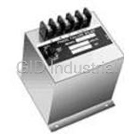
Electromechanical Relay 230VAC 10A SPST-NO Flange Protective Relay 1002X
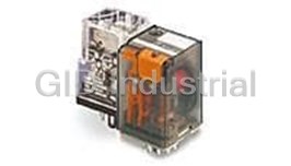
Electromechanical Relay 24VDC 475Ohm 20A 3PDT(35.5x35.6x57)mm Plug-In General Purpose Relay 1-139309...
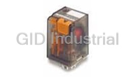
Electromechanical Relay 110VDC 10KOhm 20A 3PDT(35.5x35.6x57)mm Plug-In General Purpose Relay 1-13930...
Electromechanical Relay 220VDC 40KOhm 20A 3PDT(35.5x35.6x57)mm Plug-In General Purpose Relay 1-13930...
Electromechanical Relay 24VDC 475Ohm 20A 3PDT(35.5x35.6x57)mm Plug-In General Purpose Relay 1-139309...
Electromechanical Relay 24VDC 475Ohm 10A 3PDT(35.6x35.5x57)mm Plug-In Industrial Relay 1-1393092-8
Request a Quote

The quote request has been received
Close

Facing challenges or have inquiries? Feel free to contact us!
Call Us +1-469-283-2440
What they say about us
FANTASTIC RESOURCE
One of our top priorities is maintaining our business with precision, and we are constantly looking for affiliates that can help us achieve our goal. With the aid of GID Industrial, our obsolete product management has never been more efficient. They have been a great resource to our company, and have quickly become a go-to supplier on our list!
Bucher Emhart Glass
EXCELLENT SERVICE
With our strict fundamentals and high expectations, we were surprised when we came across GID Industrial and their competitive pricing. When we approached them with our issue, they were incredibly confident in being able to provide us with a seamless solution at the best price for us. GID Industrial quickly understood our needs and provided us with excellent service, as well as fully tested product to ensure what we received would be the right fit for our company.
Fuji
HARD TO FIND A BETTER PROVIDER
Our company provides services to aid in the manufacture of technological products, such as semiconductors and flat panel displays, and often searching for distributors of obsolete product we require can waste time and money. Finding GID Industrial proved to be a great asset to our company, with cost effective solutions and superior knowledge on all of their materials, it’d be hard to find a better provider of obsolete or hard to find products.
Applied Materials
CONSISTENTLY DELIVERS QUALITY SOLUTIONS
Over the years, the equipment used in our company becomes discontinued, but they’re still of great use to us and our customers. Once these products are no longer available through the manufacturer, finding a reliable, quick supplier is a necessity, and luckily for us, GID Industrial has provided the most trustworthy, quality solutions to our obsolete component needs.
Nidec Vamco
TERRIFIC RESOURCE
This company has been a terrific help to us (I work for Trican Well Service) in sourcing the Micron Ram Memory we needed for our Siemens computers. Great service! And great pricing! I know when the product is shipping and when it will arrive, all the way through the ordering process.
Trican Well Service
GO TO SOURCE
When I can't find an obsolete part, I first call GID and they'll come up with my parts every time. Great customer service and follow up as well. Scott emails me from time to time to touch base and see if we're having trouble finding something.....which is often with our 25 yr old equipment.
ConAgra Foods