

 Manufacturers
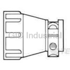
TE CONNECTIVITY 1-206138-0
Description
Cable Clamps and Clips Clamp Screw Thermoplastic Black Bulk
1-206138-0
Part Number
1-206138-0
Price
Request Quote
Manufacturer
TE CONNECTIVITY
Lead Time
Request Quote
Category
Wire and Cables » Cable Clamps and Clips
Specifications
Manufacturer
TE Connectivity
Manufacturers Part #
1-206138-0
Lead Time
1 Week Lead Time
Industry Aliases
1-206138-0
Sub-Category
Cable Clamps and Clips
Brand
AMP
Factory Pack Quantity
1
Datasheet
DDEController?Action=showdoc&DocId=Catalog+Section%7F82021_CPC_sections1-5%7F0807%7Fpdf%7FEnglish%7FENG_CS_82021_CPC_sections1-5_0807.pdf
3179 KiB

Extracted Text
RoHS Ready AMP Circular Connectors for Commercial Signal & Power Applications Tyco Electronics Corporation Harrisburg, PA tycoelectronics.com 82021-XXX-MS-FP-Rev. 6-07 OG3B Note: All part numbers AMP Circular Connectors for are RoHS Compliant. Commercial Signal and Power Applications Introduction Product Facts n Certified by MIL-C-5015 Style Circular Miniature CPC Canadian Standards R Plastic Connectors (CPC) Connectors n Lightweight, all-plastic and Association, metal-shell connectors Product Facts Product Facts File No. LR 7189 n CPC connectors are UL n Intermateable with Metal-Shell n Compact, high contact density, n Produced under a Quality 94V-0 rated and made of sizes 20-14 and environmentally sealed Management System certified stabilized, heat resistant, self- 18-10, MIL-C-5015 Style connectors to ISO 9001 extinguishing thermoplastic connectors n A copy of the n Uses existing Mini-Universal material certificate is available n High impact resistant MATE-N-LOK stamped and n Metal-shell CPC connector upon request. plastic housing made of formed pin and socket contacts housings made of UL 94V-0 rated UL 94V-0 rated material n Certain products meet n Two shell sizes—available thermoplastic VDE Standard 062 n Lightweight in 1 to 4 and 5 to 9 position n Operating temperature range: configurations n Lower cost than standard MIL-C- -40°C to +105°C Six connector series for 5015 connectors Need more information? different interconnection n Available in panel or chassis requirements: n Industry accepted Type III+ pin Call Technical Support. mount and free-hanging and socket contacts, available n Series 1—Standard density, configurations They are staffed with specialists on reels in strip form for high signal and low-current well versed in Tyco Electronics n Quick connect/disconnect volume, low cost, automatic applications using durable products. They can provide: capability with thread assist, machine terminations, or in Multimate contacts (.062 [1.57] positive detent coupling loose piece form for low n Technical Support pin diameter) volume, prototype or n Catalogs n Built-in pin and socket n Series 2—High density maintenance and repair n Technical Documents protection applications using Size n Product Samples n Improved alignment (U.S. n Polarized for proper mating of 20 DM and 20 DF contacts (.040 n Authorized Tyco Electronics Standard MIL-C-5015 connector halves [1.02] pin diameter) Distributor Locations Connectors) prevents mismating n Special connector configurations n Series 3—Low density, power with other housing insert offer special solder and posted applications with Type XII arrangements contacts, special receptacles contacts capable of carrying up to ©1973, 1975, 1976, 1978, 1981, 1983, 1985, n Recognized under the 1989, 1990, 1991, 1992, 1995, 1996, 1999, 2000, with or without threaded inserts 35 amperes of current Component Program of 2001, 2002, 2004, 2006 and 2007 by Tyco n Full complement of optional n Series 4—Combination of Electronics Corporation. All Rights Reserved. Underwriters accessories standard and power density R AMP, AMPOMATOR, AMP-O-LECTRIC, Laboratories Inc., AMP-O-MATIC, AMP-TAPETRONIC, application with Type III+ and File No. E28476 n Recognized under the CERTI-CRIMP, COAXICON, MATE-N-LOK, Type XII contacts POWERBAND, PRO-CRIMPER and TYCO are Component Program of n Certified by trademarks. Underwriters n Series 5—Power density Canadian Standards Komax and TopWin are trademarks of Laboratories Inc. R application with Size 8 screw Association, R Komax AG. for 250 VAC, rms machined and precision formed File No. LR 7189 TETRASEALS is a trademark of or 250 VDC, Service‡; contacts Parker Hannifin Corporation. Series 1 and Series 3 (600 V); AIRflex, FLEXAgraff, FLEXAquick, and ROHRflex n Series 6—Combination of Series 4 (600 V) and are trademarks of Flexa GmbH & Co. standard and power density Series 2, Series 6 (250 V) Other products, logos, and Company names application with Type III+ and mentioned herein may be trademarks of their File No. E28476 Size 8 contacts respective owners. ‡Select connectors are recognized for 600 volts service. certain electrical and electronic n Downloadable Technical Data Restriction on the use of Getting the Information products sold into the EU as of Hazardous Substances (RoHS) You Need n Customer Information 1 July 2006. Presentation At Tyco Electronics, we’re Our comprehensive on-line Note - For purposes of this ready to support your RoHS RoHS Customer Support Center n More detailed information Catalog, included within the requirements. We’ve assessed provides a forum to answer regarding the definitions used definition of RoHS Compliant more than 1.5 million end your questions and support above are products that are clearly items/components for RoHS your RoHS needs. A RoHS FAQ So whatever your questions “Out of Scope” of the RoHS compliance, and issued new (Frequently Asked Questions) is when it comes to RoHS, we’ve Directive such as hand tools part numbers where any available with links to more got the answers at and other non-electrical change was required to detailed information. You can www.tycoelectronics.com/leadfree accessories. Information eliminate the restricted also submit RoHS questions regarding RoHS compliance is materials. and receive a response within provided based on reasonable 24 hours during a normal work Part numbers in this catalog are inquiry of our suppliers and week. The Support Center also RoHS Compliant, unless represents our current actual provides: marked otherwise. These knowledge based on the products comply with European n Cross-Reference from Non- information provided by our Union Directive 2002/95/EC as compliant to Compliant suppliers. This information is amended 1 January 2006 that Products subject to change. For latest restricts the use of lead, n Ability to browse RoHS compliance status, refer to our mercury, cadmium, hexavalent Compliant Products in our website referenced at right. chromium, PBB, and PBDE in on-line catalog 2 Catalog 82021 Dimensions are in inches and Dimensions are shown for USA: 1-800-522-6752 South America: 55-11-2103-6000 Revised 7-07 millimeters unless otherwise reference purposes only. Canada: 1-905-470-4425 Hong Kong: 852-2735-1628 specified. Values in brackets Specifications subject Mexico: 52-55-1106-0800 Japan: 81-44-844-8013 www.tycoelectronics.com are metric equivalents. to change. C. America: 57-1-254-4444 UK: 44-208-420-8341 ISO 9001 Certified Note: All part numbers AMP Circular Connectors for are RoHS Compliant. Commercial Signal and Power Applications Table of Contents Introduction . . . . . . . . . . . . . . . . . . . . . . . . . . . . . . . . . . . . . . . . . . . . . . . . . . . . . . . . . . . . . . . . . . . . . . . . . . .2 Contents . . . . . . . . . . . . . . . . . . . . . . . . . . . . . . . . . . . . . . . . . . . . . . . . . . . . . . . . . . . . . . . . . . . . . . . . . . . . .3 Connector Series and Types . . . . . . . . . . . . . . . . . . . . . . . . . . . . . . . . . . . . . . . . . . . . . . . . . . . . . . . . . . . . .4, 5 Performance Characteristics . . . . . . . . . . . . . . . . . . . . . . . . . . . . . . . . . . . . . . . . . . . . . . . . . . . . . . . . . . . . . . .6 Internal Protection (IP) Codes . . . . . . . . . . . . . . . . . . . . . . . . . . . . . . . . . . . . . . . . . . . . . . . . . . . . . . . . . . . . . .7 Current Carrying Capabilities . . . . . . . . . . . . . . . . . . . . . . . . . . . . . . . . . . . . . . . . . . . . . . . . . . . . . . . . . . . . . .8 Example of New Current Rating Format . . . . . . . . . . . . . . . . . . . . . . . . . . . . . . . . . . . . . . . . . . . . . . . . . . . . . . .9 CPC, Series 1 Cable or Panel Mount Connectors . . . . . . . . . . . . . . . . . . . . . . . . . . . . . . . . . . . . . . . . . . . . . . . . . . . .10, 11 Printed Circuit Board Mount Connectors . . . . . . . . . . . . . . . . . . . . . . . . . . . . . . . . . . . . . . . . . . . . . . .12, 13 Square Flange Receptacles with Round Posted Contacts . . . . . . . . . . . . . . . . . . . . . . . . . . . . . . . . . . . . .13 Square Flange Receptacles with Solder Cup Contacts . . . . . . . . . . . . . . . . . . . . . . . . . . . . . . . . . . . . . . .14 Feed-Thru Connectors . . . . . . . . . . . . . . . . . . . . . . . . . . . . . . . . . . . . . . . . . . . . . . . . . . . . . . . . . . . . . . . .14 Square Flange Receptacles, Right-Angle, Posted . . . . . . . . . . . . . . . . . . . . . . . . . . . . . . . . . . . . . . . .15,16 Contacts, Type III+ (including Lead Free and Enhanced High Current) . . . . . . . . . . . . . . . . . . . . . . . .17-20 Contacts, Type II . . . . . . . . . . . . . . . . . . . . . . . . . . . . . . . . . . . . . . . . . . . . . . . . . . . . . . . . . . . . . . . . . . . . .21 Contacts, Subminiature Coaxial . . . . . . . . . . . . . . . . . . . . . . . . . . . . . . . . . . . . . . . . . . . . . . . . . . . . . .22, 23 Contact Arrangements, Series 1 . . . . . . . . . . . . . . . . . . . . . . . . . . . . . . . . . . . . . . . . . . . . . . . . . . . . . . . . .24 Component Dimensions, Series 1 . . . . . . . . . . . . . . . . . . . . . . . . . . . . . . . . . . . . . . . . . . . . . . . . . . . . . . . .25 CPC, Series 2 Cable or Panel Mount Connectors . . . . . . . . . . . . . . . . . . . . . . . . . . . . . . . . . . . . . . . . . . . . . . . . . . . . . . .26 Printed Circuit Board Mount Connectors . . . . . . . . . . . . . . . . . . . . . . . . . . . . . . . . . . . . . . . . . . . . . . . . . .27 Square Flange Feed-Thru Receptacles . . . . . . . . . . . . . . . . . . . . . . . . . . . . . . . . . . . . . . . . . . . . . . . . . . .28 Contacts, Size 20 DF Crimp . . . . . . . . . . . . . . . . . . . . . . . . . . . . . . . . . . . . . . . . . . . . . . . . . . . . . . . . . . . .29 Contacts, Size 20 DM Crimp and 20 DF Solder . . . . . . . . . . . . . . . . . . . . . . . . . . . . . . . . . . . . . . . . . . . . .30 Contact Arrangements, Series 2 . . . . . . . . . . . . . . . . . . . . . . . . . . . . . . . . . . . . . . . . . . . . . . . . . . . . . . . . .31 Component Dimensions, Series 2 . . . . . . . . . . . . . . . . . . . . . . . . . . . . . . . . . . . . . . . . . . . . . . . . . . . . . . . .32 CPC, Series 3 Plugs and Receptacles, Series 3 . . . . . . . . . . . . . . . . . . . . . . . . . . . . . . . . . . . . . . . . . . . . . . . . . . . . . . . .33 Power Contacts, Type XII . . . . . . . . . . . . . . . . . . . . . . . . . . . . . . . . . . . . . . . . . . . . . . . . . . . . . . . . . . .34, 35 Contact Arrangements, Series 3 . . . . . . . . . . . . . . . . . . . . . . . . . . . . . . . . . . . . . . . . . . . . . . . . . . . . . . . . .35 Component Dimensions, Series 3 . . . . . . . . . . . . . . . . . . . . . . . . . . . . . . . . . . . . . . . . . . . . . . . . . . . . . . . .36 CPC, Series 4 Plugs and Receptacles, Series 4 . . . . . . . . . . . . . . . . . . . . . . . . . . . . . . . . . . . . . . . . . . . . . . . . . . . . . . . .37 Contact Arrangements, Series 4 . . . . . . . . . . . . . . . . . . . . . . . . . . . . . . . . . . . . . . . . . . . . . . . . . . . . . . . . .38 CPC Connector Accessories Cable Clamps . . . . . . . . . . . . . . . . . . . . . . . . . . . . . . . . . . . . . . . . . . . . . . . . . . . . . . . . . . . . . . . . . . . .38, 39 Back-Shell Extender and Panel Mount Flanges . . . . . . . . . . . . . . . . . . . . . . . . . . . . . . . . . . . . . . . . . . . . .40 Flexible Cable Boots and Internal Cable Grips . . . . . . . . . . . . . . . . . . . . . . . . . . . . . . . . . . . . . . . . . . . . . .41 Keying Plugs . . . . . . . . . . . . . . . . . . . . . . . . . . . . . . . . . . . . . . . . . . . . . . . . . . . . . . . . . . . . . . . . . . . . . . . .42 Sealed CPC Connectors One-Piece Sealed CPC . . . . . . . . . . . . . . . . . . . . . . . . . . . . . . . . . . . . . . . . . . . . . . . . . . . . . . . . . . . . . 43-45 Two-Piece Sealed CPC . . . . . . . . . . . . . . . . . . . . . . . . . . . . . . . . . . . . . . . . . . . . . . . . . . . . . . . . . . . . . . . .46 .125 POWERBAND Contacts . . . . . . . . . . . . . . . . . . . . . . . . . . . . . . . . . . . . . . . . . . . . . . . . . . . . . . . . . .47 Connectors, Series 5 and Wire Entry Seals . . . . . . . . . . . . . . . . . . . . . . . . . . . . . . . . . . . . . . . . . . . . . . .48 Connectors, Series 6 and Wire Entry Seals . . . . . . . . . . . . . . . . . . . . . . . . . . . . . . . . . . . . . . . . . . . . . . .49 Connectors, Special Series 1 . . . . . . . . . . . . . . . . . . . . . . . . . . . . . . . . . . . . . . . . . . . . . . . . . . . . . . . . . .50 Wire Entry Seal Kits and Flange Seals . . . . . . . . . . . . . . . . . . . . . . . . . . . . . . . . . . . . . . . . . . . . . . . . . . .51 CPC Connector Sealing Accessories Sealing Caps and Cable Entry Seals . . . . . . . . . . . . . . . . . . . . . . . . . . . . . . . . . . . . . . . . . . . . . . . . . . . . .52 Jacketed Cable Seals and Rubber Boot . . . . . . . . . . . . . . . . . . . . . . . . . . . . . . . . . . . . . . . . . . . . . . . . . . .53 Flexible Cable Protection System . . . . . . . . . . . . . . . . . . . . . . . . . . . . . . . . . . . . . . . . . . . . . . . . . . . . . . . .54 MIL-C-5015 Style Circular Plastic Connectors Introduction . . . . . . . . . . . . . . . . . . . . . . . . . . . . . . . . . . . . . . . . . . . . . . . . . . . . . . . . . . . . . . . . . . . . . . . . .55 Connectors, Plugs and Receptacles—Shell Size 20-14 . . . . . . . . . . . . . . . . . . . . . . . . . . . . . . . . . . . . . . .56 Connectors, Plugs and Receptacles—Shell Size 18-10, and Type III+ Contacts . . . . . . . . . . . . . . . . . . .57 Metal-Shell Circular Plastic Connectors Introduction . . . . . . . . . . . . . . . . . . . . . . . . . . . . . . . . . . . . . . . . . . . . . . . . . . . . . . . . . . . . . . . . . . . . . . . . .58 Receptacles and Plugs, Series 1, Standard Sex . . . . . . . . . . . . . . . . . . . . . . . . . . . . . . . . . . . . . . . . . . . .59 Receptacles and Plugs, Series 1, Reverse Sex . . . . . . . . . . . . . . . . . . . . . . . . . . . . . . . . . . . . . . . . . . . . .60 Contact Arrangements, Series 1 . . . . . . . . . . . . . . . . . . . . . . . . . . . . . . . . . . . . . . . . . . . . . . . . . . . . . . . . .61 Receptacles and Plugs, Series 2, Standard Sex . . . . . . . . . . . . . . . . . . . . . . . . . . . . . . . . . . . . . . . . . . . .62 Receptacles and Plugs, Series 2, Reverse Sex . . . . . . . . . . . . . . . . . . . . . . . . . . . . . . . . . . . . . . . . . . . . .63 Contact Arrangements, Series 2 . . . . . . . . . . . . . . . . . . . . . . . . . . . . . . . . . . . . . . . . . . . . . . . . . . . . . . . . .64 Receptacles and Plugs, Series 3, Standard Sex . . . . . . . . . . . . . . . . . . . . . . . . . . . . . . . . . . . . . . . . . . . .65 Receptacles and Plugs, Series 3, Reverse Sex . . . . . . . . . . . . . . . . . . . . . . . . . . . . . . . . . . . . . . . . . . . . .66 Contact Arrangements, Series 3 . . . . . . . . . . . . . . . . . . . . . . . . . . . . . . . . . . . . . . . . . . . . . . . . . . . . . . . . .67 Receptacles and Plugs, Series 4, Standard Sex . . . . . . . . . . . . . . . . . . . . . . . . . . . . . . . . . . . . . . . . . . . .68 Contact Arrangements, Series 4 . . . . . . . . . . . . . . . . . . . . . . . . . . . . . . . . . . . . . . . . . . . . . . . . . . . . . . . . .69 Component Dimensions, Series 1, 2, 3 and 4 . . . . . . . . . . . . . . . . . . . . . . . . . . . . . . . . . . . . . . . . . . . . . . .70 Metal-Shell CPC Connector Accessories Cable Clamps, Cable Entry Seals and Protective Cap Assemblies . . . . . . . . . . . . . . . . . . . . . . . .38, 39, 71 Miniature CPC Connectors Introduction . . . . . . . . . . . . . . . . . . . . . . . . . . . . . . . . . . . . . . . . . . . . . . . . . . . . . . . . . . . . . . . . . . . . . . . . .72 Plugs, Receptacles and Contacts . . . . . . . . . . . . . . . . . . . . . . . . . . . . . . . . . . . . . . . . . . . . . . . . . . . . .73-75 Accessories . . . . . . . . . . . . . . . . . . . . . . . . . . . . . . . . . . . . . . . . . . . . . . . . . . . . . . . . . . . . . . . . . . . . . . . . .75 Application Tooling . . . . . . . . . . . . . . . . . . . . . . . . . . . . . . . . . . . . . . . . . . . . . . . . . . . . . . . . . . . . . . . . . .76-79 Technical Documents . . . . . . . . . . . . . . . . . . . . . . . . . . . . . . . . . . . . . . . . . . . . . . . . . . . . . . . . . . . . . . . . . . .80 Part Number Index Products . . . . . . . . . . . . . . . . . . . . . . . . . . . . . . . . . . . . . . . . . . . . . . . . . . . . . . . . . . . . . . . . . . . . . . . . . . . . .81, 82 Tooling . . . . . . . . . . . . . . . . . . . . . . . . . . . . . . . . . . . . . . . . . . . . . . . . . . . . . . . . . . . . . . . . . . . . . . . . . . . . . . . . . .83 Part Number Cross Reference (Non-Compliant to RoHS Compliant) . . . . . . . . . . . . . . . . . . . . . . . . . . . . . . . . . .83 Global Contacts . . . . . . . . . . . . . . . . . . . . . . . . . . . . . . . . . . . . . . . . . . . . . . . . . . . . . . . . . . . . . . . . . . . . . . . . . . . .84 3 Catalog 82021 Dimensions are in inches and Dimensions are shown for USA: 1-800-522-6752 South America: 55-11-2103-6000 Revised 7-07 millimeters unless otherwise reference purposes only. Canada: 1-905-470-4425 Hong Kong: 852-2735-1628 specified. Values in brackets Specifications subject Mexico: 52-55-1106-0800 Japan: 81-44-844-8013 www.tycoelectronics.com are metric equivalents. to change. C. America: 57-1-254-4444 UK: 44-208-420-8341 Note: All part numbers AMP Circular Connectors for are RoHS Compliant. Commercial Signal and Power Applications Connector Series and Types Series 1—Size 16 Contacts 1 3 Series 1 connectors permit subminiature coaxial Type III solder contacts the use of multiple combina- contacts, interchangeable in and posted contacts for pc 4 7 tions of signal and coaxial the same Multimate contact board applications are also circuits in the same housing cavity. Type III+ contacts available. Many connector 6 11 by accepting durable (.062 [1.57] pin diameter) arrangements offer both Multimate contacts. These are capable of carrying a standard and reverse sex pin and socket contacts maximum of 13 amperes contact loading—from 4 12 14 include Type III+ and when crimped in wire. thru 37 positions. Series 2—Size 20 Contacts 3 1 Series 2 connectors accept for wrap-type and pc board 4 8 Size 20 DF (precision applications. Maximum 9 14 formed) and Size 20 DM current carrying capability (screw-machined) pin and is 7.5 amperes. Many 20 15 socket contacts with a .040 connector arrangements [1.02] pin diameter, Size 20 offer both standard and 25 21 DF contacts are available in reverse sex contact crimp and solder versions, loading—from 8 thru 63 28 26 as well as a posted version positions. Series 3—Power Contacts 2 Series 3 connectors accept 10 AWG [1.4 to 5 mm ]. 12 Type XII power contacts Two connector sizes are which can carry up to 25 available in both standard 3 5 amps per contact. These and reverse sex connector contacts will accommodate arrangements 3 and 7 a wire size range of 16 to positions. 6 7 Series 4—Combination 1 Size 16 and Power Contacts 23 Series 4 connectors accept power circuit capabilities of 4 5 Size 16 Multimate and Series 3 connectors. 7 10 Type XII power contacts, Available in two connector 6 8 combining the signal and sizes offering power mixing coaxial circuit capabilities of combinations totaling 16 11 13 Series 1 connectors with the and 22 positions. 14 16 15 4 Catalog 82021 Dimensions are in inches and Dimensions are shown for USA: 1-800-522-6752 South America: 55-11-2103-6000 Revised 7-07 millimeters unless otherwise reference purposes only. Canada: 1-905-470-4425 Hong Kong: 852-2735-1628 specified. Values in brackets Specifications subject Mexico: 52-55-1106-0800 Japan: 81-44-844-8013 www.tycoelectronics.com are metric equivalents. to change. C. America: 57-1-254-4444 UK: 44-208-420-8341 Note: All part numbers AMP Circular Connectors for are RoHS Compliant. Commercial Signal and Power Applications Connector Series and Types (Continued) Series 5—Power Contacts 1 1 2 2 .125 POWERBAND Series 5 connectors combine performance of the best Mil Rated at 600 VAC or VDC, the revolutionary Spec Size 8 screw-machined 45 amperes maximum in performance of the new contacts with the economy a single contact, the AMP POWERBAND and productivity of strip-fed, connectors are available in Contact, high current precision formed contacts. free-hanging and panel- 3 3 contact in configurations mount applications—one Series 5 connectors are similar to the Series 3 connector configuration environmentally sealable to connectors. AMP containing three .125 meet IEC IP 65 and IP 67 POWERBAND contacts POWERBAND contacts. specifications. offer the electrical Series 6—Combination, 2 Size 16 and .125 3 1 POWERBAND Contacts This combination of power Series 6 combines the high and signal contacts is current and environmental offered in one connector sealing capability of configuration containing Series 5, POWERBAND two .125 POWERBAND 10 8 contacts, and the reliability contacts and eight 9 of signal carrying, low Type III+ signal pin and current Type III+ contacts. socket contacts. MIL-C-5015 Style—Size 16 Contacts This new addition to the AMP and lower cost than existing economies of crimp Circular Plastic Connector Line metal-shell connectors. In Type III+ pin and socket is specifically designed to be addition the connector design contacts in reel-mounted, intermateable with Metal- prevents mismating when strip-form for high volume Shell size 20-14 and 18-10, used with other insert automatic machine MIL-C-5015 Style connector arrangements. As part of termination, as well as in loose systems. The high impact the AMP Multimate family of piece-form for low volume, resistant plastic housing offers connectors, the MIL-C-5015 prototype or maintenance and the advantages of light weight style connector offers the repair. Metal-Shell, Circular Plastic Connectors Metal-Shell CPC connectors shell sizes 14, 22 and 28, consist of a black and in two basic thermoplastic insert in a configurations consisting nickel-plated, zinc alloy of plugs and square shell. These connectors flange receptacles. are currently available in Miniature CPC Connectors Two shell sizes (8 or 11) are Featuring high contact These compact connectors available, accommodating density and IP67 sealing, accept existing Mini- from 1 to 4 and 5 to 9 these durable connectors Universal MATE-N-LOK pin positions. are well suited for many and socket contacts, 2 wire-to-wire, wire-to-board, 30-18 AWG [.05-.8 mm ]. and wire-to-panel applications. 5 Catalog 82021 Dimensions are in inches and Dimensions are shown for USA: 1-800-522-6752 South America: 55-11-2103-6000 Revised 7-07 millimeters unless otherwise reference purposes only. Canada: 1-905-470-4425 Hong Kong: 852-2735-1628 specified. Values in brackets Specifications subject Mexico: 52-55-1106-0800 Japan: 81-44-844-8013 www.tycoelectronics.com are metric equivalents. to change. C. America: 57-1-254-4444 UK: 44-208-420-8341 Note: All part numbers AMP Circular Connectors for are RoHS Compliant. Commercial Signal and Power Applications Performance Characteristics — CPC and Metal-Shell CPC Connectors More information on the Test Description Procedure Requirements performance of AMP CPC Maintenance Contacts removed and No damage to contacts and metal-shell CPC Aging reinserted 10 times using or housings. Contact connectors is available by applicable tools retention maintained requesting the following AMP Product Specifications: Contact Retention Axial load applied to Contacts remain in contact to displace to the place when subjected to 108-10024–– rear of the connector a minimum 10 lb. load* CPC Connectors 108-10037–– Dielectric Withstanding Connectors subjected to No breakdown or Type XII Contacts Voltage (MIL-STD-1344, 1500 volts rms at sea flashover 108-10020–– Method 3001) level Size 20 DM and 20 DF Thermal Shock Connectors subjected to No damage Contacts five cycles of temperature 108-10040–– change (-55°C and +125°C) Metal-Shell CPC Connectors Vibration Connectors vibrated No damage or loosening of 108-10042–– (MIL-STD-202, (wired and mated). parts. No interruption Type III+ Contacts Method 204, Contacts wired in series of electrical continuity 108-1579–– Test Condition B) with 100 milliamperes longer than 10 microseconds Sealed CPC Connectors flowing during the test with Removeable Contacts Physical Shock Connectors shocked No damage or loosening (MIL-STD-202, 50 G (wired and mated). of parts. No interruption of Method 213A, Contacts wired in series electrical continuity longer Test Condition A) with 100 milliamperes than 10 microseconds flowing during the test Durability Connectors mated and No wear through unmated 25 times with tin damage to plating plated contacts and 500 times with gold plated contacts Corrosion (Salt Spray) Mated connectors No damage (MIL-STD-202, Method 101, subjected to 5% salt Test Condition B) spray for 48 hours Protection Against a. Test wire is pushed a. Must not touch live parts Solids into mated connectors b. No dust deposits b. Mated connectors observed on mating subjected to circulating surfaces talcum powder Protection Against Water is projected through No water deposits shall Water jets against mated be observed on mating connector from any direction surfaces of contacts and then temporarily or housings immersed in water Temperature Life Mated connectors No damage subjected to a temperature of +125°C for 200 hours Insulation Resistance Measurement made 5000 megohms (MIL-STD-1344, between adjacent contacts minimum ambient Method 3003) with connector mated temperature Humidity Mated connectors Minimum insulation (MIL-STD-202, Method 103, subjected to 10 days resistance of Test Condition B) moisture test 100 megohms *For size 16 contacts. Size 8 contacts 25 lb. load, min. 6 Catalog 82021 Dimensions are in inches and Dimensions are shown for USA: 1-800-522-6752 South America: 55-11-2103-6000 Revised 7-07 millimeters unless otherwise reference purposes only. Canada: 1-905-470-4425 Hong Kong: 852-2735-1628 specified. Values in brackets Specifications subject Mexico: 52-55-1106-0800 Japan: 81-44-844-8013 www.tycoelectronics.com are metric equivalents. to change. C. America: 57-1-254-4444 UK: 44-208-420-8341 Note: All part numbers AMP Circular Connectors for are RoHS Compliant. Commercial Signal and Power Applications Levels of Protection for Electric Operating Material According to IEC 60529 and IEC 60947, Appendix C Internal Protection (IP) Environmentally Protected Definition: Circular Plastic Connectors, for Mated CPC Connectors n Per IEC 60947, Appendix C— Pertains to low voltage switchgear and Utilizing Peripheral Seals control gear. and either Wire Entry Seals n Per IEC 60529—Pertains to degrees (for Discrete Wire of protection provided by enclosures Applications) or Heat (IP code). Shrink Boots (for Jacketed Cable Applications). Sample Designation: Available are Various (Where x is a numeral value), i.e. IP 65 Sizes, Series 1, 5 and 6. IP Codes IP X X 1 2 Index Letter Degree of Protection Degree of Protection against ingress of solid against ingress of water foreign objects Degree of Protection against ingress of Degree of Protection against Protection, X solid foreign objects Protection, X ingress of water 1 2 0 No Protection No Protection Protection against objects Vertical Dripping— >50mm diameter— 1 1 Protection against vertical including inadvertently drops of water touched by hands Dripping <15°— Protection against objects Protection against dripping 2 2 >12.5mm—including fingers water when the enclosure is tilted 15° from vertical Protection against objects Spraying at an angle up 3 3 >2.5mm diameter including tools to 60° from vertical Protection against objects Splashing—Protection 4 >1.0mm diameter— 4 against water splashed including grains from any direction Jetting—Protection against Protection against ingress 5 5 water stream out of a nozzle, of solid foreign bodies from any direction Powerful Jetting—Protection against temporary flooding due Protection against ingress of dust 6 6 to powerful jet streams out of a nozzle from any direction Temporary immersion—Protection 7 against temporary immersion 7 Catalog 82021 Dimensions are in inches and Dimensions are shown for USA: 1-800-522-6752 South America: 55-11-2103-6000 Revised 7-07 millimeters unless otherwise reference purposes only. Canada: 1-905-470-4425 Hong Kong: 852-2735-1628 specified. Values in brackets Specifications subject Mexico: 52-55-1106-0800 Japan: 81-44-844-8013 www.tycoelectronics.com are metric equivalents. to change. C. America: 57-1-254-4444 UK: 44-208-420-8341 Note: All part numbers AMP Circular Connectors for are RoHS Compliant. Commercial Signal and Power Applications Current Carrying Capabilities The total current capacity of CONTACT CURRENT GUIDE Maximum Current (Amperes) for Largest Wire Size each contact in a given 75 Type XII Upgrade connector is dependent upon the heat rise resulting from the Size 8 Upgrade combination of electrical loads 60 60 of the contacts in the connector 56 .125 POWERBAND Contact arrangement and the maximum 50 ambient temperature in which 45 Size 8 the connector will be operating. 45 Caution must be taken so that 35 Type XII this combination of conditions does not cause the internal Type I, Type II/III+ 30 temperature of the connector to Upgrade 23 exceed the maximum operating + Type III , Type II, temperature of the housing + Type III Posted 13 15 material. Several variables 11.85 Size 20 Upgrade which must be considered 7.5 when determining this 20 DF maximum current capability for 0 your application are: n Wire Size—Larger wire will n Connector Size—In general, n Current Load Distribution— n Ambient Temperature—With carry more current since it with more circuits in a Spreading those lines with higher ambient temperatures, has less internal resistance connector, less current per greater current loads through- less current can be carried. to current flow and generates contact can be carried. out the connector, particularly less heat. The wire also around the outer perimeter, conducts heat away from the will enhance heat dissipation. connector. design-life (EODL) conditions. loading density. A connector Current Rating Verification Temperature Practical current-carrying capac- containing 50% current-carrying Can a contact rated at 10 amps One other factor influencing ity is not an absolute, but an contacts will permit higher carry 10 amps? current levels is the maximum application-dependent condition. currents (per contact) than a operating temperature, for Maybe yes, but probably not. connector will at 75% loading. example, 105°C. If the appli- New Method Simplifies Ratings The reason lies in the test The loading percentage assumes cation has a high ambient conditions used to rate the To help the designer set the an even distribution of contacts temperature (over 75°C) the contact. If these conditions do appropriate current level, Tyco within the housing. If all 10 contact’s T-rise is limited by not adequately reflect the appli- Electronics has developed a contacts are grouped together in the maximum operating cation conditions, the actual method of specifying current- one section of a 20-position temperature. For example, an allowable current levels may be carrying capacity. This method connector, the loading density application temperature of lower than specified levels. For takes into account the various may approach 100%. 90°C limits the contact T-rise example, many manufacturers, application factors that influ- to 15°C. Since current The Importance of EODL including Tyco Electronics, test ence current rating. 2 produces heat (the I R law), the a single contact in air. This As stated, T-rise in a contact The method can be summarized current must be lowered to gives an accurate measure of depends on both resistance and as follows: limit the T-rise. the basic current-carrying current. As it ages, a contact’s capacity of the contact. Use the n The contact is aged to EODL A contact’s T-rise depends not resistance will increase. The 2 contact alone in air and it can conditions by durability only on its I R Joule heating, but contact designer will specify a certainly carry 10 ampere. Use cycling, thermal cycling, and also on its ability to dissipate maximum resistance for the it in a multi-position connector environmental exposure. the heat. Consider a contact in contact, this level is the end-of- surrounded by other current- a multi-contact housing. Joule design-life resistance. Before n The contact’s resistance carrying contacts or in high heating in multiple contacts will the contact is tested for current, stability is verified. ambient temperatures, and the raise the local ambient temper- Tyco Electronics subjects it to a n The current necessary to contact should carry less ature. Since the contact will not sequence of tests that exercises produce the specified tempera- current. be able to dissipate its own the major failure mechanisms ture rise is measured. This heat as well by convection, the and thereby simulates EODL Similarly, as the contact ages T-rise is usually 30°C. maximum T-rise will be realized conditions. Conditioning and stress relaxation, environ- n A rating factor is determined at a lower current level. Conse- includes mating cycling, indus- mental cycling, and other to allow derating of multiple quently, the allowable current trial mixed-flowing gases, degradation factors take their contacts in the same housing level must be lower to maintain humidity and temperature toll, the contact’s current- and for different conductor an acceptable T-rise. cycling, and vibration to carrying capacity decreases. sizes. sequentially introduce wear, A prudent design must set For a given connector, the corrosion, stress relaxation, current levels for such end-of- current level will be set by the and mechanical disturbance. 8 Catalog 82021 Dimensions are in inches and Dimensions are shown for USA: 1-800-522-6752 South America: 55-11-2103-6000 Revised 7-07 millimeters unless otherwise reference purposes only. Canada: 1-905-470-4425 Hong Kong: 852-2735-1628 specified. Values in brackets Specifications subject Mexico: 52-55-1106-0800 Japan: 81-44-844-8013 www.tycoelectronics.com are metric equivalents. to change. C. America: 57-1-254-4444 UK: 44-208-420-8341 Note: All part numbers AMP Circular Connectors for are RoHS Compliant. Commercial Signal and Power Applications Presentation — An Example* Current Rating of connectors and their accept- The presentation of current- Figure 1 able contacts. Once you have carrying capacity in AMP 15 selected the wire size, current- product specifications includes Single Contact carrying capacity need, two parts: 18 AWG number of positions required, n First, a base curve showing and the type of contacts current levels versus T-rise for needed in your choice of 10 a single circuit and the largest connector, refer to this matrix wire size (See figure 1). This for a quick look at exactly what represents the maximum is acceptable in a given current capacity of the connector type. contact. The curve is usually 5 flat up to 75°C ambient and then drops off. Up to 75°C, the *Note: Data is not typical of a 30°C T-rise limits the amount specific CPC connector configu- of current, and above 75°C ration. For specific current 0 the current must be reduced 0 10 20 30 40 50 60 70 80 90 100 rating information based on % to keep the combination of Ambient Temperature (°C) connector loading, contact ambient temperature and Tyco Electronics. Graph shows the relationship between base current, ambient T-rise from exceeding the temperature, and contact T-rise. To demonstrate the method of maximum operating tempera- specifying current, consider the ture of 105°C. following application conditions; n Next are rating factors, a an ambient temperature of 65°C, table of multipliers to account a 50% loading of contacts in AWG for connector loading and for the housing, and 20 AWG smaller wire sizes (See figure 2). 2 [0.6mm ] wire. 18 20 22 24 26 The designer first determines n From Figure 1, the base the base current for the current rating is 14 ampere ambient conditions of the 2 with 18 AWG [0.8mm ] wire. application; then multiplies Single 1 .83 .69 .59 .50 this base current by the rating n Figure 2, the rating factor for factors to find the current 50% loading and 20 AWG level for the application’s 2 [0.6mm ] wire is 0.68. 30% .97 .80 .66 .57 .49 loading factor and wire size. n The specific rating for this application is the product of Practical Values the base rating and the rating 50% .83 .68 .57 .48 .42 factor: The current-rating method 14 x 0.68 = 9.5 ampere gives designers practical values applicable to their appli- n Each of the contacts can 70% .65 .53 .45 .38 .33 cations. While the specified carry 9.5 ampere. current levels for a contact may n However, if the ambient temper- be lower than for other testing ature is 80°C the allowable 100% .55 .45 methods, they are more practi- .38 .32 .28 T-rise becomes 25°C. The base cal and simplify the system current must be lowered to design process. 12.8 ampere so that the 105°C “Spec-manship” is replaced maximum operating tempera- by a realistic assessment of the ture is not exceeded. The Figure 2 current-carrying capacity of a current rating then becomes: Rating factors allow the base current to be adjusted for various contact under varying condi- connector loading and wire sizes. 12.8 x 0.68 = 8.7 ampere. tions of temperature, connector loading, and wire size. Specific current-carrying data based on EOL and % loading is Contact Selector Chart available from Tyco Electronics. Please contact your local Connector Posted Sub-Mini POWERBAND 20 DF Type I Type II Type III+ Type XII Type Type III+ Coax Contacts Tyco Electronics Sales Engineer or call Tyco Electronics. CPC Series 1 4 4 4 4 CPC Series 2 4 CPC Series 3 4 CPC Series 4 44 4 4 Connector/Contact Acceptability CPC Series 5 4 As previously stated, choosing CPC Series 6 44 4 4 the correct connector/contact CPC 5015 4 combination is fundamental CMC Series 1 44 4 4 to the successful function of CMC Series 2 4 all connectors. The Selector CMC Series 3 4 Chart shown at right, is designed to simplify your choice CMC Series 4 44 4 4 9 Catalog 82021 Dimensions are in inches and Dimensions are shown for USA: 1-800-522-6752 South America: 55-11-2103-6000 Revised 7-07 millimeters unless otherwise reference purposes only. Canada: 1-905-470-4425 Hong Kong: 852-2735-1628 specified. Values in brackets Specifications subject Mexico: 52-55-1106-0800 Japan: 81-44-844-8013 www.tycoelectronics.com are metric equivalents. to change. C. America: 57-1-254-4444 UK: 44-208-420-8341 % Loading Current Rating (Amperes) Note: All part numbers AMP Circular Connectors for are RoHS Compliant. Commercial Signal and Power Applications Circular Plastic Connectors, Size 1 ±.025 Square Flange Receptacle *G [±0.64] CPC Connectors, Series 1 ±.010 *J Dia. *Panel Thk. *F for Cable or Panel Mount [±0.25] .125 Max. (Accepts Type III+, High- [3.18] Current Power, Type II and Subminiature Coax Contacts) ±.010 ±.010 *E *F *D [±0.25] [±0.25] Max. +.007 *H Dia. –.000 [+0.18] *Thread Size *A (See chart) Max. Panel Cutout ±.015 *B [±0.38] ±.010 *C [±0.25] Free-Hanging Receptacle *A Max. Listed part numbers are for ±.015 *B [±0.38] connectors only; contacts ±.010 must be ordered separately. *C [±0.25] Material ±.010 *E Max. *D *L Max. [±0.25] Housing—Thermoplastic, 94V-0 rated, black *Note: See page 25 for callout dimensions *Thread Size *K Related Product Data (See chart) Max. Contacts—Pages 17-23 Plug *M Max. Contact Arrangement—Page 24 Component Dimensions—Page 25* Accessories—Pages 38-42, 52-54 Performance Characteristics— *N Max. Page 6 Application Tooling—Pages 76-79 Technical Documents—Page 80 *Thread Size (See chart) Standard Sex Connectors (Receptacles accept pin contacts, Plugs accept socket contacts) Square Flange Receptacle Replacement Coupling Rings Arrangement Keying Free-Hanging Plug With Threaded With Mounting Shell No. of Receptacle Shell Size Part No. 1 Inserts Holes Size Positions 11 213811-1 11-4 A 208130-1 206061-1 206153-1 206060-1 13 213813-1 13-9 A 208131-1 206705-1 206705-2 206708-1 17 213810-1 A 206036-8 206036-1 206036-3 206037-1 23 213812-1 17-16 B — 213862-1 — 213849-1 A 211839-1 206838-1 206838-2 206837-1 23-24 B — 213866-1 — 213851-1 A 787610-1 206151-1 206151-2 206150-1 Keying 23-37 B — 213860-1 — 213848-1 Molded-in keying in two configurations: 1 Four 4-40 threaded inserts per receptacle. A—Standard Configuration: 5 Keys Reverse Sex Connectors (Receptacles accept socket contacts, Plugs accept pin contacts) Square Flange Receptacle Arrangement Keying Free-Hanging Plug With Threaded With Mounting Shell No. of Receptacle 1 Inserts Holes Size Positions B—Optional Configuration: 4 Keys to prevent mismating of standard and 11-4 A 211102-1 206430-1 206430-2 206429-1 reverse sex. A 211103-1 206043-1 206043-3 206044-1 17-14 B — 796437-2 — 796449-1 A 206306-5 206306-1 206306-2 206305-1 23-37 B — 213864-1 — 213850-1 1 Four 4-40 threaded inserts per receptacle. Key Style “A” is the Standard 5 Locating Key arrangement. Key Style “B” is the 4 Locating Key arrangement. 10 Catalog 82021 Dimensions are in inches and Dimensions are shown for USA: 1-800-522-6752 South America: 55-11-2103-6000 Revised 7-07 millimeters unless otherwise reference purposes only. Canada: 1-905-470-4425 Hong Kong: 852-2735-1628 specified. Values in brackets Specifications subject Mexico: 52-55-1106-0800 Japan: 81-44-844-8013 www.tycoelectronics.com are metric equivalents. to change. C. America: 57-1-254-4444 UK: 44-208-420-8341 CPC Series 1 CPC Series 1 Note: All part numbers AMP Circular Connectors for are RoHS Compliant. Commercial Signal and Power Applications Circular Plastic Connectors, Series 1, VDE Tested Square Flange Receptacle ±.025 CPC Connectors, Series 1, *G [±0.64] ±.010 for Cable or Panel Mount *J Dia. *F *Panel Thk. [±0.25] .125 (Accepts Type III+, High- Max. [3.18] Current Power, Type II and Subminiature Coax Contacts) ±.010 ±.010 *F [±0.25] *D *E Max. [±0.25] +.007 *H Dia. –.000 [+0.18] *A *Thread Size Max. (See chart) Panel Cutout ±.015 *B [±0.38] ±.010 *C [±0.25] Free-Hanging Receptacle n Designed to meet *A requirements of VDE as Max. ±.015 shown in DIN *B [±0.38] Specification 57627 ±.010 *C [±0.25] n Recognized under the Component Program of Underwriters ±.010 *E Max. *D *L Max. [±0.25] Laboratories Inc. for 600 VAC and *Note: 600 VDC service, See page 25 for callout dimensions R *Thread Size *K File No. E28476 (See chart) Max. n Certified by Canadian Standards R Plug Association, *M Max. File No. LR 7189 Listed part numbers are for connectors only; contacts must be ordered separately. *N Max. Material *Thread Size Housing—Thermoplastic, 94V-0 rated, (See chart) black Standard Sex Connectors (Receptacles accept pin contacts, Plugs accept socket contacts) Square Flange Receptacle Arrangement Related Product Data Shell No. of Keying With Threaded With Mounting Plug 1 Size Positions Inserts Holes Contacts—Pages 17-23 13-7 A 211401-4 211401-1 211399-1 Contact Arrangement—Page 24 17-9 A 211767-2 211767-1 211766-1 Component Dimensions—Page 25* A 211771-2 211771-1 211770-2 23-19 Accessories—Pages 38-42, 52-54 B — 213870-1 213853-1 Performance Characteristics— 1 Four 4-40 threaded inserts per receptacle. Page 6 Reverse Sex Connectors (Receptacles accept socket contacts, Plugs accept pin contacts) Application Tooling—Pages 76-79 Technical Documents—Page 80 Arrangement Square Flange Receptacle Free-Hanging Shell No. of Keying With Threaded With Mounting Plug Receptacle 1 Size Positions Inserts Holes Replacement Coupling Rings 13-7 A 211398-4 211398-1 211398-2 211400-1 A — 211769-1 211769-3 211768-1 Shell Size Part No. 17-9 B — 796439-2 — 796450-1 13 213813-1 17 213810-1 A — 211773-1 — 211772-1 23-19 23 213812-1 B — 213868-1 — 213852-1 1 Four 4-40 threaded inserts per receptacle. Key Style “A” is the Standard 5 Locating Key arrangement. Key Style “B” is the 4 Locating Key arrangement. Keying A—Standard Configuration: 5 Keys B—Optional Configuration: 4 Keys 11 Catalog 82021 Dimensions are in inches and Dimensions are shown for USA: 1-800-522-6752 South America: 55-11-2103-6000 Revised 7-07 millimeters unless otherwise reference purposes only. Canada: 1-905-470-4425 Hong Kong: 852-2735-1628 specified. Values in brackets Specifications subject Mexico: 52-55-1106-0800 Japan: 81-44-844-8013 www.tycoelectronics.com are metric equivalents. to change. C. America: 57-1-254-4444 UK: 44-208-420-8341 Note: All part numbers AMP Circular Connectors for are RoHS Compliant. Commercial Signal and Power Applications Circular Plastic Connectors, Series 1 ±.015 1.435 Square Flange ±0.38 [36.45 ] .094 Receptacles, Printed [2.39] ±.010 Circuit Board Mount 1.125 ±.015 .420 ±0.25 [28.58 ] ±0.38 [10.67 ] with .025 [0.64] sq. solder tails Typ. B .150 Dia. [3.81] 4 Holes ±.010 1.050 ±.010 1.125 ±0.25 ±.015 [26.67 ] 1.435 ±0.25 [28.58 ] ±0.38 Dia. [36.45 ] Typ. A .125 Max. [3.18] Panel Thk. Standard Sex (Posted Pin Contacts) Material and Finish Receptacle Assemblies Contact Housing—Thermoplastic, 94V-0 rated, Dimensions Arrangement Keying Peripheral Finish Mounting 4-40 Threaded black No. Style Seal A B Code Holes Inserts Contacts— .119 .816 11-4 — 207825-9 A N A A—Duplex plated gold flash on entire 3.02 20.73 contact with .000030 [0.00076] min. .220 .816 13-7 — 1-796433-1 A N A gold on contact engagement area, tin on 5.59 20.73 the termination area .220 .816 208223-9 — AN A C—Plated tin on the entire contact, tin 5.59 20.73 13-9 on the termination area .220 .816 — 1-208223-0 AN A 5.59 20.73 — 1-207303-4 .220 .816 A A N Related Product Data 1-207303-5 — 5.59 20.73 C 17-16 1-207303-3 —A .220 .816 Contact Arrangement—Page 24 AN 5.59 20.73 213855-4 213855-3 B Performance Characteristics— .429 .679 Page 6 213782-4 — AN A 10.90 17.24 23-19 Technical Documents—Page 80 .618 .674 213859-2 — A N B 15.70 17.12 .220 .654 — 213588-2 CN A 5.59 16.61 .618 .679 213798-3 — A N A 15.70 17.24 Keying 23-24 .220 .654 213780-2 — AN A Molded-in keying in two configurations: 5.59 16.61 .429 .679 A—Standard Configuration: 5 Keys 213857-2 — AN B 10.90 17.24 .220 .654 1-206934-1 — AN A 5.59 16.61 206934-5 — N .119 .654 A A 3.02 16.61 — 1-206934-7 Y B—Optional Configuration: 4 Keys to 208132-2 — A C 23-37 prevent mismating of standard and .429 .654 1-206934-8 — A A N 10.90 16.61 reverse sex. 213854-3 — B A .618 .654 1-206934-9 — A N A 15.70 16.61 Note: Posts are .017 [0.43] offset from centerline of contacts. All posts must be oriented in the same plane for proper contact/post location. Other Available Posted Contacts Tyco Electronics can make available contacts with .119 various solder tail lengths Min. [3.02] for loading into the standard .618 Max. or reverse sex, square [15.70] flange receptacles for applications requiring custom solder tail lengths. 12 Catalog 82021 Dimensions are in inches and Dimensions are shown for USA: 1-800-522-6752 South America: 55-11-2103-6000 Revised 7-07 millimeters unless otherwise reference purposes only. Canada: 1-905-470-4425 Hong Kong: 852-2735-1628 specified. Values in brackets Specifications subject Mexico: 52-55-1106-0800 Japan: 81-44-844-8013 www.tycoelectronics.com are metric equivalents. to change. C. America: 57-1-254-4444 UK: 44-208-420-8341 CPC Series 1 CPC Series 1 Note: All part numbers AMP Circular Connectors for are RoHS Compliant. Commercial Signal and Power Applications Circular Plastic Connectors, Series 1 (Continued) Square Flange 1.050 1.435±.015 [26.67] Receptacles, Printed [36.45±0.38] Circuit Board Mount .420±.005 .094±.005 1.125±.005 [10.67±0.13] [2.39±0.13] [28.58±0.13] with .025 [0.64] sq. solder tails 1.125±.005 [28.58±0.13] 1.050±.005 1.110 Dia. Max. Dia. 1.435±.015 [26.67±0.13] [28.19] [36.45±0.38] ±.030 B A Typ. [±0.76] Material and Finish .125 [3.18] Housing—Thermoplastic, 94V-0 rated, Max. black Thk. Panel Contacts— A—Duplex plated gold flash on entire Reverse Sex (Posted Socket Contacts) contact with .000030 [0.00076] min. Receptacle Assemblies Contact Dimensions gold on contact engagement area, tin on Arrangement Keying Peripheral Finish Mounting 4-40 Threaded No. Style Seal the termination area AB Code Holes Inserts C—Plated tin on the entire contact, tin .159 .536 A N 208283-4 — A on the termination area 4.04 13.61 11-4 .704 .541 Related Product Data CN 1-788130-1 — A 17.88 13.74 Contact Arrangement—Page 24 .220 .536 17-9 1-213826-1 — CY A 5.59 13.61 Performance Characteristics— .368 .536 Page 6 AN 213729-9 213729-6 A 9.35 13.61 Technical Documents—Page 80 .220 .536 C Y 17-14 1-213825-7 — A Keying—Page 12 5.59 13.61 .159 .536 — 213729-8 CN A 4.04 13.61 Special CPC Connectors, .645 .394 AN 213858-3 — B 16.38 10.00 Square Flange Receptacles, .557 .374 Printed Circuit Board Mount CN 23-19 213781-9 — A 14.15 9.50 With Round Posted Contacts .368 .374 CY 213827-8 — A 9.35 9.50 (Size 16), Contact 2-208224-1 — A .557 .374 Arrangement 17-16 AN 14.15 9.50 213856-4 —B .368 .374 C N 1-208224-2 — A 9.35 9.50 23-37 .368 .374 CY 1-213828-6 — A 9.35 9.50 .159 .374 AN 207890-2 — A 4.04 9.50 Note: Posts are .017 [0.43] offset from centerline of contacts. All posts must be oriented in the same plane for proper Material and Finish contact/post location. Housing—Thermoplastic, 94V-0 rated, heat-stabilized, fire-resistant, self- extinguishing, black Contacts—Brass Plating— Connector Part No. 207292-1— Plated tin over .000050 [0.00127] min. nickel on entire contact Connector Part No. 207292-2— Plated .000030 [0.00076] min. gold over .000050 [0.00127] min. nickel on entire contact Notes: 1. Connector can be used for pressure bulkhead feed- thru (sealed) applications. Notes: 2. Receptacle is Standard Sex, supplied preloaded with 16 special round posted pin contacts, .030 [0.76] diameter. 13 Catalog 82021 Dimensions are in inches and Dimensions are shown for USA: 1-800-522-6752 South America: 55-11-2103-6000 Revised 7-07 millimeters unless otherwise reference purposes only. Canada: 1-905-470-4425 Hong Kong: 852-2735-1628 specified. Values in brackets Specifications subject Mexico: 52-55-1106-0800 Japan: 81-44-844-8013 www.tycoelectronics.com are metric equivalents. to change. C. America: 57-1-254-4444 UK: 44-208-420-8341 Note: All part numbers AMP Circular Connectors for are RoHS Compliant. Commercial Signal and Power Applications Circular Plastic Connectors, Series 1 (Continued) Special CPC Connectors, Square Flange Receptacles, ±.015 .420 With Solder Type Contacts ±0.38 [10.67 ] (Size 16), Contact .010 ± .094 0.25 [2.39± ] Arrangement 17-16 ±.010 .010 ± 1.050 1.090 Dia. Dia. ±0.25 0.25 [27.69± ] [26.67 ] Panel Thk. Solder Cup .125 Max. Contact [3.18] .015 ± .250 0.38 [6.35± ] .156 Material and Finish [3.96] Housing—Thermoplastic, 94V-0 rated, heat-stabilized, fire-resistant, self- extinguishing, black Contacts—Brass Notes: 1. Connector can be used for Plating— pressure bulkhead feed- Connector Part No. 206404-1— thru (sealed) applications. Plated .000030 [0.00076] min. gold over Notes: 2. Receptacle is standard .000030 [0.00076] min. nickel on entire sex, supplied preloaded contact with 16 special solder cup pin contacts. Connector Part No. 206404-2— Plated tin over .000100 [0.00254] min. copper on entire contact Receptacle, Feed-Thru .025 E [0.64] Panel Thk. .125 Max. .010 [3.18] Special CPC Connectors, D [0.25] Feed-Thru G Dia. Pressure Rating up to 30 psi .010 B [0.25] F Dia. (4 Holes) Pin Both Sides Panel Cutout .010 H Max. C [0.25] A Max. Plug Material and Finish Housing—Thermoplastic, 94V-0 rated, black J Max. Contacts—Copper alloy, gold over nickel plated Thread Size Part Numbers (See Chart) Standard Reverse Feed-Thru Arrangement Numbering Numbering Receptacle Plug Plug 11-4 206060-1 206516-1 206518-2 17-16 206037-1 206554-1 206552-1 Dimensions Dimensions Thread Arrangement Size A B C D E F G HJ Note: Feed-Thru Receptacles are fully loaded with Size 16, 1.209 .687 .094 .844 1.125 .125 .840 1.080 .975 5/8-24 11-4 30.71 17.45 2.39 21.44 28.58 3.18 21.34 27.43 24.77 UNEF-2A feed-thru pin contacts. Order Size 16 crimp, snap-in socket 1.209 1.050 .094 1.125 1.435 .150 1.210 1.080 1.349 15/16-20 17-16 30.71 26.67 2.39 28.58 36.45 3.81 30.73 27.43 34.26 UNEF-2A contacts for plugs separately. 14 Catalog 82021 Dimensions are in inches and Dimensions are shown for USA: 1-800-522-6752 South America: 55-11-2103-6000 Revised 7-07 millimeters unless otherwise reference purposes only. Canada: 1-905-470-4425 Hong Kong: 852-2735-1628 specified. Values in brackets Specifications subject Mexico: 52-55-1106-0800 Japan: 81-44-844-8013 www.tycoelectronics.com are metric equivalents. to change. C. America: 57-1-254-4444 UK: 44-208-420-8341 CPC Series 1 CPC Series 1 Note: All part numbers AMP Circular Connectors for are RoHS Compliant. Commercial Signal and Power Applications Circular Plastic Connectors, Series 1 (Continued) Square Flange Receptacles, Right-Angle, Posted with .025 [0.64] sq. solder tails *A Max. *B *C *D Max. *E Max. .150 [3.81] Material and Finish Housing—Thermoplastic, 94V-0 rated, Location Wafer 4 Holes .125 black *F Max. [3.18] .025 Sq. Location Wafer—Phenolic, black Thk. Panel [0.64] *G Contact Contact Posts—.000100 [0.00254] Post Typ. min. tin over .000100 [0.00254] min. copper Contact Body— A—.000100 [0.00254] min. tin over *H Dia. .000050 [0.00127] min. nickel *Note: B—.000030 [0.000762] min. gold for a See page 25 for length of .200 [5.08] min. from mating callout dimensions end, with remainder gold flash, both *F over .000050 [0.00127] min. nickel *J Dia. Related Product Data Contact Arrangements—Page 24 Component Dimensions—Page 25* Performance Characteristics— Panel Cutout Page 6 Keying—Standard Configuration: 5 Keys Technical Documents—Page 80 Standard Sex (Posted Pin Contacts) Receptacle Assemblies Arrangement Contact Body Mating Plug Mounting 4-40 Threaded No. Finish Code Part No. Holes Inserts 11-4 1-796403-1 1-796403-2 B 206060-1 13-7 1-796435-1 1-796435-2 B 211399-1 13-9 1-796375-1 1-796375-2 B 206708-1 17-9 1-796497-1 — B 211766-1 17-16 1-796404-1 — B 206037-1 23-19 1-796405-1 — B 211770-2 1-796387-1 — A 23-24 206837-1 1-796387-2 —B 23-37 1-796406-1 — B 206150-1 Reverse Sex (Posted Socket Contacts) Receptacle Assemblies Arrangement Contact Body Mating Plug Mounting 4-40 Threaded No. Finish Code Part No. Holes Inserts 11-4 1-796407-1 — B 206429-1 13-7 1-796500-1 — B 211400-1 17-9 1-796501-1 — B 211768-1 796348-3 — A 17-14 (shown) 206044-1 796348-2 — B 23-19 1-796502-1 — B 211772-1 23-37 1-796409-1 — B 206305-1 15 Catalog 82021 Dimensions are in inches and Dimensions are shown for USA: 1-800-522-6752 South America: 55-11-2103-6000 Revised 7-07 millimeters unless otherwise reference purposes only. Canada: 1-905-470-4425 Hong Kong: 852-2735-1628 specified. Values in brackets Specifications subject Mexico: 52-55-1106-0800 Japan: 81-44-844-8013 www.tycoelectronics.com are metric equivalents. to change. C. America: 57-1-254-4444 UK: 44-208-420-8341 Note: All part numbers AMP Circular Connectors for are RoHS Compliant. Commercial Signal and Power Applications Circular Plastic Connectors, Series 1 (Continued) Square Flange Receptacles, Right-Angle, Posted with .045 [1.14] sq. solder tails. Receptacle 2.43 Ref. Mail: Thermoplastic For Higher Current Applications [61.72] Color: Black 1.33 Max. [33.78] .520±.015 .156 Mating Face Major Key [13.2±.381] [3.96] Ø 1.45 Ø 1.51 Max. Max. [36.83] [38.35] Material and Finish Housing—Thermoplastic, 94V-0 rated, .125 .16 Max. 1.438 .045 [3.18] black [4.064] Sq. [36.525] [1.14] Thk. Panel 2 PLC Location Wafer—Phenolic, black Post Typ. Location Wafer 1.750±.025 Contact Posts—.000100 [0.00254] Material: Phenolic [44.45±.635] Color: Black min. tin over .000100 [0.00254] min. 2 PLC Contact copper 24 PLC Contact Body— A—.000100 [0.00254] min. tin over .000050 [0.00127] min. nickel B—.000030 [0.000762] min. gold for a length of .200 [5.08] min. from mating 1.438 end, with remainder gold flash, both [36.525] 2 PLC over .000050 [0.00127] min. nickel Technical Documents—Page 80 Ø .150—157 [3.81—3988] 4 Holes Ø 1.61 [40.89] Recommended Panel Cutout Standard Sex (Posted Pin Contacts) Arrangement Receptacle Assemblies Contact Body Mating Plug No. Mounting Holes Finish Code Part No. 13-7 1776903-1 B 211399-1 17-16 1776904-1 B 206037-1 23-24 1776905-1 B 206837-1 23-37 1776906-1 B 206150-1 16 Catalog 82021 Dimensions are in inches and Dimensions are shown for USA: 1-800-522-6752 South America: 55-11-2103-6000 Revised 7-07 millimeters unless otherwise reference purposes only. Canada: 1-905-470-4425 Hong Kong: 852-2735-1628 specified. Values in brackets Specifications subject Mexico: 52-55-1106-0800 Japan: 81-44-844-8013 www.tycoelectronics.com are metric equivalents. to change. C. America: 57-1-254-4444 UK: 44-208-420-8341 CPC Series 1 CPC Series 1 Note: All part numbers AMP Circular Connectors for are RoHS Compliant. Commercial Signal and Power Applications Signal Contacts Spring, +.0010 Type III+, Crimp, Snap-In [.0625 –.0020 Stainless Steel Dia. +0.025 Spring, Stainless Steel [1.588 ] Pin Body –0.051 Ferrule, Brass, .390 Nickel Flash Min. [9.91] Pin .113 Max. [2.87] Dia. Pin ±.010 .530 Socket ±0.25 [13.46 ] Material and Finish — See chart. Application Tooling—Pages 76-79 Socket Technical Documents Contact Body—Brass or phosphor bronze 114-10004 Application Specification Retention Spring—Stainless steel 108-10042 Product Specification ‡Single contact, free-air test current is not to be construed as contact rating current. Use only for testing. Contact Size 16—Pin Diameter .062 [1.57] (Test Current, 13 Ampere)‡ Refer to contact current carrying capability information on page 8. Wire Size Strip Form Loose Piece Tooling Part No. Ins. Range Contact Contact No. Contact No. Dia. Loose Piece Strip Form Finish 2 Range AWG mm Pin Socket Pin Socket Hand Tool Applicators 2 567867-1*** Gold/Nickel 788085-3 788088-2 — — .015-.030 30-28 0.05-0.09 90716-1 or 567947-1*** 0.38-0.76 3 Sel. Gold/Nickel 788085-1 788088-1 788085-4 788088-3 or 680602-□*** Bright Tin 1-66425-2 1-66424-1 — — 1 .040-.060 2 6 Gold/Nickel 66425-7 66424-7 66429-3 66428-3 91515-1 466598-□*** 1.02-1.52 3 30-26 0.05-0.15 Sel. Gold/Nickel 66425-8 66424-8 66429-4 66428-4 2 1 .014-.030 Gold/Nickel 66393-7 66394-7 — — 6 90225-2 466585-3*** 0.36-0.76 3 66393-8 66394-8 66406-4 66405-4 Sel. Gold/Nickel Bright Tin 1-66106-5 1-66108-5 1-66107-1 1-66109-7 6 □ 91515-1 466321- *** 2 Gold/Nickel 66106-7 66108-7 66107-3 66109-3 1 .035-.055 26-24 0.12-0.2 or or 3 Sel. Gold/Nickel 66106-8 66108-8 66107-4 66109-4 0.89-1.40 58495-1* 466908-2*** 4 Sel. Gold/Nickel — 66108-1 — 66109-1 Bright Tin 2-66102-5 3-66104-0 1-66103-8 1-66105-9 2 6 1 Gold/Nickel 66102-8 66104-8 66103-3 66105-3 91515-1 466323-□*** .040-.080 1.02-2.03 66102-9 66104-9 66103-4 66105-4 or or 3 Sel. Gold/Nickel 2-66102-2 2-66104-3 1-66103-2 1-66105-3 58495-1* 466907-2*** 4 Sel. Gold/Nickel — 66104-1 — 66105-1 24-20 0.2-0.6 466383-4*** Bright Tin 1-66564-2 1-66563-1 66566-7 66565-7 5 .060-.120 6 or 466979-1*** 91542-1 3 1.52-3.05 Sel. Gold/Nickel 66564-8 66563-8 66566-4 66565-4 or 567363-□*** Bright Tin 1-66332-4 1-66331-4 1-66400-0 1-66399-0 6 □ 2 91523-1 466324- *** 1 Gold/Nickel 66332-7 66331-7 66400-3 66399-3 .080-.100 or or 3 Sel. Gold/Nickel 66332-8 66331-8 66400-4 66399-4 2.03-2.54 6 90225-2 466942-1*** 4 Sel. Gold/Nickel — 66331-2 — 66399-2 S 1-66098-9 Bright Tin 1-66100-9 1-66099-5 1-66101-9 6 □ 1-66098-8 91505-1 or 466325- *** 1 .080-.100 2 6 18-16 0.8-1.4 Gold/Nickel 66098-8 66100-8 66099-3 66101-3 91523-1 or or 2.03-2.54 3 58495-1* 466906-1*** Sel. Gold/Nickel 66098-9 66100-9 66099-4 66101-4 4 Sel. Gold/Nickel 66098-6 — 66099-1 — 1-66359-4 1-66358-6 1-66361-2 1-66360-2 Bright Tin 1 .080-.100 1-66359-5 1-66358-8 66361-7 66360-7 □ 466326- *** 2 Gold/Nickel 66359-9 66358-9 66361-3 66360-3 2.03-2.54 6 91519-1 or 1-66359-0 1-66358-0 66361-4 66360-4 3 18-14 0.8-2.0 466923-2*** Sel. Gold/Nickel 1-66359-2 1-66358-3 66361-8 66360-8 4 Sel. Gold/Nickel — 66358-1 — 66360-1 66598-9 5 466958-1*** .110-.150 Bright Tin 66597-8 66602-8 66601-9 6 1-66598-0 91521-1 or 2.79-3.81 3 □ 567364- *** Sel. Gold/Nickel 66597-2 66598-2 66602-2 66601-2 1 5 S Overall insulation crimp diameter, including crimp barrel, must not Contacts can ONLY be used in: Metrimate; CPC Series 1 (Arr. 23- Standard reeling of strip form contacts. exceed .125 [3.18]. 24), Series 4 (Arr. 23-13M, 23-16M, 23-22M), and VDE connectors. *Commercial PRO-CRIMPER II hand tool for field repair only. Note: 2 6 .000015 [0.00038] gold in the mating area over .000050 [0.00127] To use with the 626 Pneumatic Tool: remove crimping head from Straight Die Set can be adapted for use with 626 Pneumatic Tool System. min. nickel. Action Hand Tool (SAHT), order SAHT Adapter Part No. 217201-1, Insertion Tool Part No. 91002-1 (for insulation diameters .070 [1.78] 3 .000030 [0.00076] gold in the mating area, with gold flash on Adapter Holder Part No. 356304-1 (with ratchet) or 189928-1 (without), or less), No. 200893-2 (for insulation diameters .090 [2.29] max.). remainder, over .000050 [0.00127] min. nickel. and Power Unit Part No. 189721-1 (hand actuated) or 189722-1 (foot Extraction Tool Part No. 305183. (Instruction Sheet 408-1216) 4 .000030 [0.00076] gold in the mating area, with gold gradient on actuated). ***Call Technical Support for Machine Applicator Part Numbers. remainder, over .000050 [0.00127] min. nickel. 17 Catalog 82021 Dimensions are in inches and Dimensions are shown for USA: 1-800-522-6752 South America: 55-11-2103-6000 Revised 7-07 millimeters unless otherwise reference purposes only. Canada: 1-905-470-4425 Hong Kong: 852-2735-1628 specified. Values in brackets Specifications subject Mexico: 52-55-1106-0800 Japan: 81-44-844-8013 www.tycoelectronics.com are metric equivalents. to change. C. America: 57-1-254-4444 UK: 44-208-420-8341 Note: All part numbers AMP Circular Connectors for are RoHS Compliant. Commercial Signal and Power Applications Signal Contacts (Continued) +.0010 Enhanced High Current [.0625 –.0020 Spring, Dia. +0.025 Spring, Stainless Steel Type III+, Crimp, Snap-In Stainless Steel [1.588 ] Pin Body –0.051 .390 Ferrule, Brass, Min. [9.91] Nickel Flash Pin .113 Max. [2.87] Dia. Pin Socket ±.010 .530 ±0.25 [13.46 ] Material and Finish — See chart. Related Product Data Contact Body—Copper Nickel Alloy Application Tooling — Pages 76-79 Socket Retention Spring—Stainless steel Technical Documents 114-10004 Application Specification 108-10024-2 Product Specification Contact Size 16—Pin Diameter .062 [1.57] Wire Size Strip Form Loose Piece Tooling Part No. Ins. Contact Range Contact No. Contact No. Dia. Loose Piece Strip Form Finish 2 Range AWG mm Pin Socket Pin Socket Hand Tool Applicators □ 466326- *** 1 Gold 1-66359-6 1-66358-9 1-66361-4 1-66360-4 .080-.100 3 or 91519-1 2.03-2.54 Tin 1-66359-9 2-66358-1 1-66361-6 1-66360-6 466923-2*** 18-14 0.8-2.0 466958-1*** 2 Gold 1-66597-0 1-66598-1 66602-9 1-66601-0 .110-.150 3 or 91521-1 2.79-3.81 Tin 1-66597-1 1-66598-2 1-66602-0 1-66601-2 □ 567364- *** 1 Overall insulation crimp diameter, including crimp barrel, must not exceed .125 [3.18]. 2 Contacts can ONLY be used in CPC, Series 1 (Arr. 23-24), Series 4 (Arr. 23-13M, 23-16M, 23-22M), and VDE connectors. 3 To use with the 626 Pneumatic Tool System: remove the crimping head from the Straight Action Hand Tool (SAHT) Assembly, order SAHT Adapter Part No. 217201-1, Adapter Holder Part No. 356304-1 (with ratchet) or 189928-1 (without), and Power Unit Part No. 189721-1 (hand actuated) or 189722-1 (foot actuated). *** Call Technical Support for Automatic Machine Applicator Part Numbers. Ratings Voltage: 250 Volts AC/DC 600 Volts AC/DC, Series I, VDE tested and select loaded only Base Current: Type III+ contacts: 17 amperes, 30˚C temperature rise with single contact on 14 AWG wire Enhanced High Current Type III+ contacts: 25 amperes, 30˚C temperature rise with single contact on 14 AWG wire Temperature: -55˚C to +105˚C VDE 0627: XA/630/4KV/2 - Series I, VDE tested only Multiplication Rating Factor (F) Type III+ Contacts (Note: 1 = 17 amperes) Percent Connector Loading Single Circuit ≅ 50% 100% Shell Size Wire Size Wire Size Wire Size 30 AWG 14 AWG 30 AWG 14 AWG 30 AWG 14 AWG 11-4 .291 1 .212 .905 .140 .684 13-9 .278 .995 .175 .750 .134 .567 17-16 .270 .990 .146 .625 .127 .472 23-24 .281 .985 .138 .550 .120 .416 23-37 .275 .985 .131 .497 .114 .376 Enhanced High Current Type III+ Contacts (14 AWG wire only - Note: 1 = 25 amperes) Percent Connector Loading Single Circuit ≅ 50% 100% Shell Size 14 AWG 14 AWG 14 AWG 11-4 .880 .840 .640 13-9 .880 .640 .480 17-16 .880 .520 .400 23-24 .880 .520 .400 23-37 .880 .440 .320 18 Catalog 82021 Dimensions are in inches and Dimensions are shown for USA: 1-800-522-6752 South America: 55-11-2103-6000 Revised 7-07 millimeters unless otherwise reference purposes only. Canada: 1-905-470-4425 Hong Kong: 852-2735-1628 specified. Values in brackets Specifications subject Mexico: 52-55-1106-0800 Japan: 81-44-844-8013 www.tycoelectronics.com are metric equivalents. to change. C. America: 57-1-254-4444 UK: 44-208-420-8341 CPC Series 1 CPC Series 1 Note: All part numbers AMP Circular Connectors for are RoHS Compliant. Commercial Signal and Power Applications Signal Contacts (Continued) Type III+ (Precision Grounding Pin (make first - break last) Formed, Crimp) Contact Size—16 Related Product Data Pin Diameter—.062 [1.57] Performance Characteristics—Page 6 Application Tooling—Pages 76-79 Technical Documents—Page 80 Material and Finish Contact Body—Copper alloy, plated tin or gold Spring—Stainless steel Ins. Strip Form Loose Piece Grounding Pin Part No. Wire Size Range Contact Dia. Applicator Hand Tool 2 Finish mm AWG 1 Strip Form Loose Piece Range Part No. Part No. 5 Tin 164159-3 164162-1 .035-.055 91515-1 or 0.12-0.2 26-24 — 0.89-1.4 4 58495-1* Sel. Gold/Nickel 164159-4 164162-2 5 □ Bright Tin 164160-3 164163-1 466323- *** 91515-1 or .045-.070 5 0.2-0.6 24-20 or 91505-1 or 1.14-1.78 4 Sel. Gold/Nickel 164160-4 164163-2 466907-2*** 58495-1* 5 91523-1 or Tin 164161-3 164164-1 466741-□*** .078-.098 5 0.8-1.4 18-16 or 91505-1 or 1.98-2.49 4 Sel. Gold/Nickel 164161-4 164164-2 680114-3*** 58495-1* 1 Overall insulation crimp diameter, including crimp barrel, must not exceed .125 [3.18]. 4 Gold flash over .000030 [0.00076] min. nickel on entire contact, with .000030 [0.00076] gold in contact area. 5 To use with the 626 Pneumatic Tool System: remove the crimping head from the Straight Action Hand Tool (SAHT) Assembly, order SAHT Adapter Part No. 217201-1, Adapter Holder Part No. 356304-1 (with ratchet) or 189928-1 (without), and Power Unit Part No. 189721-1 (hand actuated) or 189722-1 (foot actuated). *Commercial PRO-CRIMPER II hand tool for field repair only. Note: Die Set can be adapted for use with the 626 Pneumatic Tool System. ***Call Technical Support for Automatic Machine Applicator Part Numbers. Extraction Tool Part No. 539972-1. Material High Current Power Body—Copper alloy Contact—Size 16 Louvertac Band—Beryllium copper Retention Spring—Stainless steel The features of the High Current Size 16 contact have been designed to Finish retrofit into the existing Body—Silver AMP Connectors such as Louvertac Band—Gold CPC (Circular Plastic Connector), CMC (Circular Metal Connector), G Series, M Series, Metrimate Square Grid and Drawer Connector housings. An initial T-Rise test in free air has shown a 23 amp capability with a 30° T-Rise. The contact may be crimped onto 14 AWG wire with an AMP hand tool Part No. Contact Part Nos. Crimping Tool 601967-1. Use turret TH502 Wire Range Pin Socket Turret 2 (1-601967-6) for the mm AWG Loose Tape Loose Tape Tool for for Piece Mounted Piece Mounted Pins Sockets pin and turret TH501 0.8-1.4 18-16 796964-1 796964-2 796966-1 796966-2 601967-1 1-601967-5 1-601967-5 (1-601967-5) for the socket. 2 14 193844-1 193844-2 193846-1 193846-2 601967-1 1-601967-6 1-601967-5 Extraction Tool Part No. 305183 19 Catalog 82021 Dimensions are in inches and Dimensions are shown for USA: 1-800-522-6752 South America: 55-11-2103-6000 Revised 7-07 millimeters unless otherwise reference purposes only. Canada: 1-905-470-4425 Hong Kong: 852-2735-1628 specified. Values in brackets Specifications subject Mexico: 52-55-1106-0800 Japan: 81-44-844-8013 www.tycoelectronics.com are metric equivalents. to change. C. America: 57-1-254-4444 UK: 44-208-420-8341 Note: All part numbers AMP Circular Connectors for are RoHS Compliant. Commercial Signal and Power Applications Signal Contacts (Continued) Type III+ (Precision Formed, Solder) Solder-Type (with Preformed Wire Barrel/Insulation Support) Contact Size—16 Pin Diameter—.062 [1.57] Material and Finish Contact Body—Copper alloy, plated tin or gold Spring—Stainless steel Related Product Data Pin Socket Performance Characteristics—Page 6 Technical Documents—Page 80 Solder-Tab Pin Socket Solder-Type Pin Socket Pin Socket Contact Size 16—Pin Diameter .062 [1.57] (Test Current, 13 Ampere)‡ Wire Size Loose Piece Contact Range Contact No. Finish 2 AWG mm Pin Socket Solder-Tab 1 26-20 0.12-0.6 Gold/Nickel 266182-1 266183-1 1 18-16 0.8-1.4 Gold/Nickel 266180-1 266181-1 2 Duplex 202236-7 202237-7 4 Solder Tab Bright Tin 202236-5 202237-5 1 .000030 [0.00076] gold in mating area over .000030 [0.00076] min. nickel. 2 Duplex plated .000030 [0.00076] gold in mating area over .000030 [0.00076] min. nickel on contact body; bright tin on solder tab. 3 Bright tin on entire contact. 4 Designed for up to 14 AWG; but, not to exceed current limitation of contact. Note: These contacts can be used in Multimate contact cavities of all connector housings. ‡Single contact, free-air test current is not to be construed as contact rating current. Use only for testing. Refer to contact current carrying capability information on page 8. Extraction Tool Part No. 305183 20 Catalog 82021 Dimensions are in inches and Dimensions are shown for USA: 1-800-522-6752 South America: 55-11-2103-6000 Revised 7-07 millimeters unless otherwise reference purposes only. Canada: 1-905-470-4425 Hong Kong: 852-2735-1628 specified. Values in brackets Specifications subject Mexico: 52-55-1106-0800 Japan: 81-44-844-8013 www.tycoelectronics.com are metric equivalents. to change. C. America: 57-1-254-4444 UK: 44-208-420-8341 CPC Series 1 CPC Series 1 Note: All part numbers AMP Circular Connectors for are RoHS Compliant. Commercial Signal and Power Applications Signal Contacts (Continued) Type II, Screw Machined, Crimp ±.010 1.087 ±0.25 [27.61 ] Material ±.005 .472 Contact Body—Brass ±0.13 [11.99 ] Retention Spring—Stainless steel Finish ±.001 .062 Dia. Contact Body—.000030 [0.00076] ±0.03 [1.57 ] Pin gold over .000050 [0.00127] .107 Spring Pin Body Max. Dia. [2.72] nickel. Gold thickness controlled Pin on socket O.D. Retention Spring—Stainless steel Related Product Data ±.010 .795 ±0.25 [20.19 ] Application Tooling—Pages 76-79 Spring Socket Socket Body Socket Contact Size 16—Pin Diameter .062 [1.57] (Test Current, 13 Ampere)‡ Tooling Part No. Wire Size Tape Mounted Loose Piece Ins. Contact Tape Mounted Loose Piece 2 Range Contact No. Contact No. Dia. Color Dies for Die Set for 1 2 Range Code Hand AWG mm Pin Socket Pin Socket AMP-TAPETRONIC 626 Pneumatic Tool Machine 69875 Tool System .035-.055 4 5 201611-4 — 201611-1 201613-1 Red/Red 0.89-1.40 * 91538-1 7 90230-1 or 601967-1 .048-.065 * 4 5 28-24 0.08-0.20 — — 201334-1 201332-1 Red/Red 90249-2 1.22-1.65 .095-.110 * 4 5 —— 202410-1 202411-1 Green — 601967-1 2.41-2.79 .040-.062 91538-1* 4 5 201578-4 — 201578-1 201580-1 Yellow/Red 1.02-1.57 or 58541-1* 7 24-20 0.2-0.6 90249-2 90230-1 .055-.088 4 5 201330-6 201328-9 201330-1 201328-1 Yellow/Red or 601967-1* 1.40-2.16 18 0.9-0.9 No. Ins. 91539-1* 4 4 7 —— 202725-1 202726-1 Blue — 90231-2 (Two) (Two) Support or 601967-1* .080-.105 90136-1* 4 5 —— 202507-1 202508-1—— — 2.03-2.67 or 601967-1* 4 4 7 18-16 0.8-1.4 200336-6 200333-8 200336-1 200333-1 Blue/Blue 90250-1 90231-2 * 91539-1 No Ins. 58541-1* 5,6 Support —— 204219-1 — Blue/Blue — — ,6 or 601967-1 * 3 3 4 5 7 212618-2 201568-3 201570-1 201568-1 Violet/Blue 90250-1 90231-2 - 91539-1 No Ins. 58541-1* 14 2 †,6,3 3,6,† Support 201570-2 — 212618-1 — — — — or 601967-1 * 1 Overall insulation crimp diameter, including crimp barrel, must not exceed .125 [3.18]. 2 For AMP-TAPETRONIC Machine No. 69875, order contacts by Tape Mounted Contact No., plus packaging code “IM REEL” (5000 parts per reel). 3 Grounding pin is used to provide a make-first/break-last condition when mating and unmating connector halves. 4 Use turret TH502 (1-601967-6) with hand tool 601967-1. 5 Use turret TH501 (1-601967-5) with hand tool 601967-1. 6 ±.005 ±.127 Pin length is .630 [16.002 ] on these two pins. 7 Die Set requires “C” Head Adapter Part No. 318161-1; Adapter Holder Part No. 356304-1 (with ratchet) or 189928-1 (without); and Power Unit Part No. 189721-2 (hand actuated) or 189722-2 (foot actuated). *Commercial PRO-CRIMPER II Hand Tool for field repair use only. Note: Die Set can be adapted for use with the 626 Pneumatic Tool System. †Does not use Hand Tool 91539-1 or 601967-1. ‡Single contact, free-air test current is not to be construed as contact rating current. Use only for testing. Refer to contact current carrying capability information on page 8. Insertion Tool Part No. 200893-2 (for insulation diameters .070 [1.78] or less). Extraction Tool Part No. 305183. 21 Catalog 82021 Dimensions are in inches and Dimensions are shown for USA: 1-800-522-6752 South America: 55-11-2103-6000 Revised 7-07 millimeters unless otherwise reference purposes only. Canada: 1-905-470-4425 Hong Kong: 852-2735-1628 specified. Values in brackets Specifications subject Mexico: 52-55-1106-0800 Japan: 81-44-844-8013 www.tycoelectronics.com are metric equivalents. to change. C. America: 57-1-254-4444 UK: 44-208-420-8341 Note: All part numbers AMP Circular Connectors for are RoHS Compliant. Commercial Signal and Power Applications Coaxial Contacts Subminiature Coax, Size 16 Precision Formed, Crimp 1.010 Ref. [25.65] Pin .650 Pin Ref. [16.51] Socket +.005 ±.003 +.005 0 .107 .112 A –.000 .250 ±.076 +.127 +.127 [2.845 ] [2.718 ] [6.35] Dia. –.000 Dia. Dia. .084 .086 [2.134] Ferrule .235 .120 Max. [2.184] A Dia. Part No. 5-225088-1— [5.969] [3.05] Socket Dia. .123 Ferrule Part No. 225088-3— A Dia. [3.12] Part No. 1-332057-0 Material Outer Shell—Brass per MIL-C-50 Center Conductor—Beryllium copper per QQ-C-533 (Pin); Brass per Selection Chart for Coaxial Cable QQ-B-626 (Socket) Tooling Part No. Inner Dielectric—Polypropylene Loose Piece Die Sets for Cable Size Contact Ferrule Hand Contact No. Hand Tool 69710-1 Retention Spring—Stainless steel per (RG/U) Finish Part No. Tool Pin Socket or 626 Pneumatic QQ-S-766 or Die Set* Tool System Ferrule—Copper per QQ-C-576 Gold/Nickel 226537-2 51565-2 1 Gold/Copper † 7 178, 196 1-332057-0 69690-2 69656-2 Gold/Nickel † — 51565-5 2 Finish Gold/Copper Gold/Nickel Outer Shell, Center Conductor— 226537-2 51565-2 1 Gold/Copper 196 † 1-5-225088-1 — 69656-9 See charts (Double Braid) Gold/Nickel † † — 51565-5 2 Ferrule —Bright tin per Gold/Copper MIL-T-10727 Gold/Nickel 226537-1 51565-1 1 Gold/Copper 7 174, 188, 316 1-332056-0 69690 -2 91911-3*-9 Gold/Nickel 226537-4 51565-4 2 Gold/Copper Related Product Data Gold/Nickel 226537-1 51565-1 Application Tooling—Pages 76-79 1 Gold/Copper 174 1-5-225088-3 — 69656-7 (Double Braid) Gold/Nickel 226537-4 51565-4 2 Gold/Copper Gold/Nickel 226537-1 51565-1 1 Gold/Copper 7 179, 187 1-332056-0 69690-1 91911-4* Gold/Nickel 226537-4 51565-4 2 Gold/Copper Gold/Nickel 226537-1 51565-1 1 Gold/Copper 187 † 1-5-225088-1 — 69656-8 (Double Braid) Gold/Nickel † 226537-4 51565-4 2 Gold/Copper Gold/Nickel 226537-1 51565-1 1 Gold/Copper 161 1-332056-0 —— Gold/Nickel 226537-4 51565-4 2 Gold/Copper 1 .000030 [0.00076] gold over .000050 [0.00127] nickel—outer shell and socket center conductor; .000030 [0.00076] gold over .000100 [0.00254] copper—pin center conductor. 2 .000050 [0.00127] gold over .000050 [0.00127] nickel—outer shell and socket center conductor; .000050 [0.00127] gold over .000100 [0.00254] copper—pin center conductor. 7 Die Set requires “C” Head Adapter Part No. 318161-1; Adapter Holder Part No. 356304-1 (with ratchet) or 189928-1 (without); and Power Unit Part No. 189721-2 (hand actuated) or 189722-2 (foot actuated). †Does not use Hand Tool 91539-1 or 601967-1. *Used with PRO-CRIMPER II Hand Tool Frame Part No. 354940-1. Extraction Tool Part No. 305183 22 Catalog 82021 Dimensions are in inches and Dimensions are shown for USA: 1-800-522-6752 South America: 55-11-2103-6000 Revised 7-07 millimeters unless otherwise reference purposes only. Canada: 1-905-470-4425 Hong Kong: 852-2735-1628 specified. Values in brackets Specifications subject Mexico: 52-55-1106-0800 Japan: 81-44-844-8013 www.tycoelectronics.com are metric equivalents. to change. C. America: 57-1-254-4444 UK: 44-208-420-8341 CPC Series 1 CPC Series 1 Note: All part numbers AMP Circular Connectors for are RoHS Compliant. Commercial Signal and Power Applications Coaxial Contacts (Continued) Selection Chart for Twisted Pair and Shielded Wire Subminiature Coax, Size 16 Precision Formed, Crimp Tooling Part No. Loose Piece (Continued) Wire Size Die Sets for Contact Hand Contact No. Ferrule Hand Tool 69710-1 2 Finish AWG mm Tool Part No. Pin Socket or 626 Pneumatic or Die Set* Tool System Finish Gold/Nickel † 226537-3 51565-3 1 Ferrule —Bright tin per Gold/Copper 30 0.05 † 7 69690-2 69656-2 1-332057-0 MIL-T-10727 (Twisted Pair, Solid) Gold/Nickel 226537-6 51565-6 2 Gold/Copper Gold/Nickel 226537-3 51565-3 1 Gold/Copper Related Product Data 28 0.08-0.09 † 7 69690 -2 91911-3*-2 1-332057-0 (Twisted Pair, Solid) Gold/Nickel Application Tooling—Pages 76-79 226537-6 51565-6 2 Gold/Copper Gold/Nickel 28 0.08-0.09 7 226537-3 51565-3 69690-1 91911-4* 1 Gold/Copper (Twisted Pair, † oror 1-332057-0 Stranded 7 Str., Gold/Nickel 7 69690-2 69656-2 226537-6 51565-6 .0050 [0.13] Dia.) 2 Gold/Copper Gold/Nickel 26 0.12-0.15 226537-3 51565-3 1 Gold/Copper (Twisted Pair, Solid † 7 69690 -2 91911-3*-2 1-332057-0 or Stranded 7 Str., Gold/Nickel 226537-6 51565-6 .0063 [0.16] Dia.) 2 Gold/Copper Gold/Nickel 226537-1 51565-1 26 0.12-0.15 1 Gold/Copper † 7 1-332057-0 69690-3 69656-3 (Shielded, .075 [1.91] Gold/Nickel Max. O.D.) 226537-4 51565-4 2 Gold/Copper 1 .000030 [0.00076] gold over .000050 [0.00127] nickel—outer shell and socket center conductor; .000030 [0.00076] gold over .000100 [0.00254] copper—pin center conductor. 2 .000050 [0.00127] gold over .000050 [0.00127] nickel—outer shell and socket center conductor; .000050 [0.00127] gold over .000100 [0.00254] copper—pin center conductor. 7 Die Set requires “C” Head Adapter Part No. 318161-1; Adapter Holder Part No. 356304-1 (with ratchet) or 189928-1 (without); and Power Unit Part No. 189721-2 (hand actuated) or 189722-2 (foot actuated). *Used with PRO-CRIMPER II Hand Tool Frame Part No. 354940-1. Note: A ferrule is required for each pin and socket. Extraction Tool Part No. 305183. 23 Catalog 82021 Dimensions are in inches and Dimensions are shown for USA: 1-800-522-6752 South America: 55-11-2103-6000 Revised 7-07 millimeters unless otherwise reference purposes only. Canada: 1-905-470-4425 Hong Kong: 852-2735-1628 specified. Values in brackets Specifications subject Mexico: 52-55-1106-0800 Japan: 81-44-844-8013 www.tycoelectronics.com are metric equivalents. to change. C. America: 57-1-254-4444 UK: 44-208-420-8341 Note: All part numbers AMP Circular Connectors for are RoHS Compliant. Commercial Signal and Power Applications Contact Arrangements, Series 1 .093 .093 Shell Sizes 11 and 13 [2.36] [2.36] .150 .150 .185 .185 .000 .000 [3.81] [3.81] [4.7] [4.7] .110 .110 .000 [2.79] [2.79] 1 2 .160 [4.06] .150 [3.81] .110 [2.79] 3 5 .000 .000 .000 6 7 .110 [2.79] .150 [3.81] .160 [4.06] .155 [3.94] Arrangement 11-4 Arrangement 13-7 Arrangement 13-9 Max. Wire Ins. Dia. = .100 [2.54] Max. Wire Ins. Dia. = .100 [2.54] Max. Wire Ins. Dia. = .100 [2.54] Shell Size 17 .000 .150 .000 .150 .193 .043 .032 .182 [3.81] [3.81] [4.9] [1.09] [0.81] [4.62] .197 .197 [5] .000 [5] .225 .075 .075 .225 .268 .118 .107 .257 [5.72] [1.90] [1.90] [5.72] [6.81] [3] [2.72] [6.53] .260 [6.6] .205 [5.21] .197 [5] .130 [3.3] .075 [1.91] .000 .000 .000 .075 [1.91] .130 [3.3] .197 [5] .205 [5.21] .260 [6.6] .150 [3.81] .150 [3.81] Arrangement 17-9 Arrangement 17-14 Arrangement 17-16 Max. Wire Ins. Dia. = .150 [3.81] Max. Wire Ins. Dia. = .100 [2.54] Max. Wire Ins. Dia. = .100 [2.54] Shell Size 23 .364 .182 .182 .364 .000 [9.25] [4.62] [4.62] [9.25] .375 .225 .075 .075 .225 .375 .394 .197 .197 .394 [9.52] [5.72][1.90] [1.90] [5.72][9.52] .000 [10.01] [5] [5] [10.01] .455 .273 .091 .091 .273 .455 .450 .300 .150 .150 .300 .450 [11.56] [6.93] [2.31] [2.31] [6.93] [11.56] .296 .098 .098 .296 .000 [11.43] [7.62] [3.81] [3.81] [7.62] [11.43] [7.52] [2.49] [2.49] [7.52] .342 [8.69] .390 [9.91] .316 [8.03] .260 [6.6] .171 [4.34] .158 [4.01] .130 [3.3] .000 .000 .000 .130 [3.3] .158 [4.01] .171 [4.34] .260 [6.6] .316 [8.03] .390 [9.91] .342 [8.69] .150 [3.81] .182 [4.62] Arrangement 23-19 Arrangement 23-24 Arrangement 23-37 Max. Wire Ins. Dia. = .150 [3.81] Max. Wire Ins. Dia. = .150 [3.81] Max. Wire Ins. Dia. = .100 [2.54] Note: Contact arrangements shown are for pin mating face (plug or receptacle). Socket mating face is mirror image. 24 Catalog 82021 Dimensions are in inches and Dimensions are shown for USA: 1-800-522-6752 South America: 55-11-2103-6000 Revised 7-07 millimeters unless otherwise reference purposes only. Canada: 1-905-470-4425 Hong Kong: 852-2735-1628 specified. Values in brackets Specifications subject Mexico: 52-55-1106-0800 Japan: 81-44-844-8013 www.tycoelectronics.com are metric equivalents. to change. C. America: 57-1-254-4444 UK: 44-208-420-8341 CPC Series 1 CPC Series 1 Note: All part numbers AMP Circular Connectors for are RoHS Compliant. Commercial Signal and Power Applications Component Dimensions, Series 1 ±.025 Square Flange Receptacle G [±0.64] ±.010 J Dia. F [±0.25] Panel Thk. .125 Max. [3.18] ±.010 F ±.010 [±0.25] D E Max. [±0.25] +.007 *H Dia. –.000 [+0.18] Thread Size (See chart) Panel Cutout A Max. ±.015 B [±0.38] ±.010 C [±0.25] Free-Hanging Receptacle A Max. ±.015 B [±0.38] ±.010 C [±0.25] ±.010 E Max. D [±0.25] L Max. Thread Size K (See chart) Max. Plug M Max. N Max. Thread Size (See chart) Dimensions Shell Thread Sex Size Size ABCD E F G H J K L M N 1.070 1.365 Rev. 27.18 34.67 .420 .094 .687 .740 .844 1.125 .125 .840 .817 .935 .975 5/8-24 11 10.67 2.39 17.45 18.8 21.44 28.58 3.18 21.34 20.75 23.75 24.77 UNEF-2A 1.350 1.080 Std. 34.29 27.43 1.350 .420 .094 .812 .879 .969 1.281 .125 .979 .874 1.072 1.080 1.105 3/4-20 13 Std. 34.29 10.67 2.39 20.62 22.33 24.61 32.54 3.18 24.87 22.2 27.23 27.43 28.07 UNEF-2A 1.070 1.365 Rev. 27.18 34.67 .420 .094 1.050 1.110 1.125 1.435 .150 1.210 1.161 1.310 1.349 15/16-20 17 10.67 2.39 26.67 28.19 28.58 36.45 3.81 30.73 29.49 33.27 34.26 UNEF-2A 1.350 1.080 Std. 34.29 27.43 1.070 1.365 Rev. 27.18 34.67 .520 .156 1.438 1.510 1.438 1.750 .150 1.610 1.505 1.733 1.788 1-3/8-18 23 13.21 3.96 36.53 38.35 36.53 44.45 3.81 40.89 38.23 44.02 45.42 UNEF-2A 1.350 1.080 Std. 34.29 27.43 25 Catalog 82021 Dimensions are in inches and Dimensions are shown for USA: 1-800-522-6752 South America: 55-11-2103-6000 Revised 7-07 millimeters unless otherwise reference purposes only. Canada: 1-905-470-4425 Hong Kong: 852-2735-1628 specified. Values in brackets Specifications subject Mexico: 52-55-1106-0800 Japan: 81-44-844-8013 www.tycoelectronics.com are metric equivalents. to change. C. America: 57-1-254-4444 UK: 44-208-420-8341 Note: All part numbers AMP Circular Connectors for are RoHS Compliant. Commercial Signal and Power Applications Circular Plastic Connectors, Series 2 Square Flange Receptacle CPC Connectors, Series 2 ±.035 for Cable or Panel Mount *G [±0.64] (Accepts Size 20 DM or DF Crimp, ±.010 *J Dia. *F [±0.25] Panel Thk. Snap-In Contacts) .125 Max. [3.18] ±.010 ±.010 *F *E Max. [±0.25] *D [±0.25] +.007 *H –.000 Dia. [+0.18] *Thread Size (See chart) *A Max. Panel Cutout ±.015 *B [±0.38] ±.010 *C [±0.25] *Note: See page 32 for callout dimensions Listed part numbers are for Free-Hanging Receptacle connectors only; contacts must be ordered separately. ±.010 *L Max. *D [±0.25] *E Max. Material Housing—Thermoplastic, 94V-0 rated, black ±.015 *Thread Size *B [±0.38] (See chart) *K Max. ±.010 *A Max. *C [±0.25] Related Product Data Contacts—Pages 29-30 Plug Contact Arrangement—Page 31 *M Max. Component Dimensions—Page 32* Accessories—Pages 38-42 Performance Characteristics— Page 6 Application Tooling—Pages 76-79 Technical Documents—Page 80 *N Max. *Thread Size (See chart) Standard Sex Connectors (Receptacles accept Size 20 DM or DF pin contacts, Plugs accept Size 20 DM or DF socket contacts) Square Flange Receptacle Free-Hanging Arrangement Plug With Mounting With Threaded Receptacle 1 Holes Inserts 11-8 205841-1 205841-3 205841-2 205838-1 11-9 206486-1 206852-8 206486-2 206485-1 17-28 205840-3 205840-4 206152-1 205839-3 23-63 205843-1 — 205843-2 205842-1 1 Four 4-40 threaded inserts per receptacle. Reverse Sex Connectors (Receptacles accept Size 20 DM or DF socket contacts, Plugs accept Size 20 DM or DF pin contacts) Square Flange Receptacle Free-Hanging Arrangement Plug With Mounting With Threaded Replacement Coupling Rings Receptacle 1 Holes Inserts Shell Size Part No. 11-8 206433-1 206433-3 206433-2 206434-1 11 213811-1 17-28 206038-1 206038-4 206038-2 206039-1 17 213810-1 23-57 206438-1 — 206438-2 206437-1 23 213812-1 1 Four 4-40 threaded inserts per receptacle. Note: For Standard and Reverse Sex Connectors the maximum wire insulation diameter is .068 [1.73]. 26 Catalog 82021 Dimensions are in inches and Dimensions are shown for USA: 1-800-522-6752 South America: 55-11-2103-6000 Revised 7-07 millimeters unless otherwise reference purposes only. Canada: 1-905-470-4425 Hong Kong: 852-2735-1628 specified. Values in brackets Specifications subject Mexico: 52-55-1106-0800 Japan: 81-44-844-8013 www.tycoelectronics.com are metric equivalents. to change. C. America: 57-1-254-4444 UK: 44-208-420-8341 CPC Series 2 CPC Series 2 Note: All part numbers AMP Circular Connectors for are RoHS Compliant. Commercial Signal and Power Applications Circular Plastic Connectors, Series 2 (Continued) Receptacles, Printed Circuit Board Mount with .025 [0.64] sq. solder tails A B Material and Finish Housing—Thermoplastic, 94V-0 rated, black Standard Sex (Posted Pin Contacts) Contacts— Arrangement Receptacle Assemblies Dimensions Contact A—Duplex plated gold flash on entire Finish Shell No. of Mounting 4-40 Threaded contact with .000030 [0.00076] min. A B 1 Code Size Positions Holes Inserts gold on contact engagement area, .125 .230 tin on the termination area, all over 1-206852-2 — A 3.18 5.84 11-9 .000050 [0.00127] min. nickel under- .352 .230 1-206852-1 — A plating 8.94 5.84 B—Plated gold flash on the entire .125 .230 1-207369-1 — A contact, tin on the termination area 3.18 5.84 17-28 .352 .230 1-207369-3 — A 8.94 5.84 .227 .338 Related Product Data 1-206455-2 — A 5.77 8.59 23-63 Contact Arrangement—Page 31 .449 .338 1-206455-1 — A 11.40 8.59 Performance Characteristics— 1 Page 6 Four 4-40 threaded inserts per receptacle. Technical Documents—Page 80 Accessories—Pages 38-42 Reverse Sex (Posted Socket Contacts) Arrangement Receptacle Assemblies Dimensions Contact Finish Shell No. of Mounting 4-40 Threaded AB 1 Code Size Positions Holes Inserts .352 .285 1-208657-1 — A 8.94 7.24 11-8 .574 .230 — 1-208657-0 A 14.58 7.24 .125 .230 1-207216-6 — B 3.18 5.84 17-28 .352 .230 1-207216-7 — A 8.94 5.84 .232 .333 23-57 1-796329-1 — A 5.89 8.46 1 Four 4-40 threaded inserts per receptacle. Other Available Posted Contacts Tyco Electronics can make available contacts with various solder tail lengths for loading into the .125 [3.18] Min. .574 [14.58] Max. standard or reverse sex, square flange receptacles for applications requiring custom solder tail lengths. 27 Catalog 82021 Dimensions are in inches and Dimensions are shown for USA: 1-800-522-6752 South America: 55-11-2103-6000 Revised 7-07 millimeters unless otherwise reference purposes only. Canada: 1-905-470-4425 Hong Kong: 852-2735-1628 specified. Values in brackets Specifications subject Mexico: 52-55-1106-0800 Japan: 81-44-844-8013 www.tycoelectronics.com are metric equivalents. to change. C. America: 57-1-254-4444 UK: 44-208-420-8341 Note: All part numbers AMP Circular Connectors for are RoHS Compliant. Commercial Signal and Power Applications Circular Plastic Connectors, Series 2 (Continued) Square Flange Feed-Thru Receptacles Special CPC Connectors, (with Permanently Sealed .040 [1.02] Dia. Solid Pins) Series 2 (Pressure rated up to 30 psi) ±.025 E G Dia. [±0.64] ±.010 Panel Thk. D [±0.25] .125 Max. [3.18] ±.010 B [±0.25] ±.010 D [±0.25] Pin Both Sides +.007 F Dia. –.000 [+0.18] ±.010 C [±0.25] Panel Cutout A Max. Listed plug connector part numbers H Max. are for connectors only; contacts must be ordered separately. Plug Material J Max. Housing—Thermoplastic, 94V-0 rated, black Feed-Thru Contacts—Copper alloy, Thread Size plated gold over nickel (See chart) Related Product Data Socket Contacts (for Plugs)— Dimensions Arrangement Thread Pages 29-30 No. Size AB C D E F G H J Contact Arrangement—Page 31 1.035 .688 .188 .844 1.125 .125 .840 .800 .975 5/8-24 11-8 26.29 17.48 4.78 21.44 28.58 3.18 21.34 20.32 24.77 UNEF-2A Performance Characteristics— 1.040 1.050 .188 1.125 1.435 .150 1.210 .800 1.349 15/16-20 Page 6 17-28 26.42 26.67 4.78 28.58 36.45 3.81 30.73 20.32 34.26 UNEF-2A Accessories—Pages 38-42 Technical Documents—Page 80 Part Numbers Standard Reverse Square Flange Arrangement Numbering Numbering Feed-Thru No. Plug Plug Receptacle 11-8 205838-1 206460-1 206458-1 17-28 206125-1 206126-1 206127-1 Note: One plug must have standard numbering of cavities, and the other plug must have reverse numbering of cavities. 28 Catalog 82021 Dimensions are in inches and Dimensions are shown for USA: 1-800-522-6752 South America: 55-11-2103-6000 Revised 7-07 millimeters unless otherwise reference purposes only. Canada: 1-905-470-4425 Hong Kong: 852-2735-1628 specified. Values in brackets Specifications subject Mexico: 52-55-1106-0800 Japan: 81-44-844-8013 www.tycoelectronics.com are metric equivalents. to change. C. America: 57-1-254-4444 UK: 44-208-420-8341 CPC Series 2 CPC Series 2 Note: All part numbers AMP Circular Connectors for are RoHS Compliant. Commercial Signal and Power Applications Signal Contacts With Insulation Support Size 20 DF, Precision Formed, .085 Dia. Crimp Contacts [2.16] Max. Contact Size—20 Pin Diameter—.040 [1.02] *Test Current—7.5 ampere (Single contact, free-air test current; not to be construed as contact rating .390 [9.91] current. Use only for testing.) .575 *Note: Total current capacity of each [14.61] contact in any given connector is dependent on the heat rise resulting from the combination of electrical loads ±.0015 .0400 Dia. ±0.034 of all contacts in the connector [1.02 ] arrangement and the maximum ambient temperature in which the connector will be operating. See page 8. .150 [3.81] Localized Gold Plate Area Pin Pin .370 [9.34] .555 [14.1] Socket .085 Dia. [2.16] Material Max. Pin Body—Brass Socket—Phosphor bronze Contact Finish .100 [2.54] A—Select gold flash over nickel Localized Gold Plate Area Socket on entire contact, with additional .000030 [0.00076] gold on Contact Part Nos. Color Wire Ins. Contact Tooling mating end Code Size Dia. Code Pin Socket B—Duplex plated .000030 Strip Form Hand (Loose Range Max. Finish †† Applicator Tool Strip Form Loose Piece Strip Form Loose Piece [0.00076] gold on mating end, tin Piece) on termination end, with entire A 66507-3 66507-9 66505-3 66505-9 □†† contact nickel underplated 466423- B 1658540-4 1658540-5 1658538-2 — .040 Blue 5 †† 91503-1 or 466901-1 C—Gold flash over nickel on entire 1.02 Dot 28-24 C 66507-4 1-66507-0 66505-4 1-66505-0 †† or 1016015-1 AWG contact D 1658540-1 1658540-2 1658538-3 5-66505-9 [0.08-0.2 D—Duplex plated gold flash on 2 mm ] A 66682-2 66682-4 66683-2 66683-4 †† 466758-2 .060 Black mating end, tin on termination end, †† 5 B 5066682-9 — 1-5066683-0 — or 466963-1 91549-1 1.52 Dot with entire contact nickel †† or 567804-1 D 5066682-6 — 5066683-7 — underplated A 745254-2 745254-6 745253-2 745253-6 26-22 †† 466968-1 B 1658544-2 1658544-1 1658543-2 1658543-1 AWG .050 Yellow Related Product Data 5 †† 91525-1 □ or 567036- [0.12-0.4 1.27 Dot C 745254-3 745254-7 745253-3 745253-7 †† 2 or 567849-1 Application Tooling—Pages 76-79 mm ] D 1658544-3 1-745254-6 1658543-3 1-745253-6 Technical Documents—Page 80 A 66506-3 66506-9 66504-3 66504-9 †† □ 24-20 466422- Product Specification—108-40005 †† B 1658539-1 1658539-3 1658537-3 1658537-4 AWG .060 or 466900-1 Red 5 91503-1 †† [0.2-0.6 1.52 or 567801-1 Dot C 66506-4 1-66506-0 66504-4 1-66504-0 2 †† mm ] or 1016002-1 Insertion/Extraction Tool D 1658539-2 1658539-4 1658537-1 1658537-2 Part No. 91285-1 5 To use with the 626 Pneumatic Tool System: remove the crimping head from the Straight Action Hand Tool (SAHT) Instruction Sheet—408-9404 Assembly, order SAHT Adapter Part No 217201-1, Adapter Holder Part No. 356304-1 (with ratchet) or 189928-1 This tool includes interchangeable (without), and Power Unit Part No. 189721-1 (hand actuated) or 189722-1 (foot actuated). tips to Insert/Extract: ††For complete information on AMP Strip Form Applicators for fully automatic and semiautomatic machines, Size 22, 28-22 AWG contact Technical Support. 2 [0.08-0.03 mm ] Crimp Contacts 2 Note: Commercial PRO-CRIMPER III Maintenance and Repair Hand Tool for Wire Size 28-24 AWG [0.08-0.2 mm ] 2 2 Size 20, 28-20 AWG [0.08-0.6 mm ] (Ins. Dia. Max. .040 [1.02]), and Wire Size 24-20 AWG [0.2-0.6 mm ] (Ins. Dia. Max. .060 [1.52])—Part No. 58448-2. Crimp and Solder Cup Contacts Note: Die Set Part No. 58448-3 can be adapted for use with the 626 Pneumatic Tool System. Size 20, Posted Contacts 29 Catalog 82021 Dimensions are in inches and Dimensions are shown for USA: 1-800-522-6752 South America: 55-11-2103-6000 Revised 7-07 millimeters unless otherwise reference purposes only. Canada: 1-905-470-4425 Hong Kong: 852-2735-1628 specified. Values in brackets Specifications subject Mexico: 52-55-1106-0800 Japan: 81-44-844-8013 www.tycoelectronics.com are metric equivalents. to change. C. America: 57-1-254-4444 UK: 44-208-420-8341 Note: All part numbers AMP Circular Connectors for are RoHS Compliant. Commercial Signal and Power Applications Signal Contacts (Continued) Size 20 DM, Screw-Machined, Crimp Contacts Pin Diameter—.040 [1.02] Test Current*—7.5 amperes (Single Pin Socket contact, free-air test current; not to be M39029/64-369 M39029/63-368 construed as contact rating current. (Supersedes M24308/11-1) (Supersedes M24308/10-1) Use only for testing.) Tape Mounted Wire Size Loose Piece Contacts Hand Tool Nos. Positioner Nos. 2 Ins. Dia. Contact Contacts 1 Range Material and Finish Military Part Military Part Military Part (Max.) Configuration Part 2 AWG mm No. (M39029/) No. (M22520/) No. (M22520/) No. No. Pin Body—Copper alloy per Pin 205089-2 64-369 205089-1 QQ-B-626 .068 24-20 0.2-0.6 02-01 601966-1 2-08 601966-5 1.73 Socket 205090-2 63-368 205090-1 Socket Body—Beryllium copper per QQ-C-530 1 Overall insulation crimp diameter, including crimp barrel, must not exceed .125 [3.18]. 2 .000015 [0.00038] gold in the mating area over .000050 [0.00127] nickel. Socket Sleeve—Passivated stainless steel per QQ-S-766 Plating pin and socket body— .000050-.000100 [0.00127-0.00254] .085 Dia. [2.16] min. gold over .000100-.000150 Max. [0.00254-0.00381] min. copper Gold plating per MIL-G-45204 Copper plating per MIL-C-14550 .133 .390 [9.58] [9.91] Max. .580 [14.73] Type 20 DF, Solder Contacts Pin Diameter—.040 [1.02] ±.0015 .0400 Dia. ±0.034 [1.02 ] Test Current*—7.5 amperes (Single contact, free-air test current; not to be construed as contact rating current. Use .150 only for testing.) [3.81] Localized Gold Plate Pin Area Material and Finish Pin—Brass, plated gold flash over nickel on entire contact with additional .000030 [0.00076] min. gold on mating end Socket—Phosphor bronze, plated gold flash over nickel on entire contact with additional .000030 [0.00076] min. gold on mating end .560 Ref. [14.23] *Note: Total current capacity of each contact in a given connector is .085 Dia. dependent on the heat rise resulting [2.16] from the combination of electrical Max. loads of all contacts in the connector arrangement and the maximum ambient temperature in which the connector will be operating. See .070 page 8. Dia. [1.78] Socket Max. Strip Form Loose Piece Contact No. Contact No. Pin Socket Pin Socket 66570-2 66569-2 66570-3 66569-3 Note: Contacts to be soldered to wire before being inserted into 2 housing, 18 AWG [0.8 - 0.9 mm ] max. wire size. 30 Catalog 82021 Dimensions are in inches and Dimensions are shown for USA: 1-800-522-6752 South America: 55-11-2103-6000 Revised 7-07 millimeters unless otherwise reference purposes only. Canada: 1-905-470-4425 Hong Kong: 852-2735-1628 specified. Values in brackets Specifications subject Mexico: 52-55-1106-0800 Japan: 81-44-844-8013 www.tycoelectronics.com are metric equivalents. to change. C. America: 57-1-254-4444 UK: 44-208-420-8341 CPC Series 2 CPC Series 2 Note: All part numbers AMP Circular Connectors for are RoHS Compliant. Commercial Signal and Power Applications Contact Arrangements, Series 2 Note: Contact arrangements Shell Size 11 shown are of pin mating face (plug or receptacle). Socket .062 .062 [1.57] [1.57] mating face is mirror image. .124 .124 [3.15] .000 [3.15] .124 [3.15] .141 [3.58] .033 [0.84] .000 [.334 Dia. .091 [2.31] [8.48] 45° Arrangement 11-8 Arrangement 11-9 Max. Wire Ins. Dia. = .068 [1.73] Max. Wire Ins. Dia. = .068 [1.73] Shell Size 17 .248 .124 .124 .248 [6.3] [3.15] .000 [3.15] [6.3] .186 .062 .310 .062 .186 .310 [4.72] [1.57] [7.87] [1.57] [4.72] [7.87] .294 [7.47] .170 [4.32] .062 [1.57] .000 .062 [1.57] .170 [4.32] .294 [7.47] .124 [3.15] Arrangement 17-28 Max. Wire Ins. Dia. = .068 [1.73] Shell Size 23 .434 .310 .186 .062 .062 .186 .310 .434 [11.02] [7.87] [4.72] [1.57] [1.57] [4.72] [7.87] [11.02] .372 .248 .124 .124 .248 .372 [9.45] [6.3] [3.15].000 [3.15] [6.3] [9.45] .496 .372 .248 .124 .124 .248 .372 .496 [12.6] [9.45] [6.3] [3.15] .000 [3.15] [6.3] [9.45] [12.6] .434 .310 .186 .062 .062 .186 .310 .434 [11.02] [7.87] [4.72] [1.57] [1.57] [4.72] [7.87] [11.02] .448 [11.38] .443 [11.25] .340 [8.64] .319 [8.1] .232 [5.89] .212 [5.38] .108 [2.74] .105 [2.67] .000 .000 .019 [0.48] .108 [2.74] .143 [3.63] .232 [5.89] .250 [6.35] .340 [8.64] .357 [9.07] .448 [11.38] .464 [11.79] .124 [3.15] .124 [3.15] Arrangement 23-57 Arrangement 23-63 Max. Wire Ins. Dia. = .068 [1.73] Max. Wire Ins. Dia. = .068 [1.73] 31 Catalog 82021 Dimensions are in inches and Dimensions are shown for USA: 1-800-522-6752 South America: 55-11-2103-6000 Revised 7-07 millimeters unless otherwise reference purposes only. Canada: 1-905-470-4425 Hong Kong: 852-2735-1628 specified. Values in brackets Specifications subject Mexico: 52-55-1106-0800 Japan: 81-44-844-8013 www.tycoelectronics.com are metric equivalents. to change. C. America: 57-1-254-4444 UK: 44-208-420-8341 Note: All part numbers AMP Circular Connectors for are RoHS Compliant. Commercial Signal and Power Applications Component Dimensions, Series 2 Square Flange Receptacle ±.025 G [±0.64] ±.010 J Dia. F [±0.25] Panel Thk. .125 Max. [3.18] ±.010 ±.010 E Max. D F [±0.25] [±0.25] +.007 *H –.000 Dia. [+0.18] Thread Size (See chart) A Max. Panel Cutout ±.015 B [±0.38] ±.010 C [±0.25] Free-Hanging Receptacle ±.010 L Max. D E Max. [±0.25] ±.015 Thread Size K B [±0.38] (See chart) Max. ±.010 A Max. C [±0.25] Plug M Max. N Max. Thread Size (See chart) Dimensions Arrangement Thread No. Size AB C D E F G H J K L M N 11-8 .809 .420 .094 .688 .630 .844 1.125 .125 .840 .817 .935 .800 .975 5/8-24 11-9 20.55 10.67 2.39 17.48 16 21.44 28.58 3.18 21.34 20.75 23.75 20.32 24.77 UNEF-2A .809 .420 .094 1.050 .943 1.125 1.435 .150 1.210 1.161 1.310 .800 1.349 15/16-20 17-28 20.55 10.67 2.39 26.67 23.95 28.58 36.45 3.81 30.73 29.49 33.27 20.32 UNEF-2A 34.26 23-57 .924 .420 .156 1.438 1.515 1.438 1.750 .150 1.610 1.500 1.733 .915 1.788 1-3/8-18 23-63 23.47 10.67 3.96 36.53 38.48 36.53 44.45 3.81 40.89 38.1 44.02 23.24 45.42 UNEF-2A Note: All dimensions apply to both standard and reverse sex connectors. 32 Catalog 82021 Dimensions are in inches and Dimensions are shown for USA: 1-800-522-6752 South America: 55-11-2103-6000 Revised 7-07 millimeters unless otherwise reference purposes only. Canada: 1-905-470-4425 Hong Kong: 852-2735-1628 specified. Values in brackets Specifications subject Mexico: 52-55-1106-0800 Japan: 81-44-844-8013 www.tycoelectronics.com are metric equivalents. to change. C. America: 57-1-254-4444 UK: 44-208-420-8341 CPC Series 2 CPC Series 3 Note: All part numbers AMP Circular Connectors for are RoHS Compliant. Commercial Signal and Power Applications Circular Plastic Connectors, Series 3 Square Flange Receptacle CPC Connectors, Series 3 ±.025 *G [±0.64] ±.010 *J Dia. Panel Thk. *F [±0.25] .125 Max. [3.18] ±.010 ±.010 *F *E Max. [±0.25] *D [±0.25] +.007 *H Dia. –.000 [+0.18] *Thread Size Panel Cutout Listed part numbers are for (See chart) connectors only; contacts must *A be ordered separately. Max. ±.015 *B [±0.38] ±.010 *C [±0.25] Material Housing—Thermoplastic, 94V-0 rated, black Free-Hanging Receptacle *Note: See page 36 for Callout Dimensions *A Related Product Data Plug Max. Contacts—Page 34–35 ±.015 *B [±0.38] Contact Arrangement—Page 35 ±.010 *C [±0.25] Component Dimensions—Page 36* Accessories—Pages 38-42 Performance Characteristics— Page 6 ±.010 *E Max. Application Tooling—Pages 76-79 *L Max. *D [±0.25] Technical Documents—Page 80 *K *Thread Size Max. (See chart) *M Max. Plug *N Max. *Thread Size (See chart) Standard Sex Connectors (Receptacles accept Type XII Male/pin contacts, Plugs accept Type XII Female/socket contacts) Square Flange Receptacle Free-Hanging Arrangement With With Plug Receptacle 1 Mounting Holes Threaded Inserts 17-3 206036-2 213581-1 206207-1 206037-2 23-7 206137-1 206137-5 206137-2 206136-1 1 Four 4-40 threaded inserts per receptacle. Reverse Sex Connectors (Receptacles accept Type XII Female/socket contacts, Plugs accepts Type XII Male/pin contacts) Square Flange Receptacle Free-Hanging Arrangement With With Plug Receptacle 1 Mounting Holes Threaded Inserts 17-3 206425-1 206425-5 206425-2 206426-1 Replacement Coupling Rings 23-7 206227-1 206227-6 206227-2 206226-1 Shell Size Part No. 1 Four 4-40 threaded inserts per receptacle. 17 213810-1 Note: Maximum wire insulation diameter is .220 [5.59]. 23 213812-1 33 Catalog 82021 Dimensions are in inches and Dimensions are shown for USA: 1-800-522-6752 South America: 55-11-2103-6000 Revised 7-07 millimeters unless otherwise reference purposes only. Canada: 1-905-470-4425 Hong Kong: 852-2735-1628 specified. Values in brackets Specifications subject Mexico: 52-55-1106-0800 Japan: 81-44-844-8013 www.tycoelectronics.com are metric equivalents. to change. C. America: 57-1-254-4444 UK: 44-208-420-8341 Note: All part numbers AMP Circular Connectors for are RoHS Compliant. Commercial Signal and Power Applications Power Contacts, Series 3 .615 Type XII, Precision [15.62] Formed, Crimp Material .230 Max. Copper [5.84] .978 Finish Ref. [24.84] A—Tin B—.000030 [0.00076] selective gold over .000030 [0.00076] nickel .230 C—.000100 [0.00254] silver plated Max. [5.84] contacts with lubricant added Male ±.006 .027 .287 Ref. Test Current Rating ±0.152 [0.686] [7.29 ] Silver or Gold—35 amperes ‡ Male Tin—15 amperes ‡ .637 [16.18] ‡Single contact, free-air test current; .185 [4.7] not to be construed as contact rating current. Use only for testing. Refer to contact current carrying capability information, page 8. .085 [2.16] .230 .200 Max. Related Product Data Min. [5.84] [5.08] 1.500 Ref. [38.1] Application Tooling—Pages 76-79 .287 [7.29] Technical Documents—Page 80 .027 .230 Max. [0.686] [5.84] Ref. Female .015 Cutoff 1.267 Ref. [0.38] [32.18] (Loose Piece Only) Female Extraction Tool Part No. 91019-3 Tooling Strip Form Contact Part Nos. Loose Piece Wire Size Ins. Die Set for Heavy Duty Contact Contact Heavy Duty 1 Range Dia. Standard*** Hand Tool 69710-1 Miniature*** Part Nos. Finish Miniature Range or 626 Pneumatic 2 Applicator AWG mm Male Female Male Female Male Female Tool System 66255-1 66740-7 66255-5 1-66740-2 66261-1 66740-8 A 2 2 2 2 2 2 66256-1 — 66256-5 — 66262-1 — 3,7 16 1.25-1.4 90145-2 66255-2 66740-5 66255-6 1-66740-1 66261-2 66740-6 .135-.160 and and □ B 567455- *** and 3.43-4.06 2 2 2 2 2 2 66256-2 — 66256-4 — 66262-2 — 4,7 14-12 2-3 90145-1 66255-7 66740-1 66255-8 1-66740-9 66261-4 66740-2 5 5 C 2 2 2 2 2 2 66256-6 — 66256-7 — 66262-4 — 66253-1 66741-7 66253-5 1-66741-2 66259-1 66741-8 A 2 2 2 2 66254-1 — —— 66260-1 — 66253-2 66741-5 66253-6 1-66741-1 66259-2 66741-6 .190-.220 7 10 5-6 □ B 567021- *** 90140-1 4.83-5.59 2 2 2 2 66254-2 —— — 66260-2 — 66253-4 66741-1 66253-8 1-66741-9 66259-4 66741-2 5 5 C 2 2 2 2 66254-4 —— — 66260-4 — 1 Wire strip length—.281 [7.14]. 2 Ground contact. 3 2 Die insert Part No. 90145-2 is for crimping 16 AWG [1.25-1.4 mm ] wire. 4 2 Die insert Part No. 90145-1 is for crimping 14-12 AWG [2-3 mm ] wire. 5 Recommended for high current/vibration applications where fretting corrosion is a problem. 7 Die Set requires “C” Head Adapter Part No. 318161-1; Adapter Holder Part No. 356304-1 (with ratchet) or 189928-1 (without); and Power Unit Part No. 189721-2 (hand actuated) or 189722-2 (foot actuated). Extraction Tool No. 91019-3. ***Call Technical Support for Automatic Machine Applicator Part Numbers. 34 Catalog 82021 Dimensions are in inches and Dimensions are shown for USA: 1-800-522-6752 South America: 55-11-2103-6000 Revised 7-07 millimeters unless otherwise reference purposes only. Canada: 1-905-470-4425 Hong Kong: 852-2735-1628 specified. Values in brackets Specifications subject Mexico: 52-55-1106-0800 Japan: 81-44-844-8013 www.tycoelectronics.com are metric equivalents. to change. C. America: 57-1-254-4444 UK: 44-208-420-8341 CPC Series 3 CPC Series 3 Note: All part numbers AMP Circular Connectors for are RoHS Compliant. Commercial Signal and Power Applications Power Contacts, Series 3 (Continued) Material High Current Type XII Crimp Contacts Body — Copper Alloy The Multimate features of the High Louvertac Band — Beryllium Copper High Current Current Type XII contact have been Type XII Pin Retention Spring — Stainless Steel designed to fit into the existing AMP Part No. 193991-4 Finish Connectors such as CPC (Circular High Current Body — Silver Type XII Socket Plastic Connector), CMC (Circular Louvertac Band — Gold Part No. 193990-2 Plastic Metal-Shell Connector), G Series, M Series, and CMPC (Circular Multipin Connector) housings. An initial T-Rise test in free air has shown a 60 amp Extraction Tool Part No. 224155-1 capability with a 30° T-Rise with 8 gage wires. The contact may be Current Rating for 30°C Temperature Rise crimped onto 8 AWG wire with a 100% Energized TEMPERATURE RISE VS CURRENT Daniels Hand Tool M310 or AMP 3 Circuit Connector (Wire-to-Wire) P/N 356114-1 and Positioner 50 TP1068 or AMP P/N 356119-1. 40 Current-Carrying Capacity The graph shows current-carrying capacity versus temperature rise for 30 a fully energized 3 position CPC plug P/N 206037-2 and receptacle 20 P/N 206036-2. These initial representative amperage ratings were conducted with 8 AWG wires 10 that were 3 feet long. 0 0 10 20 30 40 50 60 70 CURRENT IN AMPS Contact Arrangements, Series 3 Shell Size 17 Shell Size 23 .343 .172 .172 .343 .000 [8.71] [4.37] [4.37] [8.71] .148 .148 .000 [3.76] [3.76] .296 [7.52] .107 [2.72] .000 .000 .213 [5.41] .296 [7.52] Arrangement 17-3 Max. Wire Ins. Dia. = .220 [5.59] Arrangement 23-7 Max. Wire Ins. Dia. = .220 [5.59] Note: Contact arrangements shown are of pin mating face (plug or receptacle). Socket mating face is mirror image. 35 Catalog 82021 Dimensions are in inches and Dimensions are shown for USA: 1-800-522-6752 South America: 55-11-2103-6000 Revised 7-07 millimeters unless otherwise reference purposes only. Canada: 1-905-470-4425 Hong Kong: 852-2735-1628 specified. Values in brackets Specifications subject Mexico: 52-55-1106-0800 Japan: 81-44-844-8013 www.tycoelectronics.com are metric equivalents. to change. C. America: 57-1-254-4444 UK: 44-208-420-8341 TEMPERATURE RISE (DEGREES C) Note: All part numbers AMP Circular Connectors for are RoHS Compliant. Commercial Signal and Power Applications Component Dimensions, Series 3 Square Flange Receptacle ±.025 G [±0.64] ±.010 Panel Thk. J Dia. F [±0.25] .125 Max. [3.18] ±.010 ±.010 E Max. F D [±0.25] [±0.25] +.007 *H Dia. –.000 [+0.18] Thread Size Panel Cutout (See chart) A Max. Free-Hanging Receptacle ±.015 B [±0.38] ±.010 C [±0.25] Free Hanging Receptacle A Max. ±.015 B [±0.38] ±.010 C [±0.25] ±.010 E Max. L Max. D [±0.25] K Thread Size Max. (See chart) Plug M Max. N Max. Thread Size (See chart) Dimensions Arrangement Thread No. Size AB C D E F G H J K L M N 1.635 .420 .094 1.050 1.110 1.125 1.435 .150 1.210 1.161 1.310 1.645 1.349 15/16-20 17-3 41.53 10.67 2.39 26.67 28.19 28.58 36.45 3.81 30.73 29.49 33.27 41.78 34.26 UNEF-2A 1.635 .520 .156 1.438 1.510 1.438 1.750 .150 1.610 1.505 1.733 1.645 1.788 1-3/8-18 23-7 41.53 13.21 3.96 36.53 38.35 36.53 44.45 3.81 40.89 38.23 44.02 41.78 45.42 UNEF-2A Note: All dimensions apply to both standard and reverse sex. 36 Catalog 82021 Dimensions are in inches and Dimensions are shown for USA: 1-800-522-6752 South America: 55-11-2103-6000 Revised 7-07 millimeters unless otherwise reference purposes only. Canada: 1-905-470-4425 Hong Kong: 852-2735-1628 specified. Values in brackets Specifications subject Mexico: 52-55-1106-0800 Japan: 81-44-844-8013 www.tycoelectronics.com are metric equivalents. to change. C. America: 57-1-254-4444 UK: 44-208-420-8341 CPC Series 3 CPC Series 4 Note: All part numbers AMP Circular Connectors for are RoHS Compliant. Commercial Signal and Power Applications Circular Plastic Connectors, Series 4 Square Flange Receptacle (Accepts Type XII Male and Multimate pin contacts) CPC Connectors, Series 4, ±.025 1.750 Panel Thk. ±0.64 [44.45 ] Standard Sex .125 ±.010 Max. 1.610 1.438 [3.18] Max. ±0.25 [40.89] [36.53 ] Max. ±.010 1.438 1.510 Max. ±0.25 [36.53 ] [38.35] ±.010 1.438 ±0.25 [36.53 ] +.007 .150 –.000 Dia. [3.81+0.18] Thread Size 1-3/8-18 UNEF-2A Panel Cutout 1.635 [41.53] Max. ±.015 .520 ±0.38 Listed part numbers are for [13.21 ] ±.010 .156 connectors only; contacts must ±0.25 [3.96 ] be ordered separately. Free-Hanging Receptacle (Accepts Type XII Male and Multimate pin contacts) 1.635 [41.53] Max. Material ±.015 .520 NEW ±0.38 [13.21 ] Housing—Thermoplastic, 94V-0 rated, .000 black; 23-9M – Nylon 6/6, glass filled, .296 .079 .079 .296 ±.010 .156 [7.52] [2.01] [2.01] [7.52] ±0.25 black [3.96 ] Related Product Data Max Max. ±.010 1.438 1.510 1.733 Max. ±0.25 Max. [36.53 ] [38.35] [44.02] Contacts—Pages 17-21 and 34–35 .343 Contact Arrangements—Below [8.71] .172 Accessories—Pages 38-42 [4.37] Thread Size Max. 1.505 1-3/8-18 UNEF-2A .000 Max. Performance Characteristics— [38.23] .172 Page 6 [4.37] Plug (Accepts Type XII Female and Multimate socket contacts) .343 Max. [8.71] Application Tooling—Pages 76-79 1.645 Max. [41.78] Technical Documents—Page 80 Arrangement 23-9M Replacement Coupling Ring Max. 1.788 Max. Shell Size Part No. [45.42] Thread 23 213812-1 Size 1-3/8-18 UNEF-2A Contact Arrangements, No. of Cavities Square Flange Free-Hanging Series 4 Arrangement Plug Receptacle Receptacle Power Multimate Shell Size 23 1 23-9M 6 (POWERBAND) 3 1776247-2 — 206136-4 Note: Contact arrangements 23-13M 5 (Type XII) 8 211825-1 211825-2 211824-1 shown are of pin mating face 23-16M 4 (Type XII) 12 207486-1 207486-2 207485-1 (plug or receptacle). Socket 23-22M 2 (Type XII) 20 206613-1 206613-3 206612-1 mating face is mirror image. 1 Four 4-40 threaded inserts per receptacle. Note: Maximum wire insulation diameter is .150 [3.81] for Multimate contacts; .220 [5.59] for Power contacts. .276 .092 .092 .276 .364 .182 .182 .364 [7.01] [2.34] [2.34] [7.01] .307 .255 [9.25] [4.62] .000 [4.62] [9.25] [9.4] [6.48] .000 .455 .273 .091 .091 .273 .455 .407 .255 .307 .407 .400 .184 .184 .400 [11.56] [6.93] [2.31] [2.31][6.93] [11.56] [10.34] [6.48] [9.4] [10.34] [10.16] [4.67] .000 [4.67] [10.16] .407 [10.34] .400 [10.16] .382 [9.7] .360 [9.14] .316 [8.03] .316 [8.03] .254 [6.45] .158 [4.01] .158 [4.01] .000 .000 .000 .158 [4.01] .158 [4.01] .254 [6.45] .316 [8.03] .316 [8.03] .360 [9.14] .400 [10.16] .382 [9.7] .407 [10.34] Arrangement 23-13M Arrangement 23-16M Arrangement 23-22M Max. Wire Ins. Dia. = Max. Wire Ins. Dia. = Max. Wire Ins. Dia. = .150 [3.81] for Multimate Contacts, .150 [3.81] for Multimate Contacts, .150 [3.81] for Multimate Contacts, .220 [5.59] for Power Contacts .220 [5.59] for Power Contacts .220 [5.59] for Power Contacts 37 Catalog 82021 Dimensions are in inches and Dimensions are shown for USA: 1-800-522-6752 South America: 55-11-2103-6000 Revised 7-07 millimeters unless otherwise reference purposes only. Canada: 1-905-470-4425 Hong Kong: 852-2735-1628 specified. Values in brackets Specifications subject Mexico: 52-55-1106-0800 Japan: 81-44-844-8013 www.tycoelectronics.com are metric equivalents. to change. C. America: 57-1-254-4444 UK: 44-208-420-8341 Note: All part numbers AMP Circular Connectors for are RoHS Compliant. Commercial Signal and Power Applications CPC Connector Accessories Cable Clamps Standard Size Clamping Insert Cable clamps provide strain Clamping relief and can be used on Insert all series receptacles and plugs. Plug ±.025 (See Note 3) A Dia. [±0.64] Material Black thermoplastic heat-stabilized, Cable Clamp fire-resistant, self-extinguishing, UL 94V-0 rated ±.030 B [±0.76] Part No. Cable Dimensions Shell Thread O.D. Individually Bulk Size Size AB (Max.) Packaged Packaged* .825 1.250 .329 1-206062-7** 11 5/8-24 UNEF-2B 1-206062-4 20.96 31.75 8.36 (400) .950 1.400 .453 206966-9** 13 3/4-20 UNEF-2B 206966-7 24.13 35.56 11.51 (200) 1.125 1.400 .453 1-206070-0** 17 15/16-20 UNEF-2B 206070-8 28.58 35.56 11.51 (200) 1.600 1.555 .703 1-206138-0** 23 1-3/8-18 UNEF-2B 206138-8 40.64 39.5 17.86 (100) **Numbers in parentheses specify, in multiples, the minimum quantity of parts that can be ordered. **Packaging includes two screws: shell sizes 11-17, screw length .500 [12.7]; shell size 23, screw length .625 [15.88]. Notes: 1. Clamping areas adjustable by inverting or changing clamping inserts. The quantity of inserts supplied with each assembly is as follows: for size 11 cable clamps, one insert; for all other cable clamps, two inserts. Notes: 2. Components for all cable clamps are packaged unassembled. This includes the cable clamp, two screws and the clamping inserts. Notes: 3. Cable clamps can be threaded directly onto plugs or receptacles, or onto back-shell extenders (page 40). 4. Replacement screws are available in the following sizes: 3/8 in. [9.52]—5019024-1, 1/2 in. [12.7]— 5019024-2, 5/8 in. [15.88]—5019024-3, 1 in. [25.4]—5019024-4, 3/4 in. [19.05]—5019024-5. Notes: 5. Cable clamp inserts not sold separately. The clamping area can be Large Size Clamping adjusted by reversing the Insert Clamping clamping insert as shown Insert below. ±.025 Plug Dia. A Dia. [±0.64] (See Note 3) Cable Clamp ±.030 B [±0.76] Part No. Cable For additional information Dimensions Shell Thread O.D. Individually Bulk Size Size concerning cable clamps, refer AB (Max.) Packaged Packaged* to Instruction Sheet .850 1.450 .453 206358-6** 11 5/8-24 UNEF-2B 206358-5 408-7582. 21.59 36.83 11.51 (200) 1.131 1.655 .703 207008-6** 13 3/4-20 UNEF-2B 207008-5 28.73 42.04 17.86 (100) 1.131 1.655 .703 1-206322-0** 17 15/16-20 UNEF-2B 206322-9 28.73 42.04 17.86 (100) 1.600 1.655 1.125 206512-6** 23 1-3/8-18 UNEF-2B 206512-5 40.64 42.04 28.58 (75) **Numbers in parentheses specify, in multiples, the minimum quantity of parts that can be ordered. **Packaging includes two screws: shell size 11, screw length .500 [12.7]; shell sizes 13-23, screw length .625 [15.88]. Notes: 1. Clamping areas adjustable by inverting or changing clamping inserts. The quantity of inserts supplied with each assembly is as follows: for size 23 cable clamps, four inserts; for all other cable clamps, two inserts. Notes: 2. Components for all cable clamps are packaged unassembled. This includes the cable clamp, two screws and the clamping inserts. Notes: 3. Cable clamps can be threaded directly onto plugs or receptacles, or onto back-shell extenders (page 40). 4. Replacement screws are available in the following sizes: 3/8 in. [9.52]—5019024-1, 1/2 in. [12.7]— 5019024-2, 5/8 in. [15.88]—5019024-3, 1 in. [25.4]—5019024-4, 3/4 in. [19.05]—5019024-5. Notes: 5. Cable clamp inserts not sold separately. 38 Catalog 82021 Dimensions are in inches and Dimensions are shown for USA: 1-800-522-6752 South America: 55-11-2103-6000 Revised 7-07 millimeters unless otherwise reference purposes only. Canada: 1-905-470-4425 Hong Kong: 852-2735-1628 specified. Values in brackets Specifications subject Mexico: 52-55-1106-0800 Japan: 81-44-844-8013 www.tycoelectronics.com are metric equivalents. to change. C. America: 57-1-254-4444 UK: 44-208-420-8341 CPC Connector Accessories CPC Connector Accessories Note: All part numbers AMP Circular Connectors for are RoHS Compliant. Commercial Signal and Power Applications CPC Connector Accessories (Continued) Clamping Self-Centering Cable Clamp Insert (for Shell Size 23) The self-centering cable clamp is Dia. ±.015 1.600 used in applications where strain Dia. ±0.38 [40.64 ] relief protection is required and Adjustable the cable or wire bundle is large Clamping Area and/or stiff. (See Note 1) Intermediate ±.030 1.663 Material ±0.76 [42.24 ] Black thermoplastic, UL 94V-0 rated Part Numbers 207774-3 (individually packaged) Adjustable 207774-4 (bulk packaged) Clamping Area Cable Clamping (See Note 1) Clamp Insert Adjustable Minimum Clamping Area (See Note 1) Plug (See Note 3) Maximum Notes: 1. Clamping area is adjustable by inverting clamping inserts; maximum cable diameter is 1.125 [28.58]. Clamping 2. Components for cable clamp are packaged Insert unassembled. This includes the cable clamp, two screws (1.00 [25.4]) and the clamping inserts. 3. Cable clamp can be threaded directly onto plugs or receptacles, or onto back-shell extenders (page 40). Thread Size 1-3/8-18 UNEF-2B Style A Style B Right-Angle Cable Clamps Kit Kit w/Cover Part Number 213982-1 Right-angle cable clamps are used (for Shell Size 13) in tight areas where typical 180° cable clamp strain reliefs will not fit. Material Body Clamping Nut Black thermoplastic, UL 94V-0 rated Related Product Data Technical Documents — page 80 ±.070 1.400 (Assembled) ±1.78 [35.56 ] 1.025 Dia. Max. [28.04] A A Shell Dim. Cable O.D. Coupling Ring Part Number Size A Max. Thread Size Kit Kit w/Cover .900 .329 11 5/8-24 UNEF-2B 796379-2 1546347-2 [22.86] [8.36] 1.100 .453 13 3/4-20 UNEF-2B 796380-2 1546348-2 [27.94] [11.51] 1.200 .453 17 15/16-20 UNEF-2B 796381-2 1546349-2 [30.48] [11.51] 1.500 .703 23 1-3/8-18 UNEF-2B 796382-2 1546350-2 [38.10] [17.86] 39 Catalog 82021 Dimensions are in inches and Dimensions are shown for USA: 1-800-522-6752 South America: 55-11-2103-6000 Revised 7-07 millimeters unless otherwise reference purposes only. Canada: 1-905-470-4425 Hong Kong: 852-2735-1628 specified. Values in brackets Specifications subject Mexico: 52-55-1106-0800 Japan: 81-44-844-8013 www.tycoelectronics.com are metric equivalents. to change. C. America: 57-1-254-4444 UK: 44-208-420-8341 Note: All part numbers AMP Circular Connectors for are RoHS Compliant. Commercial Signal and Power Applications CPC Connector Accessories (Continued) Back-Shell Extender (for Shell Size 23) A back-shell extender is used with a 1.620 cable clamp in applications where ±.015 1.200 [41.15] ±0.38 [30.48 ] added length and/or additional wire Dia. Max. breakout are required. Material Max. 1.450 Black glass-filled thermoplastic Max. [36.83] Part No. 207055-1 Cable Clamp Thread Size 1-3/8-18 UNEF-2A Plug (See Note) Back-Shell Extender Thread Size 1-3/8-18 UNEF-2B Note: Back-shell extenders can be threaded directly onto plugs or receptacles and will accept cable clamps of the appropriate size (pages 38 and 39). Panel Mount Flanges D Dia. (for Plugs only) ±.010 A panel mount flange is used in A [±0.25] (2 Places) applications that require the plug ±.015 C Dia. Max. half of a connector to be panel B [±0.38] (2 Places) mounted. Material Black thermoplastic .156 [3.96] Ref. .280 [7.11] Panel Mount Flange Plug Dimensions Shell Part Size No. A B C D .844 1.125 .750 .125 11 207299-1 21.44 28.58 19.05 3.18 .969 1.280 .875 .125 13 207299-2 24.61 32.51 22.22 3.18 1.125 1.435 1.110 .150 17 207299-3 28.58 36.45 28.19 3.81 1.438 1.750 1.510 .150 23 207299-4 36.53 44.45 38.35 3.81 40 Catalog 82021 Dimensions are in inches and Dimensions are shown for USA: 1-800-522-6752 South America: 55-11-2103-6000 Revised 7-07 millimeters unless otherwise reference purposes only. Canada: 1-905-470-4425 Hong Kong: 852-2735-1628 specified. Values in brackets Specifications subject Mexico: 52-55-1106-0800 Japan: 81-44-844-8013 www.tycoelectronics.com are metric equivalents. to change. C. America: 57-1-254-4444 UK: 44-208-420-8341 CPC Connector Accessories CPC Connector Accessories Note: All part numbers AMP Circular Connectors for are RoHS Compliant. Commercial Signal and Power Applications CPC Connector Accessories (Continued) Flexible Cable Boot and .850 Internal Cable Grip .265 [21.59] ±.031 2.750 .265 Dia. 1.795 [6.73] Dia. ±0.79 [69.85 ] [6.73] Dia. (for Shell Size 11) [45.59] Flexible cable boots, with internal cable grip installed, provide strain relief capabilities for jacketed cable .345 Dia. [8.76] .390 in applications where aesthetic .885 [9.91] Dia. [22.48] appearance is essential. They can be threaded onto plugs or Flexible Cable Boot Internal Cable Grip receptacles. Material Black thermoplastic Internal Cable Grip Plug Cable Range Jacketed Cable .150-.250 [3.81-6.35] Dia. Flexible Cable Boot Part Numbers 207489-1 (Cable Boot) 207490-1 (Cable Grip) Flexible Cable Boot and Internal Cable Grip .050 ±.010 1.795 .360 ±.031 2.750 A Dia. Dia. [1.27] ±0.25 (for Shell Size 17) [45.59 ] [9.14] ±0.79 [69.85 ] Flexible cable boots, with internal cable grip installed, provide strain 1.090 [27.69] relief capabilities for jacketed cable Dia. in applications where aesthetic ±.010 .400 appearance is essential. They ±0.25 [10.16 ] .390 ±.010 1.090 Dia. [9.91] can be threaded onto plugs or Dia. ±0.25 [27.69 ] receptacles. Flexible Cable Boot Internal Cable Grip Material Black thermoplastic Internal Cable Grip Part Numbers Plug Jacketed Cable 207241-1 (Cable Boot) 207387-1 (Cable Grip) Flexible A Dia. = .325 [8.26] for cable range Cable Boot of .200-.250 [5.08-6.35] 207387-2 (Cable Grip) A Dia. = .385 [9.78] for cable range of .250-.350 [6.35-8.89] 41 Catalog 82021 Dimensions are in inches and Dimensions are shown for USA: 1-800-522-6752 South America: 55-11-2103-6000 Revised 7-07 millimeters unless otherwise reference purposes only. Canada: 1-905-470-4425 Hong Kong: 852-2735-1628 specified. Values in brackets Specifications subject Mexico: 52-55-1106-0800 Japan: 81-44-844-8013 www.tycoelectronics.com are metric equivalents. to change. C. America: 57-1-254-4444 UK: 44-208-420-8341 Note: All part numbers AMP Circular Connectors for are RoHS Compliant. Commercial Signal and Power Applications CPC Connector Accessories (Continued) Keying Plugs Keying plugs are used to provide keying capabilities 1.000 for all connector series. [25.4] Keying plugs are used in socket cavities of standard sex plugs and reverse sex receptacles, except when used with sealing caps. Material Nylon, natural, UL 94V-2 rated Series 1 and Series 4 Keying Plug (for Types III+ and Subminiature COAXICON Contacts) Part No. 200821-1 ±.010 .200 ±0.25 [5.08 ] ±.001 .053 ±0.03 [1.35 ] Dia. .116 Max. [2.95] Dia. Material Polyphenylene oxide, white, UL 94V-1 rated Series 2 Keying Plug (for Size 20 DM and 20 DF Contacts) Part No. 206509-1 1.733 Max. [44.01] Material (206508-1) Nylon, natural, UL 94V-2 rated (207597-1) Thermoplastic, black, UL 94V-0 rated Series 3 and Series 4 Keying Plugs (for Type XII Contacts) Part Nos. 206508-1 (Socket Cavities)—Shown Above 207597-1 (Pin Cavities) 42 Catalog 82021 Dimensions are in inches and Dimensions are shown for USA: 1-800-522-6752 South America: 55-11-2103-6000 Revised 7-07 millimeters unless otherwise reference purposes only. Canada: 1-905-470-4425 Hong Kong: 852-2735-1628 specified. Values in brackets Specifications subject Mexico: 52-55-1106-0800 Japan: 81-44-844-8013 www.tycoelectronics.com are metric equivalents. to change. C. America: 57-1-254-4444 UK: 44-208-420-8341 CPC Connector Accessories One-Piece Sealed CPC Connectors Note: All part numbers AMP Circular Connectors for are RoHS Compliant. Commercial Signal and Power Applications One-Piece Sealed Circular Plastic Connectors Product Facts n Economical environmentally sealed connector designed for industrial applications n Meets major Industrial Standards n High strength, impact resistant thermoplastic housing, rated UL 94V-0 n Contains wire entry and peripheral seals n AMP POWERBAND precision formed power contact (Series 5 and 6) n Type III+ precision formed signal/low current contacts (Series 1 and Series 6) n Other configurations in Series 1 can be made available, contact your local Tyco Electronics Sales Engineer or Tyco Electronics, Harrisburg, PA The new Sealed One-Piece capability to provide this Performance Characteristics Circular Plastic Connectors product sealing to you in all meets the same are the latest product the shell sizes. If you don’t performance character- innovation to the sealed see your particular size istics as shown on page 6. CPC product family. This configuration, contact your Operating Temperature Range— design allows for easy local Tyco Electronics -50°C to +125°C [-58˚F to +257˚F] assembly. The housing and Sales Engineer or call Tyco UL Voltage Rating— the seal are attached. A Electronics for the latest Series 1 600 V (AC or DC) newly designed wire entry information. Series 6 250 V (AC or DC) seal protects the rear of the .125 POWERBAND Power Contact – 45 amps, single contact connector and a peripheral Industry Standards rating at 30°C T-Rise seal protects the connector Type III+ Contacts – interface. Simply crimp the One-Piece Sealed CPC 13 amps, single contact contact onto a wire and products meet – rating at 30°C T-Rise insert the crimped wire Flammability Rating— contact through the seal UL 94V-0 rated and into the housing cavity. n IP 67 (Temporary Sealing Capability— The connector loads the immersion) Per IP 67 same as if the seal wasn’t Housing Material— there. All connector cavities High strength, impact Fluid Protection Against – come in a sealed condition. resistant thermoplastic diesel fuel, gear and No plugs are required if Fluid Resistance— engine lubricants, gasoline, you do not use a position Diesel fuel, gear and engine lubricants, anti-freeze, hydraulic fluid, cavity. We have the gasoline, anti-freeze, hydraulic fluid, water, salt sprays, etc. water 43 Catalog 82021 Dimensions are in inches and Dimensions are shown for USA: 1-800-522-6752 South America: 55-11-2103-6000 Revised 7-07 millimeters unless otherwise reference purposes only. Canada: 1-905-470-4425 Hong Kong: 852-2735-1628 specified. Values in brackets Specifications subject Mexico: 52-55-1106-0800 Japan: 81-44-844-8013 www.tycoelectronics.com are metric equivalents. to change. C. America: 57-1-254-4444 UK: 44-208-420-8341 Note: All part numbers AMP Circular Connectors for are RoHS Compliant. Commercial Signal and Power Applications One-Piece Sealed Circular Plastic Connectors, Series 1 Sealed CPC Receptacles, Square Flange Receptacle (Uses Flange Seal Part No. 81665-n n on page 51) Special Series 1 with 1.705 1.125±.025 Max. .844±.010 [43.31] Pre-Installed, Bonded [28.58±0.64] [21.44±0.25] .420±.015 .094±.010 .844±.010 Peripheral Seal Typ. [10.67±0.38 [2.39±0.25] [21.44±0.25] 1.750±.025 [44.45±0.64] .687±.010 .844±.010 Dia. .844±.010 [17.45±0.25 [21.44±0.25] Typ. [21.44±0.25] Recommended Panel Cutout 1.705 Max. Free-Hanging Receptacle [43.31] Listed part numbers are for connectors only; contacts must .935 .420±.015 .094±.010 be ordered separately. Dia. Max. [23.75] [10.67±0.38] [2.39±0.25] Material and Finish .687±.010 Dia. .817 17.45±0.25 Max. Housing—Thermoplastic, UL 94V-0 [20.75] rated, black Seal—Elastomer, gray Related Product Data Contacts—Pages 17-22 Plug .975 Dia. Max. Contact Arrangement—Page 24 [24.77] Component Dimensions— Size 11-4 shown; request Customer Drawings for other sizes Accessories—Pages 38-42 and 51-54 Performance Characteristics— Page 6 Application Tooling—Pages 76-79 Technical Documents—Page 80 1.425 Max. [36.20] Arrangement Square Flange Recptacle Free-Hanging Insulation Shell No. of With Mounting With Threaded Sex Plug 1 Receptacle Diameter Size Positions Holes Inserts Standard 796095-2 – 796096-2 796094-2 .065-.100 [1.65-2.54] 11-4 Reverse 788154-2 – 788155-2 788153-2 .065-.100 [1.65-2.54] 13-9 Standard 788158-2 – 788159-2 788157-2 .065-.100 [1.65-2.54] 17-14 Reverse 796272-1 – 796273-1 796271-1 .065-.100 [1.65-2.54] Standard 796275-1 796275-3 796276-1 796274-1 .065-.100 [1.65-2.54] 17-16 Standard 796275-2 – 796276-2 796274-2 .040-.080 [1.01-2.03] 23-24 Standard 796190-1 – 796291-1 796188-1 .065-.120 [1.65-3.04] 23-37 Standard 796286-1 – 796287-1 796288-1 .065-.100 [1.65-2.54] 1 Four 4-40 threaded inserts per receptacle. Assembly Accessories Wire Entry Seal Plug Seal Protectors are recommended to aid Part Number 208337-1 (Insert Pins) Part Number 796075-1 (6 per carrier strip) contact insertion through the wire entry .453 [11.5] seal. They are reusable. Part Number 208338-1 (Insert Sockets) Material—Polypropylene, natural 44 Catalog 82021 Dimensions are in inches and Dimensions are shown for USA: 1-800-522-6752 South America: 55-11-2103-6000 Revised 7-07 millimeters unless otherwise reference purposes only. Canada: 1-905-470-4425 Hong Kong: 852-2735-1628 specified. Values in brackets Specifications subject Mexico: 52-55-1106-0800 Japan: 81-44-844-8013 www.tycoelectronics.com are metric equivalents. to change. C. America: 57-1-254-4444 UK: 44-208-420-8341 One-Piece Sealed CPC Connectors One-Piece Sealed CPC Connectors Note: All part numbers AMP Circular Connectors for are RoHS Compliant. Commercial Signal and Power Applications One-Piece Sealed Circular Plastic Connectors, Series 5 Square Flange Receptacle (Uses Flange Seal Part No. 81665-2 on page 51) CPC Connectors, Series 5 Sealed – Reverse Sex ±.010 1.125 ±0.25 [28.58 ] 1.050 1.105 Dia. Max. [26.67] [28.07] 1.435 Dia. [36.45] .094 ±.010 [2.39] 1.125 .514 ±0.25 [28.58 ] [13.06] 1.435 1.690 [36.45] Max. [42.93] Listed part numbers are for connectors only; contacts must 1.690 Max. Plug [42.93] be ordered separately. Material Housing—Nylon, glass-filled UL rated 94V-0, black 1.349 Max. 1.105 [34.26] Dia. [28.07] Dia. Related Product Data Contacts—Page 47 Accessories—Page 51 Application Tooling—Pages 76-79 Arrangement Technical Documents—Page 80 Insulation Square Flange Free-Hanging Shell No. of Plug Diameter Receptacle Receptacle Size Positions .095-.205 [2.41-5.21] 788189-1 796112-1 788188-1 17-3 .150-.265 [3.81-6.73] 788189-2 796112-2 788188-2 One-Piece Sealed Circular Plastic Connectors, Series 6 CPC Connectors, Series 6 Sealed 1.625 Free-Hanging Receptacle Max. Square Flange Receptacle [41.28] 1.625 Max. .520 .156 [41.28] [13.21] [3.96] .520 .156 [13.21] [3.96] 1.728 Max. 1.438 1.505 [43.89] Max. [36.53] [38.23] 1.505 1.438 Max. [38.23] [36.53] 1.500 Max. [38.10] Listed part numbers are for 1.683 Max. Plug connectors only; contacts must [42.75] be ordered separately. Material 1.750 1.438 [44.45] Housing—Nylon, glass-filled UL rated 1.783 [36.53] Max. 94V-0, black [45.29] Related Product Data Contacts—Pages 17-23 and 47 Arrangement Square Flange Insulation Diameter Free-Hanging Application Tooling—Pages 76-79 Sex Receptacle Plug Shell No. of Power Signal Receptacle Technical Documents—Page 80 Size Positions w/Mounting Holes .095-.205 .065-.100 Standard 796466-1 796207-1 796203-1 23-16 [2.41-5.21] [1.65-2.54] Reverse — 796330-1 796332-1 45 Catalog 82021 Dimensions are in inches and Dimensions are shown for USA: 1-800-522-6752 South America: 55-11-2103-6000 Revised 7-07 millimeters unless otherwise reference purposes only. Canada: 1-905-470-4425 Hong Kong: 852-2735-1628 specified. Values in brackets Specifications subject Mexico: 52-55-1106-0800 Japan: 81-44-844-8013 www.tycoelectronics.com are metric equivalents. to change. C. America: 57-1-254-4444 UK: 44-208-420-8341 Note: All part numbers AMP Circular Connectors for are RoHS Compliant. Commercial Signal and Power Applications Two-Piece Sealed Circular Plastic Connectors Product Facts n Economical environmentally sealed connector designed for industrial applications n Meets major Industrial Standards n High strength, impact resistant thermoplastic housing, rated UL 94V-0 n Contains wire entry, peripheral, and full interfacial seals n AMP POWERBAND precision formed power contact (Series 5 and 6) n Type III+ precision formed signal/low current contacts (Series 6) n Other configurations in Series 1 can be made available, contact your local Tyco Electronics Sales Engineer or Tyco Electronics, Harrisburg, PA Sealed CPC connectors are (power/signal mix) sealed Performance Characteristics the latest additions to the connector configurations. Technical Documents Operating Temperature Range— growing family of AMP Other sizes are available in Instruction Sheet -50°C to +125°C [-58˚F to +257˚F] 408-4317 Two-Piece Sealed CPC Circular Plastic Connectors. a Series 1 (signal/low UL Voltage Rating— Connectors Sealed CPC connectors current) configuration. Series 5 600 V (AC or DC) Product Specification were developed as part of Contact your local Tyco Series 6 250 V (AC or DC) 108-1579 Sealed CPC Connectors .125 POWERBAND Power Contact – the Series 5 and 6 product Electronics Sales Engineer, with Removable Contacts 45 amps, single contact line, specifically to meet the or call Tyco Electronics for rating at 30°C T-Rise increasing demand for an the latest design Type III+ Contacts – economical environmentally information. 13 amps, single contact sealed connector. rating at 30°C T-Rise Industry Standards Sealed CPC connectors Flammability Rating— are designed to meet the UL 94V-0 rated Two-Piece Sealed CPC requirements of UL, CSA, Sealing Capability— connectors meet— and VDE for Per IP 65 n IP65 environmentally sealed Housing Material— connectors used in High strength, impact resistant thermoplastic industrial applications. Fluid Resistance— In addition, sealed CPC Diesel fuel, gear and engine lubricants, connectors are designed gasoline, anti-freeze, hydraulic fluid, to meet the latest SAE and water ASAE requirements as outlined in the standards listed here. Sealed CPC connectors incorporated the latest technology in thermoplastic design and use the new AMP POWERBAND precision formed high current contact. Illustrated above are the Series 5 (power) and Series 6 46 Catalog 82021 Dimensions are in inches and Dimensions are shown for USA: 1-800-522-6752 South America: 55-11-2103-6000 Revised 7-07 millimeters unless otherwise reference purposes only. Canada: 1-905-470-4425 Hong Kong: 852-2735-1628 specified. Values in brackets Specifications subject Mexico: 52-55-1106-0800 Japan: 81-44-844-8013 www.tycoelectronics.com are metric equivalents. to change. C. America: 57-1-254-4444 UK: 44-208-420-8341 Two-Piece Sealed CPC Connectors Sealed CPC Connectors Note: All part numbers AMP Circular Connectors for are RoHS Compliant. Commercial Signal and Power Applications Sealed Circular Plastic Connectors Multimate Size 16 Contacts Precision formed signal/low current Pin Diameter—.062 [1.57] Test Current—13 amps max. .125 POWERBAND Contacts Precision formed high current Pin Diameter—.125 [3.175] Test Current—50 amps max. Type III+ Type II Precision Formed Contacts Screw-Machined Contacts Extraction Tool See pages 17-23 for complete product information and part numbers of Size 16 Part Number 318813-1 contacts applicable in Sealed CPC Connectors. (Instruction Sheet 408-4374) .125 .206 Serrations Dia. [3.18] [5.23] Material and Finish Dia. Contacts—Copper with beryllium copper spring Plating Code A — Post plated .000200 [0.00508] min. silver in mating area with .000050 Contact 1 [0.00127] min. silver on remainder of Extended Strip .485 contact, all over .000050 [0.00127] min. [12.32] nickel B — Post plated .000030 [0.00076] .206 Standard [5.23] min. gold in mating area with gold flash .400 Dia. [10.16] on remainder of contact, all over .000050 [0.00127] min. nickel Related Product Data Application Tooling—Pages 76-79 Technical Documents—Page 80 .125 POWERBAND .125 POWERBAND Pin Contact Socket Contact Tooling Part No. Contact Part No. Heavy Duty Miniature (HDM) Die Sets for Wire Size Contact Pin Strip Loose Piece Applicators (for AMP-O-LECTRIC Hand Tool 69710-1 2 AWG/mm Finish Length Model G Machine, or 626 Pneumatic Tool Pin Socket Pin Socket Base Part No. 354500) System* A Standard 213845-1 213847-1 213845-3 213847-3 B Standard 213845-2 213847-2 213845-4 213847-4 14-12 680195-3 356612-1 1 2-3 A Extended 213845-5 — 213845-7 — 1 B Extended 213845-6 — 213845-8 — A Standard 213841-1 213843-1 213841-3 213843-3 356611-1 (8 AWG) B Standard 213841-2 213843-2 213841-4 213843-4 10-8 680197-3 1 5-8 356611-2 (10 AWG) A Extended 213841-5 — 213841-7 — 1 B Extended 213841-6 — 213841-8 — 1 For use in One-Piece or Two-Piece Sealed Circular Plastic Connectors (CPC), Series 5 and 6. ‡Single contact, free-air test current; not to be construed as contact rating current. Use only for testing. Refer to contact current carrying capability information, page 8. Note: Standard Size 8, High Current Upgrade Size 8, and .125 POWERBAND contacts are not intermateable. *A typical 626 Pneumatic Tool System requires: a power unit (Part No. 189721-2, hand actuated or 189722-2, foot actuated), an adapter holder (Part No. 356304-1, with ratchet), and “C” Head adapter Part No. 318161-1. Specifically designed for MIL-Spec screw machined offer maximum production prototype or maintenance AMP CPC Connectors, Size 8 contact with the capabilities using standard and repair requirements, Series 5 and 6, the new economy of a stamped AMP bench-mount, semi- the .125 POWERBAND .125 POWERBAND contact and formed, strip-feed automatic termination contact is available in loose offers the performance of a contact. Strip-feed contacts equipment. For low volume, piece form. 47 Catalog 82021 Dimensions are in inches and Dimensions are shown for USA: 1-800-522-6752 South America: 55-11-2103-6000 Revised 7-07 millimeters unless otherwise reference purposes only. Canada: 1-905-470-4425 Hong Kong: 852-2735-1628 specified. Values in brackets Specifications subject Mexico: 52-55-1106-0800 Japan: 81-44-844-8013 www.tycoelectronics.com are metric equivalents. to change. C. America: 57-1-254-4444 UK: 44-208-420-8341 Note: All part numbers AMP Circular Connectors for are RoHS Compliant. Commercial Signal and Power Applications Two-Piece Sealed Circular Plastic Connectors, Series 5 CPC Connectors, Series 5 Square Flange Receptacle (Uses Flange Seal Part No. 81665-2 on page 51) Sealed – Reverse Sex ±.015 1.435 ±0.38 [36.45 ] ±.010 1.125 ±0.25 [28.58 ] ±.010 .420 .280 Typ. ±0.25 [10.67] [7.11 ] ±.015 1.435 ±0.38 [36.45 ] ±0.15 1.090 1.050 ±.010 ±0.38 1.125 [27.69 ] [26.67] ±0.25 [28.58 ] Dia. Dia. Typ. .094 Listed part numbers are for ±.003 [2.39] .065 ±0.08 ±.013 [1.65 ] 1.675 connectors only; contacts must ±0.33 Typ. [42.54 ] be ordered separately. Typ. Free-Hanging Receptacle ±.010 1.146 .420 ±.010 Material .280 ±0.25 [29.11 ] [10.67] ±0.25 [7.11 ] Housing—Nylon, glass-filled UL rated 94V-0, black ±.015 1.090 1.050 ±.010 1.295 ±0.38 [27.69 ] [26.67] ±0.25 Related Product Data [32.89 ] Dia. Dia. Dia. Contacts—Pages 47 Accessories—Page 51 .094 Application Tooling—Pages 76-79 ±.003 .065 [2.39] ±0.08 ±.013 [1.65 ] 1.675 Technical Documents—Page 80 ±0.33 Typ. [42.54 ] Typ. Plug (With Full Interfacial Seal) Replacement Coupling Ring 1.349 .995 Max. [34.26] [25.27] Shell Size Part No. Dia. ±.010 .280 17-3 213810-1 ±0.25 [7.11 ] ±.015 1.609 ±0.38 [40.87 ] Reverse Sex (Receptacles accept socket contacts, Plugs accept pin contacts) Square Flange Free-Hanging Arrangement Plug Receptacle Receptacle 17-3 - Connector 213889-2 213890-2 213905-1 17-3 - Wire Entry Seal Kit 213899-1 213899-1 213899-1 Kit includes (1) Silicon Wire Entry Seal and (1) Pressure Plate. *Wire entry seals require cable clamp kits. Wire Entry Seals* *Cable clamp kit 213902-3 .880 [22.35] required. (Similar to 206322-9. Dia. See page 38 for dimensional detail of cable clamp) or cable clamp kit .325 When 213904-3. (Similar to 206070-8. [8.26] Flush See page 38 for dimensional detail Rear View Rear View Side View of cable clamp). Receptacles Plugs Plugs/Receptacles Note: Minimum insulation diameter is .156 [3.96]; Maximum insulation diameter is .260 [6.60]. 48 Catalog 82021 Dimensions are in inches and Dimensions are shown for USA: 1-800-522-6752 South America: 55-11-2103-6000 Revised 7-07 millimeters unless otherwise reference purposes only. Canada: 1-905-470-4425 Hong Kong: 852-2735-1628 specified. Values in brackets Specifications subject Mexico: 52-55-1106-0800 Japan: 81-44-844-8013 www.tycoelectronics.com are metric equivalents. to change. C. America: 57-1-254-4444 UK: 44-208-420-8341 Two-Piece Sealed CPC Connectors Two-Piece Sealed CPC Connectors Note: All part numbers AMP Circular Connectors for are RoHS Compliant. Commercial Signal and Power Applications Two-Piece Sealed Circular Plastic Connectors, Series 6 CPC Connectors, Series 6 Square Flange Receptacle (Uses Flange Seal Part No. 81665-2 on page 51) ±.015 1.435 Sealed – Reverse Sex ±0.38 [36.45 ] .280 ±.010 1.125 .420 [7.11] ±0.25 [28.58 ] [10.67] Typ. ±.015 1.435 ±0.38 [36.45 ] 1.090 Dia. ±.010 [27.69] 1.125 ±0.25 [28.58 ] Typ. .094 .065 [2.39] [1.65] ±.013 1.675 Listed part numbers are for ±0.33 [42.55 ] connectors only; contacts must Free-Hanging Receptacle be ordered separately. ±.010 1.146 .420 .094 ±0.25 [29.11 ] [10.67] [2.39] Material Housing—Nylon, glass-filled UL rated 94V-0, black ±.010 1.295 ±.015 1.090 ±0.25 [32.89 ] ±0.38 [27.69 ] Dia. Dia. Related Product Data Contacts—Pages 17-21 and 47 ±.003 .065 ±.010 .280 ±0.08 [1.65 ] Accessories—Page 51 ±.013 ±0.25 1.675 [7.11 ] Typ. ±0.33 Application Tooling—Pages 76-79 [42.55 ] Technical Documents—Page 80 Plug .995 [25.27] ±.010 .280 1.349 Max. ±0.25 [7.11 ] [34.26] Dia. Replacement Coupling Ring Shell Size Part No. 17-10 213810-1 ±.015 1.609 ±0.38 [40.87 ] Reverse Sex (Receptacles accept socket contacts, Plugs accept pin contacts) Square Flange Free-Hanging Arrangement Plug Receptacle Receptacle 17-10 Connector 213893-2 213894-2 213906-1 17-10 Wire Entry Seal Kit 213900-1 213900-1 213900-1 Kit includes (1) Silicon Wire Entry Seal and (1) Pressure Plate. *Wire entry seals require cable clamp kits. Wire Entry Seal* .880 Dia. *Cable clamp kit 213902-3 [22.35] required. (Similar to 206322-9. See page 38 for dimensional detail .325 When of cable clamp) or cable clamp kit [8.26] Flush 213904-3. (Similar to 206070-8. See page 38 for dimensional detail Rear View Rear View Side View Receptacles Plugs Plugs/Receptacles of cable clamp). Note: Minimum insulation diameter is .156 [3.96]; maximum insulation diameter is .260 [6.60] for power contacts. Minimum insulation diameter is .060 [1.50]; maximum insulation diameter is .130 [3.30] for signal contacts. 49 Catalog 82021 Dimensions are in inches and Dimensions are shown for USA: 1-800-522-6752 South America: 55-11-2103-6000 Revised 7-07 millimeters unless otherwise reference purposes only. Canada: 1-905-470-4425 Hong Kong: 852-2735-1628 specified. Values in brackets Specifications subject Mexico: 52-55-1106-0800 Japan: 81-44-844-8013 www.tycoelectronics.com are metric equivalents. to change. C. America: 57-1-254-4444 UK: 44-208-420-8341 Note: All part numbers AMP Circular Connectors for are RoHS Compliant. Commercial Signal and Power Applications Two-Piece Sealed Circular Plastic Connectors, Special Series 1 Square Flange Receptacle (Uses Flange Seal Part No. 81665- n n on page 51) Sealed CPC Receptacles, Special Series 1 with Pre-Installed, Bonded Peripheral Seal E B A 4 Plc. Recommended Panel Cutout Free-Hanging Receptacle Listed part numbers are for connectors only; contacts must be ordered separately. D Material and Finish Housing—Thermoplastic, UL 94V-0 rated, black C Seal—Elastomer, gray Shell Dimension Size E Related Product Data .844 11 Contacts—Pages 17-21 21.44 Contact Arrangement—Page 24 .969 13 24.61 Accessories—Pages 38-42 and 51 1.125 17 Performance Characteristics— 28.58 Page 6 1.438 23 36.53 Application Tooling—Pages 76-79 Technical Documents—Page 80 Series I Receptacles with Peripheral Seal Arrangement Mates with Dimensions Dimensions Square Flange Part No. Free-Hanging Plug Part No. Sex Shell No. of With Mounting With Threaded Part No. C D A B Size Positions 1 Holes Inserts Std. 206061-2 206153-2 206060-1 1.125 .607 – .935 .817 11-4 28.58 15.42 – 23.75 20.75 Rev. 206430-3 206430-4 206429-1 13-7 1.281 .812 Std. 211401-3 – 1.072 .874 – 211399-1 32.54 20.62 Std. 27.23 22.20 13-9 206705-3 208131-2 206705-4 206708-1 17-16 Std. 206036-4 – 206036-5 206037-1 1.435 1.050 1.310 1.161 36.45 26.67 33.27 29.49 17-14 Rev. 206043-4 – 206043-5 206044-1 23-24 Std. 206838-3 – 206838-4 206837-1 1.733 1.505 1.750 1.438 Std. 206151-3 44.02 38.23 206151-4 206150-1 44.45 36.53 – 23-37 – Rev. 206306-3 206306-4 206305-1 1 Four 4-40 threaded inserts per receptacle. Notes: 1. For detailed performance data on peripheral seals, refer to Product Specification No. 108-10024. 2. Receptacles mate with Series 1 plugs found on page 10. Seal shown outside of connector for illustration purposes only. Receptacles with pre-installed, bonded peripheral seals are recommended for use in sealing/splash-proof applications, or where connectors will be subjected to vibration. 50 Catalog 82021 Dimensions are in inches and Dimensions are shown for USA: 1-800-522-6752 South America: 55-11-2103-6000 Revised 7-07 millimeters unless otherwise reference purposes only. Canada: 1-905-470-4425 Hong Kong: 852-2735-1628 specified. Values in brackets Specifications subject Mexico: 52-55-1106-0800 Japan: 81-44-844-8013 www.tycoelectronics.com are metric equivalents. to change. C. America: 57-1-254-4444 UK: 44-208-420-8341 Two-Piece Sealed CPC Connectors Sealed CPC Connectors Note: All part numbers AMP Circular Connectors for are RoHS Compliant. Commercial Signal and Power Applications Two-Piece Circular Plastic Connector Sealing Accessories Wire Entry Seal Kits for Plug and Receptacle Housings ±.010 A [±0.254] Material and Finish Dia. .075 [1.94] Seal—Silicon, black Pressure Plate—Nylon, black ±.010 .250 ±0.25 [6.35 ] Dia. Seal Pressure Plate Arrangement Insulation Dimension Kit for Kit for No. Dia. Range A Pins Sockets .075-.125 .681 13-9 213926-1 213925-1 1.91-3.18 17.30 .178-.265 .790 213899-1 213899-1 17-3 4.52-6.73 20.07 .178-.265 4.52-6.73 .790 17-10 213900-1 213900-1 20.07 .075-.125 1.91-3.18 .075-.125 .790 . 17-14 213919-2 213919-1 1.91-3.16 20.07 .075-.125 .790 213920-2 213920-1 17-16 1.91-3.16 20.07 Notes: 1. Kits include one Gang Seal and one Pressure Plate marked for cavity identification. Notes: 2. Arrangement No. 17-10 Insulation Dia. Range .176-.265 [4.52-6.73] for two holes, .075-125 [1.95-3.18] for eight holes. One-Piece or Two-Piece Sealed CPC Sealing Accessories 1.500 [38.1] 1.125 [28.58] Flange Seals Shell Size Part No. 11 81665-3 13 81665-4 Material Neoprene, black 1.500 1.125 17 (shown) 81665-2 [38.1] [28.58] 23 81665-5 Related Product Data Dimensions—Shell Size 17 shown; request Customer Drawings for other sizes 51 Catalog 82021 Dimensions are in inches and Dimensions are shown for USA: 1-800-522-6752 South America: 55-11-2103-6000 Revised 7-07 millimeters unless otherwise reference purposes only. Canada: 1-905-470-4425 Hong Kong: 852-2735-1628 specified. Values in brackets Specifications subject Mexico: 52-55-1106-0800 Japan: 81-44-844-8013 www.tycoelectronics.com are metric equivalents. to change. C. America: 57-1-254-4444 UK: 44-208-420-8341
Frequently asked questions
How does Electronics Finder differ from its competitors?

Is there a warranty for the 1-206138-0?
Which carrier will Electronics Finder use to ship my parts?
Can I buy parts from Electronics Finder if I am outside the USA?
Which payment methods does Electronics Finder accept?
Why buy from GID?

Quality
We are industry veterans who take pride in our work

Protection
Avoid the dangers of risky trading in the gray market

Access
Our network of suppliers is ready and at your disposal

Savings
Maintain legacy systems to prevent costly downtime

Speed
Time is of the essence, and we are respectful of yours
Related Products
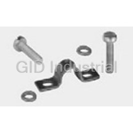
Cable Clamps and Clips Clamp Screw Steel Box 1-1106302-9
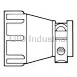
Cable Clamps and Clips Clamp Screw Thermoplastic 1-206062-0
Cable Clamps and Clips Clamp Screw Thermoplastic Individual 1-206062-1
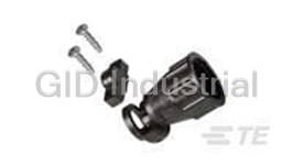
Cable Clamps and Clips Clamp Screw Thermoplastic Individual 1-206062-6
Cable Clamps and Clips Clamp Screw Thermoplastic Black Bulk 1-206062-7
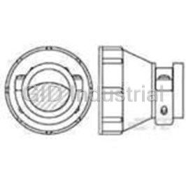
Cable Clamps and Clips Clamp Individual 1-206138-1
Request a Quote

The quote request has been received
Close

Facing challenges or have inquiries? Feel free to contact us!
Call Us +1-469-283-2440
What they say about us
FANTASTIC RESOURCE
One of our top priorities is maintaining our business with precision, and we are constantly looking for affiliates that can help us achieve our goal. With the aid of GID Industrial, our obsolete product management has never been more efficient. They have been a great resource to our company, and have quickly become a go-to supplier on our list!
Bucher Emhart Glass
EXCELLENT SERVICE
With our strict fundamentals and high expectations, we were surprised when we came across GID Industrial and their competitive pricing. When we approached them with our issue, they were incredibly confident in being able to provide us with a seamless solution at the best price for us. GID Industrial quickly understood our needs and provided us with excellent service, as well as fully tested product to ensure what we received would be the right fit for our company.
Fuji
HARD TO FIND A BETTER PROVIDER
Our company provides services to aid in the manufacture of technological products, such as semiconductors and flat panel displays, and often searching for distributors of obsolete product we require can waste time and money. Finding GID Industrial proved to be a great asset to our company, with cost effective solutions and superior knowledge on all of their materials, it’d be hard to find a better provider of obsolete or hard to find products.
Applied Materials
CONSISTENTLY DELIVERS QUALITY SOLUTIONS
Over the years, the equipment used in our company becomes discontinued, but they’re still of great use to us and our customers. Once these products are no longer available through the manufacturer, finding a reliable, quick supplier is a necessity, and luckily for us, GID Industrial has provided the most trustworthy, quality solutions to our obsolete component needs.
Nidec Vamco
TERRIFIC RESOURCE
This company has been a terrific help to us (I work for Trican Well Service) in sourcing the Micron Ram Memory we needed for our Siemens computers. Great service! And great pricing! I know when the product is shipping and when it will arrive, all the way through the ordering process.
Trican Well Service
GO TO SOURCE
When I can't find an obsolete part, I first call GID and they'll come up with my parts every time. Great customer service and follow up as well. Scott emails me from time to time to touch base and see if we're having trouble finding something.....which is often with our 25 yr old equipment.
ConAgra Foods