

 Manufacturers
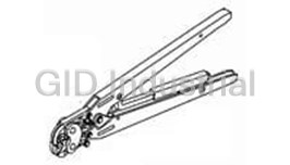
TE CONNECTIVITY 1-456134-2
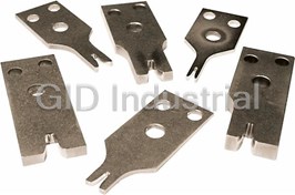
Description
Application Tooling F Crimping, Stripping
1-456134-2
Part Number
1-456134-2
Price
Request Quote
Manufacturer
TE CONNECTIVITY
Lead Time
Request Quote
Category
Tools and Supplies » Assembly Tools
Specifications
Manufacturer
TE Connectivity
Manufacturers Part #
1-456134-2
Industry Aliases
1-456134-2
Sub-Category
Electronics Assembly Tools
Brand
AMP
Factory Pack Quantity
1
Datasheet
DDEController?Action=srchrtrv&DocNm=1-1773838-7&DocType=Data+Sheet&DocLang=English&PartCntxt=3-456404-6.pdf
921 KiB

Extracted Text
CRIMP TOOLING – WHERE FORM MEETS FUNCTION The cost of quality can be expensive Introduction Quality, cost, and throughput are associated with specific It is difficult to distinguish critical tooling attributes with visual measurements and linked to process variables. Crimp height, pull inspection only. Some attributes cannot be inspected even by test values, leads per hour, and crimp symmetry are some of the running crimp samples. This paper will present the reader with measures used to monitor production termination processes. information that identifies key crimp tooling attributes and the effect of those attributes on the crimping process. Many variables affect the process such as wire and terminal quality, machine repeatability, setup parameters, and operator skill. Geometry and Associated Tolerances Crimp tooling is a significant contributor to the overall crimp Terminals are designed to perform to specification only when the termination process. The condition of crimp tooling is constantly final crimp form is within a narrow range of dimensions. monitored in production by various means. These means are often Controlling critical crimp dimensions is influenced by many factors indirect measures. Crimp Quality Monitors and crimp cross including: sections are methodologies that infer the condition of the crimp • Wire size and material variation tooling. Visual inspection of the crimp tooling can be used to check • Terminal size and material variation for gross failures such as tool breakage or tooling deformation • Equipment condition which occurred as a result of a machine crash. Continuous monitoring of production will help determine when the process The final quality and needs to be adjusted and the replacement of crimp tooling can be consistency of a one of the adjustments that is made. crimp can never be any better than the quality and consistency of the tooling that is used. If other variations could be eliminated, tooling can and should be Cross Section Defining Crimp Width, Crimp Height and Flash able to produce crimp forms that are well within specified tolerances. In addition, variation from one tooling set to another should be held to a minimum. Crimp tooling features that are well controlled and exhibit excellent consistency from tooling set to tooling set can result in shorter setup time as well as more consistent production results. Crimp tooling can a have positive effect on the quality, cost, and throughput of the termination process. High quality crimp tooling Some critical crimp characteristics are directly defined by the can produce high quality crimps with less in-process variation over tooling form and are obvious. These include crimp width & crimp a greater number of terminations. length. APPLICATION TOOLING /// WHERE FORM MEETS FUNCTION Page 1 WHERE FORM MEETS FUNCTION Other critical crimp characteristics can be related to several A typical design point for AI is 80%. In order to maintain the same tooling form features and/or other system factors. These may be AI, the crimp height, CH, needs to change inversely to the change less obvious and include: of crimp width, CW, in approximately the same proportion. Thus, if the CW increases +2%, the CH needs to change approximately - • Flash 2% in order to achieve the same AI design point. At first glance • Roll, twist, and side-to-side bend that may not seem significant, but in reality it can be very • Up/down bend significant. Using another general industry design rule of the ratio • Crimp symmetry of CH to CW of approximately 65%, a typical set of dimensions • Bellmouth used as an example may be: CW = 0.110 in, CH = 0.068 in The following discussion focuses on two characteristics, crimp width and flash, as examples of how tooling affect crimp form. Therefore, varying the CW by 2% would result in a CH variation of Similar arguments can be applied to the others. 2%, or 0.0014 in. At a CH tolerance of ± 0.002 in, 35% of the total Crimp Width CH tolerance would be used by a 2% variation in CW. Thus, the importance of crimp width control is obvious when tooling is Crimp width is a good example of a feature that should be changed during a production run. consistent and in control between different crimpers of the same part number. The reason for this is quite straightforward. For a given terminal and wire combination, it is necessary to achieve an area index, AI, which is determined by the terminal designer for optimal mechanical and electrical performance. Crimp height, CH, and crimp width, CW, directly affect achieving proper AI. Area index, AI (as a percentage), is defined as: (a) where A is the total area of the wire and barrel after crimping. A t W and A are, respectively, the initial cross-sectional areas of the B wire and barrel before crimping. (b) APPLICATION TOOLING /// WHERE FORM MEETS FUNCTION Page 2 WHERE FORM MEETS FUNCTION Flash Most crimp terminations have a requirement to limit flash. Flash is The following is offered as an example: defined as the material which protrudes to the sides of the terminal down and along the anvil. Flash is normal in the crimping process but excessive flash is very undesirable. Controlling flash Nominal condition: CH = 0.073 in, CW = 0.110 in requires a balance of several geometric factors. Other factors Crimper leg taper = 3.0 degree influencing flash are related to surface finish and friction, which will be discussed later in this paper. Anvil Width = 0.109 in A dominant factor in controlling flash is controlling the clearance Nominal anvil to crimper total clearance = 0.005 in between the crimper and anvil during the crimp process. Defining The clearance can grow rapidly with small changes to the the ideal clearance could in itself be a simple matter were it not nominal dimensions: for two facts: CH remains unchanged = 0.073 in • In order to minimize terminals’ sticking in the crimper, the sides of the crimper are tapered. Thus the Increase in crimp width, CW, = 0.0008 in clearance between the anvil and crimper varies Increase in crimper leg taper = 0.8 degree throughout the stroke. • Crimper and anvil sets are typically designed to Decrease in anvil width = 0.0008 in terminate two to four wire sizes. This creates multiple The increase in total clearance is this case = 0.0026 in crimp heights. Since the sides of the crimper are tapered to minimize terminal sticking, the maximum This is more than a 50% increase in the nominal design clearance permitted without creating flash must be clearance, which can result in unacceptable flash assigned to the maximum crimp height specified for the Dimensional control is clearly critical. tooling set. In addition, a minimal clearance must be maintained for the smallest crimp height specified by the tooling set to prohibit contact between the anvil and crimper. Significant flash can be generated with excessive anvil to crimper clearance, as shown by nominal design condition (a) (a) and +0.003 in over nominal condition (b) (b) Crimper to anvil clearance is thus a combination of crimp width, crimper leg taper, anvil width, and crimp height. The critical design point is at the largest crimp height. This contribution to the gap is directly dependent on dimensional control. APPLICATION TOOLING /// WHERE FORM MEETS FUNCTION Page 3 WHERE FORM MEETS FUNCTION Materials suitable and are well described in the material handbooks. It is the processing of these materials that can make a significant The material selection for tooling is critical. The material must be performance difference. able to meet the in-service demands placed on the tooling components. The two critical tooling components to be reviewed In order to withstand the rapid loading to a high stress on a are the wire crimper and the anvil. repeated basis, the surface of the material must minimize cracks and imperfections that may be generated during the machining The wire crimper and the anvil have different functional demands. and/or heat treat operations. It is important that grain structure be Both have the need to withstand high loads and moderate shock. controlled in size and orientation to achieve maximum and However, the wire crimper is in fact an aggressive forming tool. It consistent service life. Decarburization of the surface during heat must withstand high shear loading that is a result of frictional treating must be controlled. Heat treating process controls are loads generated as the terminal barrel slides along the crimper critical to reproducing the optimal surface. Machining processes surfaces in the forming process, and then as the terminal barrel is must also be controlled to avoid surface cracking due to plastically deformed and extruded to complete the termination. excessive heat generation during overly aggressive material The anvil experiences some of the same conditions but to a much removal. Likewise, localized tempering may occur, which can lower level of severity. soften material beyond the effective range. The wire crimper and the anvil can be likened to a punch and die These variations in final material and surface conditions are not in the world of metalworking. The materials used in punch and die readily detectable with a visual inspection. They can manifest applications have been well documented, along with the material themselves during service and result in unacceptable tooling selection process. The added severity of the aggressive forming performance. and the terminal and wire extrusion during crimping add complexity to the material selection. The material selection Wear Resistance process involves: Wear is generally described as the gradual deterioration of a • Strength of materials with emphasis on toughness needed surface through use. Several types of wear exist and include to withstand the moderate shocks generated during adhesive, abrasive, and pitting. By design, the tooling is able to crimping withstand normal surface loads. Thus, pitting is typically not an • Wear resistance to maintain form issue. In addition to the above design considerations, there exists The primary wear mode experienced by crimp tooling is adhesive another phenomenon that occurs during crimping that can wear. Adhesive wear occurs as two surfaces slide across each significantly shorten the useable life of a wire crimper. Material other. Under load, adhesion, sometimes referred to as cold can be transferred from the terminal barrel to the wire crimper. welding, can occur. Wear takes place at the localized points of This material buildup can result in unacceptable terminations. The adhesion due to shear and deformation. Adhesion is highest at crimped terminal surfaces can actually be deformed by the the peaks of surface finish because that is where the load is indentations of the deposited material. Crimp deformation may greatest. During crimping, the ideal conditions exist for adhesive result due to increased friction. Tooling wear can be accelerated wear. That is, due to higher crimp forces. Surface treatments that minimize this • High loading due to crimp force material transfer are critical to extended tooling life. • Sliding surfaces due to crimp formation, and terminal and Strength of Materials wire extrusion Crimpers and anvils are designed to be able to withstand stresses Wear will generally manifest itself more significantly at edges of a that are typically encountered during crimping. The basic design surface. However, adhesive wear is often observed over of tooling with reference to size and geometry has been well substantial areas of the tooling. It is important to note here that analyzed and generally stresses generated during crimping are the wire crimper is the component most susceptible to adhesive able to be accommodated. However, there are always demanding wear. Generally, adhesive wear will be directly related to load and applications that will tax the design to its stress limits. In those to the amount of relative movement between the two materials. cases, geometry and material may depart from the standard Although the anvil may have equal loading, the amount of relative design. These exceptions are dealt with on a one-by-one basis movement between the terminal and tooling is many times more and will not be discussed here. at the crimper than at the anvil. The insulation crimper typically experiences lower adhesive wear because the load is reduced It is the unique requirement of stress and shock that needs to be compared to the wire crimp and the relative movement is less discussed. Peak crimp loads go from zero to maximum in less than that of the wire crimper, since there is no terminal and wire than 40 ms. Tooling needs to withstand this load cycle at a rate of extrusion at the insulation crimp. greater than once per second. Several classes of tool steels are APPLICATION TOOLING /// WHERE FORM MEETS FUNCTION Page 4 WHERE FORM MEETS FUNCTION Adhesive wear can be controlled in the selection of the material. Surface Condition Different alloys exhibit better or worse wear properties. These Surface condition can affect the performance of the crimp tooling properties can be measured and are well documented. Adhesive as well as the longevity of service. As noted in the previous wear is inversely proportional to the hardness of the material. section, a hard, smooth surface has improved adhesive wear Thus, the harder the material, the less adhesive wear. In crimp properties and, thus, longer service life. The other attribute that tooling, there is often a tradeoff that is made. In order to achieve needs to be considered is friction. higher wear resistance, the material often exhibits lower toughness by composition, hardness, or both. The final material Friction is a contributing factor in determining the final crimp form selection is often based on years of experience. One material and process characteristics. Low tooling friction results in lower may have high wear characteristics and lower toughness, and be crimping force and thus can influence crimp form as well as suitable for a small terminal since the margin of safety on stress is tooling life. Consistent frictional characteristics between tooling high. Another terminal may be large and the toughness could be sets will result in reduced process variation. of more importance due a lower stress design margin. The ability Friction of the crimp tooling surfaces is influenced by factors to design and manufacture crimpers from several materials will similar to those that influence adhesive wear—hardness and enable optimal material selection for a specific application. surface finish. Generally, harder materials exhibit lower The final property that affects adhesive wear is surface finish. As coefficients for sliding friction. Friction coefficients have also been stated earlier, adhesion is highest at the peaks of the surface. shown to be related to surface finish. Manufacturing processes Thus, the smoother the finish, the less significant the peaks and need to produce consistent results such that when tooling sets the less significant the adhesion. Adhesive wear can be reduced need to be changed in production, minimum disruption in crimp with a lower surface finish. Surface finish affects other crimping quality is achieved. It has been found that maintaining surface performance parameters. These are discussed in the next hardness above Rc 55 as well as keeping surface finishes to 8 section. micro-inches or less is desirable to obtain consistent crimp results and minimize adhesive wear. Abrasion can occur depending on terminal surfaces. If a terminal is plated with an abrasive substance, the tooling could suffer from abrasive wear. This would be an atypical condition and would be handled by special design. Other applications where abrasive wear is the primary wear mode involve terminals made of steel and stainless steel. Extensive testing has shown chromium plating is the best surface treatment that can be used on crimpers designed for these abrasive terminals. However, in these applications, crimpers will not last as long as those crimpers used to crimp terminals made of other, less abrasive base materials. Using a lubricant (in those applications where this is acceptable) has shown to increase the life of the crimper. However, even when lubricated the crimper life can be expected to be shorter when crimping steel or stainless steel terminals. Once abrasive wear has taken place to the point where the chromium plating has been removed from the base tool steel of the crimper, as successive crimp cycles occur, further wear will happen very quickly. Without the protective chromium plating, the underlying surface will then be subject to either further abrasive Typical Effect of Friction on Crimp Force wear, or adhesive wear. For this reason, care should be taken to replace the crimper as soon as wear is visible on the surface of the crimper. APPLICATION TOOLING /// WHERE FORM MEETS FUNCTION Page 5 WHERE FORM MEETS FUNCTION Surface Treatment Chromium plated crimper Surface condition can affect the performance of the crimp tooling surface after 100,000 as well as the longevity of service. A hard, smooth surface has terminations. Note there improved adhesive wear properties and, thus, longer service life. is no visible buildup of material. The other attribute that needs to be considered is friction. A commonly accepted approach to improved crimp tooling performance and life has been to apply a surface treatment to the crimp area. The wire crimper has been defined in previous Unplated crimper surface after 60,000 terminations. discussions as tooling component that is subjected to the Note significant buildup severest duty cycle. Thus, applying an appropriate surface of material. treatment to the wire crimper will have the most benefit to crimp performance and tooling life. These treatments can include hard metal plating or ceramic coating. Gross deformation of An example of a treatment that has been successful in achieving crimped terminal significant level of performance and life improvements is hard resulting from material chromium plating. buildup in crimper. Chromium plating has a very low coefficient of friction. As noted, friction has a significant effect on crimp form. The static and sliding coefficients of friction for steel on steel are typically 0.30 Visible deformation of and 0.20 respectively. Chromium plated steel on steel can reduce outer crimp surface the static and sliding coefficients to 0.17 and 0.16. because of indentation from material buildup on Chromium plating also reduces wear resistance. Adhesive wear crimper. resistance is improved as surface hardness improves. Chromium plating typically exhibits a hardness Rc 65+. This hardness level greatly enhances resistance to adhesive wear. This now frees up Chromium plating has the ability to be applied uniformly and the designer to consider more base metal options. A base consistently and exhibits excellent adhesion to the base metals. material of reduced wear resistance but greater toughness can be The unique benefits of chromium plating, such as ease of selected and its wear resistance improved with chromium plating. application, consistency of plating, adhesion to base metal, Thus, chromium plating can enable a better tooling solution for extremely low coefficient of friction, very high hardness, and the crimp production process. resistance to adhesion, make it truly difficult to match in crimp Perhaps one of the most significant effects of chromium plating, is performance and durability. However many alternative coatings its resistance to adhesion and cold welding. A side effect of are being attempted, and some show excellent promise in specific adhesive wear is the transfer of material from the terminal to the applications. wire crimper. By definition, adhesive wear is caused by material Summary adhering to localized points on the surface. Some of the adhesion results in the surface material being worn away and some in the This paper has explored four categories of characteristics that are transfer of material from the terminal to the crimper. As more key to high performance tooling. Several examples have been cycles occur, more material is transferred. Thus there a resultant discussed which demonstrate how minor variations in those buildup of terminal material on the crimper. characteristics can have measurable and sometimes significant effects on the resultant crimp form and its compliance to This buildup will result in two potentially catastrophic failures: specifications. These same characteristics can affect tooling • The built-up material will create deformations in the terminal service life. It is also a logical extension of these discussions to surface, resulting in unacceptable crimps. conclude that variations of these characteristics from one tooling • Crimps will be greatly distorted due to significant changes set to another tooling set can affect process control when tooling in the friction factor and result in terminals not conforming changes are required in production. Maintaining process control to the desired form. Unacceptable crimp forms, such as may require additional setup time. Quality tooling that addresses unsymmetrical cross-section, excessive flash, and open the key characteristics of geometry, materials, surface condition, barrels can result. and surface treatment is an important component of your total quality control program. APPLICATION TOOLING /// WHERE FORM MEETS FUNCTION Page 6 WHERE FORM MEETS FUNCTION APPLICATION TOOLING /// WHERE FORM MEETS FUNCTION Page 7 te.com TE Connectivity, TE Connectivity (logo) and Every Connection Counts are trademarks. All other logos, products and/or company names referred to herein might be trademarks of their respective owners The information given herein, including drawings, illustrations and schematics that are intended for illustration purposes only, is believed to be reliable. However, TE Connectivity makes no warranties as to its accuracy or completeness and disclaims any liability in connection with its use. TE Connectivity‘s obligations shall only be as set forth in TE Connectivity‘s Standard Terms and Conditions of Sale for this product and in no case will TE Connectivity be liable for any incidental, indirect or consequential damages arising out of the sale, resale, use or misuse of the product. Users of TE Connectivity products should make their own evaluation to determine the suitability of each such product for the specific application. © 2018 TE Connectivity Ltd. family of companies All Rights Reserved. 1-1773838 7 03/18 Original APPLICATION TOOLING /// WHERE FORM MEETS FUNCTION Page 8
Frequently asked questions
How does Electronics Finder differ from its competitors?

Is there a warranty for the 1-456134-2?
Which carrier will Electronics Finder use to ship my parts?
Can I buy parts from Electronics Finder if I am outside the USA?
Which payment methods does Electronics Finder accept?
Why buy from GID?

Quality
We are industry veterans who take pride in our work

Protection
Avoid the dangers of risky trading in the gray market

Access
Our network of suppliers is ready and at your disposal

Savings
Maintain legacy systems to prevent costly downtime

Speed
Time is of the essence, and we are respectful of yours
Related Products

Torque Wrenches Are Used To Properly Install Or Disassemble The Connectors 1055419-1
Tool For RF Connectors 1055442-1
Tool For RF Connectors 1055443-1
Insertion Tool For RF Connectors 1055447-1
Insertion Tool For RF Connectors 1055448-1
Assembly Tools, Sma Right Angle Cable Plugs 1055451-1
Request a Quote

The quote request has been received
Close

Facing challenges or have inquiries? Feel free to contact us!
Call Us +1-469-283-2440
What they say about us
FANTASTIC RESOURCE
One of our top priorities is maintaining our business with precision, and we are constantly looking for affiliates that can help us achieve our goal. With the aid of GID Industrial, our obsolete product management has never been more efficient. They have been a great resource to our company, and have quickly become a go-to supplier on our list!
Bucher Emhart Glass
EXCELLENT SERVICE
With our strict fundamentals and high expectations, we were surprised when we came across GID Industrial and their competitive pricing. When we approached them with our issue, they were incredibly confident in being able to provide us with a seamless solution at the best price for us. GID Industrial quickly understood our needs and provided us with excellent service, as well as fully tested product to ensure what we received would be the right fit for our company.
Fuji
HARD TO FIND A BETTER PROVIDER
Our company provides services to aid in the manufacture of technological products, such as semiconductors and flat panel displays, and often searching for distributors of obsolete product we require can waste time and money. Finding GID Industrial proved to be a great asset to our company, with cost effective solutions and superior knowledge on all of their materials, it’d be hard to find a better provider of obsolete or hard to find products.
Applied Materials
CONSISTENTLY DELIVERS QUALITY SOLUTIONS
Over the years, the equipment used in our company becomes discontinued, but they’re still of great use to us and our customers. Once these products are no longer available through the manufacturer, finding a reliable, quick supplier is a necessity, and luckily for us, GID Industrial has provided the most trustworthy, quality solutions to our obsolete component needs.
Nidec Vamco
TERRIFIC RESOURCE
This company has been a terrific help to us (I work for Trican Well Service) in sourcing the Micron Ram Memory we needed for our Siemens computers. Great service! And great pricing! I know when the product is shipping and when it will arrive, all the way through the ordering process.
Trican Well Service
GO TO SOURCE
When I can't find an obsolete part, I first call GID and they'll come up with my parts every time. Great customer service and follow up as well. Scott emails me from time to time to touch base and see if we're having trouble finding something.....which is often with our 25 yr old equipment.
ConAgra Foods