

 Manufacturers
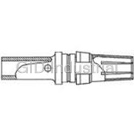
TE CONNECTIVITY 100081-1
Description
Contact SKT Solder ST Cable Mount 8AWG Loose
100081-1
Part Number
100081-1
Price
Request Quote
Manufacturer
TE CONNECTIVITY
Lead Time
Request Quote
Category
Connectors » Connector Contact
Specifications
Manufacturer
TE Connectivity
Manufacturers Part #
100081-1
Industry Aliases
100081-1
Sub-Category
Connector Contacts
Brand
AMP
Packaging
Loose
Factory Pack Quantity
10
Datasheet
DDEController?Action=srchrtrv&DocNm=65911&DocType=DS&DocLang=English&s_cid=1046.pdf
2423 KiB

Extracted Text
AMP Z-PACK 2mm HM Hard Metric Interconnection System AMP Z-PACK 2mm HM Hard Metric Interconnection System Tyco Electronics — Committed to Customer Service Disclaimer While Tyco Electronics Corporation APPLICATION FORM FOR TYCO ELECTRONICS MODELLING SERVICES and its affiliates referenced herein Photocopy this form, complete it and fax it to Tyco Electronics to apply for usership of the Tyco Electronics Modelling Services (“Tyco Electronics”) have made every reasonable effort to ensure the accuracy of the information in this catalog, Tyco Electronics does not guarantee that Name: Job Title: it is error-free, nor does Tyco Electronics make any other representation, warranty Company Name: or guarantee that the information is accurate, correct, reliable or current. Company Address: Tyco Electronics reserves the right to make any adjustments to the information contained herein at any time without notice. Tyco Electronics expressly dis- claims all implied warranties regarding the information contained herein, includ- ing, but not limited to, any implied war- Post/Zip code: ranties of merchantability or fitness for a particular purpose. Tyco Electronics’ Tel Number: Fax Number: only obligations are those in the Tyco Electronics Standard Terms and I understand that the data provided by Tyco Electronics on CD-ROM remains the property of Tyco Electronics Corporation. Conditions of Sale, and in no case will Tyco Electronics be responsible for any incidental, indirect, or consequential Signature: damages arising from the sale, resale, use, or misuse of its products. Users Fax this form, when completed, to: The Modelling Services Administrator at your nearest Tyco Electronics should independently evaluate the suit- ability of, and test each product for, their local company (see inside back cover for fax #). application. The dimensions, specifications, designs, construction, materials and processes in Electrical Performance Reports this catalog are for reference purposes Find products fast on the web Comments on using this only and are subject to change without 65721 5 row Connector catalog Tyco Electronics has devel- notice. Please consult Tyco Electronics 65722 5+2 row Connector for the most current product information. oped a user-friendly and Dimensions are in millimeters 889065 8 row Connector The export of certain Tyco Electronics dynamic search technique and inches. Values in brack- products is restricted by the Arms 889066 8+2 row Connector that allows you to steer the ets are inch equivalents. Export Control Act (Title 22, U.S.C. search for the product you Dimensions used in this Sec 2751, et seq.) or the Export need. Our electronic cata- catalog are for reference Need more information? Administration Act of 1979, as amended (Title 50, U.S.C., App. 2401 et seq.). log allows you to access purposes only. Customer Call Technical Support at the Orders may be subject to export drawings, specifications drawings are available on numbers listed below. approval by the U.S. Government. Buyer and part number details. request. Metric symbols must comply with all applicable export Technical Support is staffed Languages available used are: laws of all applicable jurisdictions. with specialists well versed include English, Spanish, m= meter in Tyco Electronics products. French, German and Italian. cm = centimeter Tyco Electronics Modelling They can provide you with: A few, quick registration mm = millimeter Services details are all it takes: ■ Technical support µm = micrometer As a service to our cus- ■ Catalogs N= Newton http://connect. tomers, Tyco Electronics ■ Technical Documents kg = kilogram has developed CD-ROM- tycoelectronics.com g= gram ■ Product Samples based 2D and 3D CAD C= Celsius ■ Authorized Distributor IGES models. These are Locations Friendly advice at the end easily transferred into your Technical documents designs, saving you costly of the telephone © 1999 and 2005 by Tyco Electronics time when defining your Product Specifications Corporation. If all of the above cannot product. Use the applica- All International Rights Reserved. 108-19082 5 row board-to-board help, we have a team of tion form above to apply for Connections AMP, AMP-HDI, ACTION PIN, Z-PACK experts in our Product and Tyco are trademarks. your ‘PIN’ number. 108-1622 8 row board-to-board Information Centers ready CompactPCI is a trademark of Connections to assist you with technical PICMG-PCI Industrial Computer 108-19107 LF Cable Connectors information and help identify Manufacturers Group Incorporated. 108-19108 HF Cable Connectors the right products for your LOCTITE is a trademark of Henkel Corp. 108-1651 Universal Power Module needs. RAL is a trademark of the Central Organization for product assurance in Application Specifications Germany. 114-19029 Standard board-to-board Other products, logos, and company 114-19036 Ground Return Shields names mentioned herein may be trademarks of their respective owners. 114-19039 LF Cable Connector See inside back cover for Global 114-1103 Universal Power Module Contacts and phone numbers. 2 Catalog 65911 Dimensions are in millimeters Dimensions are shown for USA: 1-800-522-6752 South America: 55-11-3611-1514 Revised 7-05 and inches unless otherwise reference purposes only. Canada: 1-905-470-4425 Hong Kong: 852-2735-1628 specified. Values in brackets Specifications subject Mexico: 01-800-733-8926 Japan: 81-44-844-8013 www.tycoelectronics.com are standard equivalents. to change. C. America: 52-55-5-729-0425 UK: 44-141-810-8967 AMP Z-PACK 2mm HM Hard Metric Interconnection System Product Outline and Table of Contents Product Facts Product Outline ■ High Density System with The AMP Z-PACK 2mm HM Table of Contents Small Real Estate on Hard Metric connector sys- Specifications .........................................................2 Backplane and Daughtercard tem is designed to meet the ■ Extensive Range of Signal, current and future needs System Options, Front and Rear ......................4, 5 Power, Coaxial, and Fiber of telecommunication, Board-to-Board and Cable- Product Characteristics and System Features ...6 computer and instrumenta- to-Board Connections. tion applications giving Electrical Characteristics ......................................7 ■ Hard Metric 2mm Pitch in excellent electrical and Accordance with IEC 917 mechanical characteristics Contact Make and Break Sequence .....................8 and IEC 61076-4-101 at an economical price. It is Connector Configurations.....................................9 a high performance, high ■ Modular Units give Flexible Configuration density system with flexible Vertical Male Connectors, 5 row....................10-12 configuration which offers ■ Special Versions for VME64 Right Angle Female Connectors, 5 row ........13-15 upgradeability. The connec- Extensions and CompactPCI tor system is fully sup- ■ Signal Contact Rating 1.5a Vertical Male Connectors, 8 row....................16-18 ported by Tyco Electronics Fully Energized spice models to guarantee Right Angle Female Connectors, 8 row ........19-21 ■ Universal Power Module choosing the right product rated at 7.8A / line, 23.4A 4 & 4+1 Row Slim Connectors ......................22, 23 to match the application. fully energized Vertical Female Connectors, 8 Row ...................24 Z-PACK 2mm HM connec- ■ All Lines Impedance tors comply with the Controlled to 50ohm Right Angle Male Connectors, 5 Row ..........25, 26 requirements of IEC 917 (Single Ended) and 100ohm and IEC 61076-4-101 and Vertical Female Connectors, 5 Row ...................27 (Differential) nominal valuable product extensions ■ Safe Design, complies with Midplane Board-to-Board Arrangements...........28 provide great flexibility in IEC950 in Mated Condition; Male Shrouds (ZIF Style) ..................................29 the range of applications. Universal Power Module is Spacers .............................................................30 The system can provide the Safe in Unmated Condition Spacer Selection ...............................................31 following options: ■ Several Performance Levels One Piece Shrouds ...........................................32 for Board and Cable ■ Backplane and Male Pin Protection Covers...............................33 Connectors with Unshielded daughtercard and Shielded Versions connections in standard DIN and Hybrid DIN Systems.........................34-40 ■ Corruption-proof and reverse sex. AMP Mini-SC (MSC) and sequencing- Signal Contact ■ Parallel daughtercard Levels exceed Maximum Hybrid MSC Systems .................................41-46 connection. Tolerance of Backplane Coding Keys and Contact Loading Variants......47 ■ Midplane connections in Distortion and Warpage both planar and cross (ref. Hard Metric Equipment CompactPCI and VME 64 Extensions.................48 connect configuration. Practice) CompactPCI Connectors: At a Glance.........49, 50 ■ Mismatching Keys Block ■ Cable connections for Mating before any Contact backplane rear and front Universal Power Module.................................51-53 Touch of daughtercards. Guiding Hardware ...........................................54-57 ■ Backplane thickness range ■ Extender card connections. 1.4 - 5.6 [.055 - .220] Cable Connectors and Lead Assemblies...........58 These variations can be ■ Daughtercard Thickness Cable Connector Mating Arrangements ............59 arranged for signal contacts, Range of 1.4 - 4.3 [.055 - 10 and 20 Position Connectors .........................60 and for backplanes, power, .169] (3.5 [.138] max. with Lead Assemblies ...............................................61 coax and fiber optic cable Lower Shields) and board connections. Male Cable Connector Shrouds ........................62 ■ Small Press Fit Board Hole Male Connectors, Cable-to-Board...............63, 64 allows Maximum Track Width and Minimum Signal Dimensions and Tolerances ..........................65, 66 Corruption Customer Specification Chart.............................67 ■ Versions comply with Bellcore Central Office PC Board Layouts ...........................................69-72 Environment and Uncontrolled Environment Connector Insertion Tooling ..........................73-77 ■ Single- and Multi-line Non-RoHS to RoHS Compliant Models Available or Part Number Cross Reference ..................78-80 Tyco Electronics Circuits & Design can build a System Part Number Index .........................................81, 82 to your Specification 3 Catalog 65911 Dimensions are in millimeters Dimensions are shown for USA: 1-800-522-6752 South America: 55-11-3611-1514 Revised 7-05 and inches unless otherwise reference purposes only. Canada: 1-905-470-4425 Hong Kong: 852-2735-1628 specified. Values in brackets Specifications subject Mexico: 01-800-733-8926 Japan: 81-44-844-8013 www.tycoelectronics.com are standard equivalents. to change. C. America: 52-55-5-729-0425 UK: 44-141-810-8967 AMP Z-PACK 2mm HM Hard Metric Interconnection System System Options — Front Parallel Card Connection Pages 10 and 26 5 and 5+2 Row Pages 10-15 Card Extenders Pages 24, 25 Power, Coax and Fiber Optic Systems Pages 34-46 Cable Headers Pages 63, 64 Reverse Sex Connection Dimensions Between Boards Pages 25-27 Daughtercard to backplane dimension 12.5 [.492] except for reverse sex which is 17.7 [.700]. Stacked daughtercard spacing is 15.0 [.591]. Minimum spacing between daughtercards is 16.0 [.630] (18.0 [.709] for cable connectors; 20.0 [.787] for EMI/RFI shield systems; 24.0 [.945] for 8 and 8+2 row systems). Universal Power Card extender spacing 15.0 [.591]. 8 and 8+2 Row Module and See Application Specification 114-19029 Pages 16-24 Guide Pins for details and tolerances. Pages 51-57 4 Catalog 65911 Dimensions are in millimeters Dimensions are shown for USA: 1-800-522-6752 South America: 55-11-3611-1514 Revised 7-05 and inches unless otherwise reference purposes only. Canada: 1-905-470-4425 Hong Kong: 852-2735-1628 specified. Values in brackets Specifications subject Mexico: 01-800-733-8926 Japan: 81-44-844-8013 www.tycoelectronics.com are standard equivalents. to change. C. America: 52-55-5-729-0425 UK: 44-141-810-8967 AMP Z-PACK 2mm HM Hard Metric Interconnection System System Options — Rear Shrouds & Spacers Pages 29-32 Cross Connect Page 28 AMP Mini-SC (MSC) Fiber Optic Connectors Pages 41-46 Cable Headers & Shrouds Pages 62-64 Cable Connectors & Assemblies Pages 58-61 5 Catalog 65911 Dimensions are in millimeters Dimensions are shown for USA: 1-800-522-6752 South America: 55-11-3611-1514 Revised 7-05 and inches unless otherwise reference purposes only. Canada: 1-905-470-4425 Hong Kong: 852-2735-1628 specified. Values in brackets Specifications subject Mexico: 01-800-733-8926 Japan: 81-44-844-8013 www.tycoelectronics.com are standard equivalents. to change. C. America: 52-55-5-729-0425 UK: 44-141-810-8967 AMP Z-PACK 2mm HM Hard Metric Interconnection System Product Characteristics and System Features Product Characteristics System Features Electronic developments are Shielding Termination Coaxial Connection increasing the demands on Upper and/or lower ground All versions use DIN coax contacts can be system performance, and return shields are used with AMP ACTION PIN press fit fitted to type L, M and N connectors can no longer 5+2 and 8+2 row headers contacts, giving high reten- housings in cable and be considered as discrete to improve signal integrity. tion force termination con- board mount versions. components but as part of a EMI / RFI shields are avail- forming to IEC 352-5. Fiber Optic Connections total electrical/electronic able to totally enclose 5 row Pin Headers DIN style contacts can design. These aspects can connectors to give maxi- Contact pins are available be fitted to housings as include the following: mum immunity from, and to give three mating levels above or higher density minimum emission of, radi- Higher pin count within tight on the front face with stan- AMP MSC contacts to MSC ated noise. space constraints. dard 3.7 [.146] tail, suitable housings. Reduced Skew for boards from 1.4 to 4.3 With 25 and 40 signal pins Spice Models The design of right angle [.055 - .169] thick. per cm of 5 row and 8 row To achieve optimum connectors achieves very Feedthrough vertical head- connectors respectively, high performance and cost, low skew between longest ers offer three levels of mat- densities can be achieved, it is essential to accurately and shortest contact and ing to rear of backplane for or low signal to ground match connector and board paths, corrected for midplane and cable con- ratios specified within tight system parameters. Where board effects. The actual nection with special twisted space constraints. customers wish to carry value varies between 5 row pins used for cross connect out their own analysis, Minimum reflections and 8 row types. applications. A wide variety Tyco Electronics offers sin- Matched impedance of standard product exists Fiber Optic Connections gle and multi-line models between cables, connectors which offer economy and As well as the normal for many connector styles. and systems give low reflec- short lead times, but any power and coaxial DIN con- Please ask for details of the tions at interfaces. This is variation of selective load tacts, either DIN fiber optic packages available. achieved with overmolded can be offered. or AMP MSC fiber optic receptacle contacts which Modelling Support connectors can be included Receptacle Assemblies give impedances close to Tyco Electronics offers a in backplane systems for Receptacle assemblies the values of printed circuit structured approach to the high speed data transfer employ a 'chiclet' assembly boards, maximizing effec- design and evaluation of without risk of corruption. principle allowing a variety tive signal strength. packaging and intercon- of selective loading and Upgradeability nection systems, including Reduced crosstalk providing the ability to fit The system is upgradeable a full range of electrical Crosstalk can be minimized reduced cross talk shields. to give enhanced perform- and mechanical support by selective use of ground Enhanced versions are pre- ance as system demands functions. pins between signals, fitted with upper shields, increase. This allows eco- which can be augmented Using accurate device with lower shields applied nomical selection of compo- by the use of ground return models, our capabilities separately as required. nents initially with enhanced shields. Reduced cross talk include high speed signal version selectable as per- Power Connection versions of the receptacle propagation analysis using formance levels increase Universal Power Module connector provide partial SPICE modelling, and simu- without a major change in Connectors are press fit shielding between columns. lation of interconnections connector design or board three position connectors and backplane designs. layout. Tyco Electronics rec- with the option of three Complete power distribution ommends that board layouts levels of sequencing and and thermal analysis can include ground return shield 23A rating. also be included. holes for future-proofing. Alternatively, DIN contacts System Manufacture can be used in type L ,M Tyco Electronics Circuits and N housings with con- and Packaging Division tact rating up to 40A and specializes in the design first make/last break option. and manufacture of high Variations of cable-to- performance backplanes board, board-to-board and and subsidiary boards. cable-to-cable are offered. They will design back- planes and boards to meet your performance criteria, bringing their experience and tools to enhance your design. Ask Tyco Electronics for further details. 6 Catalog 65911 Dimensions are in millimeters Dimensions are shown for USA: 1-800-522-6752 South America: 55-11-3611-1514 Revised 7-05 and inches unless otherwise reference purposes only. Canada: 1-905-470-4425 Hong Kong: 852-2735-1628 specified. Values in brackets Specifications subject Mexico: 01-800-733-8926 Japan: 81-44-844-8013 www.tycoelectronics.com are standard equivalents. to change. C. America: 52-55-5-729-0425 UK: 44-141-810-8967 AMP Z-PACK 2mm HM Hard Metric Interconnection System Electrical Characteristics Electrical Characteristics, Electrical characteristics, Typical. Typical Signal Pin rating, all contacts loaded 1.5a @ 70°C [158°F] Nominal resistance <13.5mOhm AMP Z-PACK 2mm HM Creepage/clearance 65dB (APC) >35dB (PC) Standard Operating Temp. -20/+70° Celsius [-68/+158°F] Same Type L-MSC 106743-1 Cable Pull Force >70N 2.0mm cable Same Type M-MSC 106745-1 Mechanical Endurance 500 Mating/dematings Same Type M-MSC rev 106747-1 41 Catalog 65911 Dimensions are in millimeters Dimensions are shown for USA: 1-800-522-6752 South America: 55-11-3611-1514 Revised 7-05 and inches unless otherwise reference purposes only. Canada: 1-905-470-4425 Hong Kong: 852-2735-1628 specified. Values in brackets Specifications subject Mexico: 01-800-733-8926 Japan: 81-44-844-8013 www.tycoelectronics.com are standard equivalents. to change. C. America: 52-55-5-729-0425 UK: 44-141-810-8967 AMP Z-PACK 2mm HM Hard Metric Interconnection System Type L-MSC, M-MSC & M-MSC-rev Male Connector, for MSC Fiber Optic Plugs and Signal Contacts (Continued) 15.4 Type L-MSC [.606] Cavities A B C D 49.9 [1.965] E F G H Type M-MSC Press-fit Fixing Pegs (3x) Type M-MSC-rev Polarizing Same as M-MSC, with Peg 26.4 signal contacts in columns [1.039] 1 ... 11 as shown below. 12.4 13.45 [.488] [.530] End View of Type M-MSC 15.40 zf [.606] Cavities Rows | abcde| Columns 1 2 A 3 4 5 B 6 7 C 8 9 D 10 11 49.9 [1.965] Columns Cavities 15 16 E 17 18 F 10 x 2.0 19 20 = 20.0 21 [.787] G 22 0.95 23 [.037] H 24 25 M-MSC-rev Rows abcde z f 6 x 2.0 = 12.0 [.472] 42 Catalog 65911 Dimensions are in millimeters Dimensions are shown for USA: 1-800-522-6752 South America: 55-11-3611-1514 Revised 7-05 and inches unless otherwise reference purposes only. Canada: 1-905-470-4425 Hong Kong: 852-2735-1628 specified. Values in brackets Specifications subject Mexico: 01-800-733-8926 Japan: 81-44-844-8013 www.tycoelectronics.com are standard equivalents. to change. C. America: 52-55-5-729-0425 UK: 44-141-810-8967 AMP Z-PACK 2mm HM Hard Metric Interconnection System Type L-MSC, M-MSC & M-MSC-rev Female Connector, for MSC Fiber Optic Plugs and Signal Contacts AMP MSC Housings MSC fiber optic system provides increased density compared with DIN fiber optic contacts. Contacts float within the housing and are self aligning, and apply no force to the backplane. These housings mate with those shown on page 41. MSC series housings provide 4 or 8 cavities for these connectors. M-MSC and M-MSC reverse have 55 receptacle contacts and 4 fiber optic cavities; L-MSC have 8 fiber optic cavities. Housings are press fitted to boards before installing fiber contacts. Limited other receptacle contact arrangements are possible, see page 47 for available versions. Use the chart on page 67 if your needs cannot be met from these. Performance Data pages 6-7. Materials and Finish Glass filled polyester housing, gray, UL94 V-0 rated. Phosphor-bronze signal contacts Contact area 0.8µm [.000030] Au over 1.3µm [.000050] Ni ACTION PIN Contact 0.5µm [.000020] Sn/Pb over 1.3µm [.000050] Ni Type M-MSC, M-MSC-rev and L-MSC, 50mm Modules for AMP MSC Miniature Fiber Optic Plugs MSC Board Plug, see page 46. These modules provide 4 and 8 cavities for AMP MSC fiber optic plugs, bringing increased density of connections, also zero force on backplane when fully mated. Board layout page 72 for guidance Type M-MSC and M-MSC-rev have 4 cavities for MSC fiber optic plugs, with only. 55 signal contact positions. Type L-MSC, illustrated, has 8 cavities. All Types have polarized guide lugs; coding keys cannot be used. Part Numbers Standard Type L-MSC 106744-1 Type M-MSC 106746-1 Type M-MSC reverse 106748-1 For Reduced Crosstalk, Consult Tyco Electronics 43 Catalog 65911 Dimensions are in millimeters Dimensions are shown for USA: 1-800-522-6752 South America: 55-11-3611-1514 Revised 7-05 and inches unless otherwise reference purposes only. Canada: 1-905-470-4425 Hong Kong: 852-2735-1628 specified. Values in brackets Specifications subject Mexico: 01-800-733-8926 Japan: 81-44-844-8013 www.tycoelectronics.com are standard equivalents. to change. C. America: 52-55-5-729-0425 UK: 44-141-810-8967 AMP Z-PACK 2mm HM Hard Metric Interconnection System Type L-MSC, M-MSC & M-MSC-rev Female Connector, for MSC Fiber Optic Plugs and Signal Contacts (Continued) Cavities Type L-MSC A B C D 46.10 [1.815] E F G H 8.0 [.315] Press-fit Fixing Peg x 8 L-MSC x 4 M-MSC + MSC-rev 23.10 [.909] 15.7 [.618] 7.20 [.283] Type M-MSC Rows Columns Type M-MSC-rev Cavities e d c b a 1 Same as M-MSC, with A 2 signal contacts in columns 3 4 B 1 ... 11 as shown below. 5 23.05 24.95 6 C [.907] [.982] 7 8 D 9 10 11 48.0 Columns [1.890] Ref. 15 16 17 E 18 24.95 19 10 x 2.0 23.05 F [.982] 20 = 20.0 [.907] 21 [.787] 22 G 23 24 H 25 Rows edcba Cavities M-MSC-rev 4 x 2.0 11.4 = 8.0 [.315] [.449] 12.25 [.482] 2.0 10.8 [.079] Max. [.425] 20.2 [.795] 4 x 2.0 9.4 [.370] = 8.0 [.315] 44 Catalog 65911 Dimensions are in millimeters Dimensions are shown for USA: 1-800-522-6752 South America: 55-11-3611-1514 Revised 7-05 and inches unless otherwise reference purposes only. Canada: 1-905-470-4425 Hong Kong: 852-2735-1628 specified. Values in brackets Specifications subject Mexico: 01-800-733-8926 Japan: 81-44-844-8013 www.tycoelectronics.com are standard equivalents. to change. C. America: 52-55-5-729-0425 UK: 44-141-810-8967 ▲ AMP Z-PACK 2mm HM Hard Metric Interconnection System Fiber Optic Contacts for MSC Cavities Miniaturized Plugs for Backplane Type M-MSC, M-MSC-rev Alignment Alignment Fixed Board and L-MSC Connectors Fiber Optic Cable Sleeve Part MSC Cable Plug Developed for the Z-PACK 2mm HM Housing Board Plug Sleeve System, these fiber optic plugs are now Free Board offered as an industry standard. MSC AMP MSC plugs provide single or Housing ▲ multi-mode performance comparable 4.0 [.157] with standard Ş4.8 [.189] contacts. System Benefits Single or Multi-mode Fiber Free Board AMP MSC fiber optic plugs provide Optic Plugs, Mated Within important advantages for systems incor- Removable Alignment Sleeve 12.5-15.0 porating opto-electronic circuitry. [.492-.590] Principal benefits are: Fully mated connector ■ Increased fiber optic circuit density; 4.7 [.185] pitch gives 1 extra line per When cable and board plugs are inserted into their respective housings, flexible 25 [.984] module length, compared molded-in latches ensure firm retention. The fiber optic plugs with prepared ferrules with DIN 41626 contacts. are spring loaded. ■ Zero force on backplane when Mating. Engagement of the free board MSC connector with the fixed board MSC connector is fully mated. connector, opens the alignment part which closes when the fiber optic ferrule is within the alignment sleeve. Further forward movement brings the mated ferrules ■ Standard, constant fiber optic plug under constant pressure from their respective springs. mating force during full 2.5 [.098] float. During engagement, a sequence of latches on the fixed board housing and plug allows the board plugs to ‘float’ within the fully mated connector, so removing the ■ Full 2 [.079] misalignment contact force from the backplane. capture during mating. Withdrawal of individual boards causes the latching sequence to reverse. Plugs can ■ Full 2.5 [.098] tolerance on insertion be individually removed from mated housings. depth. ■ PC or APC end face finish for single mode. ■ Factory prepared plugs with fiber optic cable lengths as required. ■ Economy; unused connector cavities can be easily retrofitted with align- ment sleeves. MSC Cable Plug, for backplane housing ■ M-MSC, M-MSC-rev and L-MSC connectors can be stacked in columns with other types. Performance Specification L Attenuation, (method 7) Single mode typ. 0.25db Multimode typ. 0.3db Repeatability 0.2db Return loss, PC ≥40db Complete Assembly on SM* fiber optic LDS (Light Duty Single) cable to length specified by customer APC mated ≥60db Operating temperature -20°C Mode Ferrule Finish Fiber Size Cable Type Cable Ş Part Number Cable Length L +70°C Single PC — Single Lead 2.0 [.079] 106781-1 1.0m [39.37″] Strain relief, cable 70N Single PC — Pigtail 2.0 [.079] 106749-1 1.0m [39.37″] Single APC — Single Lead 2.0 [.079] 106888-1 1.0m [39.37″] Design according to IEC 874-1 and/or CECC 86000. Single APC — Pigtail 2.0 [.079] 106750-1 1.0m [39.37″] Multi — 50/125 Single Lead 2.0 [.079] 1206073-1 1.0m [39.37″] Environmental category 20/70/21. Multi — 50/125 Pigtail 2.0 [.079] 1206074-1 1.0m [39.37″] Protective cover for fiber optic contacts Multi — 62.5/125 Single Lead 2.0 [.079] 1206075-1 1.0m [39.37″] Part Number 233212-1. Multi — 62.5/125 Pigtail 2.0 [.079] 1206076-1 1.0m [39.37″] For other lengths, consult Tyco Electronics. For completion of free cable end with any Tyco Electronics fiber optic contact, consult Tyco Electronics. 45 Catalog 65911 Dimensions are in millimeters Dimensions are shown for USA: 1-800-522-6752 South America: 55-11-3611-1514 Revised 7-05 and inches unless otherwise reference purposes only. Canada: 1-905-470-4425 Hong Kong: 852-2735-1628 specified. Values in brackets Specifications subject Mexico: 01-800-733-8926 Japan: 81-44-844-8013 www.tycoelectronics.com are standard equivalents. to change. C. America: 52-55-5-729-0425 UK: 44-141-810-8967 ▲ ▲ AMP Z-PACK 2mm HM Hard Metric Interconnection System Fiber Optic Contacts for MSC Cavities (Continued) MSC Board Plug, for Female Housing L Complete Assembly, on SM* buffered fiber optic cable, Standard length 1m [39.37″] Mode Ferrule Finish Fiber Size Cable Type Cable Ş Part Number Cable Length L Single PC — Pigtail 0.9 [.035] 106751-1 1.0m [39.37″] Single APC — Pigtail 0.9 [.035] 106752-1 1.0m [39.37″] Multi — 50/125 Pigtail 0.9 [.035] 1206077-1 1.0m [39.37″] Multi — 62.5/125 Pigtail 0.9 [.035] 1206078-1 1.0m [39.37″] For other lengths, consult Tyco Electronics. For completion of free cable end with any Tyco Electronics fiber optic contact, consult Tyco Electronics. 46 Catalog 65911 Dimensions are in millimeters Dimensions are shown for USA: 1-800-522-6752 South America: 55-11-3611-1514 Revised 7-05 and inches unless otherwise reference purposes only. Canada: 1-905-470-4425 Hong Kong: 852-2735-1628 specified. Values in brackets Specifications subject Mexico: 01-800-733-8926 Japan: 81-44-844-8013 www.tycoelectronics.com are standard equivalents. to change. C. America: 52-55-5-729-0425 UK: 44-141-810-8967 AMP Z-PACK 2mm HM Hard Metric Interconnection System Coding Keys and Contact Loading Variants Key for Male Connectors Key for Female Connectors Coding key sets with combina- tions of matching colors and complementary numbering Used in Type A, D, L and M male and female connectors and shrouds. 1 For Male Connector For Female Connector RAL Male and female keys are polarized for Color Number Code No. Key Part No. Code No. Key Part No. male and female housing multi-purpose Nut brown 8011 1236 100525-3 4578 100526-3 centers; unambiguous keying is by † Strawberry red 3018 1248 100525-9 3567 100526-9 combination of color and code num- bered posts. Blue lilac 4005 1356 2-100525-0 2478 2-100526-0 •Brilliant blue 5007 1567 3-100525-2 2348 3-100526-2 Keys are inserted from the mating faces of male and female housings, retained Reseda green 6011 2578 5-100525-4 1346 5-100526-4 by foot clips snap-fitting into housing * Cadmium yellow 1021 3456 5-100525-6 1278 5-100526-6 slots. Removal from the front is possible Slate gray 7015 3467 5-100525-9 1258 5-100526-9 whenever required. Steel blue 5011 3478 6-100525-1 1256 6-100526-1 Pastel orange 2003 3568 6-100525-3 1247 6-100526-3 Ochre yellow 1024 4678 6-100525-9 1235 6-100526-9 Material 1 Glassfilled Polyimide 6.6. RAL is a Trademark of the Central Organization for product assurance in Germany. Note: The color/code no. combinations, listed above, follow IEC 61076-4-101 recommendations. Other versions are available, see drawings. • For CompactPC1 5.0V Key Insertion Tool * For CompactPC1 3.3V Part Number 352999-1 † For CompactPCI Telephony Rating: UL94 HB Contact Loading Variants Instruction Sheet Numbers For contact loading variants of Z-PACK Description 5 Row 5+2 Row 5 row feedthrough 5+2 feedthrough 8 and 8+2 row 2mm HM connectors, refer to the appro- Type A Male 411-19410 411-19412 411-19411 411-19413 priate instruction sheet shown here. Consult Type B Male 411-19414 411-19416 411-19415 411-19417 Tyco Electronics These sheets can be obtained from Type C Male 411-19418 411-19420 411-19419 411-19421 Tyco Electronics and allow you to select Type B 22 Column Male 411-19425 an existing contact loading to suit your Type B 19 Column Male 411-19426 requirements. Should a suitable loading Type M Male 411-19422 not be available, special loading pat- Type M-MSC and Rev Male 411-19423 terns can be specified using the chart on page 67. Right Angle Male, all types 411-19428 Right Angle Female, all types 411-19429 47 Catalog 65911 Dimensions are in millimeters Dimensions are shown for USA: 1-800-522-6752 South America: 55-11-3611-1514 Revised 7-05 and inches unless otherwise reference purposes only. Canada: 1-905-470-4425 Hong Kong: 852-2735-1628 specified. Values in brackets Specifications subject Mexico: 01-800-733-8926 Japan: 81-44-844-8013 www.tycoelectronics.com are standard equivalents. to change. C. America: 52-55-5-729-0425 UK: 44-141-810-8967 AMP Z-PACK 2mm HM Hard Metric Interconnection System Page_Head CompactPCI and VME 64 (Continued) CompactPCI and Standard and Hot Swap VME 64 Extensions FEMALE MALE FEMALE CONNECTORS CONNECTORS CONNECTORS SHROUDS AMP Z-PACK 2mm HM shielded connectors have Feed-To Shroud been chosen for the inter- 188835-1 352130-2 J5 P5 RP5 RJ5 352152-1 352152-1 Spacer Feed-Thru connection of both 352129-5* 352128-1 CompactPCI and VME 64 6U-233.35mm [9.19] Feed-To Shroud Extensions because of high 106137-2 188834-1 352068-1 J4 P4 RP4 RJ4 352068-1 density, sequencing levels Spacer Feed-Thru 106457-5* 188578-1 and profile compatibility with IEC Eurocard connec- Feed-To Shroud 352033-1 352011-2 352171-1 J3 P3 RP3 RJ3 352171-1 tors. CompactPCI 32 bit Spacer Feed-Thru 352127-1 352012-5* and 64 bit on 3U cards (P1-2/J1-2) and on 6U Feed-To Shroud 188835-1 352130-2 352152-1 J2 P2 RP2 RJ2 352152-1 cards (P1-5/J1-5) use stan- Feed-Thru Spacer 352128-1 352129-5* dard and special length 3U=100.00mm [3.94] connectors, with one of Standard these also being used 188834-1 Option Not 352068-1 J1 P1 Hot Swap Available in 64 Bit between the two Eurocard 352332-1 Applications connectors J1/P1 and J2/P2 on VME 64 Extensions. 160.00mm Backplane and daughter- [6.30] card connectors for single side or midplane applica- Computer Telephony tions are listed, the latter FEMALE MALE using corresponding one FEMALE CONNECTORS CONNECTORS CONNECTORS SHROUDS piece shrouds or separate spacers and shrouds for the backplane rear. Feed-Thru J5 P5 RP5 RJ5 352152-1 646484-5* 646489-1 352360-1 Standard AMP HM cable (Type AB) (Type AB) connectors can be used 233.35mm [9.19] with appropriate shrouds. 352359-1 352352-1 P4 Vertical receptacles allow J4 the use of mezzanine cards Feed-To to extend or increase card 352033-1 352171-1 J3 P3 RP3 646483-5* RJ3 646488-1 Feed-Thru (Type AB) (Type AB) application flexibility. 352127-1 352152-1 J2 188835-1 P2 352068-1 J1 352332-1 P1 160.00mm 80.00mm [6.30] [3.15] VME 64 Extension Components Part Numbers Backplane Connectors (P0 & P3) 19 column type B header 352033-1 19 column type B header, midplane 352127-1 ZIF Shroud for above 352011-2 Spacer for ZIF Shroud above 352012-x One Piece Shroud for above 646481-x Cable Shroud 352673-2 Spacer 352012-x Daughtercard Connectors (J0 & J3) 19 col type B shielded receptacle 352171-1 19 col type B vertical receptacle 352269-1 CompactPCI is a trademark of Reference CompactPCI Designer’s Guide #1307224 for more detail. PICMG-PCI Industrial Computer x = Part Number Stand Off Height. See page 31. Manufacturers Group Incorporated. 48 Catalog 65911 Dimensions are in millimeters Dimensions are shown for USA: 1-800-522-6752 South America: 55-11-3611-1514 Revised 7-05 and inches unless otherwise reference purposes only. Canada: 1-905-470-4425 Hong Kong: 852-2735-1628 specified. Values in brackets Specifications subject Mexico: 01-800-733-8926 Japan: 81-44-844-8013 www.tycoelectronics.com are standard equivalents. to change. C. America: 52-55-5-729-0425 UK: 44-141-810-8967 6U Daughtercard Daughtercard Midplane / Backplane Midplane / Backplane Rear I/O Transition Card Rear I/O Card AMP Z-PACK 2mm HM Hard Metric Interconnection System CompactPCI Connectors: At a Glance J1/J4 Type A Right Angle P1/P4 Type A Vertical Male Female with Shield Feed-To • 110 signal contacts • 110 signal contacts • Length 49.9 [1.964] • Length 49.9 [1.964] • Integrated pre-alignment • Integrated pre-alignment and polarizing guide lug and polarizing guide features • Daughtercard applications • Backplane applications • Part Number 352068-1 • Part Number 188834-1 J2/J5 Type B Right Angle Female with Shield P1 Type A Vertical Male • 110 signal contacts Feed-To (Hot Swap) • Length 43.9 [1.728] • 110 signal contacts • Daughtercard applications • Length 49.9 [1.964] • Part Number 352152-1 • Integrated pre-alignment and polarizing guide features J3 Type B Right Angle • Backplane applications Female with Shield • Part Number 352332-1 • 95 signal contacts • Length 37.9 [1.492] • Daughtercard applications P2/P5 Type B Vertical Male • Part Number 352171-1 Feed-To • 110 signal contacts • Length 43.9 [1.728] • Backplane applications J4 Type A Right Angle Female (Select Load) with • Part Number 188835-1 Segmented Shield (Computer Telephony) • 90 signal contacts • Length 49.9 [1.964] P3 Type B Vertical Male • Daughtercard applications Feed-To • Part Number 352359-1 • 95 signal contacts • Length 37.9 [1.492] • Backplane applications RJ3 Type AB Right Angle • Part Number 352033-1 Female with Shield • 95 signal contacts • Length 37.9 [1.492] • Rear Transition Card P4 Type A Vertical Male applications Header Feed-To • Part Number 646488-1 (Computer Telephony) • 84 signal contacts • Length 49.9 [1.964] RJ5 Type AB Right Angle • Integrated pre-alignment Female with Shield and polarizing guide • 110 signal contacts features • Length 43.9 [1.728] • Backplane applications • Rear Transition Card • Part Number 352352-1 applications • Part Number 646489-1 See CompactPCI Designer’s Guide #1307224 for additional information. 49 Catalog 65911 Dimensions are in millimeters Dimensions are shown for USA: 1-800-522-6752 South America: 55-11-3611-1514 Revised 7-05 and inches unless otherwise reference purposes only. Canada: 1-905-470-4425 Hong Kong: 852-2735-1628 specified. Values in brackets Specifications subject Mexico: 01-800-733-8926 Japan: 81-44-844-8013 www.tycoelectronics.com are standard equivalents. to change. C. America: 52-55-5-729-0425 UK: 44-141-810-8967 AMP Z-PACK 2mm HM Hard Metric Interconnection System CompactPCI Connectors: At a Glance (Continued) P2/P5 Type AB Vertical Male Feed-Thru • 110 signal contacts • Length 43.9 [1.728] • Mid-plane applications • Part Number 646735-1, 646736-1 (use with type AB shroud) P3 Type AB Vertical Male Feed-Thru • 95 signal contacts • Length 37.9 [1.492] • Mid-plane applications • Part Number 646732-1, 646734-1 (use with type AB shroud) P2/P5 Type AB Vertical Male Feed-To • 110 signal contacts • Length 43.9 [1.728] • Backplane applications • Part Number 646533-1, 646534-1 P3 Type AB Vertical Male Feed-To • 95 signal contacts • Length 37.9 [1.492] • Backplane applications • Part Number 646530-1, 646532-1 50 Catalog 65911 Dimensions are in millimeters Dimensions are shown for USA: 1-800-522-6752 South America: 55-11-3611-1514 Revised 7-05 and inches unless otherwise reference purposes only. Canada: 1-905-470-4425 Hong Kong: 852-2735-1628 specified. Values in brackets Specifications subject Mexico: 01-800-733-8926 Japan: 81-44-844-8013 www.tycoelectronics.com are standard equivalents. to change. C. America: 52-55-5-729-0425 UK: 44-141-810-8967 AMP Z-PACK 2mm HM Hard Metric Interconnection System Universal Power Module — Vertical Receptacle The Tyco Electronics Universal Power Module is a three position, modular, Hard Metric board-to-board power connector designed to be compatible with Z-PACK 2mm HM Connectors. The design is in an “inverse-sex” orienta- tion and the vertical recep- tacle module meets the IEC 950 safety requirements for Receptacle finger probe protection. Both the headers and receptacle utilize AMP ACTION PIN press-fit leads for ease of assembly onto printed circuit boards. Additionally, the vertical receptacle leads are polar- ized to allow only one orien- 3.70 9.62 [.146] [.379] Mating Point tation onto the printed circuit board, eliminating the possibility of reverse placement. 9.50 9.95 The Universal Power 11.35 [.374] [.392] [.447] Module is compatible with a wide variety of other Tyco Electronics board-to- board connectors including Z-PACK Stripline 100, 12.15 AMP-HDI, TBC, TBC Plus [.478] and Eurocard connectors. The housing is a high tem- perature thermoplastic, and 3.00 the phosphor bronze con- [.118] tacts are gold-over-nickel 2.00 plated on the mating sur- [.079] faces. The modules are rated to carry a maximum Vertical Receptacle of 23.5 amperes or 7.8 Outline amperes per contact, fully energized for up to 250 mating cycles. The right angle header 6.00 contacts are available with [.236] sequenced lengths for 3.00 [.118] “make-first/break-last” applications. 2.50 Ref. [.098] Generous alignment features Recommended PC Board Hole Layout designed into the housings ± 0.05 and optional guide pins 0.60 Dia. ± .002 [.024 ] and receptacles make the Plated Thru Hole Top Surface of Tyco Electronics Universal (12 Plcs.) Daughtercard Power Module ideal for Ref. 1.50 “blind mating” applications. Ref. [.059] Description Position Loaded Part Numbers ABC 223955-2 Vertical Receptacle AC 223984-1 51 Catalog 65911 Dimensions are in millimeters Dimensions are shown for USA: 1-800-522-6752 South America: 55-11-3611-1514 Revised 7-05 and inches unless otherwise reference purposes only. Canada: 1-905-470-4425 Hong Kong: 852-2735-1628 specified. Values in brackets Specifications subject Mexico: 01-800-733-8926 Japan: 81-44-844-8013 www.tycoelectronics.com are standard equivalents. to change. C. America: 52-55-5-729-0425 UK: 44-141-810-8967 AMP Z-PACK 2mm HM Hard Metric Interconnection System Universal Power Module — Right Angle Header Material and Finish Housing — Valox, natural color, UL94 V-0 Rated Contacts — Phosphor bronze, plated 0.00127 [.000050] min. gold in mating area, 0.00050 [.000020] min. tin-lead on ACTION PIN Contact post area, with entire contact underplated 0.00127 [.000050] min. nickel Right Angle Header Note: Contact lubrication with Bellcore approved lubricant ± 0.08 12.00 12.00 Related Product Data Max. ± .003 [.472] [.472 ] Guiding Hardware (Optional) — 10.90 Ref. page 54. [.429] Application Tooling — ± 0.08 9.70 + 0.00 ± .003 [.382 ] 3.13 14.33 Header – 0.10 6.00 [.123] + .000 Typ. [.564 ] [.236] Seating Tool, 224441-1 – .004 Board Support Fixture, 224442-1. 2.25 Receptacle [.089] ± 0.25 3.22 Seating Tool, 224421-1 ± 0.05 4.00 ± .010 9.75 [.127 ] Ref. Board Support Fixture, 217602-1. ± .002 [.157] [.384 ] 2.00 Typ. ± 0.08 11.70 [.079] ± .003 [.461 ] Technical Documents 15.70 Product Specification [.618] 108-1651 22.34 Application Specification [.880] 114-1103 3.50 2.00 [.138] Instruction Sheet ± 0.05 Ø 0.60 [.079] ± .002 [.024 ] 408-4169 (Receptacle Connector Outline Plated Thru Hole Seating Tool 224421-1) 12 Plcs. 1.50 3.00 [.059] Typ. 3.00 [.118] [.118] Recommended PC ± 0.05 Ø 2.00 2.98 Ref. Board Layout ± .002 [.079 ] [.117] 2 Plcs. Thru Hole 2 Plcs. Part Number Position A Position B Position C 120912-1 7.68 [.302] 9.30 [.366] 10.90 [.429] 120914-1 9.30 [.366] — 7.68 [.302] 223938-1 7.68 [.302] 10.90 [.429] 10.90 [.429] 223961-1 10.90 [.429] 10.90 [.429] 10.90 [.429] 223962-1 10.90 [.429] 9.30 [.366] 10.90 [.429] 223963-1 9.30 [.429] 10.90 [.429] 9.30 [.366] 223964-1 9.30 [.366] 10.90 [.429] 7.68 [.302] 223965-1 9.30 [.366] 7.68 [.302] 9.30 [.366] 223967-1 9.30 [.366] 9.30 [.366] 9.30 [.366] 223968-1 10.90 [.429] 9.30 [.366] 9.30 [.366] 223970-1 10.90 [.429] 7.68 [.302] 7.68 [.302] 223971-1 10.90 [.429] 7.68 [.302] 9.30 [.366] 223972-1 10.90 [.429] 7.68 [.302] 10.90 [.429] 223974-1 7.68 [.302] 7.68 [.302] 7.68 [.302] 223975-1 9.30 [.366] — 9.30 [.366] 223980-1 7.68 [.302] 7.68 [.302] 9.30 [.366] 223981-1 9.30 [.366] 9.30 [.366] 7.68 [.302] 223983-1 7.68 [.302] 9.30 [.366] 7.68 [.302] 223989-1 9.30 [.366] 9.30 [.366] 10.90 [.429] 223990-1 9.30 [.366] 7.68 [.302] 8.28 [.326] 223991-1 7.68 [.302] 10.90 [.429] 7.68 [.302] 52 Catalog 65911 Dimensions are in millimeters Dimensions are shown for USA: 1-800-522-6752 South America: 55-11-3611-1514 Revised 7-05 and inches unless otherwise reference purposes only. Canada: 1-905-470-4425 Hong Kong: 852-2735-1628 specified. Values in brackets Specifications subject Mexico: 01-800-733-8926 Japan: 81-44-844-8013 www.tycoelectronics.com are standard equivalents. to change. C. America: 52-55-5-729-0425 UK: 44-141-810-8967 AMP Z-PACK 2mm HM Hard Metric Interconnection System Expanded Universal Power Module Headers Material and Finish 22.34 3.00 [.880] Typ. Housing — Polyester, gray [.118] Contacts — Phosphor bronze, plated 0.00127 [.000050] min. gold in mating area, 0.00054 [.000021] min. 15.00 tin-lead on ACTION PIN post area, with Max. 0.20 [.591] Typ. entire contact underplated 0.00127 [.008] [.000050] min. nickel ± 0.10 0.40 11.38 ± .004 [.016 ] Ref. [.448] Typ. 13.00 Ref. [.512] ± 0.13 14.60 ± .005 [.575 ] 7.68 Ref. [.302] 9.30 Ref. [.366] ± 0.08 12.00 1.20 Min. ± .003 [.472 ] 10.90 [.047]4 Plcs. Ref. [.429] 2.00 ± 0.08 9.70 [.079] 14.33 Ref. ± .003 [.382 ] [.564] 6.00 Typ. 10.26 Typ. [.236] [.404] 2.25 ± 0.25 3.22 [.089] 3.13 ± .010 4.00 [.127 ] [.123] Ref. [.157] 12.75 2.00 Typ. [.502] [.079] ± 0.08 11.70 ± .003 [.461 ] 15.70 [.618] 3.50 2.00 [.138] ± 0.05 Ø 0.60 [.079] ± .002 [.024 ] Connector Outline Plated Thru Hole 16 Plcs. 6.00 1.50 3.00 [.236] [.059] Typ. [.118] 2.98 Ref. [.117] 2 Plcs. ± 0.05 Ø 2.00 ± .002 [.079 ] 1.50 Thru Hole [.059] 2 Plcs. Recommended PC Board Layout Part Number Positions All Contacts 646954-1 4 10.90 [.429] 646955-1 5 10.90 [.429] 646956-1 6 10.90 [.429] 646957-1 7 10.90 [.429] 646958-1 8 10.90 [.429] 646959-1 9 10.90 [.429] 646960-1 10 10.90 [.429] 646961-1 11 10.90 [.429] 223996-1 12 10.90 [.429] 53 Catalog 65911 Dimensions are in millimeters Dimensions are shown for USA: 1-800-522-6752 South America: 55-11-3611-1514 Revised 7-05 and inches unless otherwise reference purposes only. Canada: 1-905-470-4425 Hong Kong: 852-2735-1628 specified. Values in brackets Specifications subject Mexico: 01-800-733-8926 Japan: 81-44-844-8013 www.tycoelectronics.com are standard equivalents. to change. C. America: 52-55-5-729-0425 UK: 44-141-810-8967 AMP Z-PACK 2mm HM Hard Metric Interconnection System Power and Guide Hardware 3.00 Expanded Universal Power 0.50 [.118] [.020] Module Vertical Receptacles Material and Finish Housing — Polyester, gray 2.00 Contact — Copper alloy, plated 2.00 [.079] ± 0.05 12.15 [.079] ± 0.05 0.00127 [.000050] min. gold in mating 9.95 0.75 ± .002 [.478 ] ± .002 [.392 ] [.030] Ø 0.20 At Post area, 0.00050 [.000020] min. tin-lead ± 0.08 11.35 3.00 Typ. [.008] Tip Typ. ± .003 on ACTION PIN Post area, with entire [.447 ] [.118] contact underplated 0.00127 [.000050] ± 0.28 ± 0.30 3.70 9.62 min. nickel ± .011 ± .012 1.00 [.146 ] [.379 ] Ref. [.039] Mating Point Related Product Data 0.75 A Guiding Hardware (Optional) — Ref. [.030] Spaces pages 58-60 At ± 0.05 B 3.00 ± .002 [ ] [.118] Application Tooling Header Seating Tool, 224441-1 Board Support Fixture, 224442-1 2.50 Ref. Receptacle [.098] Seating Tool, 224421-1 2.00 3.00 Board Support Fixture, 217602-1 [.079] [.118] 2.00 1 Top Surface of [.079] Daughter Card Technical Documents Plated Through Hole Ref. 48 Plcs. Product Specification 108-1651 1 PCB Hole Dim. Application Specification ± 0.025 ± .0010 Drilled Hole = 0.7000 [.02756 ] A ± 0.05 ± .002 Finished Hole = 0.60 [.024 ] 114-1103 Spaces ± 0.0125 ± .00049 Cu Thickness = 0.375 [.0148 ] At Tyco Electronics Instruction Sheet ± 0.003 ± .0001 SnPb Thickness = 0.007 [.0003 ] 3.00 408-4169 (Receptacle [.118] Seating Tool 224421-1) Note: For finishes other than tin-lead, reference Application Specification 114-1103. 1.50 Ref. [.059] Recommended PCB Hole Layout Standard High Current B Position A *10A *15A Ref. Part Number Part Number 12.50 43 223995-1 120953-1 .492 15.50 54 223995-2 120953-2 .610 18.50 65 223995-3 120953-3 .728 21.50 76 223995-4 120953-4 .846 24.50 87 223995-5 120953-5 .965 *Reference Product Specification 108-1651. Note: For additional Power Module options reference Catalog 1773096, "Power Connectors and Interconnection Systems,” or contact your Tyco Electronics Sales Representative. 54 Catalog 65911 Dimensions are in millimeters Dimensions are shown for USA: 1-800-522-6752 South America: 55-11-3611-1514 Revised 7-05 and inches unless otherwise reference purposes only. Canada: 1-905-470-4425 Hong Kong: 852-2735-1628 specified. Values in brackets Specifications subject Mexico: 01-800-733-8926 Japan: 81-44-844-8013 www.tycoelectronics.com are standard equivalents. to change. C. America: 52-55-5-729-0425 UK: 44-141-810-8967 AMP Z-PACK 2mm HM Hard Metric Interconnection System Page_Head Guiding Hardware – Unkeyed (Continued) Guide Pin Material and Finish Passivated stainless steel Part Number 223956-1 See Chart 7.80 Dia. [.307] 4.85 Dia. [.191] LOCTITE 25.16 applied in this area. [.991] A AThread Part Numbers 7.5 [.295] M4 ✕ .7-6g 223982-1* 9.2 [.362] M4 ✕ .7-6g 223969-7 12.7 [.500] 8-32 UNC-2A 223969-4 Female Guide Module 12.7 [.500] M4 ✕ .7-6g 223969-1 6.2 [.244] M4 ✕ .7-6g 223956-1 Material and Finish *6.35 Hex Base Zinc alloy, chromate conversion coated Related Product Data Application Tooling Seating Tool, 224440-1 Board Support Fixture, 217603-1 7.90 Technical Documents [.311] Product Specification 108-1651 9.70 Application Specification [.382] 114-1103 5.50 5.40 Part Number 223957-1 Dia. [.217] [.213] (as shown) 4.00 Part Number 223979-1 [.157] ± 0.08 3.175 (dual alignment posts) Dia. ± .003 [.125 ] Drilled Hole 3.95 Ref. (2 Plcs.) [.156] 4-40 UNC-2B 34.20 [1.346] 15.00 [.591] 5.75 [.226] 11.00 [.443] Recommended PC Board Hole Layout LOCTITE is a trademark of Henkel Corp. 55 Catalog 65911 Dimensions are in millimeters Dimensions are shown for USA: 1-800-522-6752 South America: 55-11-3611-1514 Revised 7-05 and inches unless otherwise reference purposes only. Canada: 1-905-470-4425 Hong Kong: 852-2735-1628 specified. Values in brackets Specifications subject Mexico: 01-800-733-8926 Japan: 81-44-844-8013 www.tycoelectronics.com are standard equivalents. to change. C. America: 52-55-5-729-0425 UK: 44-141-810-8967 AMP Z-PACK 2mm HM Hard Metric Interconnection System Page_Head Guiding Hardware – Keyed (Continued) Guide Pin, Universal Power A 3.85 Module [.152] B ± 0.08 5.92 1.00 + 0.04 ± .003 Ø 8.70 [.233 ] ± 0.05 [.039] Ø 4.85 – 0.10 + .002 ± .002 Material and Finish [.191 ] [.343 ] – .004 24° Ref. Zinc Alloy Die Casting, Chromate Conversion Coating Finish Ø 1.00 [.039] 1.70 ± 0.05 4.14 [.067] ± 0.05 Ø 4.82 ± .002 [.163 ] ± .002 [.190 ] 45° ± 0.05 Ø 1.10 Typ. ± .002 [.043 ] 5.50 Part Dim. Dim. [.217] Number A B 25.16 20.39 ± 0.05 223985-1 3.85 .990 .802 ± .002 [.152 ] 29.00 24.23 223985-3 ± 0.05 Ø 5.00 1.141 .953 ± .002 [.197 ] Recommended PC Board Layout (Position Shown Used With Part Number 223986-1) 34.20 Module, Female, Universal [1.346] Power Module 26.70 [1.051] Material and Finish Zinc Alloy Die Casting, Chromate Conversion Coating Surface Finish Optional Hole For Manufacturing Purposes + 0.05 Ø 7.90 A – 0.10 2 Plcs. + .002 [.311 ] – .004 ± 0.08 Ø 5.40 ± .003 [.213 ] 2.82 Ref. [.111] ± 0.08 9.70 1.67 ± .003 [.382 ] 4.00 [.066] [.157] ± 0.08 Ø 7.40 Part Number Dim. A ± .003 [.291 ] 5.50 223986-1 0° [.217] 223986-2 45° ± 0.10 3.03 2 Plcs. ± 0.05 223986-3 90° 4.40 ± .004 [.119 ] 16.75 15.00 ± .002 [.173 ] 223986-4 135° ± 0.08 [.659] [.591] 3.38 ± .003 [.133 ] 223986-5 180° 223986-6 225° 223986-7 270° 223986-8 315° 7.50 [.295] 11.00 15.00 [.433] [.591] Ø 3.18 ± 0.08 5.75 [.125 ± .003] [.226] Drilled Hole 2 Plcs. Recommended PC Board Layout 56 Catalog 65911 Dimensions are in millimeters Dimensions are shown for USA: 1-800-522-6752 South America: 55-11-3611-1514 Revised 7-05 and inches unless otherwise reference purposes only. Canada: 1-905-470-4425 Hong Kong: 852-2735-1628 specified. Values in brackets Specifications subject Mexico: 01-800-733-8926 Japan: 81-44-844-8013 www.tycoelectronics.com are standard equivalents. to change. C. America: 52-55-5-729-0425 UK: 44-141-810-8967 AMP Z-PACK 2mm HM Hard Metric Interconnection System Page_Head Guiding Hardware (Continued) Static Discharge Guide Pins Ground connection and guidance can be combined using this system which can be used instead of the guide pins shown on page 54. The contacts have a rating of 10A and give a make/break position 12 [.472] in advance of level 3 signal contacts. Alternative pin lengths are possible and the pin con- tact housing can be omitted if desired. Materials and Finish Housings — Glass filled polyester gray, UL94 V-0 rating Contacts — Pin — Brass Receptacle — Copper alloy Plating — 0.8µm [.000030] Au over 2.00 To Standard Hole 1.3µm [.000050] Ni [.079] Pattern for Signal Module 8.00 e [.315] 4.00 d [.157] Receptacle c Housing Layout 4.70 9.9 [.185] [.390] 27.1 b [1.067] 2.00 18.5 [.079] [.728] a 1.50 5.0 [.059] [.197] 4.0 Edge of [.157] 2.5 PC Board 9.0 Ø 0.53 [.021] [.098] [.354] Finished Hole 5.1 (0.70 [.028] Drill Hole) [.201] 9.80 12.5 [.386] [.492] 15.8 [.622] 8.00 [.315] 2.00 To Standard Hole [.079] Pattern for Signal 4.00 Module [.157] e d 2.00 Pin [.079] c Housing Layout b Description Part Numbers Pin Contact 532828-5 a Pin Contact Housing 646274-1 Receptacle Contact 533065-6 Rec Contact Housing 646273-1 2.97 Nut 21124-4 [.117] Washer 986794-1 Ø 0.53 [.021] Finished Hole (0.70 [.028] Drill Hole) 57 Catalog 65911 Dimensions are in millimeters Dimensions are shown for USA: 1-800-522-6752 South America: 55-11-3611-1514 Revised 7-05 and inches unless otherwise reference purposes only. Canada: 1-905-470-4425 Hong Kong: 852-2735-1628 specified. Values in brackets Specifications subject Mexico: 01-800-733-8926 Japan: 81-44-844-8013 www.tycoelectronics.com are standard equivalents. to change. C. America: 52-55-5-729-0425 UK: 44-141-810-8967 AMP Z-PACK 2mm HM Hard Metric Interconnection System Page_Head Cable Connectors and Lead Assemblies (Continued) Specification Tyco Electronics Cable Connectors Connector type Field Installable Unshielded Shielded The Tyco Electronics range Sizes 5x2 and 5x4 5x1 5+2 x 1 End Stackable n y y of Hard Metric 2mm [.079] Field Terminable y n n cable connectors and cable Polarized y y y assemblies provides circuit Contact designers with a great flexi- Centers 2mm Matrix bility in choice of cable Style Twin Beam types and termination styles. Contact Rows 5 5 5+2 Termination IDC Tyco Electronics Terminated All types of connectors are Material Phosphor Bronze end stackable although one Plating 0.8µm Au over 1.3µm Ni pin column is missed with Mating Pin Lengths 5.3 - 8.3 mm field installable types. This Current Rating Dependent on Wire Section, 1.5a max enables high densities of Housing connections using cables Housing Material LCP, Black Thermoplastic, Black from unshielded single Cover Material PBT, Black wires through to miniature UL 94 Rating UL 94 V-0 coaxial cable. Strain Relief Cable Tie Overmolded Cable Assemblies Cable Types Discrete Shielded or Unshielded Twisted Pair; Pin Headers Shielded or Unshielded Flat Pair 50Ω or 75Ω Twin Coax etc Cables can be connected Wire Sizes 0.25-0.4/0.4-0.5mm to boards both perpendicu- 30-26AWG/26-24AWG lar and parallel using Insulation Dia. 1.0mm Max. feedthrough pin headers and cable shrouds for rear of backplanes, or using stand-alone Right Angle or vertical headers. Sequenced mating can be arranged with all of these options, see detail on page 66. All cables are retained by using snap latches on the male part, these being ordered separately and fit- ted where required. 58 Catalog 65911 Dimensions are in millimeters Dimensions are shown for USA: 1-800-522-6752 South America: 55-11-3611-1514 Revised 7-05 and inches unless otherwise reference purposes only. Canada: 1-905-470-4425 Hong Kong: 852-2735-1628 specified. Values in brackets Specifications subject Mexico: 01-800-733-8926 Japan: 81-44-844-8013 www.tycoelectronics.com are standard equivalents. to change. C. America: 52-55-5-729-0425 UK: 44-141-810-8967 AMP Z-PACK 2mm HM Hard Metric Interconnection System Page_Head Cable Connector Mating Arrangements (Continued) Front Backplane Rear Other Male Shroud Tyco Electronics provides a Midplane Types Can Be Stacked full range of components Next to Cable for the backplane and Connector Shroud daughterboard mating In-molded, Shielded, arrangements shown here. Cable Connector, Using Stacked Modules on Midplane 2 [.079] Centers Feedthrough posts from the front male connector, in con- junction with male shrouds, create the male counterpart 10 or 20 position, for polarized mating with Unshielded Cable cable connectors. Connectors Daughterboard Female Connector Male Shrouds come in three lengths for end-to-end stacking and use snap latches for firm retention of cable connector housings. Vertical Male Male Shroud Fitted with Connector with Snap Latches. Shrouds are assembled Feedthrough Available in 8, 10 and 12 over the feedthrough posts, Posts [.314, .394 and .472] Lengths gripping their sides to ensure rigid location during normal mating/withdrawal of Midplane Male Shrouds, without stand-off for PC Board Thickness, min. 2.6 [.104] cable connectors. Backplane Male Shroud Connector with with Snap Daughterboard Snap Latch Feedthrough Posts Latch Hinges Female Connector Spacers Cable Connector Row Spacers are available to f- e increase the range of back- d plane thicknesses possible c b with sequenced make first a and break last. The com- z- bined thickness range is Spacer 1.65 [.065] to 7.7 [.303], Min. 2.65 [.104], Max. 10.5 [.413] although thicker combina- Front Backplane Rear tions are possible with reduced function. Consult Tyco Electronics. Mated Female Cable-to-Free Board Cable Headers Mating Daughterboard Connector, All Types Male Connector, with with Signal Contacts, Vertical and Right Angle Cable Connector, Unshielded Mating Level 1 Pins. Standard or Reduced Snap or Shielded, to Suit Available as Standard or Crosstalk Versions cable headers are available Latch Application. Unshielded Reduced Crosstalk Version with polarizing features. Version Shown Daughterboard Vertical headers can be Row fitted with 5 or 5+2 rows of e pins for use with shielded d connectors. Right Angle c b versions can be specified a with reduced cross talk abcde Rows e dcba shields. 59 Catalog 65911 Dimensions are in millimeters Dimensions are shown for USA: 1-800-522-6752 South America: 55-11-3611-1514 Revised 7-05 and inches unless otherwise reference purposes only. Canada: 1-905-470-4425 Hong Kong: 852-2735-1628 specified. Values in brackets Specifications subject Mexico: 01-800-733-8926 Japan: 81-44-844-8013 www.tycoelectronics.com are standard equivalents. to change. C. America: 52-55-5-729-0425 UK: 44-141-810-8967 AMP Z-PACK 2mm HM Hard Metric Interconnection System Page_Head 10 and 20 Position Connectors, with IDC T (Continued) erminations 10 Positions, Unshielded 20 Positions, Unshielded Cover Cover Housing Housing Cable Tie Plate Housing Cover Cover Cable Connector Kits Unshielded cable connector kits are available in 10 and 20 position sizes. They are suitable for field installation using hand tools and for in-plant assembly using either hand or semi- automatic tooling. Both methods allow for un-terminated 18.0 contacts in random positions. [.709] The contact design features double IDC slots with crimp insulation support. Additional outer jacket support is provided by a cable clamp applied round the rear of the cover. Two versions are available to suit wire ranges from AWG 30-26 and AWG 26-24. 35.8 35.8 Tooling [1.409] [1.409] Hand Tool Part Number 734690-1 MT-Matic Bench Terminator 11.0 13.6 11.0 4 x 2.0 13.6 4 x 2.0 Part Number 1-876095-8 [.433] [.535] [.433] [.079] [.535] [.079] 21.5 Cable Connector Mating 21.5 [.846] [.846] Covers are polarized to prevent inversed 9.6 mating. Keying is not provided to allow 5.7 [.224] [.378] flexibility of position in mating to headers. These connectors will not stack end-to- end without loss of one contact column. Lead Assemblies Tyco Electronics can provide lead assemblies to your specification, fully tested and ready for use. A variety of cables can be used. Wire Size Part Numbers Insulation 2 Row Spacing Max.Ø AWG mm 10 Position 20 Position Minimum pitch of connector columns is Field Installable Kits, Single Item 18mm to allow for operation of the 30-26 0.25-0.40 1.0 [.039] 352167-1 352168-1 latch. 26-24 0.40-0.50 1.0 [.039] 352167-2 352168-2 Field Installable Kits, 50 Items, Bulk Package 30-26 0.25-0.40 1.0 [.039] 1-352167-1 1-352168-1 Materials 26-24 0.40-0.50 1.0 [.039] 1-352167-2 1-352168-2 Housing — Liquid Crystalline Polymer, Black Cable Connector Lead Assembly Produced to customer requirements, consult Tyco Electronics Cover — Polybutalene Terephthalate, Black 60 Catalog 65911 Dimensions are in millimeters Dimensions are shown for USA: 1-800-522-6752 South America: 55-11-3611-1514 Revised 7-05 and inches unless otherwise reference purposes only. Canada: 1-905-470-4425 Hong Kong: 852-2735-1628 specified. Values in brackets Specifications subject Mexico: 01-800-733-8926 Japan: 81-44-844-8013 www.tycoelectronics.com are standard equivalents. to change. C. America: 52-55-5-729-0425 UK: 44-141-810-8967 AMP Z-PACK 2mm HM Hard Metric Interconnection System Page_Head Lead Assemblies, with 5 Position Shielded and Unshielded Cable Connector Modules (Continued) Cable Assemblies Produced Basic Module 2.0 by Tyco Electronics to 21.5 [.846] [.079] Customer Specifications 5+2 row shielded Row ■ Standard cable offering for version shown e unshielded (see below) d 13.6 4 x 2.0 = 14.1 ■ Custom cable offering for unshielded c [.535] 8.0 [.315] [.555] (see your Local Representative) b a ■ Custom cable offering for shielded (see your Local Representative) 2.0 [.079] 21.5 [.846] Connector Style Cable assemblies can be produced with Polarization Rib connectors having two different perform- Figure 1 ance levels, 5 row unshielded and 5+2 shielded. Shielded versions have shields between each column connected to row EMI Shielded Cable Connectors c and to z and f. Although these can be used with 5 row male connectors, better Position Part Numbers performance is obtained with 5+2 row. 10 953383-1 20 953384-1 30 953385-1 Cable Assembly Types 40 953386-1 Standard assemblies are listed below having flat twin cables with common grounds to row c. Other configurations can be made to your Example of Lead Assembly Stacking specification; contact Tyco Electronics. L Polarization 25 Position Lead Assembly All cable connectors are polarized at every position. All male connectors, except Right Angle, are also polarized every position. Right Angle male connec- Rows e d c b a tors are polarized every other position. Figure 2 Row C to Ground Part Numbers (Figure 1) Modules 1 x (5 + 2) 2 x (5 + 2) 3 x (5 + 2) 4 x (5 + 2) 5 x (5 + 2) 6 x (5 + 2) Length L (Meters) Straight Cross Over Straight Cross Over Straight Cross Over Straight Cross Over Straight Cross Over Straight Cross Over 0.5 188956-8 352041-8 188680-8 352199-8 188681-8 352200-8 188682-8 352096-8 188683-8 352196-8 188684-8 352121-8 1.0 188956-7 352041-7 188680-7 352199-7 188681-7 352200-7 188682-7 352096-7 188683-7 352196-7 188684-7 352121-7 1.5 188956-5 352041-5 188680-5 352199-5 188681-5 352200-5 188682-5 352096-5 188683-5 352196-5 188684-5 352121-5 2.0 188956-6 352041-6 188680-6 352199-6 188681-6 352200-6 188682-6 352096-6 188683-6 352196-6 188684-6 352121-6 3.0 188956-1 352041-1 188680-1 352199-1 188681-1 352200-1 188682-1 352096-1 188683-1 352196-1 188684-1 352121-1 5.0 188956-3 352041-3 188680-3 352199-3 188681-3 352200-3 188682-3 352096-3 188683-3 352196-3 188684-3 352121-3 10.0 188956-4 352041-4 188680-4 352199-4 188681-4 352200-4 188682-4 352096-4 188683-4 352196-4 188684-4 352121-4 Notes: Mentioned Part Numbers have cable 100 Ohm differential pair. Other lengths on request. Also available with 50 Ohm coax cable, 1 up to 5 loaded sig- nal contacts. See figure 1. Part Numbers (Figure 2) 2mm [.079] HM Cable Assemblies, Unshielded Connectors, Shielded Flat Twin Cable, Row c to Ground Modules Length 1 x 5 2 x 5 3 x 5 4 x 5 5 x 5 6 x 5 7 x 5 8 x 5 9 x 5 10 x 5 11 x 5 22 x 5 (Meters) 1.0 621275-1 621408-1 621409-3 621410-4 621411-3 621720-2 636207-1 621412-4 636171-1 636208-1 636209-1 636210-1 1.5 621275-6 621408-2 621409-2 621410-1 621411-1 621720-3 636207-2 621412-2 636171-2 636208-2 636209-2 636210-2 2.0 621275-2 621408-3 621409-4 621410-5 621411-4 621720-4 636207-3 621412-5 636171-3 636208-3 636209-3 636210-3 3.0 621275-3 621408-4 621409-1 621410-3 621411-2 621720-5 636207-4 621412-6 636171-4 636208-4 636209-4 636210-4 5.0 621275-5 620889-1 620888-1 621891-1 621411-5 621720-6 636207-5 621412-7 636171-5 636208-5 636209-5 636210-5 10.0 621275-7 620889-2 620888-2 621891-2 620892-1 621720-7 636207-6 621412-8 636171-6 636208-6 636209-6 636210-6 See figure 2. 61 Catalog 65911 Dimensions are in millimeters Dimensions are shown for USA: 1-800-522-6752 South America: 55-11-3611-1514 Revised 7-05 and inches unless otherwise reference purposes only. Canada: 1-905-470-4425 Hong Kong: 852-2735-1628 specified. Values in brackets Specifications subject Mexico: 01-800-733-8926 Japan: 81-44-844-8013 www.tycoelectronics.com are standard equivalents. to change. C. America: 52-55-5-729-0425 UK: 44-141-810-8967 AMP Z-PACK 2mm HM Hard Metric Interconnection System Page_Head Male Cable Connector Shrouds (Continued) Zero Insertion Force (ZIF) 15.4 Cable Shrouds [.606] ZIF shrouds are used with 5 row and 5+2 row feed- through male connectors to allow cables to be con- nected to the rear of the 13.4 backplane. [.528] Separate variable thickness spacers are available (see page 30) to compensate for a range of backplane thick- nesses. Spacers are assembled to shrouds 2.0 = 42.0 21 x before fitting over pins, and [.078 = 1.653] then pressed down using a male insertion tool. Material Shroud and Snap Latch — Glass filled polyester, gray; rating, UL94 V-0 Part Dim. Type Number Length 49.90 A or B 352601-2 1.96 43.90 B (22) 352672-2 1.73 A 37.90 B (19) 352673-2 1.49 21.90 B (11) 352674-2 0.86 Latches A 17.8 [.700] B Part Dim. A Dim. B Positions Number Length Length 7.8 6.8 4 352706-2 0.29 0.26 9.8 8.8 5 352706-1 0.38 0.34 62 Catalog 65911 Dimensions are in millimeters Dimensions are shown for USA: 1-800-522-6752 South America: 55-11-3611-1514 Revised 7-05 and inches unless otherwise reference purposes only. Canada: 1-905-470-4425 Hong Kong: 852-2735-1628 specified. Values in brackets Specifications subject Mexico: 01-800-733-8926 Japan: 81-44-844-8013 www.tycoelectronics.com are standard equivalents. to change. C. America: 52-55-5-729-0425 UK: 44-141-810-8967 AMP Z-PACK 2mm HM Hard Metric Interconnection System Page_Head Male Connectors, Cable-to-Board (Continued) Backplane Snap Latch Daughterboard Row a b c d e a b c d e Rows e d c b a Mated Female Connector, Male Connector, Type B, with Cable Connector, All Types with Signal Mating Level 1 Pins. Field Installable Contacts, Standard or Available as Standard or Version Shown Here Reduced Crosstalk Versions Reduced Crosstalk Version 26.8 Standard Version [1.055] 15.4 [.606] Vertical and Right Angle Cable Headers e Row Cable connectors can be supplied to 3.3 d 17.2 [.130] give perpendicular or in-line connection 15.4 c [.677] 13.0 [.606] to the printed circuit board. Typical b [.512] applications for vertical headers are for a the rear of backplanes and for Right Angle connectors, the outer edge of daughtercards. 5.7 2.0 5.2 2.0 Vertical headers can be loaded with [.224] [.079] [.205] [.079] 5 rows of contacts for connection to 4 x 2.0 = 8.0 unshielded cable assemblies, or with [.315] 7 rows for connection to shielded assemblies. Right Angle headers can be supplied with optional reduced cross talk shields. All have polarizing ribs to ensure correct cable connector position. Reduced Crosstalk Version Snap Latch Hinge Contact Tyco Electronics for ground return shields for Right Angle connectors. Same dimensions as standard version Performance Data pages 6-7. Materials and Finish: Glass filled polyester housing, gray, UL94 V-O rated. Row edcba Phosphor-bronze signal contacts Row C to Ground Contact area 0.8µm [.000030] Au over 1.3µm [.000050] Ni ACTION PIN Contact 0.5µm [.000020] Sn/Pb over 1.3µm [.000050] Ni Snap Latches Part Number 620729-1, 5 Column Part Number 620729-2, 4 Column 4 or 5 pos latches should be specified according to cable connector location and size. 63 Catalog 65911 Dimensions are in millimeters Dimensions are shown for USA: 1-800-522-6752 South America: 55-11-3611-1514 Revised 7-05 and inches unless otherwise reference purposes only. Canada: 1-905-470-4425 Hong Kong: 852-2735-1628 specified. Values in brackets Specifications subject Mexico: 01-800-733-8926 Japan: 81-44-844-8013 www.tycoelectronics.com are standard equivalents. to change. C. America: 52-55-5-729-0425 UK: 44-141-810-8967 AMP Z-PACK 2mm HM Hard Metric Interconnection System Page_Head Male Connectors, Cable-to-Board (Continued) (Continued) Type B, 125 Signal Pins, 50 [1.968] Module Assembly on Free Board Contacts have ACTION PIN posts for firm retention, 0.95 [.037] Column abcde same as free board female 1 connectors. 2 3 4 5 6 7 8 9 49.9 Type B, Right Angle Male 10 [1.965] Connector 11 12 24 x 2.0 Version Part Number 13 = 48.0 Standard 1-106014-1 14 [1.890] 15 Reduced Crosstalk 1-352272-1 16 17 Type A and C versions also avail- 18 able, contact Tyco Electronics. 19 20 21 22 23 24 25 Vertical Male Connector A Note: Housing is black 17.6 [.693] 13.4 [.528] 16.5 [.650] No. of Columns Part Numbers Dim. A 7.88 4 636120-1 .310 9.88 5 636120-2 .388 11.88 6 636120-3 .468 Other sizes in planning 64 Catalog 65911 Dimensions are in millimeters Dimensions are shown for USA: 1-800-522-6752 South America: 55-11-3611-1514 Revised 7-05 and inches unless otherwise reference purposes only. Canada: 1-905-470-4425 Hong Kong: 852-2735-1628 specified. Values in brackets Specifications subject Mexico: 01-800-733-8926 Japan: 81-44-844-8013 www.tycoelectronics.com are standard equivalents. to change. C. America: 52-55-5-729-0425 UK: 44-141-810-8967 AMP Z-PACK 2mm HM Hard Metric Interconnection System Page_Head Dimensions and T (Continued) olerances 7.5 175.0 [6.890] Coordination dimensions [.295] 1.5 153.5 [6.043] and tolerances [.059] Coordination Dimensions The accompanying diagrams show the depth dimensions used in the equip- 12.5 ment practice, used for both 2 and 2.5 [.492] [.079 and .098] systems, and allowable 3.15 Max. tolerances for subrack and backplane [.124] 223956 Guide Pin with Mismatch bending. 223957 Female Guide Module Coordination Dimension Mref As defined in the DIN 43356 and IEEE 2.75 Max. [.108] 1301 Hard Metric equipment practices Mref 223982 Guide Pin with 14.0 Mismatch for the 2.5mm system, and used in IEC [.551] 223957 Female Guide Module 61076-4-101, the dimension Mref is the 7.6 175.5 [6.909] range for free board engagement with Subrack tolerances [.299] 14.4 153.5 [6.043] the backplane. Mref [.567] The specified contact mating must be maintained on a mated pair of connectors, Worst case condition 1 within the range of M = 14 to 16.5 [.551 without back panel bending to .650] for the shortest mating level 1. For mating levels 2 and 3 the contact ranges are 14 to 18 [.551 to .709] and 14 to 19.5 [.551 to .768]. Worst case condition 1 See page 67 for further details on with back panel bending AMP Z-PACK 2mm HM contact mating levels. 0.4 [.016] 14.0 Mref [.551] 7.4 Subrack tolerances 176.5 [6.949] [.291] 15.6 153.5 [6.043] Mref [.614] Worst case condition 2 without back panel bending Worst case condition 2 with back panel bending 0.9 [.035] 16.5 Mref [.650] Allowed Misalignment, Allowed Inclination, Misalignment and inclination Transverse & Longitudinal Axes Transverse & Longitudinal Axes tolerances Guiding and polarizing lugs of Type A, M and L connectors, also at ends of Type C and N, allow the mating ±2˚ tolerances shown here. Tolerances apply only when guide lugs ± 2.5 are separated by only one Type B Guiding & [.098] Polarizing module without lugs. Lugs ±2˚ ± 2.0 [.079] 65 Catalog 65911 Dimensions are in millimeters Dimensions are shown for USA: 1-800-522-6752 South America: 55-11-3611-1514 Revised 7-05 and inches unless otherwise reference purposes only. Canada: 1-905-470-4425 Hong Kong: 852-2735-1628 specified. Values in brackets Specifications subject Mexico: 01-800-733-8926 Japan: 81-44-844-8013 www.tycoelectronics.com are standard equivalents. to change. C. America: 52-55-5-729-0425 UK: 44-141-810-8967 ▲ ▲ ▲ ▲ ▲ ▲ ▲ ▲ AMP Z-PACK 2mm HM Hard Metric Interconnection System Page_Head Dimensions (Continued) Connector Types Fixed Board Male Connectors 3.7 Standard Length [.146] Type A, B, C, M, M-MSC and M-MSC- rev. fixed board male connectors have Optional Upper Optional Ground Male Connector with Female Connector signal contact positions identified by Ground Return Return Contact, ACTION PIN Post or with 3.3 [.130] Shield row letters and column numbers, shown Row z & f Feedthrough Post ACTION PIN Post right, viewed toward the frontside of the Row Options backplane. f Daughterboard Contact positions can be filled or left e Thickness unfilled, as required, for a customer's 1.4-4.3 d circuit arrangement. Contact pins for [.055-.169] each position can be specified from any c (3.5 [.138] of the options shown below, excepting: Max. with b Lower Shield) ■ Rows z and f, for ground return a shield contacts only, must always be z level 3. ■ Row b is not available for level 3 ACTION PIN Contact 5.3 (length 11.2 [.441])contacts when Interconnection for 13 [.512] Optional Lower [.209] Upper and Lower mating with a right angle female con- Ground Return 14.5 [.571] 6.8 [.268] Ground Return Shields Shield nector. 2.95 16 [.630] 8.3 [.327] in Row f [.116] ■ For rear board cable connectors, use Backplane Thickness posts providing rear mating length 1 1.4-5.6 [.055-.220] after allowing for board thickness, unless sequenced mating is required. Consult the chart page 66. Use the codes A-V to specify front/rear Male Pin Options contact for each position on the special Rear Style REAR FRONT Specify option chart, page 67. Contact Dimensions by Code Midplane Cross-connect Applications Reference Line = Seating Plane for Connector Cross-connections, require the 3.7 8.2 [.323] Level 1 feedthrough posts to be rotated 90°, so [.146] ACTION PIN Posts Only A that the mating surface aligns with the 9.7 [.382] Level 2 female receptacle spring beams. B 11.2 [.441] Level 3 C 5.2 [.205] G H J 13.0 Level 1 [.512] K Feedthrough Posts with L 2.50 ACTION PIN Min. [.098] Posts M With Level 1 Pin 14.5 Level 2 [.571] N Contact Range P Q 16.0 Level 3 [.630] R S T X* U* V* * X, U, V are only used for cross connect applications. Not all versions are tooled. 66 Catalog 65911 Dimensions are in millimeters Dimensions are shown for USA: 1-800-522-6752 South America: 55-11-3611-1514 Revised 7-05 and inches unless otherwise reference purposes only. Canada: 1-905-470-4425 Hong Kong: 852-2735-1628 specified. Values in brackets Specifications subject Mexico: 01-800-733-8926 Japan: 81-44-844-8013 www.tycoelectronics.com are standard equivalents. to change. C. America: 52-55-5-729-0425 UK: 44-141-810-8967 ▲ ▲ ▲ ▲ ▲ ▲ ▲ ▲ ▲ AMP Z-PACK 2mm HM Hard Metric Interconnection System Page_Head Customer Specification for Signal Pin Arrangement and MSC Plug Cavities (Continued) Please make a photocopy Customer: of this page for marking up the specification. Prepared by: Dept: Fill in chart below with Date: Order no. reference, if available: contact type designation Select Male Conn. Type: A B C D E F M-MSC M-MSC-rev, Vertical/Right Angle (see guide) required in each position. Unfilled positions MSC Male Connector Fiber Optic Cavities Type (circle letter): M-MSC M-MSC-rev L-MSC to be left blank. Notes Row z a b c d e f g h i (1) Ground return shield contacts only, (1) (2) (1) (1) level 3 (length 11.2 [.441]) required. z+f for 5+2 row, z+i for 8+2 row Column 1 (2) Not available for level 3 contacts when mating with 5 row or 8 row right 2 angle female connector. 3 MSC Connectors, see below 4 Circle cavity positions to be filled with 5 Use for Type C, Type F or sleeve and end cap. Type M-MSC-rev. Connectors with 55 and 6 88 signal Contact Positions Respectively 7 M-MSC A 8 B C 9 D 10 11 12 Omit for Type A and 13 Type D Connector 14 M-MSC-rev Start Here for Type M and Type M-MSC 15 Connectors with 55 Signal Contact Positions 16 17 E F 18 G H 19 Continue for Type A, B, 20 D and E Connectors L-MSC A 21 19 and 22 Column are B for VME 64 and C CompactPCI (5 Row only) 22 D 23 E 24 F G 25 H 5 row 5+2row 8 row 8+2 row 67 Catalog 65911 Dimensions are in millimeters Dimensions are shown for USA: 1-800-522-6752 South America: 55-11-3611-1514 Revised 7-05 and inches unless otherwise reference purposes only. Canada: 1-905-470-4425 Hong Kong: 852-2735-1628 specified. Values in brackets Specifications subject Mexico: 01-800-733-8926 Japan: 81-44-844-8013 www.tycoelectronics.com are standard equivalents. to change. C. America: 52-55-5-729-0425 UK: 44-141-810-8967 ▲ AMP Z-PACK 2mm HM Hard Metric Interconnection System Engineering Notes 68 Catalog 65911 Dimensions are in millimeters Dimensions are shown for USA: 1-800-522-6752 South America: 55-11-3611-1514 Revised 7-05 and inches unless otherwise reference purposes only. Canada: 1-905-470-4425 Hong Kong: 852-2735-1628 specified. Values in brackets Specifications subject Mexico: 01-800-733-8926 Japan: 81-44-844-8013 www.tycoelectronics.com are standard equivalents. to change. C. America: 52-55-5-729-0425 UK: 44-141-810-8967 ▲ ▲ ▲ ▲ ▲ ▲ ▲ AMP Z-PACK 2mm HM Hard Metric Interconnection System Page_Head PC Board Layout for 5/5+2 row T (Continued) ype A, B, C, Connectors and Ground Return Shields Right Angle Note: For guidance only. Vertical General Information Male and Female Connector Consult customer Male and Female Connector Layouts show connectors in a typical Component Side drawings for production Front Side stacking arrangement on a 2 x 2 [.079 x layouts .079] grid, with optional holes for 4 x 2.0 4 x 2.0 ground return shields. = 8.0 = 8.0 [.315] [.315] Card extender or cable connector and Board Edge 2.0 vertical female connectors use the same [.079] 5 row (a to e) layouts; ground return 2.0 [.079] 1.5 [.059] 2.0 [.079] 2.0 [.079] shields are not used with these types. 2.0 za b c d e f Row f e d c b a [.079] Column ▲ ▲ Right Angle Connectors 1 ❍✛✛✛✛✛ ▲ ✖✛✛✛✛✛✖ 1 Type A 2 ●✛✛✛✛✛ ▲ ✖✛✛✛✛✛✖ 2 Standard Version uses the board 3 ❍✛✛✛✛✛ ✖✛✛✛✛✛✖ 3 layout as illustrated, right. 4 ●✛✛✛✛✛ ✖✛✛✛✛✛✖ 4 10 x 2.0 5 ❍✛✛✛✛✛ ✖✛✛✛✛✛✖ 5 Reduced Crosstalk Version, with = 20.0 6 ●✛✛✛✛✛ ✖✛✛✛✛✛✖ 6 [.787] metal plates between columns of con- 7 ❍✛✛✛✛✛ ✖✛✛✛✛✛✖ 7 4.0 8 ●✛✛✛✛✛ ✖✛✛✛✛✛✖ 8 tacts, requires an additional pad (2.0 x ❍✛✛✛✛✛ [.157] ✖✛✛✛✛✛✖ 9 9 1.0 [.079 x .039]), or continuous path, 10 ●✛✛✛✛✛ ✖✛✛✛✛✛✖ 10 connected via row c, to the system 11 ❍✛✛✛✛✛ ✖✛✛✛✛✛✖ 11 12 ● ✛✛✛✛✛ ✖✛✛✛✛✛✖ 12 ground. Examples are shown below: 50.0 48.0 13 ❍ ✛✛✛✛✛ 8.0 [.315] ▲ ✖✛✛✛✛✛✖ 13 [1.968] [1.890] 14 ● ✛✛✛✛✛ ✖✛✛✛✛✛✖ 14 ❍✛✛✛✛✛ ✖✛✛✛✛✛✖ 15 ▲ 15 16 ●✛✛✛✛✛ + 0.1 - 0 ✖✛✛✛✛✛✖ 16 Ş 2.0 17 ❍✛✛✛✛✛ + .004 ✖✛✛✛✛✛✖ 17 [.079 ] 18 ●✛✛✛✛✛ ✖✛✛✛✛✛✖ 18 10 x 2.0 Pad 19 ❍✛✛✛✛✛ ✖✛✛✛✛✛✖ 19 = 20.0 20 ●✛✛✛✛✛ ✖✛✛✛✛✛✖ 20 [.787] 21 ❍✛✛✛✛✛ ✖✛✛✛✛✛✖ 21 edcba 22 ●✛✛✛✛✛ ✖✛✛✛✛✛✖ 22 2.0 23 ❍✛✛✛✛✛ ✖✛✛✛✛✛✖ 23 [.079] ❍❍❍❍❍ 24 ●✛✛✛✛✛ ✖✛✛✛✛✛✖ 24 25 ❍✛✛✛✛✛ ✖✛✛✛✛✛✖ 25 ▲ 1 ❍✛✛✛✛✛ ▲ ▲ ✖✛✛✛✛✛✖ 1 ❍❍❍❍❍ Type B 2 ●✛✛✛✛✛ ✖✛✛✛✛✛✖ 2 3 ❍✛✛✛✛✛ ✖✛✛✛✛✛✖ 3 ❍❍❍❍❍ 4 ●✛✛✛✛✛ ✖✛✛✛✛✛✖ 4 5 ❍✛✛✛✛✛ ✖✛✛✛✛✛✖ 5 6 ●✛✛✛✛✛ ✖✛✛✛✛✛✖ 6 7 ❍✛✛✛✛✛ ✖✛✛✛✛✛✖ 7 Continuous path 8 ●✛✛✛✛✛ ✖✛✛✛✛✛✖ 8 ❍✛✛✛✛✛ ✖✛✛✛✛✛✖ 9 9 10 ●✛✛✛✛✛ ✖✛✛✛✛✛✖ 10 ❍❍ ❍❍ 11 ❍✛✛✛✛✛ ✖✛✛✛✛✛✖ 11 • 24 x 2.0 12 ●✛✛✛✛✛ ✖✛✛✛✛✛✖ 12 50.0 = 48.0 13 ❍✛✛✛✛✛ ✖✛✛✛✛✛✖ 13 ❍❍ ❍❍ [1.968] [1.890] • 14 ●✛✛✛✛✛ ✖✛✛✛✛✛✖ 14 ❍✛✛✛✛✛ ✖✛✛✛✛✛✖ 15 15 16 ●✛✛✛✛✛ ✖✛✛✛✛✛✖ 16 ❍❍ ❍❍ 17 ❍✛✛✛✛✛ ✖✛✛✛✛✛✖ 17 • 18 ●✛✛✛✛✛ ✖✛✛✛✛✛✖ 18 19 ❍✛✛✛✛✛ ✖✛✛✛✛✛✖ 19 20 ●✛✛✛✛✛ ✖✛✛✛✛✛✖ 20 21 ❍✛✛✛✛✛ ✖✛✛✛✛✛✖ 21 2.0 22 ●✛✛✛✛✛ ✖✛✛✛✛✛✖ 22 Symbols [.079] 23 ❍✛✛✛✛✛ ✖✛✛✛✛✛✖ 23 24 ●✛✛✛✛✛ ✖✛✛✛✛✛✖ 24 Plated Through Holes: 25 ❍✛✛✛✛✛ ✖✛✛✛✛✛✖ 25 ▲ ▲ 1 ❍✛✛✛✛✛ ▲ ✖✛✛✛✛✛✖ 1 Type C 2 ●✛✛✛✛✛ ✖✛✛✛✛✛✖ 2 ✛ Signal Contacts. 3 ❍✛✛✛✛✛ ✖✛✛✛✛✛✖ 3 4 ●✛✛✛✛✛ ✖✛✛✛✛✛✖ 4 10 x 2.0 5 ❍✛✛✛✛✛ ✖✛✛✛✛✛✖ 5 ❍ Row f odd = 20.0 25.0 6 ●✛✛✛✛✛ ✖✛✛✛✛✛✖ 6 numbers for upper [.787] [.984] 7 ❍✛✛✛✛✛ ✖✛✛✛✛✛✖ 7 3.0 ground return shield. 8 ●✛✛✛✛✛ ✖✛✛✛✛✛✖ 8 [.118] ❍✛✛✛✛✛ ✖✛✛✛✛✛✖ 9 9 10 ●✛✛✛✛✛ ✖✛✛✛✛✛✖ 10 ● Row f even 11 ❍✛✛✛✛✛ ✖✛✛✛✛✛✖ 11 numbers for lower 4.0 [.157] ▲ ground return shield. ▲ + 0.1 - 0 Ş 2.0 + .004 [.079 ] ✖ Backplane rows z and f. Non-plated Through Holes: See page 9 for details of plated through holes. + 0.1 -0 + .004 Ş 2.0 [.079 ] polarizing, location peg hole for press fit. 69 Catalog 65911 Dimensions are in millimeters Dimensions are shown for USA: 1-800-522-6752 South America: 55-11-3611-1514 Revised 7-05 and inches unless otherwise reference purposes only. Canada: 1-905-470-4425 Hong Kong: 852-2735-1628 specified. Values in brackets Specifications subject Mexico: 01-800-733-8926 Japan: 81-44-844-8013 www.tycoelectronics.com are standard equivalents. to change. C. America: 52-55-5-729-0425 UK: 44-141-810-8967 ▲ ▲ ▲ ▲ ▲ ▲ ▲ ▲ ▲ ▲ ▲ ▲ ▲ ▲ ▲ ▲ ▲ ▲ ▲ ▲ ▲ ▲ ▲ ▲ ▲ ▲ ▲ ▲ ▲ ▲ AMP Z-PACK 2mm HM Hard Metric Interconnection System Page_Head PC Board Layout for T (Continued) ype L, M, N Connectors Right Angle Note: For guidance only. Vertical General Information Female Connectors Consult customer Male Connector Layouts show Type M, L, N connectors, Component Side drawings for production Front Side for DIN contacts, in a typical stacking layouts arrangement, including signal contacts + 0.10 6.1 on a 2 x 2 [.079 x .079] grid, with - 0.00 Board Edge + .004 [.240 ] optional ground return shielding. + 0.10 2.5 [.098] 7.5 - 0.00 3.5 [.138] + .004 [.295 ] 2.5 [.098] 5.5 [.217] 2.0 [.079] Female Connector 4.5 +0.05 + 0.05 2.5 Ş 2.0 Standard and Reduced Crosstalk -0.00 Ş 2.0 - 0.00 [.177] [.098] +.002 [.079 ] + .002 [.079 ] versions, see examples on page 63. ▲ ▲ ▲ 3.75 [.148] 3.75 [.147] Type M ▲ ▲ ▲ + ▲ ▲ 7.5 7.5 ▲ [.295] [.295] + 0.10 2.5 7.5 - 0.00 ▲ ▲ + [.098] + .004 [.295 ] Symbols 7.5 7.5 [.295] [.295] + 0.10 Ş 1.3 - 0.00 + ▲ ▲ Plated Through Holes: + .004 ▲ [.051 ] 6.25 + 0.05 10.25 [.246] + 0.10 Ş 2.0 - 0.00 Row f e d c b a 50.0 2.0 r 4.0 ✛ Signal Contacts. [.404] - 0.00 + .002 [.079 ] [1.968] + .004 [.079] [.157 ] Column 15 15 ❍✛✛✛✛✛ ▲ ▲ ▲ ✖✛✛✛✛✛✖ ❍ Row f odd numbers for upper ● ✛✛✛✛✛ ▲ 16 16 ✖✛✛✛✛✛✖ 4.0 ground return shield. ❍✛✛✛✛✛ 17 17 ✖✛✛✛✛✛✖ [.157] 2.0 ● ✛✛✛✛✛ ✖✛✛✛✛✛✖ 18 18 [.079] 10 x 2.0 10 x 2.0 19 ❍✛✛✛✛✛ 19 ● Row f even numbers for lower Row z a b c d e f 1.5 = 20.0 = 20.0 20 ● ✛✛✛✛ 20 ground return shield. [.059] [.787] [.787] 21 21 ❍✛✛✛✛✛ ✖✛✛✛✛✛✖ ● ✛✛✛✛✛ 22 22 ✖✛✛✛✛✛✖ 1.0 ❍✛✛✛✛✛ 23 23 ✖✛✛✛✛✛✖ ✖ Backplane rows z and f for [.039] ● ✛✛✛✛✛ ✖✛✛✛✛✛✖ 24 24 ground return shield contacts. 25 ❍✛✛✛✛✛ ✖✛✛✛✛✛✖ 25 ▲ ▲ ▲ ▲ 3.75 [.148] 3.75 [.148] + 0.1 - 0 + .004 Type L 1.3 [.051 ] plated ▲ + ▲ through holes for board mount 7.5 7.5 [.295] DIN high current or coaxial [.295] contacts. To be omitted for cable + ▲ ▲ contacts. 7.5 7.5 [.295] [.295] + Non-plated Through Holes: ▲ ▲ 6.25 [.246] 12.5 50.0 + 0.05 -0 + .002 Ş 2.0 [.079 ] ▲ [.492] [1.968] polarizing, location peg hole 6.25 [.246] for press fit. ▲ + ▲ 7.5 7.5 + 0.1 - 0 + .004 6.1 [.240 ] [.295] [.295] hole in fixed board, for DIN + ▲ ▲ high current and coaxial con- 7.5 7.5 tacts.* [.295] [.295] ▲ + ▲ 3.75 [.148] Optional cutout, used for DIN 7.5 ▲ ▲ fiber optic contacts.* [.295] 3.75 [.148] Type N + ▲ ▲ 7.5 7.5 [.295] [.295] 25.0 + ▲ ▲ [.984] 7.5 7.5 [.295] [.295] ▲ + ▲ 5.25 [.207] 6.25 [.246] * For reference only, please refer to + 0.05 Ş 2.0 - 0.00 Power or Coax Contact customer + .002 [.079 ] drawing for correct hole pattern. Note: Only required for coaxial/omitted for power. See page 9 for details of plated through holes. 70 Catalog 65911 Dimensions are in millimeters Dimensions are shown for USA: 1-800-522-6752 South America: 55-11-3611-1514 Revised 7-05 and inches unless otherwise reference purposes only. Canada: 1-905-470-4425 Hong Kong: 852-2735-1628 specified. Values in brackets Specifications subject Mexico: 01-800-733-8926 Japan: 81-44-844-8013 www.tycoelectronics.com are standard equivalents. to change. C. America: 52-55-5-729-0425 UK: 44-141-810-8967 ▲ ▲ ▲ ▲ ▲ ▲ ▲ ▲ ▲ ▲ ▲ ▲ ▲ ▲ ▲ ▲ ▲ ▲ ▲ ▲ ▲ ▲ ▲ ▲ ▲ ▲ ▲ ▲ ▲ ▲ ▲ ▲ ▲ ▲ ▲ ▲ ▲ ▲ ▲ ▲ ▲ ▲ ▲ ▲ ▲ ▲ ▲ ▲ ▲ ▲ ▲ ▲ ▲ ▲ AMP Z-PACK 2mm HM Hard Metric Interconnection System Page_Head PC Board Layout for T (Continued) ype D, E, F Connectors & Ground Return Shields Right Angle Note: For guidance only. Vertical General Information Female Connector Consult customer Male Connector and Layouts show connectors in a typical Component Side drawings for production Female Front Side stacking arrangement with optional layouts 7 x 2.0 7 x 1.5 holes for ground return shields. = 14 = 10.5 1.5 [.551] [.413] [.059] Board Edge Pin headers have a 2.0 x 2.0 [.079 x 1.75 [.069] 1.5 [.059] 2.0 [.079] 2.0 [.079] .079] grid. Receptacles have a 2.0 x 1.5 2.0 Row hgf edc ba a b c d e f g h [.079 x .059] grid for signal contacts [.079] Column with ground return shields spaced 1.75 1 ❍✛✛✛✛✛✛✛✛ ✖ ✛✛✛✛✛✛✛✛✖ 1 [.069] from row h. Type D 2 ●✛✛✛✛✛✛✛✛ ✖ ✛✛✛✛✛✛✛✛✖ 2 3 ❍✛✛✛✛✛✛✛✛ ✖ ✛✛✛✛✛✛✛✛✖ 3 4 ●✛✛✛✛✛✛✛✛ ✖ ✛✛✛✛✛✛✛✛✖ 4 6 ❍✛✛✛✛✛✛✛✛ ✖ ✛✛✛✛✛✛✛✛✖ 6 10 x 2.0 6 ●✛✛✛✛✛✛✛✛ = 20.0 ✖ ✛✛✛✛✛✛✛✛✖ 6 [.787] 7 ❍✛✛✛✛✛✛✛✛ ✖ ✛✛✛✛✛✛✛✛✖ 7 8 ●✛✛✛✛✛✛✛✛ ✖ ✛✛✛✛✛✛✛✛✖ 8 4.0 9 ❍✛✛✛✛✛✛✛✛ ✖ ✛✛✛✛✛✛✛✛✖ 9 [.157] 10 ●✛✛✛✛✛✛✛✛ ✖ ✛✛✛✛✛✛✛✛✖ 10 11 ❍✛✛✛✛✛✛✛✛ ✖ ✛✛✛✛✛✛✛✛✖ 11 + 0.10 Ş 2.5 12 ● 12 + .004 [.098 ] 8.0 48.0 50.0 13❍✛✛ 13 [.315] [1.890] [1.968] 14 ● 14 + 0.10 Ş 2.0 16 ❍✛✛✛✛✛✛✛✛ - 0.00 ✖ ✛✛✛✛✛✛✛✛✖ 16 + .004 [.079 ] 16 ●✛✛✛✛✛✛✛✛ ✖ ✛✛✛✛✛✛✛✛✖ 16 17 ❍✛✛✛✛✛✛✛✛ ✖ ✛✛✛✛✛✛✛✛✖ 17 18 ●✛✛✛✛✛✛✛✛ ✖ ✛✛✛✛✛✛✛✛✖ 18 10 x 2.0 19 ❍✛✛✛✛✛✛✛✛ ✖ ✛✛✛✛✛✛✛✛✖ 19 = 20.0 20 ●✛✛✛✛✛✛✛✛ ✖ ✛✛✛✛✛✛✛✛✖ 20 [.787] 21 ❍✛✛✛✛✛✛✛✛ ✖ ✛✛✛✛✛✛✛✛✖ 21 22 ●✛✛✛✛✛✛✛✛ ✖ ✛✛✛✛✛✛✛✛✖ 22 2.0 [.079] 23 ❍✛✛✛✛✛✛✛✛ ✖ ✛✛✛✛✛✛✛✛✖ 23 24 ●✛✛✛✛✛✛✛✛ ✖ ✛✛✛✛✛✛✛✛✖ 24 25 ❍✛✛✛✛✛✛✛✛ ✖ ✛✛✛✛✛✛✛✛✖ 25 1 ❍✛✛✛✛✛✛✛✛ ✖ ✛✛✛✛✛✛✛✛✖ 1 Type E 2 ●✛✛✛✛✛✛✛✛ ✖ ✛✛✛✛✛✛✛✛✖ 2 3 ❍✛✛✛✛✛✛✛✛ ✖ ✛✛✛✛✛✛✛✛✖ 3 4 ●✛✛✛✛✛✛✛✛ ✖ ✛✛✛✛✛✛✛✛✖ 4 6 ❍✛✛✛✛✛✛✛✛ ✖ ✛✛✛✛✛✛✛✛✖ 6 Symbols 6 ●✛✛✛✛✛✛✛✛ ✖ ✛✛✛✛✛✛✛✛✖ 6 7 ❍✛✛✛✛✛✛✛✛ ✖ ✛✛✛✛✛✛✛✛✖ 7 8 ●✛✛✛✛✛✛✛✛ ✖ ✛✛✛✛✛✛✛✛✖ 8 Plated Through Holes: 9 ❍✛✛✛✛✛✛✛✛ ✖ ✛✛✛✛✛✛✛✛✖ 9 10 ●✛✛✛✛✛✛✛✛ ✖ ✛✛✛✛✛✛✛✛✖ 10 ✛ Signal Contacts. 11 ❍✛✛✛✛✛✛✛✛ ✖ ✛✛✛✛✛✛✛✛✖ 11 24 x 2.0 12 ●✛✛✛✛✛✛✛✛ ✖ ✛✛✛✛✛✛✛✛✖ 12 50.0 = 48.0 13 ❍✛✛✛✛✛✛✛✛ ✖ ✛✛✛✛✛✛✛✛✖ 13 [1.968] Non-plated Through Holes: [1.890] 14 ●✛✛✛✛✛✛✛✛ ✖ ✛✛✛✛✛✛✛✛✖ 14 16 ❍✛✛✛✛✛✛✛✛ ✖ ✛✛✛✛✛✛✛✛✖ 16 + 0.1 - 0 + .004 ❍ ✛ Ş 2.0 [.079 ] 16 ●✛✛✛✛✛✛✛✛ ✖ ✛✛✛✛✛✛✛✛✖ 16 polarizing, location peg hole 17 ❍✛✛✛✛✛✛✛✛ ✖ ✛✛✛✛✛✛✛✛✖ 17 for press fit. 18 ●✛✛✛✛✛✛✛✛ ✖ ✛✛✛✛✛✛✛✛✖ 18 19 ❍✛✛✛✛✛✛✛✛ ✖ ✛✛✛✛✛✛✛✛✖ 19 20 ●✛✛✛✛✛✛✛✛ ✖ ✛✛✛✛✛✛✛✛✖ 20 21 ❍✛✛✛✛✛✛✛✛ ✖ ✛✛✛✛✛✛✛✛✖ 21 2.0 22 ●✛✛✛✛✛✛✛✛ ✖ ✛✛✛✛✛✛✛✛✖ 22 [.079] 23 ❍✛✛✛✛✛✛✛✛ ✖ ✛✛✛✛✛✛✛✛✖ 23 24 ●✛✛✛✛✛✛✛✛ ✖ ✛✛✛✛✛✛✛✛✖ 24 25 ❍✛✛✛✛✛✛✛✛ ✖ ✛✛✛✛✛✛✛✛✖ 25 1 ❍✛✛✛✛✛✛✛✛ ✖ ✛✛✛✛✛✛✛✛✖ 1 Type F 2 ●✛✛✛✛✛✛✛✛ ✖ ✛✛✛✛✛✛✛✛✖ 2 3 ❍✛✛✛✛✛✛✛✛ ✖ ✛✛✛✛✛✛✛✛✖ 3 4 ●✛✛✛✛✛✛✛✛ ✖ ✛✛✛✛✛✛✛✛✖ 4 6 ❍✛✛✛✛✛✛✛✛ ✖ ✛✛✛✛✛✛✛✛✖ 6 24.95 20.0 6 ●✛✛✛✛✛✛✛✛ ✖ ✛✛✛✛✛✛✛✛✖ 6 [.982] [.787] 7 ❍✛✛✛✛✛✛✛✛ ✖ ✛✛✛✛✛✛✛✛✖ 7 2.0 8 ●✛✛✛✛✛✛✛✛ ✖ ✛✛✛✛✛✛✛✛✖ 8 [.079] 9 ❍✛✛✛✛✛✛✛✛ ✖ ✛✛✛✛✛✛✛✛✖ 9 10 ●✛✛✛✛✛✛✛✛ ✖ ✛✛✛✛✛✛✛✛✖ 10 11 ❍✛✛✛✛✛✛✛✛ ✖ ✛✛✛✛✛✛✛✛✖ 11 See page 9 for details of plated through holes. 71 Catalog 65911 Dimensions are in millimeters Dimensions are shown for USA: 1-800-522-6752 South America: 55-11-3611-1514 Revised 7-05 and inches unless otherwise reference purposes only. Canada: 1-905-470-4425 Hong Kong: 852-2735-1628 specified. Values in brackets Specifications subject Mexico: 01-800-733-8926 Japan: 81-44-844-8013 www.tycoelectronics.com are standard equivalents. to change. C. America: 52-55-5-729-0425 UK: 44-141-810-8967 ▲ ▲ ▲ ▲ ▲ ▲ ▲ ▲ AMP Z-PACK 2mm HM Hard Metric Interconnection System Page_Head PC Board Layout for T (Continued) ype M-MSC-rev, L-MSC Connectors Right Angle Note: For guidance only. Vertical General Information Female Connector Consult customer Male Layouts show MSC fiber optic connec- Component Side drawings for production Connector tors in a typical stacking arrangement, layouts including signal contacts on a 2 x 2 [.079 x .079] grid, with optional ground return shielding. Board Edge 4.0 [.157] 6.0 [.236] Signal Contacts 4.0 [.157] 1-11 for Female Connector 3.5 [.138] M-MSC-rev + 0.05 10.2 Ş 2.0 - 0.00 Version [.402] + .002 [.079 ] Standard and Reduced Crosstalk ▲ ▲ ▲ Column 1 ▲ versions, see examples on page 66. 3.75 [.148] Type M-MSC 4.5 [.177] 2 ▲ ▲ 3 and M-MSC-rev 4.75 [.187] 7.5 4 (Signal contacts in [.295] 5 ▲ column nos. 1 to 11) 20.10 6 Symbols 4.75 [.187] ▲ [.791] 7 ▲ 7.5 8 ▲ 4.75 [.187] [.295] Plated Through Holes: 9 + 0.05 Ş 2.0 - 0.00 10 ▲ ▲ + .002 [.079 ] 11 ▲ 6.25 [.246] ✛ Signal Contacts. 3.30 2.0 10.25 12 Row f e d c b a 50.0 [.130] [.079] [.404] 13 ▲ [1.968] 14 ❍ Row f odd numbers for upper Column ❍✛✛✛✛✛ ✖✛✛✛✛✛ ✖ ▲ 15 15 ▲ ground return shield. ● ✛✛✛✛✛ ▲ ✖✛✛✛✛✛ ✖ 16 16 6.25 17 ❍✛✛✛✛✛ ✖✛✛✛✛✛ ✖ 17 [.246] 18 ● ✛✛✛✛✛ ✖✛✛✛✛✛ ✖ 18 ● Row f even numbers for lower 10 x 2.0 10 x 2.0 ❍✛✛✛✛✛ 19 19 ground return shield. Row z a b c d e f = 20.0 = 20.0 ● ✛✛✛✛✛ 20 20 [.787] [.787] ❍✛✛✛✛✛ ✖✛✛✛✛✛ ✖ 21 21 1.5 ● ✛✛✛✛ ✖✛✛✛✛✛ ✖ 22 ✖ Backplane rows z and f for 22 [.059] 23 ❍✛✛✛✛✛ ✖✛✛✛✛✛ ✖ 23 ground return shield contacts. 24 ● ✛✛✛✛✛ ✖✛✛✛✛✛ ✖ 24 ❍✛✛✛✛✛ 25 25 ✖✛✛✛✛✛ ✖ ▲ ▲ ▲ ▲ 3.75 [.148] Type L-MSC 4.5 [.177] Non-plated Through Holes: ▲ ▲ 7.5 4.75 [.187] + 0.05 -0 + .002 Ş 2.0 [.079 ] [.295] ▲ 20.10 polarizing, location peg hole 4.75 [.187] ▲ [.791] for press fit. 7.5 ▲ ▲ [.295] 4.75 [.187] + 0.05 Ş 2.0 - 0.00 ▲ Cutout. ▲ ▲ + .002 [.079 ] ▲ 6.25 [.246] 6.25 [.246] 3.30 12.5 [.130] 50.0 ▲ ▲ [.492] [1.968] 6.25 [.246] 6.25 [.246] ▲ ▲ ▲ 4.75 [.187] 7.5 ▲ [.295] 20.10 4.75 [.187] ▲ [.791] ▲ 7.5 4.75 [.187] [.295] ▲ ▲ 4.5 [.177] 3.75 [.148] See page 9 for details of plated through holes. 72 Catalog 65911 Dimensions are in millimeters Dimensions are shown for USA: 1-800-522-6752 South America: 55-11-3611-1514 Revised 7-05 and inches unless otherwise reference purposes only. Canada: 1-905-470-4425 Hong Kong: 852-2735-1628 specified. Values in brackets Specifications subject Mexico: 01-800-733-8926 Japan: 81-44-844-8013 www.tycoelectronics.com are standard equivalents. to change. C. America: 52-55-5-729-0425 UK: 44-141-810-8967 ▲ ▲ ▲ ▲ ▲ ▲ ▲ ▲ ▲ ▲ ▲ ▲ ▲ ▲ ▲ ▲ ▲ ▲ ▲ ▲ ▲ ▲ ▲ ▲ ▲ ▲ ▲ ▲ ▲ ▲ ▲ ▲ ▲ ▲ ▲ ▲ ▲ ▲ ▲ ▲ ▲ ▲ ▲ ▲ ▲ ▲ ▲ ▲ ▲ AMP Z-PACK 2mm HM Hard Metric Interconnection System Page_Head Connector Insertion T (Continued) ooling — “Flat Rock Style” There are two styles of Pneumatic and Hydraulic “Flat connector insertion tooling Rock” Seating Machines available to suit different These machines are used production needs. with the tooling on page 75. ■ “Flat Rock” — tools are They allow the fitting of fitted to the connector multiple connectors per and as such they are cycle, up to the limit of the independent of insertion machine capacity, and can machine type or be used with a variety of manufacturer. They are Tyco Electronics connectors. suitable for multiple connector insertion when SM-3 Machine used with a high force insertion machine. Part Number 814700-2 (European CE Approved) ■ Quick Change — 814700-5 inserts are attached to the Tyco Electronics ■ Air powered bench insertion machine. machine Adapters for other ■ Capacity of 26 700 N SM-10/20 insertion machine manu- (H-Frame) [6000 lb] (adequate for facturers are possible. individual Z-PACK 2mm All insertion machines HM modules) can be supplied to suit ■ Pressure response mode local power supply condi- ■ Cycle time is approxi- tions. The manual arbor mately 4 seconds frame is recommended for repair tasks. ■ Accommodates printed circuit boards up to 508 [20"] wide. ■ Customer Manual 409- 5626 SM-10/20 Machine Part Number 803880-6 ■ Electric hydraulically- powered ■ Capacity (selectable): 178 000 N [40 000 lb] or 89 000 N [20 000 lb] ■ Accommodates printed circuit boards up to 711 [28"] wide SM-3 73 Catalog 65911 Dimensions are in millimeters Dimensions are shown for USA: 1-800-522-6752 South America: 55-11-3611-1514 Revised 7-05 and inches unless otherwise reference purposes only. Canada: 1-905-470-4425 Hong Kong: 852-2735-1628 specified. Values in brackets Specifications subject Mexico: 01-800-733-8926 Japan: 81-44-844-8013 www.tycoelectronics.com are standard equivalents. to change. C. America: 52-55-5-729-0425 UK: 44-141-810-8967 AMP Z-PACK 2mm HM Hard Metric Interconnection System Page_Head Connector Insertion T (Continued) ooling — “Flat Rock Style” (Continued) Female Connector Insertion Female Connector Insertion Same tooling used for unshielded right Upper Insertion angle female and unshielded right angle Tool male connectors. Male Connector Insertion Typical Z-PACK 2mm HM Tooling is used for both male connec- Right Angle Receptacle tors and male shrouds in midplane arrangements. Upper Insertion Tool PC Board Exchangeable inserts to suit connector types; many inserts can be used for sev- eral applications. Bar stock with a flat surface large enough to cover the top surface of right ACTION PIN angle connectors and capable of exert- Contact Tails ing 67 N per pin. Tooling for 5+2 row pin headers will PC Board also assemble 5 row headers, similarly Support Anvil tooling for 8+2 row pin headers will also assemble 8 row headers. PC Board Support Anvils Receptacle Board For all connectors, board supports will Support be needed to allow the contact tails to pass freely into and through the board. Instruction sheets detail those supports. Rear Shrouds Shrouds used for mid-plane or cable connection to backplane rear are fitted to the feedthrough posts and pressed into position using the same tooling as for Male Connector Insertion male connectors. Upper Insertion Shields Tool EMI/RFI shields and lower ground return shields are fitted over the connec- tor after it is fitted to the board. Instruction Sheets Typical Z-PACK 2mm Pin Header For details of all the above, refer to the appropriate instruction sheet listed on page 75. PC Board ACTION PIN Contact Tails PC Board Support (Customer Supplied) 74 Catalog 65911 Dimensions are in millimeters Dimensions are shown for USA: 1-800-522-6752 South America: 55-11-3611-1514 Revised 7-05 and inches unless otherwise reference purposes only. Canada: 1-905-470-4425 Hong Kong: 852-2735-1628 specified. Values in brackets Specifications subject Mexico: 01-800-733-8926 Japan: 81-44-844-8013 www.tycoelectronics.com are standard equivalents. to change. C. America: 52-55-5-729-0425 UK: 44-141-810-8967 AMP Z-PACK 2mm HM Hard Metric Interconnection System Page_Head Connector Insertion T (Continued) ooling — “Flat Rock Style” (Continued) Part Number Part Number Upper Instruction Upper Instruction Description Description Support Support Insertion Sheet Insertion Sheet Tooling Tooling Tooling Number Tooling Number Instruction sheet summary (with Right Angle Males insertion information for most 2mm — — 411-19305 Type A — 122561-1 408-4216 HM components Type B — 122561-1 408-4216 Type B (22 columns) — 122561-1* 408-4216 Upper and Lower Adapters for Type B (19 columns) — 122561-1* 408-4216 Tyco Electronics insertion machines. For all types — 679980-1/2/3 408-4038 Type C — 122561-1* 408-4216 Type D — — — Vertical Males Type E — — — 5/5+2 row, Type A 90753-1 † 408-9912 5/5+2 row, Type B 90755-1 † 408-9914 Vertical Females 5/5+2 row, Type B (19 columns) 90755-3 † — Type A — 122561-1 — 5/5+2 row, Type B (22 columns) 90755-2 † — Type B — 122561-1 — 5/5+2 row, Type C 90757-1 † 408-9916 Type B (22 columns) — 122561-1* — 5/5+2 row, Type A/B 91346-1 † 408-9912 Type B (19 columns) — 122561-1* — 5/5+2 row, Type A/B (19 columns) 91346-3 † 408-9912 Type C — 122561-1* — 5/5+2 row, Type A/B (22 columns) 91346-2 † 408-9912 Type D — — — 8/8+2 row, Type D 224671-2 † 408-4281 Type E — — — 8/8+2 row, Type E 224668-2 † 408-4282 8/8+2 row, Type F 224668-3 † 408-4282 Shrouds & Spacers 8/8+2 row, Type D/E 91345-1 † 408-4281 Type A Shroud and Spacer 90753-1 90753-1 408-9912 Type A, One Piece Shroud 90753-1 90753-1 408-9912 Right Angle Females - Type B Shroud and Spacer 90755-1 90755-1 408-9914 Unshielded Type B (19 columns) 90755-3 90755-3 408-9914 Type A 122559-1 122561-1 408-4216 Type B (22 columns) 90755-2 90755-3 408-9914 Type B 122559-1 122561-1 408-4216 Type B, One Piece Shroud 90755-1 90755-1 408-9914 Type C 122559-1 122561-1* 408-4216 Type AB, One Piece Shroud (19 columns) — 90753-1 408-9912 Type A/B 122559-1 122561-1 408-4216 Type AB, One Piece shroud (22 columns) — 90753-1 408-991 Type D 318866-1 318867-1 408-4304 Type C Shroud and Spacer 90757-1 90757-1 408-9916 Type E 318866-1 318867-1 408-4304 Type C, One Piece Shroud 90757-1 90757-1 408-9916 Type F 91326-1 318867-1* 408-4304 Type D Shroud and Spacer 224671-2 — 408-4281 Type D/E 318866-1 318867-1 408-4304 Type D/E, One Piece Shroud 224671-2 — 408-4281 Type E Shroud and Spacer 224668-2 — 408-4282 Right Angle Females - Type E, One Piece Shroud 224668-2 — 408-4282 Shielded Type F, One Piece Shroud 224668-3 — 408-4282 Type A (except TDM J4) 122562-1 122561-1 408-4382 Type A for TDM J4 91316-1 — — Universal Power Module Type B 122562-1 122561-1 408-4382 Right Angle Male 224441-1 224442-1 408-4280 Type B (19 columns) 122562-1 122561-1* 408-4382 Vertical Female 224421-1 217602-1 408-4169 Type B (22 columns) 122562-1 122561-1* 408-4382 Type C 122562-1 122561-1* 408-4382 * Tool length exceeds connector length; check that tool does not interfere with other Type A/B 122562-1 122561-1 408-4382 components Type A/B (19 columns) 122562-1* 122561-1* 408-4382 † Customer Supplied Type A/B (22 columns) 122562-1* 122561-1* 408-4382 Type D 318868-1 318867-1 408-4430 Contact Tyco Electronics Tooling Assistance Center at 1-800-722-1111 if tooling is not Type E 318868-1 318867-1 408-4430 indicated. Type F 91327-1 318867-1 408-4430 Type D/E 318868-1 318867-1 408-4430 Instruction Sheet Repair Tool Part Number 354687-1 Lower Shields IS 408-9979 Type A and B, Right Angle Female 122563-1 122562-1 408-4383 Type D, E One Piece Shroud Tool Part Number 224671-2 Type C and M, Right Angle Female 122563-1 122562-1 408-4383 IS 408-4281 Type A/B, Right Angle Female 122563-1 122562-1 408-4383 Type D and E, Right Angle Female 318869-1 318868-1 408-4429 Type F, Right Angle Female 318869-1 318868-1 408-4429 Type D/E, Right Angle Female 318869-1 318868-1 408-4429 75 Catalog 65911 Dimensions are in millimeters Dimensions are shown for USA: 1-800-522-6752 South America: 55-11-3611-1514 Revised 7-05 and inches unless otherwise reference purposes only. Canada: 1-905-470-4425 Hong Kong: 852-2735-1628 specified. Values in brackets Specifications subject Mexico: 01-800-733-8926 Japan: 81-44-844-8013 www.tycoelectronics.com are standard equivalents. to change. C. America: 52-55-5-729-0425 UK: 44-141-810-8967 AMP Z-PACK 2mm HM Hard Metric Interconnection System Page_Head Connector Insertion T (Continued) ooling — Quick Change There are two styles of connector insertion tooling available to suit different production needs. ■ Quick Change — inserts are attached to the insertion machine ■ “Flat Rock” — tools are fitted to the connector and are suit- able for multiple connector insertion when used with a high force insertion machine All insertion machines can be sup- plied to suit local power supply conditions. The manual hand tool is recommended for repair tasks. Quick Change This tooling is designed so that it can be fitted to the machines. These tools allow the sequential fitting of connectors to the board by selection of the appropriate inserts. Fitting to other types of machines is possible by selecting adapters without the upper and lower adapter bars. ICIM (Intelligent Connector Insertion Machine) □ Part Number 67941- ■ Capacity of 27 500 N [6180 lb] with 5 bar air supply ■ Force and stroke control (compen- sates for printed circuit board thick- ICIM (Intelligent Connector Insertion Machine) ness) ■ Fitted with an inhibitor (detects if the X-Y table is not aligned correctly) ■ Detects faulty connector insertion ■ X-Y tables optional ■ Actual dash (-) number depends on voltage needed ■ See catalog 889943 for more details Pneumatic Insertion Machine Part Number 677420-1 ■ Controllable insertion force from 0.5- 25 000 N [.1-5620 lb] ■ 250 [9.843] throat depth ■ Moveable lower tool holder ■ Manual X-Y table with adjustable stops ■ Recommended for high volume pro- Pneumatic Insertion Machine duction of backplanes and daughter- cards ■ See catalog 889943 for more details Pneumatic Insertion Machine (with circuit board support platform) Part Number 677427-2 ■ Similar to Pneumatic Insertion Machine Part Number 677420-1 (above) ■ X-Y table replaced with a circuit board support platform ■ See catalog 889943 for more details Manual Hand Tool Part Number — 677430-2 ■ Insertion force 15 000 N [3370 lb] ■ 125 [4.921] throat depth ■ Fixed lower tooling and board support ■ Low volume production Pneumatic Insertion Machine Hand Tool ■ Prototyping (with Circuit Board Support Platform) ■ Use with repair tools 76 Catalog 65911 Dimensions are in millimeters Dimensions are shown for USA: 1-800-522-6752 South America: 55-11-3611-1514 Revised 7-05 and inches unless otherwise reference purposes only. Canada: 1-905-470-4425 Hong Kong: 852-2735-1628 specified. Values in brackets Specifications subject Mexico: 01-800-733-8926 Japan: 81-44-844-8013 www.tycoelectronics.com are standard equivalents. to change. C. America: 52-55-5-729-0425 UK: 44-141-810-8967 AMP Z-PACK 2mm HM Hard Metric Interconnection System Connector Insertion Tooling – Quick Change (Continued) Part Number Part Number Description Insertion Support Instruction Description Insertion Support Instruction Tooling Tooling Sheet Tooling Tooling Sheet Instruction sheet summary (with 411-19305 Right Angle Males insertion information for most 2mm Type A 438031-1 438051-1 411-19344 HM components Type B 438031-1 438051-1 411-19345 Type B (22 columns) 438036-2 438051-4 411-19345 Upper and lower adapters for AMP 411-19306 Type B (19 columns) 438036-3 438051-6 411-19345 insertion machines. Type C 438032-1 438051-2 411-19346 For all types except L, M, N, L-MSC 679980-1/2/3 408-4038 and M-MSC Vertical Females Type A 438076-1 438051-1 411-19377 Vertical Males Type B 438076-1 438051-1 411-19377 5/5+2 row, Type A 438001-1 438051-1 411-19312 Type B (22 columns) 438076-1* 438051-4 411-19377 5/5+2 row, Type B 438002-1 438051-1 411-19313 Type B (19 columns) 438076-1* 438051-6 411-19377 5/5+2 row, Type B (19 columns) 438002-2 438051-4 411-19313 Type C 438077-1 438051-2 411-19377 5/5+2 row, Type B (22 columns) 438002-3 438051-6 411-19313 5/5+2 row, Type C 438003-1 438051-2 411-19314 Shrouds & Spacers 8/8+2 row, Type D 438051-2 438051-3 411-19432 Type A Shroud and Spacer 438001-1 438058-1 411*19337 8/8+2 row, Type E 439491-1 438051-3 411-19432 Type B Shroud and Spacer 438002-1 438058-1 411-19338 8/8+2 row, Type F Type B (19 column) 438002-3 438058-1* 411-19338 Type L 438001-1 438056-1 411-19315 Type B (22 column) 438002-2 438058-1* 411-19338 L-MSC 438014-1 438056-1 411-19318 Type B, One Piece Shroud 438002-1 438058-1 — Type M 438001-1 438057-1 411-19316 Type C Shroud and Spacer 438003-1 438058-1 411-19339 M-MSC 438015-1 438057-1 411-19319 Type C, One Piece Shroud 438003-1 438058-1 — M-MSC reverse 438015-1 438057-1 411-19320 Type N 438003-1 438056-2 411-19317 EMI/RFI Shields EMI/RFI Right Angle Female, Upper 438036-1 438051-1 411-19334 Right Angle Females - EMI/RFI Right Angle Female , Lower 438041-† 438053-1 411-19335 Unshielded EMI/RFI Right Angle Female, Closing 438023-1 438051-2 411-19336 Type A 438031-1 438051-1 411-19324 EMI/RFI Vertical Male, Sides 438020-1 438051-1 411-19322 Type B 438031-1 438051-1 411-19325 EMI/RFI Vertical Male, Closing 438021-1 438051-2 411-19323 Type C 438032-1 438051-2 411-19326 Type L 438031-1 438052-1 411-19327 -† Part number suffix depends on application. See instruction sheet for details L-MSC 438070-1 438056-1 411-19330 *Tool length exceeds connector length; check that tool does not interfere with other com- Type M 438031-1 438054-1 411-19328 ponents M-MSC 438072-1 438057-1 411-19331 M-MSC reverse 438071-1 438057-1 411-19332 Contact Tyco Electronics Tooling Assistance Center at 1-800-722-1111 if tooling is not indi- Type N 438032-1 438052-2 411-19329 cated. Right Angle Females - Shielded Type A (except TDM J4) 438036-1 438051-1 411-19334 Type A for TDM J4 1115335-1 438051-1 411-19334 Type B 436036-1 438051-1 411-19334 Type B (19 columns) 438036-2 438051-4 411-19437 Type B (22 columns) 438036-3 438051-6 411-19437 Type AB (19 columns) 438036-2 438051-4 411-19437 Type AB (22 columns) 438036-3 438051-6 411-19437 Type C 438037-1 438051-2 411-19437 Type D 439491-1 438051-7 411-19351 Type E 439491-1 438051-7 411-19434 Lower Shields Type A and B, Right Angle Female 438041-† 438053-1 411-19335 Type C and M, Right Angle Female 438042-† 438053-2 411-19352 77 Catalog 65911 Dimensions are in millimeters Dimensions are shown for USA: 1-800-522-6752 South America: 55-11-3611-1514 Revised 7-05 and inches unless otherwise reference purposes only. Canada: 1-905-470-4425 Hong Kong: 852-2735-1628 specified. Values in brackets Specifications subject Mexico: 01-800-733-8926 Japan: 81-44-844-8013 www.tycoelectronics.com are standard equivalents. to change. C. America: 52-55-5-729-0425 UK: 44-141-810-8967 AMP Z-PACK 2mm HM Hard Metric Interconnection System Non-RoHS to RoHS Compliant Part Number Cross Reference Non-RoHS RoHS Compliant Non-RoHS RoHS Compliant Non-RoHS RoHS Compliant Non-RoHS RoHS Compliant Part No. Part No. Part No. Part No. Part No. Part No. Part No. Part No. 21124-4 521124-4 106457-4 5106457-4 188215-1 5188215-1 223969-4 5223969-4 100072-1 5100072-1 106457-5 5106457-5 188224-1 5188224-1 223969-7 5223969-7 100073-1 5100073-1 106457-6 5106457-6 188637-1 5188637-1 223970-1 5223970-1 100084-1 5100084-1 106457-7 5106457-7 188680-1 5188680-1 223971-1 5223971-1 100085-1 5100085-1 106458-2 5106458-2 188680-3 5188680-3 223972-1 5223972-1 100141-1 5100141-1 106458-3 5106458-3 188680-4 5188680-4 223974-1 5223974-1 100143-1 5100143-1 106458-4 5106458-4 188680-5 5188680-5 223975-1 5223975-1 100145-1 5100145-1 106458-5 5106458-5 188680-6 5188680-6 223979-1 5223979-1 100147-1 5100147-1 106458-6 5106458-6 188680-7 5188680-7 223980-1 5223980-1 100159-1 5100159-1 106458-7 5106458-7 188680-8 5188680-8 223981-1 5223981-1 100161-1 5100161-1 106509-1 5106509-1 188681-1 5188681-1 223982-1 5223982-1 100525-3 5100525-3 106510-1 5106510-1 188681-3 5188681-3 223983-1 5223983-1 100525-9 5100525-9 106743-1 5106743-1 188681-4 5188681-4 223984-1 5223984-1 2-100525-0 2-5100525-0 106744-1 5106744-1 188681-5 5188681-5 223985-1 5223985-1 3-100525-2 3-5100525-2 106745-1 5106745-1 188681-6 5188681-6 223985-3 5223985-3 5-100525-4 5-5100525-4 106746-1 5106746-1 188681-7 5188681-7 223986-1 5223986-1 5-100525-6 5-5100525-6 106747-1 5106747-1 188681-8 5188681-8 223986-2 5223986-2 5-100525-9 5-5100525-9 106748-1 5106748-1 188682-1 5188682-1 223986-3 5223986-3 6-100525-1 6-5100525-1 106749-1 5106749-1 188682-3 5188682-3 223986-4 5223986-4 6-100525-3 6-5100525-3 106750-1 5106750-1 188682-4 5188682-4 223986-5 5223986-5 6-100525-9 6-5100525-9 106751-1 5106751-1 188682-5 5188682-5 223986-6 5223986-6 100526-3 5100526-3 106752-1 5106752-1 188682-6 5188682-6 223986-7 5223986-7 100526-9 5100526-9 106773-1 5106773-1 188682-7 5188682-7 223986-8 5223986-8 2-100526-0 2-5100526-0 106774-1 5106774-1 188682-8 5188682-8 223989-1 5223989-1 3-100526-2 3-5100526-2 106775-1 5106775-1 188683-1 5188683-1 223990-1 5223990-1 5-100526-4 5-5100526-4 106781-1 5106781-1 188683-3 5188683-3 223991-1 5223991-1 5-100526-6 5-5100526-6 106854-1 5106854-1 188683-4 5188683-4 223995-1 5223995-1 5-100526-9 5-5100526-9 106855-1 5106855-1 188683-5 5188683-5 223995-2 5223995-2 6-100526-1 6-5100526-1 106888-1 5106888-1 188683-6 5188683-6 223995-3 5223995-3 6-100526-3 6-5100526-3 120912-1 5120912-1 188683-7 5188683-7 223995-4 5223995-4 6-100526-9 6-5100526-9 120914-1 5120914-1 188683-8 5188683-8 223995-5 5223995-5 100623-1 5100623-1 120953-1 5120953-1 188684-1 5188684-1 223996-1 5223996-1 100624-1 5100624-1 120953-2 5120953-2 188684-3 5188684-3 233212-1 5233212-1 100668-1 5100668-1 120953-3 5120953-3 188684-4 5188684-4 338108-2 5338108-2 100669-1 5100669-1 120953-4 5120953-4 188684-5 5188684-5 338110-2 5338110-2 100745-1 5100745-1 120953-5 5120953-5 188684-6 5188684-6 352009-1 5352009-1 100746-1 5100746-1 148221-1 5148221-1 188684-7 5188684-7 352011-2 5352011-2 100749-1 5100749-1 148248-1 5148248-1 188684-8 5188684-8 352011-2 5352011-2 100750-1 5100750-1 148249-1 5148249-1 188834-1 5188834-1 352012-2 5352012-2 100751-1 5100751-1 148250-1 5148250-1 188835-1 5188835-1 352012-3 5352012-3 100752-1 5100752-1 148253-1 5148253-1 188836-1 5188836-1 352012-4 5352012-4 100773-2 5100773-2 148254-1 5148254-1 188956-1 5188956-1 352012-5 5352012-5 100773-3 5100773-3 148338-4 5148338-4 188956-3 5188956-3 352012-6 5352012-6 100773-4 5100773-4 148342-1 5148342-1 188956-4 5188956-4 352012-7 5352012-7 100773-5 5100773-5 148357-1 5148357-1 188956-5 5188956-5 352012-x 5352012-x 100773-6 5100773-6 148358-1 5148358-1 188956-6 5188956-6 352029-2 5352029-2 100773-7 5100773-7 148385-1 5148385-1 188956-7 5188956-7 352033-1 5352033-1 106012-1 5106012-1 148386-1 5148386-1 188956-8 5188956-8 352033-1 5352033-1 106014-1 5106014-1 148406-1 5148406-1 223938-1 5223938-1 352041-1 5352041-1 1-106014-1 1-5106014-1 148407-1 5148407-1 223955-2 5223955-2 352041-3 5352041-3 106015-1 5106015-1 148408-1 5148408-1 223956-1 5223956-1 352041-4 5352041-4 106081-1 5106081-1 148409-1 5148409-1 223956-1 5223956-1 352041-5 5352041-5 106137-2 5106137-2 148410-1 5148410-1 223957-1 5223957-1 352041-6 5352041-6 106138-2 5106138-2 148410-1 5148410-1 223961-1 5223961-1 352041-7 5352041-7 106164-1 5106164-1 148430-1 5148430-1 223962-1 5223962-1 352041-8 5352041-8 106165-1 5106165-1 148431-1 5148431-1 223963-1 5223963-1 352049-1 5352049-1 106182-2 5106182-2 148432-1 5148432-1 223964-1 5223964-1 352068-1 5352068-1 106303-1 5106303-1 148433-1 5148433-1 223965-1 5223965-1 352068-1 5352068-1 106326-1 5106326-1 148513-2 5148513-2 223967-1 5223967-1 352069-1 5352069-1 106457-2 5106457-2 148546-1 5148546-1 223968-1 5223968-1 352096-1 5352096-1 106457-3 5106457-3 148547-1 5148547-1 223969-1 5223969-1 352096-3 5352096-3 78 Catalog 65911 Dimensions are in millimeters Dimensions are shown for USA: 1-800-522-6752 South America: 55-11-3611-1514 Revised 7-05 and inches unless otherwise reference purposes only. Canada: 1-905-470-4425 Hong Kong: 852-2735-1628 specified. Values in brackets Specifications subject Mexico: 01-800-733-8926 Japan: 81-44-844-8013 www.tycoelectronics.com are standard equivalents. to change. C. America: 52-55-5-729-0425 UK: 44-141-810-8967 AMP Z-PACK 2mm HM Hard Metric Interconnection System Non-RoHS to RoHS Compliant Part Number Cross Reference (Continued) Non-RoHS RoHS Compliant Non-RoHS RoHS Compliant Non-RoHS RoHS Compliant Non-RoHS RoHS Compliant Part No. Part No. Part No. Part No. Part No. Part No. Part No. Part No. 352096-4 5352096-4 352269-1 5352269-1 621412-6 5621412-6 646386-5 5646386-5 352096-5 5352096-5 352271-1 5352271-1 621412-7 5621412-7 646386-6 5646386-6 352096-6 5352096-6 352272-1 5352272-1 621412-8 5621412-8 646387-1 5646387-1 352096-7 5352096-7 1-352272-1 1-5352272-1 621720-2 5621720-2 646387-2 5646387-2 352096-8 5352096-8 352273-1 5352273-1 621720-3 5621720-3 646387-3 5646387-3 352112-2 5352112-2 352332-1 5352332-1 621720-4 5621720-4 646387-4 5646387-4 352112-2 5352112-2 352344-1 5352344-1 621720-5 5621720-5 646387-5 5646387-5 352115-1 5352115-1 352345-1 5352345-1 621720-6 5621720-6 646387-6 5646387-6 352121-1 5352121-1 352346-1 5352346-1 621720-7 5621720-7 646428-1 5646428-1 352121-3 5352121-3 352352-1 5352352-1 621891-1 5621891-1 646430-1 5646430-1 352121-4 5352121-4 352359-1 5352359-1 621891-2 5621891-2 646442-1 5646442-1 352121-5 5352121-5 352380-1 5352380-1 636120-1 5636120-1 646445-1 5646445-1 352121-6 5352121-6 352406-1 5352406-1 636120-2 5636120-2 646446-1 5646446-1 352121-7 5352121-7 352457-1 5352457-1 636120-3 5636120-3 646447-1 5646447-1 352121-8 5352121-8 352468-2 5352468-2 636171-1 5636171-1 646457-1 5646457-1 352127-1 5352127-1 352601-2 5352601-2 636171-2 5636171-2 646476-1 5646476-1 352129-2 5352129-2 352638-1 5352638-1 636171-3 5636171-3 646476-2 5646476-2 352129-3 5352129-3 352639-1 5352639-1 636171-4 5636171-4 646476-3 5646476-3 352129-4 5352129-4 352672-2 5352672-2 636171-5 5636171-5 646476-4 5646476-4 352129-5 5352129-5 352673-2 5352673-2 636171-6 5636171-6 646476-5 5646476-5 352129-6 5352129-6 352673-2 5352673-2 636207-1 5636207-1 646476-6 5646476-6 352129-7 5352129-7 352674-2 5352674-2 636207-2 5636207-2 646476-7 5646476-7 352130-2 5352130-2 352706-1 5352706-1 636207-3 5636207-3 646477-1 5646477-1 352131-1 5352131-1 352706-2 5352706-2 636207-4 5636207-4 646477-2 5646477-2 352152-1 5352152-1 352869-1 5352869-1 636207-5 5636207-5 646477-3 5646477-3 352152-1 5352152-1 532808-1 5532808-1 636207-6 5636207-6 646477-4 5646477-4 352167-1 5352167-1 532828-5 5532828-5 636208-1 5636208-1 646477-5 5646477-5 352167-2 5352167-2 533065-6 5533065-6 636208-2 5636208-2 646477-6 5646477-6 1-352167-1 1-5352167-1 620729-1 5620729-1 636208-3 5636208-3 646477-7 5646477-7 1-352167-2 1-5352167-2 620729-2 5620729-2 636208-4 5636208-4 646478-1 5646478-1 352168-1 5352168-1 620888-1 5620888-1 636208-5 5636208-5 646478-2 5646478-2 352168-2 5352168-2 620888-2 5620888-2 636208-6 5636208-6 646478-3 5646478-3 1-352168-1 1-5352168-1 620889-1 5620889-1 636209-1 5636209-1 646478-4 5646478-4 1-352168-2 1-5352168-2 620889-2 5620889-2 636209-2 5636209-2 646478-5 5646478-5 352171-1 5352171-1 620892-1 5620892-1 636209-3 5636209-3 646478-6 5646478-6 352171-1 5352171-1 621275-1 5621275-1 636209-4 5636209-4 646478-7 5646478-7 352171-1 5352171-1 621275-2 5621275-2 636209-5 5636209-5 646479-1 5646479-1 352177-1 5352177-1 621275-3 5621275-3 636209-6 5636209-6 646479-2 5646479-2 352196-1 5352196-1 621275-5 5621275-5 636210-1 5636210-1 646479-3 5646479-3 352196-3 5352196-3 621275-6 5621275-6 636210-2 5636210-2 646479-4 5646479-4 352196-4 5352196-4 621275-7 5621275-7 636210-3 5636210-3 646479-5 5646479-5 352196-5 5352196-5 621408-1 5621408-1 636210-4 5636210-4 646479-6 5646479-6 352196-6 5352196-6 621408-2 5621408-2 636210-5 5636210-5 646479-7 5646479-7 352196-7 5352196-7 621408-3 5621408-3 636210-6 5636210-6 646480-1 5646480-1 352196-8 5352196-8 621408-4 5621408-4 646273-1 5646273-1 646480-2 5646480-2 352199-1 5352199-1 621409-1 5621409-1 646274-1 5646274-1 646480-3 5646480-3 352199-3 5352199-3 621409-2 5621409-2 646345-1 5646345-1 646480-4 5646480-4 352199-4 5352199-4 621409-3 5621409-3 646346-1 5646346-1 646480-5 5646480-5 352199-5 5352199-5 621409-4 5621409-4 646347-1 5646347-1 646480-6 5646480-6 352199-6 5352199-6 621410-1 5621410-1 646356-1 5646356-1 646480-7 5646480-7 352199-7 5352199-7 621410-3 5621410-3 646357-1 5646357-1 646481-1 5646481-1 352199-8 5352199-8 621410-4 5621410-4 646362-1 5646362-1 646481-2 5646481-2 352200-1 5352200-1 621410-5 5621410-5 646370-1 5646370-1 646481-3 5646481-3 352200-3 5352200-3 621411-1 5621411-1 646372-1 5646372-1 646481-4 5646481-4 352200-4 5352200-4 621411-2 5621411-2 646373-1 5646373-1 646481-5 5646481-5 352200-5 5352200-5 621411-3 5621411-3 646375-1 5646375-1 646481-6 5646481-6 352200-6 5352200-6 621411-4 5621411-4 646376-1 5646376-1 646481-7 5646481-7 352200-7 5352200-7 621411-5 5621411-5 646386-1 5646386-1 646481-x 5646481-x 352200-8 5352200-8 621412-2 5621412-2 646386-2 5646386-2 646482-1 5646482-1 352268-1 5352268-1 621412-4 5621412-4 646386-3 5646386-3 646482-2 5646482-2 352269-1 5352269-1 621412-5 5621412-5 646386-4 5646386-4 646482-3 5646482-3 79 Catalog 65911 Dimensions are in millimeters Dimensions are shown for USA: 1-800-522-6752 South America: 55-11-3611-1514 Revised 7-05 and inches unless otherwise reference purposes only. Canada: 1-905-470-4425 Hong Kong: 852-2735-1628 specified. Values in brackets Specifications subject Mexico: 01-800-733-8926 Japan: 81-44-844-8013 www.tycoelectronics.com are standard equivalents. to change. C. America: 52-55-5-729-0425 UK: 44-141-810-8967 AMP Z-PACK 2mm HM Hard Metric Interconnection System Non-RoHS to RoHS Compliant Part Number Cross Reference (Continued) Non-RoHS RoHS Compliant Non-RoHS RoHS Compliant Non-RoHS RoHS Compliant Non-RoHS RoHS Compliant Part No. Part No. Part No. Part No. Part No. Part No. Part No. Part No. 646482-4 5646482-4 646525-1 5646525-1 646726-2 5646726-2 646958-1 5646958-1 646482-5 5646482-5 646525-2 5646525-2 646726-3 5646726-3 646959-1 5646959-1 646482-6 5646482-6 646525-3 5646525-3 646726-4 5646726-4 646960-1 5646960-1 646482-7 5646482-7 646525-4 5646525-4 646726-5 5646726-5 646961-1 5646961-1 646483-1 5646483-1 646525-5 5646525-5 646726-6 5646726-6 953383-1 5953383-1 646483-2 5646483-2 646525-6 5646525-6 646726-7 5646726-7 953384-1 5953384-1 646483-3 5646483-3 646525-7 5646525-7 646726-8 5646726-8 953385-1 5953385-1 646483-4 5646483-4 646529-1 5646529-1 646728-1 5646728-1 953386-1 5953386-1 646483-5 5646483-5 646530-1 5646530-1 646729-1 5646729-1 986794-1 5986794-1 646483-6 5646483-6 646530-1 5646530-1 646730-1 5646730-1 1206073-1 6206073-1 646483-7 5646483-7 646532-1 5646532-1 646731-1 5646731-1 1206074-1 6206074-1 646484-1 5646484-1 646533-1 5646533-1 646732-1 5646732-1 1206075-1 6206075-1 646484-2 5646484-2 646533-1 5646533-1 646732-1 5646732-1 1206076-1 6206076-1 646484-3 5646484-3 646534-1 5646534-1 646734-1 5646734-1 1206077-1 6206077-1 646484-4 5646484-4 646535-1 5646535-1 646735-1 5646735-1 1206078-1 6206078-1 646484-5 5646484-5 646538-1 5646538-1 646735-1 5646735-1 1345007-1 6345007-1 646484-6 5646484-6 646539-1 5646539-1 646736-1 5646736-1 1345008-1 6345008-1 646484-7 5646484-7 646540-1 5646540-1 646737-1 5646737-1 1392175-1 6392175-1 646486-1 5646486-1 646547-1 5646547-1 646759-1 5646759-1 1393589-1 6393589-1 646487-1 5646487-1 646572-1 5646572-1 646773-1 5646773-1 1393589-3 6393589-3 646488-1 5646488-1 646573-1 5646573-1 646858-1 5646858-1 1393589-5 6393589-5 646488-1 5646488-1 646574-1 5646574-1 646886-1 5646886-1 1393589-7 6393589-7 646489-1 5646489-1 646576-1 5646576-1 646938-1 5646938-1 1393589-9 6393589-9 646489-1 5646489-1 646576-2 5646576-2 646948-1 5646948-1 1-1393589-1 1-6393589-1 646492-1 5646492-1 646576-3 5646576-3 646949-1 5646949-1 1-1393589-4 1-6393589-4 646493-1 5646493-1 646576-4 5646576-4 646950-1 5646950-1 2-1393589-7 2-6393589-7 646502-1 5646502-1 646576-5 5646576-5 646951-1 5646951-1 3-1393589-5 3-6393589-5 646502-2 5646502-2 646576-6 5646576-6 646952-1 5646952-1 1-1393662-2 1-6393662-2 646502-3 5646502-3 646576-7 5646576-7 646953-1 5646953-1 1612872-1 6612872-1 646502-4 5646502-4 646703-1 5646703-1 646954-1 5646954-1 1612877-1 6612877-1 646513-1 5646513-1 646704-1 5646704-1 646955-1 5646955-1 1612913-1 6612913-1 646514-1 5646514-1 646709-1 5646709-1 646956-1 5646956-1 1674156-1 6674156-1 646515-1 5646515-1 646726-1 5646726-1 646957-1 5646957-1 80 Catalog 65911 Dimensions are in millimeters Dimensions are shown for USA: 1-800-522-6752 South America: 55-11-3611-1514 Revised 7-05 and inches unless otherwise reference purposes only. Canada: 1-905-470-4425 Hong Kong: 852-2735-1628 specified. Values in brackets Specifications subject Mexico: 01-800-733-8926 Japan: 81-44-844-8013 www.tycoelectronics.com are standard equivalents. to change. C. America: 52-55-5-729-0425 UK: 44-141-810-8967 AMP Z-PACK 2mm HM Hard Metric Interconnection System Part Number Index Part Number Index (Continued) Note: This index lists all cataloged parts Part No. Page Part No. Page Part No. Page by base no. only. Complete part nos. 21124 57 148250 38 223996 53 (with prefixes and/or suffixes) are shown 100072 38 148253 40 233212 45 on the page(s) indicated. 100073 38 148254 39 338108 15 100084 38 148338 39 338110 15 100085 38 148342 40 352009 15 100141 10 148357 38 352011 29, 48 100143 10 148358 38 352012 30, 48 100145 15 148385 39 352029 15 100147 15 148386 40 352033 48, 49 100159 10 148406 38 352041 61 100161 15 148407 38 352049 34 100525 47 148408 38 352068 15, 49 100526 47 148409 38 352069 15 100623 15 148410 38 352096 61 100624 15 148430 38 352112 15, 36 100668 10 148431 38 352115 15 100669 10 148432 38 352121 61 100745 34 148433 38 352127 48 100746 36 148513 38 352129 30 100749 34 148546 38 352130 29 100750 36 148547 38 352131 25 100751 34 188215 36 352152 15, 49 100752 36 188224 15 352167 60 100773 30 188637 10 352168 60 106012 25 188680 61 352171 15, 48, 49 106014 25, 64 188681 61 352177 36 106015 25 188682 61 352196 61 106081 10 188683 61 352199 61 106137 29 188684 61 352200 61 106138 29 188834 49 352268 27 106164 10 188835 49 352269 27, 48 106165 10 188836 15 352271 25 106182 29 188956 61 352272 25, 64 106303 10 223938 52 352273 25 106326 34 223955 51 352332 49 106457 30 223956 55 352344 15 106458 30 223957 55 352345 15 106509 10 223961 52 352346 15 106510 10 223962 52 352352 49 106743 41 223963 52 352359 49 106744 43 223964 52 352380 36 106745 41 223965 52 352406 25 106746 43 223967 52 352457 27 106747 41 223968 52 352468 15 106748 43 223969 55 352601 62 106749 45 223970 52 352638 10 106750 45 223971 52 352639 10 106751 46 223972 52 352672 62 106752 46 223974 52 352673 48, 62 106773 27 223975 52 352674 62 106774 27 223979 55 352706 62 106775 27 223980 52 352869 10 106781 45 223981 52 532808 16 106854 41 223982 55 532828 57 106855 41 223983 52 533065 57 106888 45 223984 51 620729 63 120912 52 223985 56 620888 61 120914 52 223986 56 620889 61 120953 54 223989 52 620892 61 148221 38 223990 52 621275 61 148248 38 223991 52 621408 61 148249 38 223995 54 621409 61 81 Catalog 65911 Dimensions are in millimeters Dimensions are shown for USA: 1-800-522-6752 South America: 55-11-3611-1514 Revised 7-05 and inches unless otherwise reference purposes only. Canada: 1-905-470-4425 Hong Kong: 852-2735-1628 specified. Values in brackets Specifications subject Mexico: 01-800-733-8926 Japan: 81-44-844-8013 www.tycoelectronics.com are standard equivalents. to change. C. America: 52-55-5-729-0425 UK: 44-141-810-8967 AMP Z-PACK 2mm HM Hard Metric Interconnection System Part Number Index (Continued) Part No. Page Part No. Page Part No. Page Part No. Page 621410 61 646446 19 646539 24 646952 18 621411 61 646447 19 646540 24 646953 18 621412 61 646457 16 646547 13 646954 53 621720 61 646476 32 646572 13 646955 53 621891 61 646477 32 646573 13 646956 53 636120 64 646478 32 646574 13 646957 53 636171 61 646479 32 646576 32 646958 53 636207 61 646480 32 646703 34 646959 53 636208 61 646481 32, 48 646704 34 646960 53 636209 61 646482 32 646709 34 646961 53 636210 61 646483 32 646726 32 953383 61 646273 57 646484 32 646726 32 953384 61 646274 57 646486 19 646728 21 953385 61 646345 29 646487 19 646729 18 953386 61 646346 16 646488 13, 49 646730 34 986794 57 646347 16 646489 13, 49 646731 11 1206073 45 646356 16 646492 19 646732 11, 50 1206074 45 646357 16 646493 19 646734 50 1206075 45 646362 16 646502 33 646735 11, 50 1206076 45 646370 29 646513 16 646736 50 1206077 46 646372 16 646514 16 646737 11 1206078 46 646373 16 646515 16 646759 21 1345007 15 646375 16 646525 32 646773 24 1345008 15 646376 16 646529 11 646858 34 1392175 10 646386 30 646530 11, 50 646886 34 1393589 38 646387 30 646532 50 646938 11 1393662 40 646428 19 646533 11, 50 646948 11 1612872 22 646430 19 646534 50 646949 11 1612877 22 646442 19 646535 11 646950 11 1612913 22 646445 19 646538 24 646951 18 1674156 22 82 Catalog 65911 Dimensions are in millimeters Dimensions are shown for USA: 1-800-522-6752 South America: 55-11-3611-1514 Revised 7-05 and inches unless otherwise reference purposes only. Canada: 1-905-470-4425 Hong Kong: 852-2735-1628 specified. Values in brackets Specifications subject Mexico: 01-800-733-8926 Japan: 81-44-844-8013 www.tycoelectronics.com are standard equivalents. to change. C. America: 52-55-5-729-0425 UK: 44-141-810-8967 Global Contacts Americas Argentina – Buenos Aires Canada – Markham Mexico – Mexico City For Latin/South American Phone: +54-11-4733-2200 Phone: +905-475-6222 Phone: +52-5-729-0400 Countries not shown Fax: +54-11-4733-2211 Fax: +905-474-5520 Fax: +52-5-361-8545 Phone: +54-11-4733-2015 Product Information Center: Fax: +54-11-4733-2083 Brasil – São Paulo (Technical Support) United States – Harrisburg, PA Phone: +55-11-3611-1311 Phone: +905-470-4425 Phone: +717-564-0100 Fax: +55-11-3611-0397 Fax: +905-474-5525 Fax: +717-986-7575 Product Information Center: Colombia – Bogota (Technical Support) Phone: +57-1-231-9398 Phone: +800-522-6752 Fax: +57-1-660-0206 Fax: +717-986-7575 Asia/Pacific Australia – Sydney Japan – Toyko New Zealand – Auckland Phone: +61-2-9554-2600 Phone: +81-44-844-8111 Phone: +64-9-634-4580 Fax: +61-2-9502-2556 Fax: +81-44-812-3207 Fax: +64-9-634-4586 Product Information Center: Product Information Center: (Technical Support) (Technical Support) Philippines – Makati City Phone: +61-2-9840-8200 Phone: +81-44-844-8013 Phone: +632-848-0171 Fax: +61-2-9634-6188 Fax: +81-44-812-3200 Fax: +632-867-8661 Raychem Products Phone: +81-44-900-5102 India – Bangalore People’s Republic of China Fax: +81-44-5025-5027 Phone: +91-80-285-40800 Hong Kong Fax: +91-80-285-40820 Phone: +852-2735-1628 Korea – Seoul Fax: +852-2735-0243 Indonesia – Jakarta Phone: +82-2-3415-4500 Phone: +65-6482-0311 Fax: +82-2-3486-3810 Shanghai Fax: +65-6482-1012 Phone: +86-21-53838188/64850602 Malaysia – Kuala Lumpur Fax: +86-21-53838018/54260180 Phone: +60-3-78053055 Fax: +60-3-78053066 Shunde Phone: +86-765-775-1368 Fax: +86-765-775-2823 Europe/Middle East/Africa Spain – Barcelona Austria – Vienna Germany – Bensheim Italy – Collegno (Torino) Phone: +34-93-291-0330 Phone: +43-190-560-0 Phone: +49-6251-133-0 Phone: +39-011-4012-111 Fax: +34-93-201-7879 Fax: +43-190-560-1333 Fax: +49-6251-133-1600 Fax: +39-011-4031-116 Product Information Center: Product Information Center: Lithuania – Vilnius (Technical Support): (Technical Support) Belgium – Kessel-Lo Phone: +370-5-2131-402 Phone: +34-93-291-0330 Phone: +49-6251-133-1999 Phone: +32-16-35-23-00 Fax: +370-5-2131-403 Fax: +34-93-200-3779 Fax: +49-6251-133-1988 Fax: +32-16-35-23-52 Netherlands – ’s-Hertogenbosch Germany – Langen Sweden – Upplands Väsby Bulgaria – Sofia Phone: +31-73-624-6246 Phone: +49-6103-709-0 Phone: +46-8-50-72-50-00 Phone: +359-2-971-2152 Fax: +31-73-621-2365 Fax: +49-6103-709-1223 Fax: +46-8-50-72-50-01 Fax: +359-2-971-2153 Product Information Center: (Technical Support) Switzerland – Steinach Germany – Speyer Phone: +31-73-6246-999 Czech Republic – Kurim Phone: +41-71-447-0447 Phone: +49-6232-30-0 Fax: +31-73-6246-998 Phone: +420-5-41-162-111 Fax: +41-71-447-0444 Fax: +49-6232-30-2243 Fax: +420-5-41-162-223 Norway – Nesbru Phone: +47-66-77-8899 Turkey – Istanbul Germany Denmark – Viby J Fax: +47-66-77-8855 Phone: +90-212-281-8181/2/3 HTS Division – Neunkirchen Phone: +45-70-15-52-00 Fax: +90-212-281-8184 Phone: +49-2247-305-0 Fax: +45-43-44-14-14 Poland – Warsaw Fax: +49-2247-305-122 Phone: +48-22-45-76-700 Ukraine – Kiev Fax: +48-22-45-76-720 Egypt – Cairo Great Britain – Phone: +38-044-238-6908 Phone: +20-2-417-76-47 Stanmore Middlesex Fax: +38-044-568-5740 Romania – Bucharest Fax: +20-2-419-23-34 Phone: +44-208-954-2356 Phone: +40-1-311-3479/3596 Fax: +44-208-954-6234 Fax: +40-1-312-0574 Estonia – Tallinn Product Information Center: Phone: +372-65-05-474 (Technical Support) Russia – Moscow Fax: +372-65-05-470 Freephone GB: 0800-267-666 Phone: +7-095-926-5506/07/08/09 Phone: +44-141 810 8968 Fax: +7-095-926-5505 Finland – Helsinki Fax: +44-141 810 8971 Russia – St. Petersburg Phone: +358-95-12-34-20 Great Britain – Dorcan, Swindon Phone: +7-812-118-8192 Fax: +358-95-12-34-250 Raychem Products Fax: +7-812-118-8193 Phone: +44-1793-528171 Fax: +44-1793-572516 France – Slovakia – Banská Bystrica Cergy-Pontoise Phone: +421-48-415-20-11/12 Phone: +33-1-3420-8888 Greece – Athens Fax: +421-48-415-20-13 Fax: +33-1-3420-8600 Phone: +30-1-9370-396/397 Product Information Center: Fax: +30-1-9370-655 (Technical Support) Slovenia – Ljubljana Phone: +33-1-3420-8943 Phone: +386-1561-3270 Hungary – Budapest Fax: +33-1-3420-8623 Fax: +386-1561-3240 Phone: +36-1-289-1000 Fax: +36-1-289-1010 France South Africa – Port Elizabeth Ireland – Dublin Tyco Electronics Export – Phone: +27-41-405-4500 Phone: +353-1-820-3000 St Ouen L’Aumone Fax: +27-41-486-1314 Fax: +353-1-820-9790 Phone: +33-1-3440-7200 Fax: +33-1-3440-7220 or Israel – Yokneam +33-1-3440-7230 Phone: +972-4-959-0508 Fax: +972-4-959-0506 65911 7.5M LUG CGX 7-05 Tyco Electronics Corporation www.tycoelectronics.com Tyco Electronics Corporation Harrisburg, Pennsylvania www.tycoelectronics.com © 2005 Tyco International 65911 Revised 07-2005 7.5M LUG CSX
Frequently asked questions
How does Electronics Finder differ from its competitors?

Is there a warranty for the 100081-1?
Which carrier will Electronics Finder use to ship my parts?
Can I buy parts from Electronics Finder if I am outside the USA?
Which payment methods does Electronics Finder accept?
Why buy from GID?

Quality
We are industry veterans who take pride in our work

Protection
Avoid the dangers of risky trading in the gray market

Access
Our network of suppliers is ready and at your disposal

Savings
Maintain legacy systems to prevent costly downtime

Speed
Time is of the essence, and we are respectful of yours
Related Products
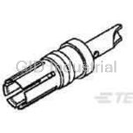
Contact SKT Solder ST Cable Mount 8AWG Bag 0-1393589-7
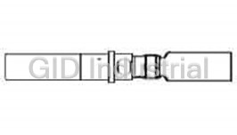
Contact SKT Solder ST Cable Mount 023589-000
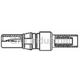
Contact PIN Solder ST Cable Mount Loose 100080-2
Contact SKT Solder ST Cable Mount Loose 100082-1
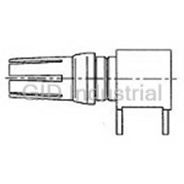
Contact SKT Solder RA Thru-Hole 100092-1
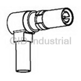
Contact SKT Solder RA Cable Mount Loose 100095-2
Request a Quote

The quote request has been received
Close

Facing challenges or have inquiries? Feel free to contact us!
Call Us +1-469-283-2440
What they say about us
FANTASTIC RESOURCE
One of our top priorities is maintaining our business with precision, and we are constantly looking for affiliates that can help us achieve our goal. With the aid of GID Industrial, our obsolete product management has never been more efficient. They have been a great resource to our company, and have quickly become a go-to supplier on our list!
Bucher Emhart Glass
EXCELLENT SERVICE
With our strict fundamentals and high expectations, we were surprised when we came across GID Industrial and their competitive pricing. When we approached them with our issue, they were incredibly confident in being able to provide us with a seamless solution at the best price for us. GID Industrial quickly understood our needs and provided us with excellent service, as well as fully tested product to ensure what we received would be the right fit for our company.
Fuji
HARD TO FIND A BETTER PROVIDER
Our company provides services to aid in the manufacture of technological products, such as semiconductors and flat panel displays, and often searching for distributors of obsolete product we require can waste time and money. Finding GID Industrial proved to be a great asset to our company, with cost effective solutions and superior knowledge on all of their materials, it’d be hard to find a better provider of obsolete or hard to find products.
Applied Materials
CONSISTENTLY DELIVERS QUALITY SOLUTIONS
Over the years, the equipment used in our company becomes discontinued, but they’re still of great use to us and our customers. Once these products are no longer available through the manufacturer, finding a reliable, quick supplier is a necessity, and luckily for us, GID Industrial has provided the most trustworthy, quality solutions to our obsolete component needs.
Nidec Vamco
TERRIFIC RESOURCE
This company has been a terrific help to us (I work for Trican Well Service) in sourcing the Micron Ram Memory we needed for our Siemens computers. Great service! And great pricing! I know when the product is shipping and when it will arrive, all the way through the ordering process.
Trican Well Service
GO TO SOURCE
When I can't find an obsolete part, I first call GID and they'll come up with my parts every time. Great customer service and follow up as well. Scott emails me from time to time to touch base and see if we're having trouble finding something.....which is often with our 25 yr old equipment.
ConAgra Foods