

 Manufacturers
TE CONNECTIVITY 1055470-1

Description
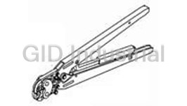
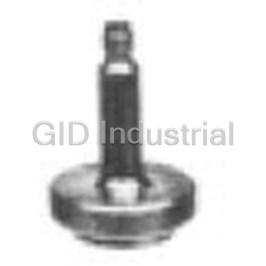
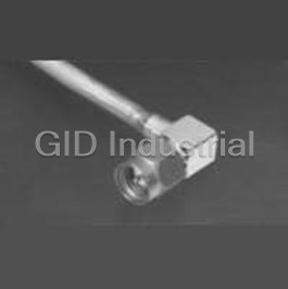
Type N Straight Cable Plug Connector Tools
1055470-1
Part Number
1055470-1
Price
Request Quote
Manufacturer
TE CONNECTIVITY
Lead Time
Request Quote
Category
Tools and Supplies » Assembly Tools
Specifications
Manufacturer
TE Connectivity
Manufacturers Part #
1055470-1
Industry Aliases
1055470-1
Sub-Category
Electronics Assembly Tools
Brand
AMP
Factory Pack Quantity
1
Datasheet
DDEController?Action=showdoc&DocId=Specification+Or+Standard%7F408-8780%7FA%7Fpdf%7FEnglish%7FENG_SS_408-8780_A.pdf
139 KiB

Extracted Text
Instruction Sheet 408-8780 Solder Assembly Kit 1055466-1 11 AUG 11 Rev A ITEM TE PART DESCRIPTION QTY PER KIT NUMBER NUMBER 1 1055439-1 Cable Fixture Sub-Assembly 1 2 1055441-1 Clamp Insert for 02.16 [.085] Cable 1 Set 3 1055547-1 Clamp Insert for 01.78 [.070] Cable 1 Set 4 91362-1 .38 [.015] Thick Solder Gage 1 5 1055460-1 Dielectric Recess Tool 1 6 1055456-1 Locator Tool, Type A 1 7 1055458-1 Dielectric Insert Tool 1 8 1055457-1 Locator Tool, Type A 1 9 1055463-1 Center Contact Holder 1 10 1055459-1 Dielectric Insert Tool 1 11 1055449-1 Locking Ring Pliers 1 12 1055464-1 Locator Tool, Type B 1 13 1055461-1 Locator Tool, Type B 1 Figure 1 Tool directions in this document are for reference 1. INTRODUCTION NOTE only. Refer to the appropriate connector assembly Solder Assembly Kit 1055466-1 for OSSM instructions to insure proper assembly. Refer to i Connectors, shown in Figure 1, contains everything Figure 2 and Figure 3 for connector assemblies necessary to solder OSSM solder-style connectors to and their associated instruction sheets. 2.16 [.085] and 1.78 [.070] diameter semi-rigid and flexible cable. © 2011 Tyco Electronics Corporation, a TE Connectivity Ltd. Company TOOLING ASSISTANCE CENTER 1-800-722-1111 This controlled document is subject to change. 1 of 4 All Rights Reserved PRODUCT INFORMATION 1-800-522-6752 For latest revision and Regional Customer Service, *Trademark visit our website at www.te.com LOC B TE Connectivity, TE connectivity (logo), and TE (logo) are trademarks. Other logos, product and/or Company names may be trademarks of their respective owners. 408-8780 Dimensions are in metric units [with U.S. customary assembly holds and locates coaxial cable for NOTE units in brackets], unless otherwise indicated. soldering. i 3. INSTALLING/REPLACING THE CLAMP INSERT Clamp inserts come in sets of two. Upper and lower NOTE inserts are interchangeable. SEMI-RIGID CABLE CONNECTORS i Connector Part Number Instruction Sheet 1046477-1 408-4776 1. Select the appropriate clamp inserts. Refer to 1046479-1 408-4777 Figure 1 for the appropriate clamp inserts. 1045423-1 1055670-1 408-4792 2. Remove the cable fixture thumbscrew by rotating 1062251-1 1045422-1 it in a counterclockwise direction. 1045401-1 408-4793 3. Remove the positioning tool by rotating it in a 1045381-1 1045410-1 counterclockwise direction. 408-4794 1058589-1 4. Remove the clamp inserts from the frame after 1058588-1 1045351-1 408-4795 the positioning tool is removed. 1045350-1 1062250-1 5. Sandwich the spring in the pockets on the 1045370-1 1045369-1 408-4796 replacement clamp inserts. Figure 2 6. Place clamp inserts in the fixture frame and reinstall the positioning tool. FLEXIBLE CABLE CONNECTORS 7. Retighten positioning tool. Connector Part Number Instruction Sheet 8. Reinstall the thumbscrew. 1045497-1 408-4788 4. TRIMMING CABLE WITH FIXTURE FRAME 1045496-1 408-4789 The fixture frame is equipped with six trimming holes 1062258-1 1045481-1 408-4790 designed to remove the outer jacket and cable 1081231-1 1045482-1 dielectric. The side marked with the number 2 is for 1045477-1 1045476-1 trimming 1.78 [.070], 2.16 [.085], and 3.58 [.141] 408-4791 1062256-1 cable. See Figure 4 and Figure 5. When cable is fully bottomed during trimming, a strip length of 2.79 [.110] 1062257-1 1085817-1 408-4798 will result. If different strip lengths are required the 1045510-1 1045511-1 center conductor must be trimmed separately. 1045507-1 1045508-1 408-4799 The side marked with a number the number "1" is for Figure 3 trimming cable already mounted in a connector housing. See the connector specific instruction sheet Contact customer service or refer to Catalog NOTE for more information. 1308940 for additional information. Trim blades are NOT included with the kit. Use a NOTE i razor blade wih .38 [.015] maximum thickness. i 2. DESCRIPTION Solder Assembly Kit 1055466-1 contains the tooling required to properly solder OSSM connectors to 5. USING SOLDER GAGE AND CENTER CONTACT semi-rigid and flexible coax cable. The kit contains a HOLDER cable fixture sub-assembly, two sets of clamp inserts for 2.16 [.085] and 1.78 [.070] cable, and four types of The center contact holder is designed to hold both locators that are used to properly align the connector male and female center contacts for OSSM and cable. The kit also contains a solder gage for connectors. proper spacing of the center contact, a center contact holder, three dielectric insertion/recess tools, and The solder gage is used to properly space the OSSM locking ring pliers. center contact away from the cable dielectric. The cable fixture subassembly consists of a fixture frame, thumbscrew, positioning tool and spring. See Figure 4. When used with the proper clamp inserts the Rev A 2 of 4 408-8780 Thumb Fixture Frame Screw Positioning Clamp Tool Inserts Cable Trimming Holes Spring Figure 4 To avoid personal injury, be sure to observe all local DANGER safety practices (including the use of gloves). The STOP solder gage, center contact holder, and the contact may be hot after soldering. 6. USING LOCATING TOOLS Solder Assembly Kit 1055466-1 contains four locating For 2.16 tools. Refer to the connector specific instruction sheet [.085] Cable for selection of proper locator tool and assembly instructions. For 3.58 Type A, as well as Type B locating tools are available. [.141] Cable 6.1. Using Type A Locating Tools The solder assembly kit contains two Type A locator tools. These tools are designed to be used with the fixture subassembly. To insure proper connector assembly, follow the instructions listed below. For 1.78 1. Place connector housing on end of cable sub- [.070] Cable assembly. The subassembly refers to cable with center contact. 2. Place loose connector assembly in fixture base. Figure 5 3. Nest the center contact in locator tool. Center contact holders contains small amounts of CAUTION 4. Tighten the thumbscrew to secure the cable. lead. The lead is used for assembly. 5. Tighten the locator tool to seat the cable firmly. ! 6. Slide connector housing over locator tool. 7. Maintain position of housing firmly against locator Maximum operating temperature for the center NOTE tool. contact holder is 300°C [572°F]. i Rev A 3 of 4 408-8780 To avoid personal injury, be sure to follow all local Use the following instruction to press the dielectric DANGER safety practices when using solder and solder bushing into the connector subassembly. equipment. STOP 1. Thread the insertion tool into connector subassembly. 8. Solder according to the connector specific 2. Insert the dielectric into insertion tool housing. instructions. 3. Place insertion tool plunger into position. Fixture should be clamped vertically in vise to keep NOTE 4. Press the plunger until the flange bottoms on the housing seated against locator tool. tool housing. i 8. USING LOCKING RING PLIERS The locking ring pliers are used to compress the 6.2. Using Type B Locating Tools retaining ring, allowing installation of the coupling nut on specific connectors. Use the pliers as follows: The solder assembly kit contains two Type B locator tools. These tools are used to confine the connector 1. Place retaining ring (and gasket) on connector dielectric, which aids in providing proper cable seating housing. when soldering to flexible cable. To insure proper 2. Compress the retaining ring with the retaining connector assembly, follow connector specific ring pliers. instructions. 3. Push coupling nut on to housing and over the 7. USING DIELECTRIC TOOLS retaining ring. Solder Assembly Kit 1055466-1 contains three 4. Check to make sure the coupling nut rotates dielectric tools. Two dielectric (insertion) tools are freely after the retaining ring is in place. used to insert the dielectric bushing into the connector housing. The dielectric (recess) tool is used to 9. REVISION SUMMARY compress expanded cable dielectric after soldering Since the previous release of this document, the new semi-rigid coaxial cable to the connector housing, if company logo was applied. required. Rev A 4 of 4
Frequently asked questions
How does Electronics Finder differ from its competitors?

Is there a warranty for the 1055470-1?
Which carrier will Electronics Finder use to ship my parts?
Can I buy parts from Electronics Finder if I am outside the USA?
Which payment methods does Electronics Finder accept?
Why buy from GID?

Quality
We are industry veterans who take pride in our work

Protection
Avoid the dangers of risky trading in the gray market

Access
Our network of suppliers is ready and at your disposal

Savings
Maintain legacy systems to prevent costly downtime

Speed
Time is of the essence, and we are respectful of yours
Related Products

Torque Wrenches Are Used To Properly Install Or Disassemble The Connectors 1055419-1
Tool For RF Connectors 1055442-1
Tool For RF Connectors 1055443-1
Insertion Tool For RF Connectors 1055447-1
Insertion Tool For RF Connectors 1055448-1
Assembly Tools, Sma Right Angle Cable Plugs 1055451-1
Request a Quote

The quote request has been received
Close

Facing challenges or have inquiries? Feel free to contact us!
Call Us +1-469-283-2440
What they say about us
FANTASTIC RESOURCE
One of our top priorities is maintaining our business with precision, and we are constantly looking for affiliates that can help us achieve our goal. With the aid of GID Industrial, our obsolete product management has never been more efficient. They have been a great resource to our company, and have quickly become a go-to supplier on our list!
Bucher Emhart Glass
EXCELLENT SERVICE
With our strict fundamentals and high expectations, we were surprised when we came across GID Industrial and their competitive pricing. When we approached them with our issue, they were incredibly confident in being able to provide us with a seamless solution at the best price for us. GID Industrial quickly understood our needs and provided us with excellent service, as well as fully tested product to ensure what we received would be the right fit for our company.
Fuji
HARD TO FIND A BETTER PROVIDER
Our company provides services to aid in the manufacture of technological products, such as semiconductors and flat panel displays, and often searching for distributors of obsolete product we require can waste time and money. Finding GID Industrial proved to be a great asset to our company, with cost effective solutions and superior knowledge on all of their materials, it’d be hard to find a better provider of obsolete or hard to find products.
Applied Materials
CONSISTENTLY DELIVERS QUALITY SOLUTIONS
Over the years, the equipment used in our company becomes discontinued, but they’re still of great use to us and our customers. Once these products are no longer available through the manufacturer, finding a reliable, quick supplier is a necessity, and luckily for us, GID Industrial has provided the most trustworthy, quality solutions to our obsolete component needs.
Nidec Vamco
TERRIFIC RESOURCE
This company has been a terrific help to us (I work for Trican Well Service) in sourcing the Micron Ram Memory we needed for our Siemens computers. Great service! And great pricing! I know when the product is shipping and when it will arrive, all the way through the ordering process.
Trican Well Service
GO TO SOURCE
When I can't find an obsolete part, I first call GID and they'll come up with my parts every time. Great customer service and follow up as well. Scott emails me from time to time to touch base and see if we're having trouble finding something.....which is often with our 25 yr old equipment.
ConAgra Foods