

 Manufacturers
TE CONNECTIVITY 10EEJP
Description
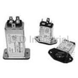
Power Line Filter EMI 50Hz/60Hz 10A 250VAC PC Pins Panel Mount/Through Hole Automotive
10EEJP
Part Number
10EEJP
Price
Request Quote
Manufacturer
TE CONNECTIVITY
Lead Time
Request Quote
Category
Magnetics » Power Line Filter
Specifications
Manufacturer
TE Connectivity
Manufacturers Part #
10EEJP
Industry Aliases
1-6609006-5
Sub-Category
Power Line Filters
Brand
Corcom
Factory Pack Quantity
40
Datasheet
DDEController?Action=srchrtrv&DocNm=1654001_CORCOM_PRODUCT_GUIDE&DocType=CS&DocLang=English&s_cid=1046.pdf
12091 KiB

Extracted Text
Corcom Product Guide Catalog: 1654001 Corcom Product Guide Issue Date: 06.2011 TE Connectivity RFI Power Line Filters Corcom Products TE Connectivity (TE) offers over 300 Engineering Offices solutions for RFI problems associated USA with susceptibility, as well as compliance 620 S. Butterfield Road with international emissions standards. Mundelein, IL 60060 Phone: 847-680-7400 Fax: 847-680-8169 6700 Fallbrook Ave. Suite 287 West Hills, CA 91307 IEC Inlet Filters and Phone: 818-226-4306 Fax: 818-704-1757 Power Entry Modules A complete line of power entry modules Germany solves a variety of power entry needs by Finsinger Feld 1 D-85521 Ottobrunn, combining functions to reduce cost, Phone: 49-89-6089-0 space and labor. Fax: 49-89-6089-767 People’s Republic of China DC Filters 668 Guiping Road Shanghai, 200233 TE has developed a wide range of power Phone: 86-21-2407-1588 Fax: 86-21-2407-1599 line filters and power entry modules that combine several power management For Sales assistance in the functions specifically designed for DC USA please refer to page applications. 286 to find a Corcom prod- uct sales representative in your area. For Sales assis- tance in all other regions, please refer to page 289 to find the Product Informa- Feedthrough Filters and tion Center in your area. Capacitors Designed to offer reliability and performance in high frequency applications and meet EN132200 and 132400 safety requirements. Available for AC or DC applications. Signal Line Products The SignalSentry filtered modular jack connector series combines different levels of filtering with RJ45 and RJ11 modular jacks to address signal line noise problems and crosstalk. Dimensions are in inches and millimeters unless otherwise specified. Values in italics For email, phone or live chat, please go to te.com/help are metric equivalents. Dimensions are shown for reference purposes only. corcom.com Specifications subject to change. Catalog: 1654001 Corcom Product Guide Issue Date: 06.2011 Main Table of Contents Navigating the Catalog . . . . . . . . . . . . . . . . . . . . . . . . . . . . . . . . . . . . . . . . . . . . . . . . . .3 1. RFI Power Line Filters . . . . . . . . . . . . . . . . . . . . . . . . . . . . . . . . . . . . . . . . . . . .9 RFI Power Line Filter Selector Chart . . . . . . . . . . . . . . . . . . . . . . . . . . . . . . . . . . . . . .11 AQ Series . . . . . . . . . . . . . . . . . . . . . . . . . . . . . . . . . . . . . . . . . . . . . . . . . . . . . . . . . . . .12 B Series . . . . . . . . . . . . . . . . . . . . . . . . . . . . . . . . . . . . . . . . . . . . . . . . . . . . . . . . . . . . .15 DK Series . . . . . . . . . . . . . . . . . . . . . . . . . . . . . . . . . . . . . . . . . . . . . . . . . . . . . . . . . . . .18 EBP Series . . . . . . . . . . . . . . . . . . . . . . . . . . . . . . . . . . . . . . . . . . . . . . . . . . . . . . . . . . .21 EDP Series . . . . . . . . . . . . . . . . . . . . . . . . . . . . . . . . . . . . . . . . . . . . . . . . . . . . . . . . . . .21 EOP Series . . . . . . . . . . . . . . . . . . . . . . . . . . . . . . . . . . . . . . . . . . . . . . . . . . . . . . . . . . .21 EMC Series . . . . . . . . . . . . . . . . . . . . . . . . . . . . . . . . . . . . . . . . . . . . . . . . . . . . . . . . . .24 EP & VP Series . . . . . . . . . . . . . . . . . . . . . . . . . . . . . . . . . . . . . . . . . . . . . . . . . . . . . . .27 FC Series . . . . . . . . . . . . . . . . . . . . . . . . . . . . . . . . . . . . . . . . . . . . . . . . . . . . . . . . . . .30 FL Series . . . . . . . . . . . . . . . . . . . . . . . . . . . . . . . . . . . . . . . . . . . . . . . . . . . . . . . . . . . .33 G Series . . . . . . . . . . . . . . . . . . . . . . . . . . . . . . . . . . . . . . . . . . . . . . . . . . . . . . . . . . . . .35 HQ Series . . . . . . . . . . . . . . . . . . . . . . . . . . . . . . . . . . . . . . . . . . . . . . . . . . . . . . . . . . .37 HT Series . . . . . . . . . . . . . . . . . . . . . . . . . . . . . . . . . . . . . . . . . . . . . . . . . . . . . . . . . . .40 HZ Series NEW 4, 6, 10 and 20A versions . . . . . . . . . . . . . . . . . . . . . . . . . . . . . .43 IK Series . . . . . . . . . . . . . . . . . . . . . . . . . . . . . . . . . . . . . . . . . . . . . . . . . . . . . . . . . . . .46 K Series . . . . . . . . . . . . . . . . . . . . . . . . . . . . . . . . . . . . . . . . . . . . . . . . . . . . . . . . . . . . .49 MV Series . . . . . . . . . . . . . . . . . . . . . . . . . . . . . . . . . . . . . . . . . . . . . . . . . . . . . . . . . . .54 N Series . . . . . . . . . . . . . . . . . . . . . . . . . . . . . . . . . . . . . . . . . . . . . . . . . . . . . . . . . . . . .56 Q Series . . . . . . . . . . . . . . . . . . . . . . . . . . . . . . . . . . . . . . . . . . . . . . . . . . . . . . . . . . . . .58 R Series . . . . . . . . . . . . . . . . . . . . . . . . . . . . . . . . . . . . . . . . . . . . . . . . . . . . . . . . . . . . .61 RK Series . . . . . . . . . . . . . . . . . . . . . . . . . . . . . . . . . . . . . . . . . . . . . . . . . . . . . . . . . . .65 S Series . . . . . . . . . . . . . . . . . . . . . . . . . . . . . . . . . . . . . . . . . . . . . . . . . . . . . . . . . . . . .68 SB Series NEW High Performance B Series . . . . . . . . . . . . . . . . . . . . . . . . . . . . .71 SK Series . . . . . . . . . . . . . . . . . . . . . . . . . . . . . . . . . . . . . . . . . . . . . . . . . . . . . . . . . . . .75 T Series . . . . . . . . . . . . . . . . . . . . . . . . . . . . . . . . . . . . . . . . . . . . . . . . . . . . . . . . . . . . .80 U Series . . . . . . . . . . . . . . . . . . . . . . . . . . . . . . . . . . . . . . . . . . . . . . . . . . . . . . . . . . . . .84 V Series . . . . . . . . . . . . . . . . . . . . . . . . . . . . . . . . . . . . . . . . . . . . . . . . . . . . . . . . . . . . .86 W Series . . . . . . . . . . . . . . . . . . . . . . . . . . . . . . . . . . . . . . . . . . . . . . . . . . . . . . . . . . . .86 WG Series . . . . . . . . . . . . . . . . . . . . . . . . . . . . . . . . . . . . . . . . . . . . . . . . . . . . . . . . . . .89 X Series . . . . . . . . . . . . . . . . . . . . . . . . . . . . . . . . . . . . . . . . . . . . . . . . . . . . . . . . . . . . .92 Y Series . . . . . . . . . . . . . . . . . . . . . . . . . . . . . . . . . . . . . . . . . . . . . . . . . . . . . . . . . . . . .92 Z Series . . . . . . . . . . . . . . . . . . . . . . . . . . . . . . . . . . . . . . . . . . . . . . . . . . . . . . . . . . . . .92 2. Three Phase Filters . . . . . . . . . . . . . . . . . . . . . . . . . . . . . . . . . . . . . . . . . . . . .97 Three Phase Selector Chart . . . . . . . . . . . . . . . . . . . . . . . . . . . . . . . . . . . . . . . . . . . . .97 A Series . . . . . . . . . . . . . . . . . . . . . . . . . . . . . . . . . . . . . . . . . . . . . . . . . . . . . . . . . . . . .98 ADT Series . . . . . . . . . . . . . . . . . . . . . . . . . . . . . . . . . . . . . . . . . . . . . . . . . . . . . . . . . .101 AYA Series . . . . . . . . . . . . . . . . . . . . . . . . . . . . . . . . . . . . . . . . . . . . . . . . . . . . . . . . .104 AYC Series . . . . . . . . . . . . . . . . . . . . . . . . . . . . . . . . . . . . . . . . . . . . . . . . . . . . . . . . .108 AYO Series . . . . . . . . . . . . . . . . . . . . . . . . . . . . . . . . . . . . . . . . . . . . . . . . . . . . . . . . . .111 BCF Series NEW Compact Three Phase Filters . . . . . . . . . . . . . . . . . . . . . . . . . .113 CFN Series . . . . . . . . . . . . . . . . . . . . . . . . . . . . . . . . . . . . . . . . . . . . . . . . . . . . . . . . . .116 FCD Series . . . . . . . . . . . . . . . . . . . . . . . . . . . . . . . . . . . . . . . . . . . . . . . . . . . . . . . . . .118 3. Power Inlet Filters & Power Entry Modules . . . . . . . . . . . . . . . . . . . . . . .125 Introduction . . . . . . . . . . . . . . . . . . . . . . . . . . . . . . . . . . . . . . . . . . . . . . . . . . . . . . . . . .126 Selector Chart . . . . . . . . . . . . . . . . . . . . . . . . . . . . . . . . . . . . . . . . . . . . . . . . . . . . . . . .128 Power Entry Module Selector Guide . . . . . . . . . . . . . . . . . . . . . . . . . . . . . . . . . . . . .129 C Series . . . . . . . . . . . . . . . . . . . . . . . . . . . . . . . . . . . . . . . . . . . . . . . . . . . . . . . . . . . .130 CU Series NEW Compact 1U Height Power Entry Module . . . . . . . . . . . . . . . .134 EBF Series . . . . . . . . . . . . . . . . . . . . . . . . . . . . . . . . . . . . . . . . . . . . . . . . . . . . . . . . . .138 EC Series . . . . . . . . . . . . . . . . . . . . . . . . . . . . . . . . . . . . . . . . . . . . . . . . . . . . . . . . . . .141 ED Series . . . . . . . . . . . . . . . . . . . . . . . . . . . . . . . . . . . . . . . . . . . . . . . . . . . . . . . . . . .144 EEA & EEB Series . . . . . . . . . . . . . . . . . . . . . . . . . . . . . . . . . . . . . . . . . . . . . . . . . . .148 EAS & EBS Models . . . . . . . . . . . . . . . . . . . . . . . . . . . . . . . . . . . . . . . . . . . . . . . . .148 EAH & EBH Models . . . . . . . . . . . . . . . . . . . . . . . . . . . . . . . . . . . . . . . . . . . . . . . .148 EEJ Series . . . . . . . . . . . . . . . . . . . . . . . . . . . . . . . . . . . . . . . . . . . . . . . . . . . . . . . . . .153 1 Dimensions are in inches and millimeters unless otherwise specified. Values in italics For email, phone or live chat, please go to te.com/help are metric equivalents. Dimensions are shown for reference purposes only. corcom.com Specifications subject to change. Catalog: 1654001 Corcom Product Guide Issue Date: 06.2011 Table of Contents (continued) EJH & EJHS Models . . . . . . . . . . . . . . . . . . . . . . . . . . . . . . . . . . . . . . . . . . . . . . . .153 EJM & EJMS Models . . . . . . . . . . . . . . . . . . . . . . . . . . . . . . . . . . . . . . . . . . . . . . . .153 EJS Models . . . . . . . . . . . . . . . . . . . . . . . . . . . . . . . . . . . . . . . . . . . . . . . . . . . . . . .153 EF Series . . . . . . . . . . . . . . . . . . . . . . . . . . . . . . . . . . . . . . . . . . . . . . . . . . . . . . . . . . .160 EJT Series . . . . . . . . . . . . . . . . . . . . . . . . . . . . . . . . . . . . . . . . . . . . . . . . . . . . . . . . . .163 GG & HG Series . . . . . . . . . . . . . . . . . . . . . . . . . . . . . . . . . . . . . . . . . . . . . . . . . . . . .166 H Series . . . . . . . . . . . . . . . . . . . . . . . . . . . . . . . . . . . . . . . . . . . . . . . . . . . . . . . . . . . .169 J Series . . . . . . . . . . . . . . . . . . . . . . . . . . . . . . . . . . . . . . . . . . . . . . . . . . . . . . . . . . . . .172 L Series . . . . . . . . . . . . . . . . . . . . . . . . . . . . . . . . . . . . . . . . . . . . . . . . . . . . . . . . . . . .175 LA Series . . . . . . . . . . . . . . . . . . . . . . . . . . . . . . . . . . . . . . . . . . . . . . . . . . . . . . . . . . .180 M Series . . . . . . . . . . . . . . . . . . . . . . . . . . . . . . . . . . . . . . . . . . . . . . . . . . . . . . . . . . . .183 P Series . . . . . . . . . . . . . . . . . . . . . . . . . . . . . . . . . . . . . . . . . . . . . . . . . . . . . . . . . . . .192 SR Series . . . . . . . . . . . . . . . . . . . . . . . . . . . . . . . . . . . . . . . . . . . . . . . . . . . . . . . . . . .201 SRB Series . . . . . . . . . . . . . . . . . . . . . . . . . . . . . . . . . . . . . . . . . . . . . . . . . . . . . . . . .203 4. DC Filters . . . . . . . . . . . . . . . . . . . . . . . . . . . . . . . . . . . . . . . . . . . . . . . . . . . .209 Introduction . . . . . . . . . . . . . . . . . . . . . . . . . . . . . . . . . . . . . . . . . . . . . . . . . . . . . . . . . .210 Selector Chart . . . . . . . . . . . . . . . . . . . . . . . . . . . . . . . . . . . . . . . . . . . . . . . . . . . . . . . . .211 DA Series . . . . . . . . . . . . . . . . . . . . . . . . . . . . . . . . . . . . . . . . . . . . . . . . . . . . . . . . . . .212 DB Series NEW - Compact RFI High Current DC Inlet . . . . . . . . . . . . . . . . . . . .214 DC Series . . . . . . . . . . . . . . . . . . . . . . . . . . . . . . . . . . . . . . . . . . . . . . . . . . . . . . . . . . .217 P Series . . . . . . . . . . . . . . . . . . . . . . . . . . . . . . . . . . . . . . . . . . . . . . . . . . . . . . . . . . . .223 5. Feedthrough Filters and Capacitors . . . . . . . . . . . . . . . . . . . . . . . . . . . . .225 Feedthrough Application Selector Chart . . . . . . . . . . . . . . . . . . . . . . . . . . . . . . . .225 Introduction . . . . . . . . . . . . . . . . . . . . . . . . . . . . . . . . . . . . . . . . . . . . . . . . . . . . . . . . . .226 FFA Series . . . . . . . . . . . . . . . . . . . . . . . . . . . . . . . . . . . . . . . . . . . . . . . . . . . . . . . . .228 FFD Series . . . . . . . . . . . . . . . . . . . . . . . . . . . . . . . . . . . . . . . . . . . . . . . . . . . . . . . . . .231 AFC Series . . . . . . . . . . . . . . . . . . . . . . . . . . . . . . . . . . . . . . . . . . . . . . . . . . . . . . . . .234 DFC Series . . . . . . . . . . . . . . . . . . . . . . . . . . . . . . . . . . . . . . . . . . . . . . . . . . . . . . . . .237 6. Signal Line Products . . . . . . . . . . . . . . . . . . . . . . . . . . . . . . . . . . . . . . . . . . .241 Introduction . . . . . . . . . . . . . . . . . . . . . . . . . . . . . . . . . . . . . . . . . . . . . . . . . . . . . . . . . .242 SignalSentry Filtered Modular Jacks . . . . . . . . . . . . . . . . . . . . . . . . . . . . . . . . . . . .243 SignalSentry Part Number Matrix / Ordering Information . . . . . . . . . . . . . . . . .244 SignalSentry Selector Chart . . . . . . . . . . . . . . . . . . . . . . . . . . . . . . . . . . . . . . . . . . . .245 L Series . . . . . . . . . . . . . . . . . . . . . . . . . . . . . . . . . . . . . . . . . . . . . . . . . . . . . . . . . . . .247 L – Ganged Series . . . . . . . . . . . . . . . . . . . . . . . . . . . . . . . . . . . . . . . . . . . . . . . . . . .248 LC Series . . . . . . . . . . . . . . . . . . . . . . . . . . . . . . . . . . . . . . . . . . . . . . . . . . . . . . . . . . .249 LCT Series . . . . . . . . . . . . . . . . . . . . . . . . . . . . . . . . . . . . . . . . . . . . . . . . . . . . . . . . .250 N Series . . . . . . . . . . . . . . . . . . . . . . . . . . . . . . . . . . . . . . . . . . . . . . . . . . . . . . . . . . . .251 X Series . . . . . . . . . . . . . . . . . . . . . . . . . . . . . . . . . . . . . . . . . . . . . . . . . . . . . . . . . . . .252 Z Series . . . . . . . . . . . . . . . . . . . . . . . . . . . . . . . . . . . . . . . . . . . . . . . . . . . . . . . . . . . .253 Model Dimensions . . . . . . . . . . . . . . . . . . . . . . . . . . . . . . . . . . . . . . . . . . . . . . . . . . . .255 L, LC, LCT and X Series RJ Jack Dimensions . . . . . . . . . . . . . . . . . . . . . . . . . . .255 N and Z Series RJ Jack Dimensions . . . . . . . . . . . . . . . . . . . . . . . . . . . . . . . . . . .257 7. Technical Notes . . . . . . . . . . . . . . . . . . . . . . . . . . . . . . . . . . . . . . . . . . . . . . . .261 Introduction . . . . . . . . . . . . . . . . . . . . . . . . . . . . . . . . . . . . . . . . . . . . . . . . . . . . . . . . . .262 Understanding RFI Power Line Filters . . . . . . . . . . . . . . . . . . . . . . . . . . . . . . . . . . .263 Understanding Hipot Testing . . . . . . . . . . . . . . . . . . . . . . . . . . . . . . . . . . . . . . . . . . .266 Understanding Leakage Current (Touch Current) . . . . . . . . . . . . . . . . . . . . . . . . .267 Understanding Insertion Loss . . . . . . . . . . . . . . . . . . . . . . . . . . . . . . . . . . . . . . . . . .268 Appendix A - Conducted RFI Emissions Testing . . . . . . . . . . . . . . . . . . . . . . . . . .269 Appendix B - Conducted RFI Susceptibility Testing . . . . . . . . . . . . . . . . . . . . . . .270 Appendix C - Health Care Equipment . . . . . . . . . . . . . . . . . . . . . . . . . . . . . . . . . . .270 Appendix D - Safety Agency File Numbers . . . . . . . . . . . . . . . . . . . . . . . . . . . . . . .271 Part Number Index and Cross Reference . . . . . . . . . . . . . . . . . . . . . . . . . . . . . . . . .273 North American Sales Representatives . . . . . . . . . . . . . . . . . . . . . . . . . . . . . . . . . .286 Authorized Corcom Product Distributors . . . . . . . . . . . . . . . . . . . . . . . . . . . . . . . .288 Worldwide Contacts . . . . . . . . . . . . . . . . . . . . . . . . . . . . . . . .Inside Back Cover 2 Dimensions are in inches and millimeters unless otherwise specified. Values in italics For email, phone or live chat, please go to te.com/help are metric equivalents. Dimensions are shown for reference purposes only. corcom.com Specifications subject to change. Catalog: 1654001 Corcom Product Guide Issue Date: 06.2011 Navigating the Catalog Step 1: Determine the product family. The Corcom product guide contains seven sections with six distinct product families. Use the index numbers along the side of the catalog to quickly jump to that section. RFI Power Line Filters Solutions associated with EMI/RFI susceptibility as well as compliance to interna- tional emissions standards for single phase power applications. Includes chassis 1 and board mountable designs as well as single and two-stage filters. Three Phase Filters Solutions associated with EMI/RFI susceptibility as well as compliance to interna- tional emissions standards for three phase and high current applications. 2 IEC Inlet and Power Entry Modules IEC inlet power filters and modular products that address a variety of power entry needs by combining several functions such as on/off switching, voltage selection 3 switching, fuseholder, filtering in combination with the IEC inlet connector. DC Power Line Filters EMI/RFI solutions for emissions and susceptibility specifically related to DC systems often found in central office and telecommunication applications. 4 Feedthrough Filters and Capacitors Products designed for through-bulkhead mounting for high frequency filtering. Designed to meet EN133200 and EN132400 safety requirements. Available in a 5 variety of standard as well as custom configurations. Signal Line Products Products that combine different levels of filtering with various sized RJ modular jacks. Signal line products are used to protect data transmissions as they pass 6 through the RJ jacks or as they are transmitted on the PCB. Technical Notes The appendices in the back of the catalog offer information such as safety agency classifications, general information regarding RFI, and testing procedures. 7 (continued on next page ) Looking for Corcom EMI Facility Products? Power, data and signal line filters for shielded installations Available in Catalog 1654986 - see page 8 for more information 3 Dimensions are in inches and millimeters unless otherwise specified. Values in italics For email, phone or live chat, please go to te.com/help are metric equivalents. Dimensions are shown for reference purposes only. corcom.com Specifications subject to change. Corcom Product Families Catalog: 1654001 Corcom Product Guide Issue Date: 06.2011 Navigating the Catalog (continued) Step 2: Use selector charts For Medical No Application For Attenuate Hardened Selector charts at the beginning of each Coming Out Conducted Equipment Yes of Equipment Yes RFI / EMI Applications section help you to narrow the selection. Try The No AQ Coming Into Series Try The Equipment For 3-6A Switch Page 12 Follow the chart to locate one or several MV Mode Power Series Supply No Yes product series that could fit your specific 3-20A Page 54 application and requirements. HZ For For High Series EN550xxx Class A Noise Industrial 3A (CISPR) Application Page 43 Try The Yes No HT Optimal filter selection requires testing in Series X, Y or Z 6-15A Class B Series Page 40 your specific system, as all systems have 1- 6A Page 92 HQ unique characteristics. Series RK 3-6A Series Page 37 3-20A Try The Try The Page 65 B EBP, EDP,EOP SK Selector charts generally show filters in Series Series Series 1-30A 1-10A 3-40A Page 15 Page 21 Page 75 order of performance from good (at the top) SB B EMC to best performance (at the bottom). Series Series Series 6- 30A 1- 30A 3-30A Page 71 Page 15 Page 24 All Series Try The Try The Are Listed in Ascending EMC K SB Z S Performance Series Series Series Series Series 3-30A 1-60A 6- 30A 1-3A 3-60A from Step 3: Open to the page referenced by the selector chart Page 24 Page 49 Page 71 Page 92 Page 68 FC DK K U V / W Good Series Series Series Series Each product series contains three technical sections. T Series he majority of questions relating 6-50A 1-20A 1-60A 6A 3-20A to Page 30 Page 18 Page 49 Page 84 Page 86 to product applications can be answered directly from these sections. S WG DK N EP / VP Series Series Series Series Series 3-60A 16A 1-20A 6-10A 3-20A Better Page 68 Page 89 Page 18 Page 56 Page 27 to Technical Characteristics: This first section contains pictur V / W EDP - EOPes, appr R opriate saf Q ety agenc G y Series Series Series Series Series 1-20A 3-20A 1-10A 3-20A 6-10A classifications, a description of the series’ capabilities, applications, electrical Page 86 Page 21 Page 61 Page 58 Page 35 specifications, schematics, ordering inf Best ormation and available part numbers. T R EMC FC T Series Series Series Series Series 3-20A 1-20A 3-30A 6-50A 3-20A Page 80 Page 61 Page 24 Page 30 Page 80 Drawings: The second section contains drawings and dimensions of the parts as well as the recommended cutouts. Dimensions are shown in inches with metric equivalents. Performance Data: The third section contains performance data in the form of typical insertion loss graphs and minimum insertion loss tables. If you already know the catalog number or series, the table of contents lists each series in the catalog within each section. The back of the catalog also has an index in alphanumeric order. The index will reference the technical section for that catalog number or series. The index also provides the unique TE ordering number for each part. Step 4: Contact your local Corcom product sales representative Corcom product sales representatives for North America as well as distributors and global contacts are listed in the back of the catalog. Contact the sales representative or office closest to you for technical assistance, stock and pricing. 4 Dimensions are in inches and millimeters unless otherwise specified. Values in italics For email, phone or live chat, please go to te.com/help are metric equivalents. Dimensions are shown for reference purposes only. corcom.com Specifications subject to change. New 60A NEW New Terminations NEW NEW New 60A t n e i c ! E C o Catalog: 1654001 Corcom Product Guide Issue Date: 06.2011 Corcom EMI/RFI Filters and Energy Efficiency The efficiency of an electrical device is the ratio of the power it delivers to the power that it consumes. The difference is wasted as heat, and to prevent over- heating of a device and the system in which it resides, this heat must be transferred out of the system and dissipated. The efficiency of every component, including the power entry module and selected filter, factors into the system’s overall efficiency. When the amount of heat is too great to dissipate through the system’s enclosure, forced air cooling becomes necessary. This is often accom- plished with a fan, and the power used by that fan, (including its own thermal losses) further decreases the system efficiency by another 2% to 5%. Providing room for the fan and air passageways in the equipment increases its size and cost. Careful attention to the efficiency of every component in the system results in a simpler, smaller, lighter, cooler, more competitive product. Corcom EMI filters can help meet energy efficiency goals, including Energy Star rating and the new 80 Plus certification, which now recognizes systems that exceed 90% efficiency. By using the most energy efficient design and materials, Corcom filters can be the beginning of an energy efficient system strategy. Energy efficient power components don’t just lower energy bills and demand for power from the grid, they also increase product reliability. Small efficiency increases can decrease component temperatures throughout the system, and semiconductor life doubles for every 10°C decrease in temperature. Corcom filters are more efficient and run cooler, and this can help reduce system warranty costs, service calls and total support costs. Corcom filters • Have heat dissipation ratings as little as one third that of comparable filters. • Create less heat and run cooler • Improve system reliability • Are more efficient than PC board equivalents • Can help meet system power efficiency standards • Enable systems to be smaller and lighter • Save customers money by reducing energy costs 500 450 400 350 300 250 200 150 100 50 Other Power Entry Modules 0 Corcom CU Series 1A 3A 5 Dimensions are in inches and millimeters unless otherwise specified. Values in italics For email, phone or live chat, please go to te.com/help are metric equivalents. Dimensions are shown for reference purposes only. corcom.com Specifications subject to change. o l e l b a i l e R Heat Dissipation in mW/A Catalog: 1654001 Corcom Product Guide Issue Date: 06.2011 Corcom Products Engineering Services and Custom Solutions Corcom Products Engineering Services and Custom Solutions Corcom Custom Filters TE Connectivity Corcom products were established as the world Key Features: leader in EMI/RFI filtering technology with the introduction of the first line of catalog filter products over 50 years ago. • Custom filter options • Custom wire harness Today, TE continues to pursue the latest in EMI/RFI filter design design by testing and evaluating application specific solutions for a wide • Fully customizeable range of industries. options including packaging In addition to our complete catalog of standard EMI/RFI filtering solutions, TE offers a full range of engineering services and • Agency approvals available as needed by custom products designed for unique applications. customer Corcom custom EMI/RFI product solutions can: • Time and cost savings to customer • Optimize both cost and performance to target a unique • Simplify installation application • Fit unique mechanical size, installation and/or connection Termination and Wiring Customization Options: requirements • Ensure conformance with EMI/RFI requirements of an • Wire length entire system • Wire gauge • Wire color • Apply EMI/RFI filtering in a specific frequency or range • Molded connectors With design and testing facilities worldwide, TE is well suited to • Ring terminals design an EMI/RFI solution that meets a wide range of unique • Custom terminations application needs. To discuss application specific filtering, contact the TE Corcom product sales representative or office closest to you. A complete list of sales representative and worldwide contacts is listed in the back of this catalog. 6 Dimensions are in inches and millimeters unless otherwise specified. Values in italics For email, phone or live chat, please go to te.com/help are metric equivalents. Dimensions are shown for reference purposes only. corcom.com Specifications subject to change. Catalog: 1654001 Corcom Product Guide Issue Date: 06.2011 Corcom Engineering Services and Custom Solutions EMI/RFI Testing Services Corcom Products Test Lab An increase in electronic content and stringent regulatory Key Features: compliance requirements have increased the need for time spent in qualifying test houses. At these “test labs,” products undergo a • We can test product number of qualifying tests which include conducted emissions, to the FCC / EN / EFT EFT, and harmonic content. Failure to comply with associated specifications standards can lead to delayed time-to-market and product • Let us know your redesign resulting in lost revenue and market share and an testing needs and time frame to ensure increase in time spent at the test lab. flexibility of testing TE Connectivity can help by heading off some of the potential and timely results pitfalls during testing and qualifying phases of new products. We offer complimentary testing to existing regulatory standards. Available Testing Standards: We aim for a high standard of accuracy, and can help identify potential problems. • Conducted EMI in We are not a certifying body and our test lab is not a qualified test accordance with FCC lab; however, we test to the same standards and take product part 15 and 18 through the same rigor as any certifying lab. In addition, our • EN55011, EN55022 and EN55014 engineers will recommend a solution and help with a design • EFT (Electrically Fast should a product fail to comply with conducted emissions, EFT Transient) in and/or harmonic content standards. accordance with The advantage is clear: TE will provide you with EN61000-4-4 a high degree of confidence that a product which passed our • Tests conducted up to 30A with insertion loss in-house testing will pass agency testing at a certifying test house measured up to 10GHz in reduced time and with reduced cost. • MIL-STD-461 TE has three Corcom filter testing facilities: CE101 & CE102 • Mundelein, IL, USA (main office and design center) • West Hills, CA, USA (regional office) • Ottobrunn, Germany (regional office and design center) 7 Dimensions are in inches and millimeters unless otherwise specified. Values in italics For email, phone or live chat, please go to te.com/help are metric equivalents. Dimensions are shown for reference purposes only. corcom.com Specifications subject to change. Catalog: 1654001 Corcom Product Guide Issue Date: 06.2011 Corcom EMI / RFI Product Solutions for Facility and Heavy Power Corcom EMI Facility Products Power, data and signal line filters for shielded installations TE Connectivity has dedicated more than 50 years to developing RFI filter technology for electronic devices. We're proud that our focus on the design and production of the highest quality products has made TE a world leader in RFI technology. Our leadership in the filter and power entry module markets was enhanced in 1988 with the aquisition of the Heavy Power Line Division of Cornell Dubilier. The high quality designs and manufacturing of these heavy power line filter products is maintained and enhanced by TE. We have continued that dedication to excellence begun by Cornell Dubilier and inherent to TE’s way of doing business. Only the highest quality designs, capacitors, inductors, and workmanship are used to produce these filters. We recognize the need for great care demanded by hi-rel military filters and automatically apply like quality to the heavy power line products. We treat all product as if it is high-reliability. The Mundelein, IL office provides application engineering service for these heavy power line and military products. Our engineers can help to design a special filter in the rare case a standard product from this catalog cannot adequately solve the problem. Additional product performance data and test results are available from the engineers at this facility. TE’s worldwide sales offices can help you locate information on these products or any of the hundreds of high quality power line filters, power entry modules and SignalSentry products made by TE. For more information on the complete line of EMI Facility products, request catalog number 1654986 or visit www.corcom.com 8 Dimensions are in inches and millimeters unless otherwise specified. Values in italics For email, phone or live chat, please go to te.com/help are metric equivalents. Dimensions are shown for reference purposes only. corcom.com Specifications subject to change. RFI Power Line Filters Catalog: 1654001 Corcom Product Guide Issue Date: 06.2011 1. RFI Power Line Filters — Table of Contents RFI Power Line Filter Selector Chart . . . . . . . . . . . . . . . . . . . . . . . . . . . . . . . . .11 AQ Series . . . . . . . . . . . . . . . . . . . . . . . . . . . . . . . . . . . . . . . . . . . . . . . . . . . . . . . . . . . . . .12 B Series . . . . . . . . . . . . . . . . . . . . . . . . . . . . . . . . . . . . . . . . . . . . . . . . . . . . . . . . . . . . . . .15 DK Series . . . . . . . . . . . . . . . . . . . . . . . . . . . . . . . . . . . . . . . . . . . . . . . . . . . . . . . . . . . . . .18 EBP Series . . . . . . . . . . . . . . . . . . . . . . . . . . . . . . . . . . . . . . . . . . . . . . . . . . . . . . . . . . . . .21 EDP Series . . . . . . . . . . . . . . . . . . . . . . . . . . . . . . . . . . . . . . . . . . . . . . . . . . . . . . . . . . . . .21 EOP Series . . . . . . . . . . . . . . . . . . . . . . . . . . . . . . . . . . . . . . . . . . . . . . . . . . . . . . . . . . . .21 EMC Series . . . . . . . . . . . . . . . . . . . . . . . . . . . . . . . . . . . . . . . . . . . . . . . . . . . . . . . . . . . .24 EP & VP Series . . . . . . . . . . . . . . . . . . . . . . . . . . . . . . . . . . . . . . . . . . . . . . . . . . . . . . . . .27 1 FC Series . . . . . . . . . . . . . . . . . . . . . . . . . . . . . . . . . . . . . . . . . . . . . . . . . . . . . . . . . . . . .30 FL Series . . . . . . . . . . . . . . . . . . . . . . . . . . . . . . . . . . . . . . . . . . . . . . . . . . . . . . . . . . . . . .33 G Series . . . . . . . . . . . . . . . . . . . . . . . . . . . . . . . . . . . . . . . . . . . . . . . . . . . . . . . . . . . . . . .35 HQ Series . . . . . . . . . . . . . . . . . . . . . . . . . . . . . . . . . . . . . . . . . . . . . . . . . . . . . . . . . . . . .37 HT Series . . . . . . . . . . . . . . . . . . . . . . . . . . . . . . . . . . . . . . . . . . . . . . . . . . . . . . . . . . . . .40 HZ Series . . . . . . . . . . . . . . . . . . . . . . . . . . . . . . . . . . . . . . . . . . . . . . . . . . . . . . . . . . . . .43 IK Series . . . . . . . . . . . . . . . . . . . . . . . . . . . . . . . . . . . . . . . . . . . . . . . . . . . . . . . . . . . . . .46 K Series . . . . . . . . . . . . . . . . . . . . . . . . . . . . . . . . . . . . . . . . . . . . . . . . . . . . . . . . . . . . . . .49 MV Series . . . . . . . . . . . . . . . . . . . . . . . . . . . . . . . . . . . . . . . . . . . . . . . . . . . . . . . . . . . . .54 N Series . . . . . . . . . . . . . . . . . . . . . . . . . . . . . . . . . . . . . . . . . . . . . . . . . . . . . . . . . . . . . .56 Q Series . . . . . . . . . . . . . . . . . . . . . . . . . . . . . . . . . . . . . . . . . . . . . . . . . . . . . . . . . . . . . .58 R Series . . . . . . . . . . . . . . . . . . . . . . . . . . . . . . . . . . . . . . . . . . . . . . . . . . . . . . . . . . . . . . .61 RK Series . . . . . . . . . . . . . . . . . . . . . . . . . . . . . . . . . . . . . . . . . . . . . . . . . . . . . . . . . . . . .65 S Series . . . . . . . . . . . . . . . . . . . . . . . . . . . . . . . . . . . . . . . . . . . . . . . . . . . . . . . . . . . . . . .68 SB Series . . . . . . . . . . . . . . . . . . . . . . . . . . . . . . . . . . . . . . . . . . . . . . . . . . . . . . . . . . . . . .71 SK Series . . . . . . . . . . . . . . . . . . . . . . . . . . . . . . . . . . . . . . . . . . . . . . . . . . . . . . . . . . . . . .75 T Series . . . . . . . . . . . . . . . . . . . . . . . . . . . . . . . . . . . . . . . . . . . . . . . . . . . . . . . . . . . . . . .80 U Series . . . . . . . . . . . . . . . . . . . . . . . . . . . . . . . . . . . . . . . . . . . . . . . . . . . . . . . . . . . . . .84 V Series . . . . . . . . . . . . . . . . . . . . . . . . . . . . . . . . . . . . . . . . . . . . . . . . . . . . . . . . . . . . . . .86 W Series . . . . . . . . . . . . . . . . . . . . . . . . . . . . . . . . . . . . . . . . . . . . . . . . . . . . . . . . . . . . . .86 WG Series . . . . . . . . . . . . . . . . . . . . . . . . . . . . . . . . . . . . . . . . . . . . . . . . . . . . . . . . . . . . .89 X Series . . . . . . . . . . . . . . . . . . . . . . . . . . . . . . . . . . . . . . . . . . . . . . . . . . . . . . . . . . . . . . .92 Y Series . . . . . . . . . . . . . . . . . . . . . . . . . . . . . . . . . . . . . . . . . . . . . . . . . . . . . . . . . . . . . . .92 Z Series . . . . . . . . . . . . . . . . . . . . . . . . . . . . . . . . . . . . . . . . . . . . . . . . . . . . . . . . . . . . . . .92 9 Dimensions are in inches and millimeters unless otherwise specified. Values in italics For email, phone or live chat, please go to te.com/help are metric equivalents. Dimensions are shown for reference purposes only. corcom.com Specifications subject to change. Catalog: 1654001 Corcom Product Guide Issue Date: 06.2011 Engineering Notes 10 Dimensions are in inches and millimeters unless otherwise specified. Values in italics For email, phone or live chat, please go to te.com/help are metric equivalents. Dimensions are shown for reference purposes only. corcom.com Specifications subject to change. RFI Power Line Filters Catalog: 1654001 Corcom Product Guide Issue Date: 06.2011 RFI Power Line Filter Selector Chart For Medical No Application For Attenuate Hardened Coming Out Conducted Yes Equipment of Equipment Yes RFI / EMI Applications 1 Try The No AQ Coming Into Series Equipment For Try The 3-6A Switch Page 12 MV Mode Power Series Supply No Yes 3-20A Page 54 HZ For For High Series EN550xxx Class A Noise Industrial 3A (CISPR) Application Page 43 Try The Yes No HT Series X, Y or Z Class B 6-15A Series Page 40 1- 6A Page 92 HQ Series RK 3-6A Series Page 37 3-20A Try The Try The Page 65 B EBP, EDP,EOP SK Series Series Series 1-30A 1-10A 3-40A Page 15 Page 21 Page 75 SB B EMC Series Series Series 6- 30A 1- 30A 3-30A Page 71 Page 15 Page 24 All Series Try The Try The Are Listed in Ascending EMC K SB Z S Performance Series Series Series Series Series 3-30A 1-60A 6- 30A 1-3A 3-60A from Page 49 Page 71 Page 92 Page 68 Page 24 FC DK K U V / W Good Series Series Series Series Series 6-50A 1-20A 1-60A 6A 3-20A to Page 18 Page 49 Page 84 Page 86 Page 30 S WG DK N EP / VP Series Series Series Series Series 3-60A 16A 1-20A 6-10A 3-20A Better Page 18 Page 56 Page 27 Page 68 Page 89 to V / W EDP - EOP R Q G Series Series Series Series Series 3-20A 1-10A 1-20A 3-20A 6-10A Page 61 Page 86 Page 21 Page 58 Page 35 Best T R EMC FC T Series Series Series Series Series 3-20A 1-20A 3-30A 6-50A 3-20A Page 80 Page 61 Page 24 Page 30 Page 80 11 Dimensions are in inches and millimeters unless otherwise specified. Values in italics For email, phone or live chat, please go to te.com/help are metric equivalents. Dimensions are shown for reference purposes only. corcom.com Specifications subject to change. New 60A NEW New Terminations NEW NEW New 60A Catalog: 1654001 Corcom Product Guide Issue Date: 06.2011 High Frequency Power Line Filter or Power Entry Module AQ Series UL Recognized CSA Certified 3VAQ8F 6VAQ8F AQ Series Specifications • Low cost solution to power line noise at high Maximum leakage current each Line to Ground: 3A Models 6A Models frequencies @ 120 VAC 60 Hz: 1.2 mA .7 mA • High common and differential mode performance @250 VAC 50 Hz: 2.3 mA 1.2 mA from 10kHz to 1GHz Hipot rating (one minute): • Available with an IEC inlet, fuseholder and switch Line to Ground: 2250 VDC • Suitable for applications where computers are Line to Line: 1450 VDC used to process secret or confidential information Rated Voltage (max): 250 VAC Operating Frequency: 50/60 Hz Ordering Information Rated Current: 3 or 6A 3 V AQ 8 FS Operating Ambient Temperature Range (at rated current I ): -10°C to +40°C r Suffix In an ambient temperature (T ) higher than +40°C a F – Fuseholder the maximum operating current (I ) is calculated as o FS – Fuseholder & Switch follows: I = I (85-Ta)/45 o r (F & FS on VAQ8 only) Electrical Schematics Omit if none 3A Models Input / Output Style LINE LOAD 3 – Wire leads 8 – IEC inlet* (line side) Wire leads (load side) 6A Models AQ Series LINE LOAD Leakage current designation V – Standard Current Rating 3 or 6A Accessories GA400: NEMA 5-15P to IEC 60320-1 C-13 line cord Available Part Numbers 3VAQ3 6VAQ3 3VAQ8F 6VAQ8F 3VAQ8FS 6VAQ8FS *IEC 60320-1 C14 inlet mates with C13 connector 12 Dimensions are in inches and millimeters unless otherwise specified. Values in italics For email, phone or live chat, please go to te.com/help are metric equivalents. Dimensions are shown for reference purposes only. corcom.com Specifications subject to change. RFI Power Line Filters Catalog: 1654001 Corcom Product Guide Issue Date: 06.2011 High Frequency Power Line Filter or Power Entry Module (continued) AQ Series Case Styles and Dimensions 3VAQ3 6VAQ3 1 1.66 ± .015 2.46 C 2.572 L C L 42.1 ± .38 62.3 65.3 5.126 12.0 Min. 4.14 12.0 Min. 130.0 304.8 105.1 304.8 5.327±.015 (5 places) 4.36 ± .015 135.3 .515 111.4 ± .38 #6-32 .515 13.08 (2 places) #6-32 Thd. 13.08 .5 ± .01 1.0 ± 0.1 #6-32 (2 x) #6-32 12.7 ± .25 25.4 ± .25 3.061 2.0 ± .01 1.98 77.8 50.8 ± .25 40.1 .78 .50 ± .02 12.7 ± .5 19.8 3VAQ8F 6VAQ8F 5.96 6.457 152.0 164 5.68 ± .01 5.06 ± .015 44.3 ± .25 128.6 ± .38 4.0 ± .01 102 ± .25 2.35 ± .015 .90 59.6 ± .38 22.9 2.328 ± .01 3.062 1.125 ± .01 59 ± .35 77.8 2.48 1.58 ±.015 28.6 ± .25 .958 63.0 40 ± .38 24.3 .355 #6-32 .354 ±.010 .391 ± .01 ref ref (6) inserts 9.02 8.99 ± .25 9.93 ± .25 #6-32 .411 ref (6) inserts 12.0 Min. 10.4 12.0 Min. 305.0 305.0 2.576 1.62 65.4 41.2 .375 ± .125 .375 ± .125 9.53 ± 3.2 9.53 ± 3.2 3VAQ8FS 6VAQ8FS 7.125 5.39 ± .015 181.0 .172 136.9 ± .38 1.058 6.347 ± .015 4.37 26.9 2.35 ± .015 161.2 ± .38 #6-32 59.6 ± .38 4.0 ± .015 (6) inserts 101.55 ± .25 .44 11.2 2.48 1.575 ± .015 .958 63.0 2.33 ±.015 40.01 ± .38 3.07 24.3 1.52 ± .01 59.0 ± .38 77.8 38.5 ± .25 #6-32 .411 ref (6) inserts .364 10.4 1.12 ± .01 .391 ± .01 .375 ± .125 9.25 28.3 ± .25 9.93 ± .25 9.53 ± 3.2 12.0 Min. 1.62 304.8 41.2 2.58 65.4 6.30 12.0 Min. .375 ± .125 305.0 160.0 9.53 ± 3.2 13 Dimensions are in inches and millimeters unless otherwise specified. Values in italics For email, phone or live chat, please go to te.com/help are metric equivalents. Dimensions are shown for reference purposes only. corcom.com Specifications subject to change. Catalog: 1654001 Corcom Product Guide Issue Date: 06.2011 High Frequency Power Line Filter or Power Entry Module (continued) AQ Series Recommended Panel Cutouts .910 ± .005 .855 ± .005 23.11 ± .13 .235 ± .005 21.72 ± .13 R 5.969 ± .13 .620 ± .005 15.75 ± .13 1.295 ± .005 32.89 ± .13 .620 ± .005 Dia. 15.75 ± .13 Performance Data Typical Insertion Loss Measured in closed 50 Ohm system 3VAQ 6VAQ db db 100 100 90 90 80 80 70 70 60 60 50 50 40 40 30 30 20 20 10 10 0 0 0.01 0.1 1 10 100 1000 0.01 0.1 1 10 100 1000 Frequency in MHz Frequency in MHz Common Mode / Asymmetrical (L-G) Differential Mode / Symmetrical (L-L) Minimum Insertion Loss Measured in closed 50 Ohm system Common Mode / Asymmetrical (Line to Ground) Differential Mode / Symmetrical (Line to Line) 14 Dimensions are in inches and millimeters unless otherwise specified. Values in italics For email, phone or live chat, please go to te.com/help are metric equivalents. Dimensions are shown for reference purposes only. corcom.com Specifications subject to change. RFI Power Line Filters Catalog: 1654001 Corcom Product Guide Issue Date: 06.2011 General Purpose RFI Filters for High Impedance Loads at Low Current B Series UL Recognized VB6 CSA Certified 1 VDE Approved VB1 / EB1 VB3 / EB3 B Series Specifications • Small size & low cost Maximum leakage current each Line to Ground: VB Models EB Models • General purpose @ 120 VAC 60 Hz: .4 mA .21 mA • Wide variety of termination options @250 VAC 50 Hz: .7 mA .36 mA • Meets low leakage current requirements of VDE Hipot rating (one minute): portable equipment and non-patient medical Line to Ground: 2250 VDC equipment Line to Line: 1450 VDC Rated Voltage (max): 250 VAC Operating Frequency: 50/60 Hz Ordering Information Rated Current: 1 to 30A 10 E B 1 Operating Ambient Temperature Range (at rated current I ): -10°C to +40°C r In an ambient temperature (T ) higher than +40°C Input / Output Style a the maximum operating current (I ) is calculated as 1 – .250 [6.3] spade terminals o follows: I = I (85-Ta)/45 3 – Wire leads o r 6 – Threaded bolt B Series Available Part Numbers Leakage current designation E – Low leakage (<0.5 mA) 1VB1 1EB1 V – Standard 1VB3 1EB3 2VB1 2EB1 Current Rating 2VB3 2EB3 1, 2, 3, 5, 10, 20 or 30A 3VB1 3EB1 3VB3 3EB3 5VB1 5EB1 5VB3 5EB3 Electrical Schematic 10VB1 10EB1 LINE LOAD 10VB3 10EB3 10VB6 20EB1 20VB1 20VB6 30VB6 15 Dimensions are in inches and millimeters unless otherwise specified. Values in italics For email, phone or live chat, please go to te.com/help are metric equivalents. Dimensions are shown for reference purposes only. corcom.com Specifications subject to change. Catalog: 1654001 Corcom Product Guide Issue Date: 06.2011 General Purpose RFI Filters for High Impedance/ Low Current (continued) B Series Case Styles B1 30VB6 E B D E D B 2.00 50.8 A C A C B3 Case Dimensions A B CD E Part No. Blue Blue Green/Yellow 1VB1, 1EB1, E B D 2VB1, 2EB1 Brown Brown 1VB3, 1EB3, 2VB3, 2EB3 3VB1, 3EB1, A C 5VB1, 5EB1 3VB3, 3EB3, 5VB3, 5EB3 10VB1, 10EB1 10VB3, 10EB3 10VB6 & 20VB6 10VB6 20VB1, 20EB1 E DB 20VB6 30VB6 A C 16 Dimensions are in inches and millimeters unless otherwise specified. Values in italics For email, phone or live chat, please go to te.com/help are metric equivalents. Dimensions are shown for reference purposes only. corcom.com Specifications subject to change. RFI Power Line Filters Catalog: 1654001 Corcom Product Guide Issue Date: 06.2011 General Purpose RFI Filters for High Impedance/ Low Current (continued) B Series Common Mode / Asymmetrical (L-G) Performance Data Differential Mode / Symmetrical (L-L) Typical Insertion Loss Measured in closed 50 Ohm system 2EB, 5EB & 10EB 1EB & 3EB 20EB 1 db db db 100 100 100 90 90 90 80 80 80 70 70 70 60 60 60 50 50 50 40 40 40 30 30 30 20 20 20 10 10 10 0 0 0 0.1 1 10 30 0.1 1 10 30 0.1 1 10 30 Frequency in MHz Frequency in MHz Frequency in MHz 1VB 2VB 3VB db db db 100 100 100 90 90 90 80 80 80 70 70 70 60 60 60 50 50 50 40 40 40 30 30 30 20 20 20 10 10 10 0 0 0 0.1 1 10 30 0.1 1 10 30 0.1 1 10 30 Frequency in MHz Frequency in MHz Frequency in MHz 10VB 20VB 30VB db db db 100 100 100 90 90 90 80 80 80 70 70 70 60 60 60 50 50 50 40 40 40 30 30 30 20 20 20 10 10 10 0 0 0 0.1 1 10 30 0.1 1 10 30 0.1 1 10 30 Frequency in MHz Frequency in MHz Frequency in MHz Minimum Insertion Loss Measured in closed 50 Ohm system Common Mode / Asymmetrical (Line to Ground) 17 Dimensions are in inches and millimeters unless otherwise specified. Values in italics For email, phone or live chat, please go to te.com/help are metric equivalents. Dimensions are shown for reference purposes only. corcom.com Specifications subject to change. Catalog: 1654001 Corcom Product Guide Issue Date: 06.2011 Enhanced Differential Mode Performance K Series RFI Line Filters DK Series DK3 UL Recognized CSA Certified VDE Approved DK1 DK6 DK Series Specifications • Higher performance Line to Line attenuation than Maximum leakage current each Line to Ground: VDK Models EDK Models the K Series @ 120 VAC 60 Hz: .4 mA .22 mA • E version meets the low leakage current @250 VAC 50 Hz: .7 mA .38 mA requirements of VDE portable equipment Hipot rating (one minute): and non-patient care equipment Line to Ground: 2250 VDC • V version features same high performance Line to Line: 1450 VDC with more cost-effective design Rated Voltage (max): 250 VAC Operating Frequency: 50/60 Hz Ordering Information Rated Current: 1 to 20A 10 E DK 3 Operating Ambient Temperature Range (at rated current I ): -10°C to +40°C r In an ambient temperature (T ) higher than +40°C Input / Output Style a the maximum operating current (I ) is calculated as 1 – .250 [6.3] spade terminals o follows: I = I (85-Ta)/45 3 – Wire leads o r 6 – Threaded bolt DK Series Available Part Numbers Leakage current designation E – Low leakage (<0.5 mA) 1VDK1 1EDK1 V – Standard 1VDK3 1EDK3 3VDK1 3EDK1 Current Rating 3VDK3 3EDK3 1, 3, 6, 10, or 20A 6VDK1 6EDK1 6VDK3 6EDK3 10VDK1 10EDK1 Electrical Schematic 10VDK3 10EDK3 20VDK1 20EDK1 LINE LOAD 20VDK6 18 Dimensions are in inches and millimeters unless otherwise specified. Values in italics For email, phone or live chat, please go to te.com/help are metric equivalents. Dimensions are shown for reference purposes only. corcom.com Specifications subject to change. RFI Power Line Filters Catalog: 1654001 Corcom Product Guide Issue Date: 06.2011 Enhanced Differential Mode K Series RFI Power Line Filters (continued) DK Series Case Styles VDK1 / EDK1 20VDK6 1 E C D ED B B A A C VDK3 / EDK3 E C Case Dimensions D A B CD E Blue Part No. Blue B Brown Brown 1VDK1, 1EDK1 1VDK3, 1EDK3 Green/ A Yellow 3VDK1, 3EDK1, 6VDK1, 6EDK1 3VDK3, 3EDK3, 6VDK3, 6EDK3 10VDK1, 20VDK1 / 20EDK1 10EDK1 10VDK3, 10EDK3 20VDK1, 20EDK1 ED B 20VDK6 C A 19 Dimensions are in inches and millimeters unless otherwise specified. Values in italics For email, phone or live chat, please go to te.com/help are metric equivalents. Dimensions are shown for reference purposes only. corcom.com Specifications subject to change. Catalog: 1654001 Corcom Product Guide Issue Date: 06.2011 Enhanced Differential Mode K Series RFI Power Line Filters (continued) DK Series Performance Data Typical Insertion Loss Measured in closed 50 Ohm system 1 & 3VDK 6, 10, 20VDK 1 & 3EDK 6, 10, 20EDK db db db db 100 100 100 100 90 90 90 90 80 80 80 80 70 70 70 70 60 60 60 60 50 50 50 50 40 40 40 40 30 30 30 30 20 20 20 20 10 10 10 10 0 0 0 0 0.1 1 10 30 0.1 1 10 30 0.1 1 10 30 0.1 1 10 30 Frequency in MHz Frequency in MHz Frequency in MHz Frequency in MHz Common Mode / Asymmetrical (L-G) Differential Mode / Symmetrical (L-L) Minimum Insertion Loss Measured in closed 50 Ohm system Common Mode / Asymmetrical (Line to Ground) Differential Mode / Symmetrical (Line to Line) 20 Dimensions are in inches and millimeters unless otherwise specified. Values in italics For email, phone or live chat, please go to te.com/help are metric equivalents. Dimensions are shown for reference purposes only. corcom.com Specifications subject to change. RFI Power Line Filters Catalog: 1654001 Corcom Product Guide Issue Date: 06.2011 PC Board Mountable General Purpose RFI Filters EBP, EDP & EOP Series UL Recognized* CSA Certified* 1 1EDP / 1EOP VDE Approved* 1EBP EBP Series Specifications • General purpose Maximum leakage current each Line to Ground: EDP/EOP EBP • Low leakage current @ 120 VAC 60 Hz: .22 mA .13 mA • Cost-effective @250 VAC 50 Hz: .38 mA .21 mA • Compact size Hipot rating (one minute): Line to Ground: 2250 VDC Line to Line: 1450 VDC EDP Series Rated Voltage (max): 250 VAC • Enhanced differential mode performance Operating Frequency: 50/60 Hz • Low leakage current • Cost-effective Rated Current: 1 to 10A Operating Ambient Temperature Range (at rated current I ): -10°C to +40°C r EOP Series In an ambient temperature (T ) higher than +40°C a • General purpose the maximum operating current (I ) is calculated as o follows: I = I (85-Ta)/45 • Low leakage current o r • Cost-effective Electrical Schematic EBP Ordering Information LINE LOAD 6 EDP EBP Series Compact Size EDP & EOP EDP Series LINE LOAD Enhanced Performance EOP Series General Performance Current Rating Available Part Numbers 1, 3, 6 or 10A 1EBP 3EBP 1EDP 1EOP 3EDP 3EOP 6EDP 6EOP *EBP models are approved to VDE standards only 10EDP 10EOP 21 Dimensions are in inches and millimeters unless otherwise specified. Values in italics For email, phone or live chat, please go to te.com/help are metric equivalents. Dimensions are shown for reference purposes only. corcom.com Specifications subject to change. Catalog: 1654001 Corcom Product Guide Issue Date: 06.2011 PC Board Mountable General Purpose RFI Filters (continued) EBP, EDP, EOP Series Case Styles Case Dimensions EBP A AB C Part No. EBP C EDP EOP .35 Max. 8.97 LINE .787 20.00 B .394 10.00 LOAD .098 .590 .098 2.5 15.0 2.5 Performance Data EDP / EOP Typical Insertion Loss A Measured in closed 50 Ohm system C 1EBP 3EBP .35 db db Max. 100 100 8.97 90 90 80 80 70 70 60 60 50 50 .31 ± .02 LINE LOAD 40 40 7.87 ± .5 30 30 20 20 .591 ± .006 10 10 B 15.00 ± .15 0 0 0.1 1 10 30 0.1 1 10 30 Frequency in MHz Frequency in MHz .295 ± .006 7.50 ± .15 .689 ± .006 17.50 ± .15 .36 ± .02 Common Mode / Asymmetrical (L-G) 9.10 ± .5 Differential Mode / Symmetrical (L-L) 22 Dimensions are in inches and millimeters unless otherwise specified. Values in italics For email, phone or live chat, please go to te.com/help are metric equivalents. Dimensions are shown for reference purposes only. corcom.com Specifications subject to change. RFI Power Line Filters Catalog: 1654001 Corcom Product Guide Issue Date: 06.2011 PC Board Mountable General Purpose RFI Filters (continued) EBP, EDP & EOP Series Performance Data (continued) Typical Insertion Loss Common Mode / Asymmetrical (L-G) Differential Mode / Symmetrical (L-L) Measured in closed 50 Ohm system 1 1EDP 3EDP 6EDP 10EDP db db db db 100 100 100 100 90 90 90 90 80 80 80 80 70 70 70 70 60 60 60 60 50 50 50 50 40 40 40 40 30 30 30 30 20 20 20 20 10 10 10 10 0 0 0 0 0.1 1 10 30 0.1 1 10 30 0.1 1 10 30 0.1 1 10 30 Frequency in MHz Frequency in MHz Frequency in MHz Frequency in MHz 1EOP 3EOP 6EOP 10EOP db db db db 100 100 100 100 90 90 90 90 80 80 80 80 70 70 70 70 60 60 60 60 50 50 50 50 40 40 40 40 30 30 30 30 20 20 20 20 10 10 10 10 0 0 0 0 0.1 1 10 30 0.1 1 10 30 0.1 1 10 30 0.1 1 10 30 Frequency in MHz Frequency in MHz Frequency in MHz Frequency in MHz Minimum Insertion Loss Measured in closed 50 Ohm system Common Mode / Asymmetrical (Line to Ground) Differential Mode / Symmetrical (Line to Line) 23 Dimensions are in inches and millimeters unless otherwise specified. Values in italics For email, phone or live chat, please go to te.com/help are metric equivalents. Dimensions are shown for reference purposes only. corcom.com Specifications subject to change. Catalog: 1654001 Corcom Product Guide Issue Date: 06.2011 Compact and Cost-effective Dual Stage RFI Power Line Filters EMC Series UL Recognized CSA Certified VDE Approved EMC6 EMC1 EMC Series Specifications Maximum leakage current each Line to Ground: • Compact dual stage filter series 3, 6, 10A 15, 20, 30A • Cost-effective design @ 120 VAC 60 Hz: .21 mA .73 mA @250 VAC 50 Hz: .43 mA 1.52 mA • Current rating up to 30A Hipot rating (one minute): • High differential mode attenuation in the Line to Ground: 2250 VDC Line to Line: 1450 VDC lower frequency range Rated Voltage (max): 250 VAC • High common mode performance Operating Frequency: 50/60 Hz • Suitable for switching mode power supplies Rated Current: 3 to 30A Operating Ambient Temperature Range (at rated current I ): -10°C to +40°C r In an ambient temperature (T ) higher than +40°C a the maximum operating current (I ) is calculated as o follows: I = I (85-Ta)/45 o r Ordering Information Electrical Schematic 10 EMC 1 LINE LOAD Case Styles 1 – .250 [6.3] spade terminals 3 – Wire leads 6 – Threaded bolt EMC Series Available Part Numbers Current Rating 3, 6, 10, 15, 20 or 30A 3EMC1 10EMC3 6EMC1 15EMC3 10EMC1 10EMC6 15EMC1 15EMC6 20EMC1 20EMC6 3EMC3 30EMC6 6EMC3 24 Dimensions are in inches and millimeters unless otherwise specified. Values in italics For email, phone or live chat, please go to te.com/help are metric equivalents. Dimensions are shown for reference purposes only. corcom.com Specifications subject to change. RFI Power Line Filters Catalog: 1654001 Corcom Product Guide Issue Date: 06.2011 Compact and Cost-effective Dual Stage RFI Power Line Filters (continued) EMC Series Case Styles EMC1 30EMC6 1 B E D B C D E A C A Case Dimensions EMC3 A B CD E Part No. Green/ Yellow 3EMC1 Brown Brown B 6EMC1 Blue Blue 10EMC1 A D C 15EMC1 E 20EMC1 3EMC3 6EMC3 EMC6 10EMC3 15EMC3 B 10EMC6 15EMC6 20EMC6 D C 30EMC6 E A 25 Dimensions are in inches and millimeters unless otherwise specified. Values in italics For email, phone or live chat, please go to te.com/help are metric equivalents. Dimensions are shown for reference purposes only. corcom.com Specifications subject to change. Catalog: 1654001 Corcom Product Guide Issue Date: 06.2011 Compact and Cost-effective Dual Stage RFI Power Line Filters (continued) EMC Series Performance Data Typical Insertion Loss Measured in closed 50 Ohm system 3EMC 6EMC 10EMC 15EMC db db db db 100 100 100 100 90 90 90 90 80 80 80 80 70 70 70 70 60 60 60 60 50 50 50 50 40 40 40 40 30 30 30 30 20 20 20 20 10 10 10 10 0 0 0 0 0.1 1 10 30 0.1 1 10 30 0.1 1 10 30 0.1 1 10 30 Frequency in MHz Frequency in MHz Frequency in MHz Frequency in MHz 20EMC 30EMC db db 100 100 90 90 80 80 Common Mode / Asymmetrical (L-G) 70 70 60 60 Differential Mode / Symmetrical (L-L) 50 50 40 40 30 30 20 20 10 10 0 0 0.1 1 10 30 0.1 1 10 30 Frequency in MHz Frequency in MHz Minimum Insertion Loss Common Mode / Asymmetrical (Line to Ground) Differential Mode / Symmetrical (Line to Line) 26 Dimensions are in inches and millimeters unless otherwise specified. Values in italics For email, phone or live chat, please go to te.com/help are metric equivalents. Dimensions are shown for reference purposes only. corcom.com Specifications subject to change. RFI Power Line Filters Catalog: 1654001 Corcom Product Guide Issue Date: 06.2011 Dual Stage RFI Power Line Filters for Switching Mode Power Supplies EP / VP Series UL Recognized EP7 / VP7 CSA Certified 1 VDE Approved EP1 / VP1 EP3 / VP3 EP & VP Series Specifications • Dual stage filter offers high insertion loss Maximum leakage current each Line to Ground: VP Models EP Models • Well suited for meeting CISPR 22 A and @ 120 VAC 60 Hz: .73 mA .21 mA FCC Part 15J, Class B @250 VAC 50 Hz: 1.27 mA .36 mA • EP model meets very low leakage current Hipot rating (one minute): requirements Line to Ground: 2250 VDC • 7A and 12A versions offer optimum package size Line to Line: 1450 VDC Rated Voltage (max): 250 VAC Ordering Information Operating Frequency: 50/60 Hz Rated Current: 3 to 20A 3 EP 7 M Operating Ambient Temperature Range (at rated current I ): -10°C to +40°C Suffix r In an ambient temperature (T ) higher than +40°C M – Metric inserts (style 7 only) a the maximum operating current (I ) is calculated as Omit for standard or none o follows: I = I (85-Ta)/45 o r Input / Output Style 1 – .250 [6.3] spade terminals 3 – Wire leads Available Part Numbers 6 – Threaded bolt 3EP1 10EP1 7 – IEC inlet* (line side) 3EP3 10EP3 .250 [6.3] spade terminals 3EP7 12EP1 (load side) 3EP7M 12EP3 6EP1 20EP1 EP / VP Series 6EP3 20EP6 EP – Low leakage (<0.5 mA) 7EP1 20VP1 VP – Standard (20A only) 7EP3 20VP6 Current Rating 3, 6, 7, 10, 12 or 20A Accessories GA400: NEMA 5-15P to IEC 60320-1 C-13 line cord Electrical Schematic LINE LOAD *IEC 60320-1 C14 inlet mates with C13 connector 27 Dimensions are in inches and millimeters unless otherwise specified. Values in italics For email, phone or live chat, please go to te.com/help are metric equivalents. Dimensions are shown for reference purposes only. corcom.com Specifications subject to change. Catalog: 1654001 Corcom Product Guide Issue Date: 06.2011 Dual Stage RFI Filters for Switching Power Supplies (continued) EP / VP Series Case Styles EP1 / VP1 (1-15A) EP7 & EP7M Tapped insert B B D D E A E A C C 20EP1 / VP1 20EP6 / VP6 B B D D E E C A A C EP3 Recommended Panel Cutout .235 R .157 E 5.96 Dia. (2) C 3.98 D Brown .910 Brown 23.11 B Blue Blue 1.295 32.89 1.575 Green/ A 40.01 Yellow 28 Dimensions are in inches and millimeters unless otherwise specified. Values in italics For email, phone or live chat, please go to te.com/help are metric equivalents. Dimensions are shown for reference purposes only. corcom.com Specifications subject to change. RFI Power Line Filters Catalog: 1654001 Corcom Product Guide Issue Date: 06.2011 Dual Stage RFI Filters for Switching Power Supplies (continued) EP / VP Series Case Dimensions Typical Insertion Loss (continued) A B CD E 12EP 20EP Part No. db db 100 100 90 90 80 80 3EP1 70 70 1 60 60 50 3EP3 50 40 40 30 30 3EP7/7M 20 20 10 10 0 0 0.01 0.1 1 10 30 0.01 0.1 1 10 30 6EP1 Frequency in MHz Frequency in MHz 20VP db 6EP3 100 90 80 Common Mode / 7EP1 70 Asymmetrical (L-G) 60 Differential Mode / 50 7EP3 Symmetrical (L-L) 40 30 20 10EP1 10 0 0.01 0.1 1 10 30 10EP3 Frequency in MHz Minimum Insertion Loss 12EP1 Measured in closed 50 Ohm system 12EP3 Common Mode / Asymmetrical (Line to Ground) 20EP1/VP1 20EP6/VP6 Performance Data Typical Insertion Loss Measured in closed 50 Ohm system 3EP 6EP db db 100 100 90 90 80 80 70 70 60 60 Differential Mode / Symmetrical (Line to Line) 50 50 40 40 30 30 20 20 10 10 0 0 0.01 0.1 1 10 30 0.01 0.1 1 10 30 Frequency in MHz Frequency in MHz 7EP 10EP db db 100 100 90 90 80 80 70 70 60 60 50 50 40 40 30 30 20 20 10 10 0 0 0.01 0.1 1 10 30 0.01 0.1 1 10 30 Frequency in MHz Frequency in MHz 29 Dimensions are in inches and millimeters unless otherwise specified. Values in italics For email, phone or live chat, please go to te.com/help are metric equivalents. Dimensions are shown for reference purposes only. corcom.com Specifications subject to change. Catalog: 1654001 Corcom Product Guide Issue Date: 06.2011 Single Phase Power Line Filter for Frequency Converters FC Series UL Recognized FC Series Specifications • Designed for frequency inverters and variable Maximum leakage current each Line to Ground: B suffix no suffix speed motor drives @ 120 VAC 60 Hz: 3.9 mA 3.8 mA • Suitable for electronically noisy environments @250 VAC 50 Hz: 7.0 mA 6.7 mA • Protects programmable logic controllers from RF Hipot rating (one minute): noise on the AC power line Line to Ground: 2250 VDC • Side flanges for easy mounting Line to Line: 1450 VDC • Touch safe terminals provide easy connections Rated Voltage (max): 250 VAC and prevent inadvertent contact for safety in the Operating Frequency: 50/60 Hz most demanding applications Rated Current: 6 to 50A Operating Ambient Temperature Range (at rated current I ): -10°C to +40°C r Ordering Information In an ambient temperature (T ) higher than +40°C a the maximum operating current (I ) is calculated as o 36 FC 10 B follows: I = I (85-Ta)/45 o r Suffix Electrical Schematics B – Single stage Omit for dual stage FC10 LINE LOAD Input / Output Style 10 – DIN type terminal block 1 2 FC Series 1 Current Rating 6, 12, 16, 25, 36 or 50A FC10B Available Part Numbers 6FC10 LINE LOAD 12FC10 12FC10B 16FC10 16FC10B 25FC10 25FC10B 36FC10 36FC10B 50FC10 50FC10B 30 Dimensions are in inches and millimeters unless otherwise specified. Values in italics For email, phone or live chat, please go to te.com/help are metric equivalents. Dimensions are shown for reference purposes only. corcom.com Specifications subject to change. RFI Power Line Filters Catalog: 1654001 Corcom Product Guide Issue Date: 06.2011 Single Phase Filter for Frequency Converters (continued) FC Series Case Styles Case Dimensions A B CD E F Part No. FC10 / FC10B (6, 12, 16A) 6FC10 1 12FC10/10B D 16FC10/10B B 25, 36, 50 FC10/10B C F E This hole indicates A the "Line" side and may be on either flange. FC10 / FC10B (25, 36, 50A ) This hole indicates the "Line" side and may be on either flange. D B C F E A 31 Dimensions are in inches and millimeters unless otherwise specified. Values in italics For email, phone or live chat, please go to te.com/help are metric equivalents. Dimensions are shown for reference purposes only. corcom.com Specifications subject to change. Catalog: 1654001 Corcom Product Guide Issue Date: 06.2011 Single Phase Filter for Frequency Converters (continued) FC Series Performance Data Common Mode / Asymmetrical (L-G) Typical Insertion Loss Differential Mode / Symmetrical (L-L) Measured in closed 50 Ohm system 6FC10 12FC10 16FC10 db db db 100 100 100 90 90 90 80 80 80 70 70 70 60 60 60 50 50 50 40 40 40 30 30 30 20 20 20 10 10 10 0 0 0 0.01 0.1 1 10 30 0.01 0.1 1 10 30 0.01 0.1 1 10 30 Frequency in MHz Frequency in MHz Frequency in MHz 25FC10 36, 50FC10 12, 16FC10B db db db 100 100 100 90 90 90 80 80 80 70 70 70 60 60 60 50 50 50 40 40 40 30 30 30 20 20 20 10 10 10 0 0 0 0.01 0.1 1 10 30 0.01 0.1 1 10 30 0.01 0.1 1 10 30 Frequency in MHz Frequency in MHz Frequency in MHz 25FC10B 36FC10B 50FC10B db db db 100 100 100 90 90 90 80 80 80 70 70 70 60 60 60 50 50 50 40 40 40 30 30 30 20 20 20 10 10 10 0 0 0 0.01 0.1 1 10 30 0.01 0.1 1 10 30 0.01 0.1 1 10 30 Frequency in MHz Frequency in MHz Frequency in MHz Minimum Insertion Loss Common Mode / Asymmetrical (Line to Ground) Differential Mode / Symmetrical (Line to Line) 32 Dimensions are in inches and millimeters unless otherwise specified. Values in italics For email, phone or live chat, please go to te.com/help are metric equivalents. Dimensions are shown for reference purposes only. corcom.com Specifications subject to change. RFI Power Line Filters Catalog: 1654001 Corcom Product Guide Issue Date: 06.2011 Differential Mode Filter for Fluorescent Lighting Applications FL Series UL Listed 1 FL Series Specifications • Specifically designed for fluorescent lights Maximum leakage current each Line to Ground: @ 125 VAC 60 Hz: 3.0 mA • Suitable for industrial environments @280 VAC 50 Hz: 6.0 mA • UL Listed for aftermarket installation Hipot rating (one minute): Line to Ground: 1560 VAC Line to Line: 1560 VAC Rated Voltage: 125/280 VAC Operating Frequency: 50/60 Hz Rated Current: 3.9 A Operating Ambient Temperature Range (at rated current I ): -10°C to +40°C r In an ambient temperature (T ) higher than +40°C a Ordering Information the maximum operating current (I ) is calculated as o follows: I = I (85-Ta)/45 3 FL 3 o r Input / Output Style Electrical Schematic 3 – Wire leads FL Series LOAD LINE Current Rating 3 – 3.9A Available Part Number 3FL3 33 Dimensions are in inches and millimeters unless otherwise specified. Values in italics For email, phone or live chat, please go to te.com/help are metric equivalents. Dimensions are shown for reference purposes only. corcom.com Specifications subject to change. Catalog: 1654001 Corcom Product Guide Issue Date: 06.2011 Differential Mode Filter for Fluorescent Lighting Applications (continued) FL Series Case Styles Case Dimensions A B CD E Part No. C D 3FL3 0.44 11.18 B 0.44 7.0 E 177.8 Min. (4 Wires) Strip 0.50 12.7 (Typ) A 18 AWG (4X) Performance Data Typical Insertion Loss Measured in closed 50 Ohm system 3FL3 db 100 90 80 70 60 Differential Mode / Symmetrical (L-L) 50 40 30 20 10 0 0.1 1 10 30 Frequency in MHz Minimum Insertion Loss Differential Mode / Symmetrical (Line to Line) 34 Dimensions are in inches and millimeters unless otherwise specified. Values in italics For email, phone or live chat, please go to te.com/help are metric equivalents. Dimensions are shown for reference purposes only. corcom.com Specifications subject to change. Line Load RFI Power Line Filters Catalog: 1654001 Corcom Product Guide Issue Date: 06.2011 High Performance RFI Filters for Switching Power Supplies G Series UL Recognized CSA Certified 1 VDE Approved 10EG1 / 10VG1 6EG1 / 6VG1 G Series Specifications • Designed to provide excellent attenuation for Maximum leakage current each Line to Ground: EG Models VG Models most digital electronics equipment @ 120 VAC 60 Hz: .30 mA 1.2 mA • Broad frequency range of performance from @250 VAC 50 Hz: .50 mA 2.0 mA 20kHz to 30MHz Hipot rating (one minute): • Size and cost-effective solution Line to Ground: 2250 VDC • Designed to help comply with EN55022 Level A Line to Line: 1450 VDC and FCC Part 15J Class B Rated Voltage (max): 250 VAC Operating Frequency: 50/60 Hz Rated Current: 6 & 10A Ordering Information Operating Ambient Temperature Range (at rated current I ): -10°C to +40°C r 10 E G 1 In an ambient temperature (T ) higher than +40°C a the maximum operating current (I ) is calculated as o Input / Output Style follows: I = I (85-Ta)/45 o r 1 – .250 [6.3] spade terminals Electrical Schematics G Series Leakage current designation 6EG1 & 6VG1 E – Low leakage (<0.5 mA) LINE LOAD V – Standard Current Rating 6 or 10A Available Part Numbers 10EG1 & 10VG1 6EG1 6VG1 LINE LOAD 10EG1 10VG1 35 Dimensions are in inches and millimeters unless otherwise specified. Values in italics For email, phone or live chat, please go to te.com/help are metric equivalents. Dimensions are shown for reference purposes only. corcom.com Specifications subject to change. Catalog: 1654001 Corcom Product Guide Issue Date: 06.2011 High Performance RFI Filters for Switching Power Supplies (continued) G Series Case Styles Case Dimensions A B CD E Part No. 6EG1/VG1 B 10EG1/VG1 D C E A Performance Data Common Mode / Asymmetrical (L-G) Typical Insertion Loss Differential Mode / Symmetrical (L-L) Measured in closed 50 Ohm system 6EG1 6VG1 10EG1 10VG1 db db db db 100 100 100 100 90 90 90 90 80 80 80 80 70 70 70 70 60 60 60 60 50 50 50 50 40 40 40 40 30 30 30 30 20 20 20 20 10 10 10 10 0 0 0 0 0.01 0.1 1 10 30 0.01 0.1 1 10 30 0.01 0.1 1 10 30 0.01 0.1 1 10 30 Frequency in MHz Frequency in MHz Frequency in MHz Frequency in MHz Minimum Insertion Loss Common Mode / Asymmetrical (Line to Ground) Differential Mode / Symmetrical (Line to Line) 36 Dimensions are in inches and millimeters unless otherwise specified. Values in italics For email, phone or live chat, please go to te.com/help are metric equivalents. Dimensions are shown for reference purposes only. corcom.com Specifications subject to change. RFI Power Line Filters Catalog: 1654001 Corcom Product Guide Issue Date: 06.2011 Highest Performance RFI Filters for Medical Equipment HQ Series 3EHQ3 UL Recognized 6EHQ8 CSA Certified 1 VDE Approved 3EHQ1 HQ Series Specifications • Designed to provide the highest available Maximum leakage current each Line to Ground: @ 120 VAC 60 Hz: 2 A attenuation of RFI noise in the frequency range @250 VAC 50 Hz: 5 A from 10kHz to 30MHz for low leakage current applications Hipot rating (one minute): • Size and cost-effective Line to Ground: 2250 VDC Line to Line: 1450 VDC Rated Voltage (max): 250 VAC Operating Frequency: 50/60 Hz Rated Current: 3 & 6A Operating Ambient Temperature Range (at rated current I ): -10°C to +40°C r In an ambient temperature (T ) higher than +40°C a the maximum operating current (I ) is calculated as o follows: I = I (85-Ta)/45 o r Ordering Information 6 E HQ 8 M Available Part Numbers Suffix M – Metric inserts (style 8 only) 3EHQ1 6EHQ1 Omit for standard or none 3EHQ3 6EHQ3 3EHQ8 6EHQ8 Input / Output Style 3EHQ8M 3EHQ8M 1 – .250 [6.3] spade terminals 3 – Wire leads 8 – IEC inlet* (line side) Wire leads (load side) Accessories GA400: NEMA 5-15P to IEC 60320-1 C-13 line cord HQ Series Leakage current designation E – Low leakage (<0.5 mA) Current Rating 3 or 6A *IEC 60320-1 C14 inlet mates with C13 connector 37 Dimensions are in inches and millimeters unless otherwise specified. Values in italics For email, phone or live chat, please go to te.com/help are metric equivalents. Dimensions are shown for reference purposes only. corcom.com Specifications subject to change. Catalog: 1654001 Corcom Product Guide Issue Date: 06.2011 Highest Performance RFI Filters for Medical Equipment (continued) HQ Series Electrical Schematics 3EHQ8 & 3EHQ8M Tapped insert 3EHQ Brown LOAD LINE Grn/Yel D B Blue A E C 6EHQ LOAD LINE Case Styles 6EHQ8 & 6EHQ8M HQ1 Tapped inserts 3A Models C B 0.63 Ref 16.0 D D E C E A 6A Models A Grn/Yel B Blue Brown B C HQ3 3A Models Blue Blue Blue Grn/Yel Grn/Yel B Brown Brown Brown A C D 6A Models E Blue B Grn/Yel Brown C 38 Dimensions are in inches and millimeters unless otherwise specified. Values in italics For email, phone or live chat, please go to te.com/help are metric equivalents. Dimensions are shown for reference purposes only. corcom.com Specifications subject to change. RFI Power Line Filters Catalog: 1654001 Corcom Product Guide Issue Date: 06.2011 Highest Performance RFI Filters for Medical Equipment (continued) HQ Series Recommended Panel Cutout Case Dimensions A B CD E Part No. .235 .157 R Dia. (2) 5.96 3.98 3EHQ1 1 .910 23.11 3EHQ3 1.295 32.89 3EHQ8, 1.575 3EHQ8M 40.01 6EHQ1 6EHQ3 6EHQ8, 6EHQ8M Performance Data Typical Insertion Loss Measured in closed 50 Ohm system 3EHQ 6EHQ db db 100 100 90 90 80 80 70 70 Common Mode / Asymmetrical (L-G) 60 60 Differential Mode / Symmetrical (L-L) 50 50 40 40 30 30 20 20 10 10 0 0 0.01 0.1 1 10 30 0.01 0.1 1 10 30 Frequency in MHz Frequency in MHz Minimum Insertion Loss Measured in closed 50 Ohm system Common Mode / Asymmetrical (Line to Ground) Differential Mode / Symmetrical (Line to Line) 39 Dimensions are in inches and millimeters unless otherwise specified. Values in italics For email, phone or live chat, please go to te.com/help are metric equivalents. Dimensions are shown for reference purposes only. corcom.com Specifications subject to change. Catalog: 1654001 Corcom Product Guide Issue Date: 06.2011 High Performance RFI Power Line Filters for Medical Equipment HT Series 6EHT3 UL Recognized CSA Certified VDE Approved 6EHT7 6EHT1 HT Series Specifications • Designed to provide significant attenuation of RFI Maximum leakage current each Line to Ground: @ 120 VAC 60 Hz: 2 A noise in the frequency range from 10kHz to 30MHz @250 VAC 50 Hz: 5 A • Size and cost-effective Hipot rating (one minute): Line to Ground: 2250 VDC Line to Line: 1450 VDC Rated Voltage (max): 250 VAC Operating Frequency: 50/60 Hz Rated Current: 3 to 15A Operating Ambient Temperature Range (at rated current I ): -10°C to +40°C r In an ambient temperature (T ) higher than +40°C a the maximum operating current (I ) is calculated as o follows: I = I (85-Ta)/45 o r Ordering Information 6 E HT 7 M Available Part Numbers Suffix 3EHT1 6EHT7 M – Metric inserts (style 7 only) 3EHT3 6EHT7M Omit for standard or none 3EHT7 10EHT1 3EHT7M 10EHT3 Input / Output Style 6EHT1 15EHT1 1 – .250 [6.3] spade terminals 6EHT3 15EHT6 3 – Wire leads 6 – Threaded bolt 7 – IEC inlet* (line side) .250 [6.3] spade terminals Accessories (load side) GA400: NEMA 5-15P to IEC 60320-1 C-13 line cord HT Series Leakage current designation E – Low leakage (<0.5 mA) Current Rating 3, 6, 10 or 15A *IEC 60320-1 C14 inlet mates with C13 connector 40 Dimensions are in inches and millimeters unless otherwise specified. Values in italics For email, phone or live chat, please go to te.com/help are metric equivalents. Dimensions are shown for reference purposes only. corcom.com Specifications subject to change. RFI Power Line Filters Catalog: 1654001 Corcom Product Guide Issue Date: 06.2011 High Performance Power Line Filters for Medical Equipment (continued) HT Series Electrical Schematics HT3 3 & 6EHT LINE LOAD Blue Blue Green/Yellow 1 B Brown Brown 10EHT LINE LOAD A C D E 15EHT LINE LOAD HT6 Case Styles HT1 (3, 6, 10A) E DB E 2.00 ±0.01 B 50.80 ±0.25 A C C D A HT7 & HT7M HT1 (15A) D B E DB E C A 2.00 ±0.01 C 50.80 ± 0.25 A 41 Dimensions are in inches and millimeters unless otherwise specified. Values in italics For email, phone or live chat, please go to te.com/help are metric equivalents. Dimensions are shown for reference purposes only. corcom.com Specifications subject to change. Catalog: 1654001 Corcom Product Guide Issue Date: 06.2011 High Performance Power Line Filters for Medical Equipment (continued) HT Series Recommended Panel Cutout Case Dimensions A B CD E 1.575 Part No. 40.01 0.235 R 5.96 3EHT1, 0.910 6EHT1 23.1 3EHT3, 0.157 Dia. 1.295 6EHT3 3.98 32.89 3EHT7 / 7M, 6EHT7 / 7M 10EHT1 10EHT3 15EHT1 15EHT6 Performance Data Common Mode / Asymmetrical (L-G) Typical Insertion Loss Differential Mode / Symmetrical (L-L) Measured in closed 50 Ohm system 3EHT 6EHT 10EHT 15EHT db db db db 100 100 100 100 90 90 90 90 80 80 80 80 70 70 70 70 60 60 60 60 50 50 50 50 40 40 40 40 30 30 30 30 20 20 20 20 10 10 10 10 0 0 0 0 0.01 0.1 1 10 30 0.01 0.1 1 10 30 0.01 0.1 1 10 30 0.01 0.1 1 10 30 Frequency in MHz Frequency in MHz Frequency in MHz Frequency in MHz Minimum Insertion Loss Common Mode / Asymmetrical (Line to Ground) Differential Mode / Symmetrical (Line to Line) 42 Dimensions are in inches and millimeters unless otherwise specified. Values in italics For email, phone or live chat, please go to te.com/help are metric equivalents. Dimensions are shown for reference purposes only. corcom.com Specifications subject to change. RFI Power Line Filters Catalog: 1654001 Corcom Product Guide Issue Date: 06.2011 High Performance Power Line Filter for Medical Applications HZ Series UL Recognized CSA Certified 1 VDE Approved HZ Series Specifications • Designed to provide good attenuation to RFI noise Maximum leakage current each Line to Ground: @ 120 VAC 60 Hz: 2 A in the frequency range from 10kHz to 30MHz @250 VAC 50 Hz: 5 A • Size and cost-effective Hipot rating (one minute): • Low leakage current Line to Ground: 2250 VDC • New versions up to 30A Line to Line: 1450 VDC Rated Voltage (max): 250 VAC Ordering Information Operating Frequency: 50/60 Hz 3 E HZ 1 Rated Current: 3 to 30A Operating Ambient Temperature Range Input / Output Style (at rated current I ): -10°C to +40°C r 1 – .250 [6.3] spade terminals In an ambient temperature (T ) higher than +40°C a 6 – Threaded bolt the maximum operating current (I ) is calculated as o follows: I = I (85-Ta)/45 o r HZ Series Leakage current designation E – Low leakage (<0.5 mA) Case Styles 3EHZ1 Current Rating 3, 4, 6, 10, 15, 20 or 30A Available Part Numbers B 3EHZ1 4EHZ1 6EHZ1 10EHZ1 15EHZ1 20EHZ1 D C 30EHZ6 E A Electrical Schematic LINE LOAD 43 Dimensions are in inches and millimeters unless otherwise specified. Values in italics For email, phone or live chat, please go to te.com/help are metric equivalents. Dimensions are shown for reference purposes only. corcom.com Specifications subject to change. Catalog: 1654001 Corcom Product Guide Issue Date: 06.2011 High Performance Power Line Filter for Medical Applications (continued) HZ Series Case Styles (continued) 30EHZ6 4EHZ1 B B D C D C E E A A 6EHZ1 B Case Dimensions D A B CD E C Part No. E A 3EHZ1 4EHZ1 10, 15 & 20EHZ1 6EHZ1 10EHZ1 15EHZ1 20EHZ1 B 30EHZ6 D C E A 44 Dimensions are in inches and millimeters unless otherwise specified. Values in italics For email, phone or live chat, please go to te.com/help are metric equivalents. Dimensions are shown for reference purposes only. corcom.com Specifications subject to change. RFI Power Line Filters Catalog: 1654001 Corcom Product Guide Issue Date: 06.2011 High Performance Power Line Filter for Medical Applications (continued) Performance Data Typical Insertion Loss Measured in closed 50 Ohm system 3EHZ1 4EHZ1 6EHZ1 db db db 100 100 100 90 90 90 80 80 80 1 70 70 70 60 60 60 50 50 50 40 40 40 30 30 30 20 20 20 10 10 10 0 0 0 0.01 0.1 1 10 30 0.01 0.1 1 10 30 0.01 0.1 1 10 30 Frequency in MHz Frequency in MHz Frequency in MHz 10EHZ1 15EHZ1 20EHZ1 db db db 100 100 100 90 90 90 80 80 80 70 70 70 60 60 60 50 50 50 40 40 40 30 30 30 20 20 20 10 10 10 0 0 0 0.01 0.1 1 10 30 0.01 0.1 1 10 30 0.01 0.1 1 10 30 Frequency in MHz Frequency in MHz Frequency in MHz 30EHZ6 db 100 90 80 70 60 Common Mode / Asymmetrical (L-G) 50 Differential Mode / Symmetrical (L-L) 40 30 20 10 0 0.01 0.1 1 10 30 Frequency in MHz Minimum Insertion Loss Common Mode / Asymmetrical (Line to Ground) Differential Mode / Symmetrical (Line to Line) 45 Dimensions are in inches and millimeters unless otherwise specified. Values in italics For email, phone or live chat, please go to te.com/help are metric equivalents. Dimensions are shown for reference purposes only. corcom.com Specifications subject to change. Catalog: 1654001 Corcom Product Guide Issue Date: 06.2011 Single and 2-phase RFI Filters for Industrial Applications IK Series IK Series Specifications • Excellent performance for applications with high Maximum leakage current each Line to Ground: @120 VAC 60 Hz: interference levels 1IK & 6IK: 0.6 mA • Designed for single or two-phase applications 16, 35 & 50IK: 1.7 mA • Wide current range 80IK: 5.2 mA @289 VAC 50 Hz: • For small to medium sized industrial equipment, 1IK: 1.2 mA power converters and variable speed motors @277 VAC 50 Hz: • Touch safe terminals on the 6 to 60A product 6IK: 1.15 mA provide easy connections and prevent inadvertent 16, 35 & 50IK: 3.2 mA contact for safety in the most demanding 80IK: 9.9 mA applications Hipot rating (one minute): Line to Ground: 2250 VDC Ordering Information Line to Line: 1450 VDC Rated Voltage (max): 1IK 6 to 80IK 1 IK 1 C Line to Ground: 289 VAC 500 VAC Line to Line: 277 VAC 480 VAC Suffix Operating Frequency: 50/60 Hz C – Ground Choke (1IK1C only) Rated Current: 1 to 80A Input / Output Style Operating Ambient Temperature Range 1 – .250 [6.3] spade terminals (at rated current I ): -10°C to +40°C r 10 – DIN type terminal block In an ambient temperature (T ) higher than +40°C a 16 & 35IK: DIN input / Wire leads output the maximum operating current (I ) is calculated as o 50 & 80IK: DIN input / DIN output follows: I = I (85-Ta)/45 o r IK Series Electrical Schematic Current Rating 1, 6, 16, 35, 50 & 80A LINE LOAD 2 Available Part Number 1 2 1IK1C 6IK1 16IK10 35IK10 50IK10 80IK10 46 Dimensions are in inches and millimeters unless otherwise specified. Values in italics For email, phone or live chat, please go to te.com/help are metric equivalents. Dimensions are shown for reference purposes only. corcom.com Specifications subject to change. RFI Power Line Filters Catalog: 1654001 Corcom Product Guide Issue Date: 06.2011 Single and 2-phase RFI Filters for Industrial Applications IK Series Case Styles 1IK1C 16 & 35IK10 1 C B D C A E A F Black 1.49 B 38.0 Brown E 6IK1 D B 50 & 80IK10 D C E C A A F 2.36 B 60.0 E D 47 Dimensions are in inches and millimeters unless otherwise specified. Values in italics For email, phone or live chat, please go to te.com/help are metric equivalents. Dimensions are shown for reference purposes only. corcom.com Specifications subject to change. Catalog: 1654001 Corcom Product Guide Issue Date: 06.2011 Single and 2-phase RFI Filters for Industrial Applications IK Series Case Dimensions A B CD E F Part No. 1IK1C 6IK1 16IK10 35IK10 50IK10 80IK10 Performance Data Typical Insertion Loss Measured in closed 50 Ohm system 1IK1C 6IK1 db db 100 100 90 90 80 80 70 70 60 60 50 50 40 40 30 30 20 20 10 10 0 0 0.01 0.1 1 10 30 0.1 1 10 30 Frequency in MHz Frequency in MHz 16 & 35IK10 50 & 80IK10 db db 100 100 90 90 80 80 70 70 60 60 50 50 40 40 30 30 20 20 10 10 0 0 0.01 0.1 1 10 30 0.01 0.1 1 10 30 Frequency in MHz Frequency in MHz Common Mode / Asymmetrical (L-G) Differential Mode / Symmetrical (L-L) 48 Dimensions are in inches and millimeters unless otherwise specified. Values in italics For email, phone or live chat, please go to te.com/help are metric equivalents. Dimensions are shown for reference purposes only. corcom.com Specifications subject to change. RFI Power Line Filters Catalog: 1654001 Corcom Product Guide Issue Date: 06.2011 General Purpose RFI Power Line Filters – Ideal for High Impedance Load K Series VK6 VK7 / EK7 UL Recognized CSA Certified 1 VDE Approved** VK1 / EK1 VK3 / EK3 K Series Specifications • Suitable for high impedance loads Maximum leakage current each Line to Ground: VK Models EK Models • Well suited to applications where pulsed, @ 120 VAC 60 Hz: .5 mA .21 mA continuous and/or intermittent RFI interference @250 VAC 50 Hz: 1.0 mA .36 mA is present Hipot rating (one minute): • EK models meet the very low leakage current Line to Ground: 2250 VDC requirements for VDE portable equipment and Line to Line: 1450 VDC non-patient care medical equipment Rated Voltage (max): 250 VAC • Available with ground line inductor (choke) Operating Frequency: 50/60 Hz Rated Current: 1 to 60A* Ordering Information Operating Ambient Temperature Range (at rated current I ): -10°C to +40°C 10 E K 7 M r In an ambient temperature (T ) higher than +40°C a the maximum operating current (I ) is calculated as o Suffix follows: I = I (85-Ta)/45 o r M – Metric inserts (style 7 only) Omit for standard or none C – Ground choke (30, 40VK6 only) Available Part Numbers 1VK1 10VK6 2EK3 Input / Output Style 1VK3 10VK7 3EK1 1 – .250 [6.3] spade terminals 2VK1 10VK7M 3EK3 3 – Wire leads 2VK3 20VK1 3EK7 6 – Threaded bolt 3VK1 20VK6 3EK7M 7 – IEC inlet* (line side) 3VK3 20VK7* 5EK1 .250 [6.3] spade terminals (load side) 3VK7 30VK6 5EK3 K Series 3VK7M 30VK6C 5EK7 5VK1 40VK6 5EK7M Leakage current designation 5VK3 40VK6C 10EK1 E – Low leakage (<0.5 mA) 5VK7 60VK6 10EK3 V – Standard 5VK7M 1EK1 10EK7 10VK1 1EK3 10EK7M Current Rating 10VK3 2EK1 20EK1 1, 2, 3, 5, 10, 20, 30, 40 or 60A **20VK7, 20A model tested by Underwriters Laboratories *1-15A: IEC 60320-1 C14 inlet mates with C13 connector to US and Canadian requirements and is 20VK7: C20 inlet mates with C19 connector VDE approved at 16A, 250VAC 49 Dimensions are in inches and millimeters unless otherwise specified. Values in italics For email, phone or live chat, please go to te.com/help are metric equivalents. Dimensions are shown for reference purposes only. corcom.com Specifications subject to change. Catalog: 1654001 Corcom Product Guide Issue Date: 06.2011 General Purpose RFI Power Line Filters (continued) K Series Electrical Schematics Case Styles K1 (1, 2, 3, 6, 10A) LINE LOAD B E D 30 & 40VK6C (Inductor in Ground Line) LINE LOAD A C 60VK6 K1 (20A) LINE LOAD B E D Accessories A C GA400: NEMA 5-15P to IEC 60320-1 C-13 line cord K3 Blue Blue Green/Yellow E D B Brown Brown 20VK7 A C 20VK6 VK1/EK1 50 Dimensions are in inches and millimeters unless otherwise specified. Values in italics For email, phone or live chat, please go to te.com/help are metric equivalents. Dimensions are shown for reference purposes only. corcom.com Specifications subject to change. RFI Power Line Filters Catalog: 1654001 Corcom Product Guide Issue Date: 06.2011 General Purpose RFI Power Line Filters (continued) K Series Case Styles (continued) 10VK6 60VK6 1 ED B E DB 2.00 50.8 A C C A 20VK6 K7 & K7M (3, 5, 10A) Tapped insert B D B ED A E C A C 30VK6/6C & 40VK6/6C Terminal on 30VK6C and 40VK6C only 20VK7 E A ED B B D 2.65 ± .016 C 67.31 ± .40 2.00 .669 ± .010 50.8 16.99 ± .25 .512 ± .010 A C 13.00 ± .25 51 Dimensions are in inches and millimeters unless otherwise specified. Values in italics For email, phone or live chat, please go to te.com/help are metric equivalents. Dimensions are shown for reference purposes only. corcom.com Specifications subject to change. Catalog: 1654001 Corcom Product Guide Issue Date: 06.2011 General Purpose RFI Power Line Filters (continued) K Series Case Dimensions Recommended Panel Cutouts K7 & K7M Cutout (3, 5, 10A) A B CD E Part No. .235 R .157 5.96 Dia. 3.98 1VK1, 1EK1, 2VK1, 2EK1 .910 1VK3, 1EK3, 23.1 2VK3, 2EK3 1.295 3VK1, 3EK1, 32.89 5VK1, 5EK1 1.575 3VK3, 3EK3, 40.01 5VK5, 5EK3 20VK7 Cutout 3VK7/7M, 3EK7/7M .157 .062 R Dia. 4.0 1.60 5VK7/7M, 5EK7/7M 10VK1, 1.46 10EK1 37.1 10VK3, 10EK3 1.145 29.1 10VK6 D 10VK7/7M, 10EK7/7M 20VK1, Performance Data 20EK1 Typical Insertion Loss 20VK6 Measured in closed 50 Ohm system 1 & 3EK 2 & 10EK 20VK7 db db 100 100 90 90 30VK6, 80 80 70 30VK6C 70 60 60 50 40VK6, 50 40 40 40VK6C 30 30 20 20 10 10 60VK6 0 0 0.1 1 10 30 0.1 1 10 30 Frequency in MHz Frequency in MHz 5EK 20EK db db 100 100 90 90 80 80 70 70 60 60 50 50 40 40 30 30 20 20 10 10 0 0 0.1 1 10 30 0.1 1 10 30 Frequency in MHz Frequency in MHz 52 Dimensions are in inches and millimeters unless otherwise specified. Values in italics For email, phone or live chat, please go to te.com/help are metric equivalents. Dimensions are shown for reference purposes only. corcom.com Specifications subject to change. RFI Power Line Filters Catalog: 1654001 Corcom Product Guide Issue Date: 06.2011 General Purpose RFI Power Line Filters (continued) K Series Performance Data (continued) Typical Insertion Loss Measured in closed 50 Ohm system 1VK 2VK 3VK 5VK 1 db db db db 100 100 100 100 90 90 90 90 80 80 80 80 70 70 70 70 60 60 60 60 50 50 50 50 40 40 40 40 30 30 30 30 20 20 20 20 10 10 10 10 0 0 0 0 0.1 1 10 30 0.1 1 10 30 0.1 1 10 30 0.1 1 10 30 Frequency in MHz Frequency in MHz Frequency in MHz Frequency in MHz 10VK 20VK 30VK & 30VK6C db db db 100 100 100 90 90 90 80 80 80 70 70 70 60 60 60 50 50 50 40 40 40 30 30 30 20 20 20 10 10 10 0 0 0 0.1 1 10 30 0.1 1 10 30 0.01 0.1 1 10 30 Frequency in MHz Frequency in MHz Frequency in MHz 40VK & 40VK6C 60VK db db 100 100 90 90 80 80 Common Mode / Asymmetrical (L-G) 70 70 60 60 Differential Mode / Symmetrical (L-L) 50 50 40 40 30 30 20 20 10 10 0 0 0.01 0.1 1 10 30 0.01 0.1 1 10 30 Frequency in MHz Frequency in MHz Minimum Insertion Loss Measured in closed 50 Ohm system Common Mode / Asymmetrical (Line to Ground) Differential Mode / Symmetrical (Line to Line) 53 Dimensions are in inches and millimeters unless otherwise specified. Values in italics For email, phone or live chat, please go to te.com/help are metric equivalents. Dimensions are shown for reference purposes only. corcom.com Specifications subject to change. Catalog: 1654001 Corcom Product Guide Issue Date: 06.2011 Multi-purpose Medical Filter for Power Line Noise Protection MV Series UL Recognized CSA Certified VDE Approved MV Series Specifications • Multi-purpose medical filter Maximum leakage current each Line to Ground: @ 120 VAC 60 Hz: .07 mA • Improved Line to Ground performance @250 VAC 50 Hz: .13 mA • A good solution to emission or immunity problems Hipot rating (one minute): • Meets leakage current requirements of UL2601 for Line to Ground: 2250 VDC health care equipment Line to Line: 1450 VDC Rated Voltage (max): 250 VAC Operating Frequency: 50/60 Hz Rated Current: 3 to 20A Operating Ambient Temperature Range (at rated current I ): -10°C to +40°C r In an ambient temperature (T ) higher than +40°C a the maximum operating current (I ) is calculated as o follows: I = I (85-Ta)/45 o r Ordering Information Electrical Schematic 6 MV 1 LINE LOAD Input / Output Style 1 – .250 [6.3] spade terminals MV Series Current Rating 3, 6, 10 or 20A Available Part Numbers 3MV1 6MV1 10MV1 20MV1 54 Dimensions are in inches and millimeters unless otherwise specified. Values in italics For email, phone or live chat, please go to te.com/help are metric equivalents. Dimensions are shown for reference purposes only. corcom.com Specifications subject to change. RFI Power Line Filters Catalog: 1654001 Corcom Product Guide Issue Date: 06.2011 Multi-purpose Medical Filter for Power Line Noise Protection (continued) MV Series Case Styles Performance Data MV1 (3, 6, 10A) Typical Insertion Loss Measured in closed 50 Ohm system 3MV 6MV 1 db db 100 100 90 B 90 80 80 70 70 60 60 50 50 40 40 D 30 30 20 20 C E 10 10 A 0 0 0.1 1 10 30 0.1 1 10 30 Frequency in MHz Frequency in MHz 10MV 20MV db db 100 100 90 90 80 80 70 70 60 60 50 50 20MV1 40 40 30 30 20 20 10 10 0 0 0.1 1 10 30 0.1 1 10 30 Frequency in MHz Frequency in MHz Common Mode / Asymmetrical (L-G) E D B Differential Mode / Symmetrical (L-L) Minimum Insertion Loss Measured in closed 50 Ohm system 2.00 50.8 Common Mode / Asymmetrical (Line to Ground) A C Case Dimensions A B CD E Part No. Differential Mode / Symmetrical (Line to Line) 3MV1 6MV1 10MV1 20MV1 55 Dimensions are in inches and millimeters unless otherwise specified. Values in italics For email, phone or live chat, please go to te.com/help are metric equivalents. Dimensions are shown for reference purposes only. corcom.com Specifications subject to change. Catalog: 1654001 Corcom Product Guide Issue Date: 06.2011 High Performance RFI Filters for Switching Power Supplies N Series UL Recognized CSA Certified 6VN1 VDE Approved 10VN1 N Series Specifications • Superior attenuation for most digital electronic Maximum leakage current each Line to Ground: @ 120 VAC 60 Hz: 1.2 mA equipment over the frequency range of 10kHz to @250 VAC 50 Hz: 2.0 mA 30MHz Hipot rating (one minute): • Provides excellent common mode and differential Line to Ground: 2250 VDC mode performance Line to Line: 1450 VDC • Cost-effective solution to very noisy equipment that must meet conducted emission limits Rated Voltage (max): 250 VAC Operating Frequency: 50/60 Hz Rated Current: 6 to 10A Operating Ambient Temperature Range (at rated current I ): -10°C to +40°C r In an ambient temperature (T ) higher than +40°C a the maximum operating current (I ) is calculated as o follows: I = I (85-Ta)/45 Ordering Information o r 10 V N 1 Electrical Schematics Input / Output Style 1 – .250 [6.3] spade terminals 3VN N Series LINE LOAD Leakage current designation V – Standard Current Rating 6 or 10A 10VN Available Part Numbers LINE LOAD 6VN1 10VN1 56 Dimensions are in inches and millimeters unless otherwise specified. Values in italics For email, phone or live chat, please go to te.com/help are metric equivalents. Dimensions are shown for reference purposes only. corcom.com Specifications subject to change. RFI Power Line Filters Catalog: 1654001 Corcom Product Guide Issue Date: 06.2011 High Performance RFI Filters for Switching Power Supplies (continued) N Series Case Styles Performance Data Typical Insertion Loss Measured in closed 50 Ohm system 1 6VN 10VN db db 100 100 B 90 90 80 80 70 70 60 60 50 50 40 40 D 30 30 C 20 20 E 10 10 0 A 0 0.01 0.1 1 10 30 0.01 0.1 1 10 30 Frequency in MHz Frequency in MHz Common Mode / Asymmetrical (L-G) Differential Mode / Symmetrical (L-L) Case Dimensions Minimum Insertion Loss Measured in closed 50 Ohm system A B CD E Part No. Common Mode / Asymmetrical (Line to Ground) 6VN1 10VN1 Differential Mode / Symmetrical (Line to Line) 57 Dimensions are in inches and millimeters unless otherwise specified. Values in italics For email, phone or live chat, please go to te.com/help are metric equivalents. Dimensions are shown for reference purposes only. corcom.com Specifications subject to change. Catalog: 1654001 Corcom Product Guide Issue Date: 06.2011 Highest Performance RFI Filters for Switching Power Supplies Q Series Q8 UL Recognized CSA Certified VDE Approved Q1 Q3 Q Series Specifications • Specifically developed for switching power Maximum leakage current each Line to Ground: supplies 3 & 20A VQ Models EQ Models @120 VAC 60 Hz: .73 mA .22 mA • High attenuation for common and differential @250 VAC 50 Hz: 1.27 mA .38 mA mode interference 6A • Effective from 10kHz to 30MHz @120 VAC 60 Hz: — .29 mA • Optimized for attenuation and size @250 VAC 50 Hz: — .51 mA • 3 or 6A versions available with IEC inlet Hipot rating (one minute): Line to Ground: 2250 VDC Line to Line: 1450 VDC Rated Voltage (max): 250 VAC Operating Frequency: 50/60 Hz Ordering Information Rated Current: 3 to 20A 6 E Q 8 M Operating Ambient Temperature Range (at rated current I ): -10°C to +40°C Suffix r In an ambient temperature (T ) higher than +40°C a M – Metric inserts (style 8 only) the maximum operating current (I ) is calculated as o Omit for standard or none follows: I = I (85-Ta)/45 o r Input / Output Style Available Part Numbers 1 – .250 [6.3] spade terminals 3EQ1 6EQ8M 3 – Wire leads 3EQ3 20EQ1 8 – IEC inlet* (line side) 3EQ8 3VQ1 Wire leads (load side) 3EQ8M 3VQ3 6EQ1 3VQ8 Q Series 6EQ3 3VQ8M 6EQ8 20VQ1 Leakage current designation E – Low leakage (<0.5 mA) Accessories V – Standard GA400: NEMA 5-15P to IEC 60320-1 C-13 line cord Current Rating 3, 6 or 20A *IEC 60320-1 C14 inlet mates with C13 connector 58 Dimensions are in inches and millimeters unless otherwise specified. Values in italics For email, phone or live chat, please go to te.com/help are metric equivalents. Dimensions are shown for reference purposes only. corcom.com Specifications subject to change. RFI Power Line Filters Catalog: 1654001 Corcom Product Guide Issue Date: 06.2011 Highest Performance RFI Filters for Switching Power Supplies (continued) Q Series Electrical Schematics Q8, Q8M (3A) Tapped insert 3A Brown LINE LOAD Grn/Yel D B Blue 1 A E C 6, 20A LINE LOAD Q8, Q8M (6A) Case Styles Tapped insert Q1 3, 20A Models Grn/Yel C B 0.63 Ref Blue Brown 16.0 .313 Ref 7.95 D B C D E E A 6A Models A B C Case Dimensions A B CD E Part No. Q3 3A Models 3VQ1, 3EQ1 Blue Blue Blue Grn/Yel 3VQ3, 3EQ3 Grn/Yel B Brown Brown Brown 3VQ8/8M, A C 3EQ8/8M D 6A Models E 6EQ1 Blue B Brown 6EQ3 Grn/Yel C 6EQ8/8M 20EQ1, 20VQ1 59 Dimensions are in inches and millimeters unless otherwise specified. Values in italics For email, phone or live chat, please go to te.com/help are metric equivalents. Dimensions are shown for reference purposes only. corcom.com Specifications subject to change. Catalog: 1654001 Corcom Product Guide Issue Date: 06.2011 Highest Performance RFI Filters for Switching Power Supplies (continued) Q Series Recommended Panel Cutout .235 .157 R Dia. (2) 5.96 3.98 .910 23.11 1.295 32.89 1.575 40.01 Performance Data Typical Insertion Loss Measured in closed 50 Ohm system 3VQ 3EQ 6EQ 20VQ db db db db 100 100 100 100 90 90 90 90 80 80 80 80 70 70 70 70 60 60 60 60 50 50 50 50 40 40 40 40 30 30 30 30 20 20 20 20 10 10 10 10 0 0 0 0 0.01 0.1 1 10 30 0.01 0.1 1 10 30 0.01 0.1 1 10 30 0.01 0.1 1 10 30 Frequency in MHz Frequency in MHz Frequency in MHz Frequency in MHz 20EQ db 100 90 80 70 60 Common Mode / Asymmetrical (L-G) 50 Differential Mode / Symmetrical (L-L) 40 30 20 10 0 0.01 0.1 1 10 30 Frequency in MHz Minimum Insertion Loss Common Mode / Asymmetrical (Line to Ground) Differential Mode / Symmetrical (Line to Line) 60 Dimensions are in inches and millimeters unless otherwise specified. Values in italics For email, phone or live chat, please go to te.com/help are metric equivalents. Dimensions are shown for reference purposes only. corcom.com Specifications subject to change. RFI Power Line Filters Catalog: 1654001 Corcom Product Guide Issue Date: 06.2011 Two-stage General Purpose RFI Power Line Filter R Series VR7/7M UL Recognized VR3/ER3 CSA Certified 1 VDE Approved 10VR6 VR1/ER1 R Series Specifications • Dual T section RFI filter provides premium Maximum leakage current each Line to Ground: VR Models ER Models performance @120 VAC 60 Hz: .4 mA .21 mA • Well suited for low impedance loads where noisy @250 VAC 50 Hz: .7 mA .36 mA RFI environments are present Hipot rating (one minute): • Controls pulsed, continuous and/or intermittent Line to Ground: 2250 VDC interference Line to Line: 1450 VDC • ER models offer low leakage current without Rated Voltage (max): 250 VAC deterioration of insertion loss Operating Frequency: 50/60 Hz Rated Current: 1 to 20A Operating Ambient Temperature Range Ordering Information (at rated current I ): -10°C to +40°C r In an ambient temperature (T ) higher than +40°C 10E R 7 M a the maximum operating current (I ) is calculated as o follows: I = I (85-Ta)/45 o r Suffix M – Metric inserts (style 8 only) Available Part Numbers Omit for standard or none C – Ground choke (select models) 1VR1 1ER1 1VR3 1ER3 Input / Output Style 2VR1 2ER1 1 – .250 [6.3] spade terminals 2VR3 2ER3 3 – Wire leads 3VR1 3ER1 6 – Threaded bolt 3VR3 3ER3 7 – IEC inlet* (line side) 3VR7 3ER7 .250 [6.3] spade terminals 3VR7M 3ER7M (load side) 5VR1 5ER1 R Series 5VR3 5ER3 5VR7 5ER7 Leakage current designation 5VR7M 5ER7M E – Low leakage (<0.5 mA) 10VR1 10ER1 V – Standard 10VR3 10ER3 10VR6 10ER7 Current Rating 10VR7 10ER7M 1, 2, 3, 5, 10 or 20A 10VR7M 20ER1 20VR1 20VR6 *IEC 60320-1 C14 inlet mates with C13 connector 61 Dimensions are in inches and millimeters unless otherwise specified. Values in italics For email, phone or live chat, please go to te.com/help are metric equivalents. Dimensions are shown for reference purposes only. corcom.com Specifications subject to change. Catalog: 1654001 Corcom Product Guide Issue Date: 06.2011 Two-stage General Purpose RFI Power Line Filter (continued) R Series Electrical Schematic Case Styles (continued) R3 LINE LOAD Blue Blue B Brown Brown Green/ A Yellow D E C Case Styles R1 (1, 2, 3, 5, 10A) 10VR6 B B D D E C C E A A R1 (20A) 20VR6 E D B E DB 2.00 50.8 2.00 50.8 A C A C 62 Dimensions are in inches and millimeters unless otherwise specified. Values in italics For email, phone or live chat, please go to te.com/help are metric equivalents. Dimensions are shown for reference purposes only. corcom.com Specifications subject to change. RFI Power Line Filters Catalog: 1654001 Corcom Product Guide Issue Date: 06.2011 Two-stage General Purpose RFI Power Line Filter (continued) R Series Case Styles Case Dimensions (continued) A B CD E R7 & R7M Part No. Tapped insert 1VR1, 1ER1, 1 2VR1, 2ER1 D B 1VR3, 1ER1, 2VR3, 2ER3 3VR1, 3ER1, A E 5VR1, 5ER1 C 3VR3, 3ER3, 5VR3, 5ER3 3VR7/7M, 3ER7/7M 5VR7/7M, 5ER7/7M 10VR1, 10ER1 10VR3, 10ER3 Recommended Panel Cutout 10VR6 .235 .157 R Dia. (2) 5.96 3.98 10VR7/7M, 10ER7/7M .910 23.11 20VR1, 1.295 20ER1 32.89 1.575 20VR6 40.01 Accessories GA400: NEMA 5-15P to IEC 60320-1 C-13 line cord 63 Dimensions are in inches and millimeters unless otherwise specified. Values in italics For email, phone or live chat, please go to te.com/help are metric equivalents. Dimensions are shown for reference purposes only. corcom.com Specifications subject to change. Catalog: 1654001 Corcom Product Guide Issue Date: 06.2011 Two-stage General Purpose RFI Power Line Filter (continued) R Series Performance Data Typical Insertion Loss Measured in closed 50 Ohm system 1ER 3ER 5ER 2ER, 10ER & 20ER db db db db 100 100 100 100 90 90 90 90 80 80 80 80 70 70 70 70 60 60 60 60 50 50 50 50 40 40 40 40 30 30 30 30 20 20 20 20 10 10 10 10 0 0 0 0 0.1 1 10 30 0.1 1 10 30 0.1 1 10 30 0.1 1 10 30 Frequency in MHz Frequency in MHz Frequency in MHz Frequency in MHz 1VR 2VR 3VR 5VR db db db db 100 100 100 100 90 90 90 90 80 80 80 80 70 70 70 70 60 60 60 60 50 50 50 50 40 40 40 40 30 30 30 30 20 20 20 20 10 10 10 10 0 0 0 0 0.1 1 10 30 0.1 1 10 30 0.1 1 10 30 0.1 1 10 30 Frequency in MHz Frequency in MHz Frequency in MHz Frequency in MHz 10VR 20VR db db 100 100 90 90 80 80 Common Mode / Asymmetrical (L-G) 70 70 Differential Mode / Symmetrical (L-L) 60 60 50 50 40 40 30 30 20 20 10 10 0 0 0.1 1 10 30 0.1 1 10 30 Frequency in MHz Frequency in MHz Minimum Insertion Loss Measured in closed 50 Ohm system Common Mode / Asymmetrical (Line to Ground) Differential Mode / Symmetrical (Line to Line) 64 Dimensions are in inches and millimeters unless otherwise specified. Values in italics For email, phone or live chat, please go to te.com/help are metric equivalents. Dimensions are shown for reference purposes only. corcom.com Specifications subject to change. RFI Power Line Filters Catalog: 1654001 Corcom Product Guide Issue Date: 06.2011 High Performance Compact Power Line Filter RK Series UL Recognized CSA Certified 1 VDE Approved RK Series Specifications • Compact Maximum leakage current each Line to Ground: @ 120 VAC 60 Hz: 0.16 mA • Single stage @250 VAC 50 Hz: 0.26 mA • Chassis mount Hipot rating (one minute): • Significant differential mode performance Line to Ground: 2250 VDC • Suitable for industrial machinery Line to Line: 1450 VDC • Low input leakage current makes it suitable for Rated Voltage (max): 250 VAC portable equipment Operating Frequency: 50/60 Hz Rated Current: 3 to 20A Operating Ambient Temperature Range (at rated current I ): -10°C to +40°C r In an ambient temperature (T ) higher than +40°C a Ordering Information the maximum operating current (I ) is calculated as o follows: I = I (85-Ta)/45 o r 10 E RK 1 Input / Output Style 1 – .250 [6.3] spade terminals Electrical Schematic RK Series Leakage current designation LINE LOAD E – Low leakage (<0.5 mA) Current Rating 3, 6, 10, 15 or 20A Available Part Numbers 3ERK1 6ERK1 10ERK1 15ERK1 20ERK1 65 Dimensions are in inches and millimeters unless otherwise specified. Values in italics For email, phone or live chat, please go to te.com/help are metric equivalents. Dimensions are shown for reference purposes only. corcom.com Specifications subject to change. Catalog: 1654001 Corcom Product Guide Issue Date: 06.2011 High Performance Compact Power Line Filter (continued) RK Series Case Styles Case Dimensions A B CD E Part No. RK1 (3 & 6A) 3ERK1 A E 6ERK1 D C 10ERK1, 15ERK1, 20ERK1 B RK1 (10, 15 & 20A) A E C D B 66 Dimensions are in inches and millimeters unless otherwise specified. Values in italics For email, phone or live chat, please go to te.com/help are metric equivalents. Dimensions are shown for reference purposes only. corcom.com Specifications subject to change. RFI Power Line Filters Catalog: 1654001 Corcom Product Guide Issue Date: 06.2011 High Performance Compact Power Line Filter (continued) RK Series Performance Data Typical Insertion Loss Measured in closed 50 Ohm system 1 3RK 6RK 10RK 15RK db db db db 100 100 100 100 90 90 90 90 80 80 80 80 70 70 70 70 60 60 60 60 50 50 50 50 40 40 40 40 30 30 30 30 20 20 20 20 10 10 10 10 0 0 0 0 0.01 0.1 1 10 30 0.01 0.1 1 10 30 0.01 0.1 1 10 30 0.01 0.1 1 10 30 Frequency in MHz Frequency in MHz Frequency in MHz Frequency in MHz 20RK db 100 90 80 70 60 Common Mode / Asymmetrical (L-G) 50 Differential Mode / Symmetrical (L-L) 40 30 20 10 0 0.01 0.1 1 10 30 Frequency in MHz Minimum Insertion Loss Common Mode / Asymmetrical (Line to Ground) Differential Mode / Symmetrical (Line to Line) 67 Dimensions are in inches and millimeters unless otherwise specified. Values in italics For email, phone or live chat, please go to te.com/help are metric equivalents. Dimensions are shown for reference purposes only. corcom.com Specifications subject to change. Catalog: 1654001 Corcom Product Guide Issue Date: 06.2011 Multipurpose Power Line RFI Filter for Emission Control S Series UL Recognized CSA Certified VDE Approved 20VS1 3VS1 S Series Specifications • Combines Line to Ground interference rejection Maximum leakage current each Line to Ground: 3 & 20A 60A filters with additional circuitry to reduce Line to @120 VAC 60 Hz: .4 mA .75 mA Line noise and transients @250 VAC 50 Hz: .7 mA 1.25 mA • Designed for use when equipment impedance at Hipot rating (one minute): RF frequencies is high Line to Ground: 2250 VDC • Effective for use with switch-mode power supplies Line to Line: 1450 VDC • Effective when used to control emissions in Rated Voltage (max): 250 VAC equipment using SCR and T2L circuits for compliance with FCC Part 15, Subpart J and Operating Frequency: 50/60 Hz EN55022, Level A, down to 150kHz Rated Current: 3 to 60A Operating Ambient Temperature Range (at rated current I ): -10°C to +40°C r In an ambient temperature (T ) higher than +40°C a Ordering Information the maximum operating current (I ) is calculated as o follows: I = I (85-Ta)/45 20 V S 6 o r Electrical Schematics Input / Output Style 1 – .250 [6.3] spade terminals 3, 6, 10VS 6 – Threaded bolt LINE LOAD S Series Leakage current designation V – Standard 20VS Current Rating LINE LOAD 3, 6, 10, 20 or 60A Available Part Numbers 3VS1 20VS1 60VS 6VS1 20VS6 LINE LOAD 10VS1 60VS6 68 Dimensions are in inches and millimeters unless otherwise specified. Values in italics For email, phone or live chat, please go to te.com/help are metric equivalents. Dimensions are shown for reference purposes only. corcom.com Specifications subject to change. RFI Power Line Filters Catalog: 1654001 Corcom Product Guide Issue Date: 06.2011 Multipurpose Power Line RFI Filter for Emission Control (continued) S Series Case Styles S1 (3, 6, 10A) 60VS6 A 1 E B C D .415 [10.54] ref. 2.25 ± .01 B D ± .25 57.15 E C A 1.12 ref. 28.5 Case Dimensions 20VS1 A B CD E Part No. 3VS1 B E D 6VS1 10VS1 2.00 50.8 A C 20VS1 20VS6 60VS6 20VS6 E B D 2.00 50.8 C A 69 Dimensions are in inches and millimeters unless otherwise specified. Values in italics For email, phone or live chat, please go to te.com/help are metric equivalents. Dimensions are shown for reference purposes only. corcom.com Specifications subject to change. Catalog: 1654001 Corcom Product Guide Issue Date: 06.2011 Multipurpose Power Line RFI Filter for Emission Control (continued) S Series Performance Data Typical Insertion Loss Measured in closed 50 Ohm system 3VS 6VS 10VS 20VS db db db db 100 100 100 100 90 90 90 90 80 80 80 80 70 70 70 70 60 60 60 60 50 50 50 50 40 40 40 40 30 30 30 30 20 20 20 20 10 10 10 10 0 0 0 0 0.1 1 10 30 0.1 1 10 30 0.1 1 10 30 0.1 1 10 30 Frequency in MHz Frequency in MHz Frequency in MHz Frequency in MHz 60VS db 100 Common Mode / Asymmetrical (L-G) 90 80 Differential Mode / Symmetrical (L-L) 70 60 50 40 30 20 10 0 0.01 0.1 1 10 30 Frequency in MHz Minimum Insertion Loss Measured in closed 50 Ohm system Common Mode / Asymmetrical (Line to Ground) Differential Mode / Symmetrical (Line to Line) 70 Dimensions are in inches and millimeters unless otherwise specified. Values in italics For email, phone or live chat, please go to te.com/help are metric equivalents. Dimensions are shown for reference purposes only. corcom.com Specifications subject to change. RFI Power Line Filters Catalog: 1654001 Corcom Product Guide Issue Date: 06.2011 High Performance B Series RFI Line Filters SB Series UL Recognized CSA Certified 1 VDE Approved 20VSB1 30ESB6 6VSB1 SB Series Specifications • Enhanced performance version of our popular Maximum leakage current each Line to Ground: VSB Models ESB Models B Series of RFI line filters @ 120 VAC 60 Hz: .75 mA .22 mA • Small size with enhanced performance @250 VAC 50 Hz: 1.25 mA .36 mA • 30A version half the size of other 30A filters Hipot rating (one minute): • Low leakage version available that meets current Line to Ground: 2250 VDC requirements of VDE portable equipment and Line to Line: 1450 VDC non-patient care medical equipment Rated Voltage (max): 250 VAC 250 VDC Ordering Information Operating Frequency: 50/60 Hz Rated Current: 6 to 30A 20 E SB 6 Operating Ambient Temperature Range (at rated current I ): -10°C to +40°C Input / Output Style r In an ambient temperature (T ) higher than +40°C 1 – .250 [6.3] spade terminals a the maximum operating current (I ) is calculated as 6 – Threaded bolt o follows: I = I (85-Ta)/45 o r SB Series Leakage current designation Available Part Numbers E – Low leakage (<0.5 mA) V – Standard 6ESB1 6VSB1 10ESB1 10VSB1 Current Rating 10ESB6 10VSB6 6, 10, 20 or 30A 20ESB1 20VSB1 20ESB6 20VSB6 30ESB6 30VSB6 Electrical Schematic LINE LOAD 71 Dimensions are in inches and millimeters unless otherwise specified. Values in italics For email, phone or live chat, please go to te.com/help are metric equivalents. Dimensions are shown for reference purposes only. corcom.com Specifications subject to change. Catalog: 1654001 Corcom Product Guide Issue Date: 06.2011 High Performance B Series RFI Line Filters (continued) SB Series Case Styles Case Dimensions A B CD E Part No. 6ESB1 & 6VSB1 6ESB1, 6VSB1 10ESB1, B 10VSB1 10ESB6, 10VSB6 D 20ESB1, C E 20VSB1 A 20ESB6, 20VSB6 30ESB6, 30VSB6 10ESB1, 10VSB1, 20ESB1 & 20VSB1 B D C E A ESB6 & VSB6 B D C E A 72 Dimensions are in inches and millimeters unless otherwise specified. Values in italics For email, phone or live chat, please go to te.com/help are metric equivalents. Dimensions are shown for reference purposes only. corcom.com Specifications subject to change. RFI Power Line Filters Catalog: 1654001 Corcom Product Guide Issue Date: 06.2011 High Performance B Series RFI Line Filters (continued) SB Series Performance Data Typical Insertion Loss Measured in closed 50 Ohm system 1 ESB Models 6ESB1 10ESB1 10ESB6 20ESB1 db db db db 100 100 100 100 90 90 90 90 80 80 80 80 70 70 70 70 60 60 60 60 50 50 50 50 40 40 40 40 30 30 30 30 20 20 20 20 10 10 10 10 0 0 0 0 0.01 0.1 1 10 30 0.01 0.1 1 10 30 0.01 0.1 1 10 30 0.01 0.1 1 10 30 Frequency in MHz Frequency in MHz Frequency in MHz Frequency in MHz 20ESB6 30ESB6 db db 100 100 90 90 80 80 70 70 60 60 50 50 40 40 30 30 20 20 10 10 0 0 0.01 0.1 1 10 30 0.01 0.1 1 10 30 Frequency in MHz Frequency in MHz VSB Models 6VSB1 10VSB1 10VSB6 20VSB1 db db db db 100 100 100 100 90 90 90 90 80 80 80 80 70 70 70 70 60 60 60 60 50 50 50 50 40 40 40 40 30 30 30 30 20 20 20 20 10 10 10 10 0 0 0 0 0.01 0.1 1 10 30 0.01 0.1 1 10 30 0.01 0.1 1 10 30 0.01 0.1 1 10 30 Frequency in MHz Frequency in MHz Frequency in MHz Frequency in MHz 20VSB6 30VSB6 db db 100 100 90 90 80 80 70 70 60 60 50 50 40 40 30 30 20 20 10 10 0 0 0.01 0.1 1 10 30 0.01 0.1 1 10 30 Frequency in MHz Frequency in MHz Common Mode / Asymmetrical (L-G) Differential Mode / Symmetrical (L-L) 73 Dimensions are in inches and millimeters unless otherwise specified. Values in italics For email, phone or live chat, please go to te.com/help are metric equivalents. Dimensions are shown for reference purposes only. corcom.com Specifications subject to change. Catalog: 1654001 Corcom Product Guide Issue Date: 06.2011 High Performance B Series RFI Line Filters (continued) SB Series Performance Data (continued) Minimum Insertion Loss Measured in closed 50 Ohm system Common Mode / Asymmetrical (Line to Ground) Differential Mode / Symmetrical (Line to Line) 74 Dimensions are in inches and millimeters unless otherwise specified. Values in italics For email, phone or live chat, please go to te.com/help are metric equivalents. Dimensions are shown for reference purposes only. corcom.com Specifications subject to change. RFI Power Line Filters Catalog: 1654001 Corcom Product Guide Issue Date: 06.2011 High Performance K Series RFI Line Filters for SMPS Emission Control SK Series SK7/7M UL Recognized CSA Certified 11 VDE Approved SK1 SK3 SK Series Specifications • Designed to reduce conducted noise to Maximum leakage current each Line to Ground: acceptable limits for equipment that must comply 3, 6 & 10A VSK Models ESK Models with FCC / EN specifications @120 VAC 60 Hz: .4 mA .21 mA @250 VAC 50 Hz: .7 mA .36 mA • Utilizes significantly higher element values than the general purpose K Series which makes them 20, 30 & 40A @120 VAC 60 Hz: .75 mA .3 mA better suited for equipment with Line to Ground @250 VAC 50 Hz: 1.25 mA .5 mA and Line to Line conducted emissions including those with switching power supplies Hipot rating (one minute): Line to Ground: 2250 VDC • ESK6C and VSK6C incorporate separate ground Line to Line: 1450 VDC circuit inductor to isolate the equipment chassis from power line ground at RF frequencies Rated Voltage (max): 250 VAC Operating Frequency: 50/60 Hz Rated Current: 3 to 40A Ordering Information Operating Ambient Temperature Range 10 E SK 7 M (at rated current I ): -10°C to +40°C r In an ambient temperature (T ) higher than +40°C a Suffix the maximum operating current (I ) is calculated as o M – Metric inserts (style 7 only) follows: I = I (85-Ta)/45 o r Omit for standard or none C – Ground choke (30ESK/VSK only) Available Part Numbers Input / Output Style 3VSK1 3ESK1 20ESK6 1 – .250 [6.3] spade terminals 3VSK3 3ESK3 20VSK6 3 – Wire leads 3VSK7 3ESK7 30ESK6 6 – Threaded bolt 3VSK7M 3ESK7M 30ESK6C 7 – IEC inlet* (line side) 6VSK1 6ESK1 30VSK6 .250 [6.3] spade terminals 6VSK3 6ESK3 30VSK6C (load side) 6VSK7 6ESK7 40VSK6 SK Series 6VSK7M 6ESK7M Leakage current designation 10VSK1 10ESK1 10VSK3 10ESK3 E – Low leakage (<0.5 mA) V – Standard 10VSK7 10ESK7 10VSK7M 10ESK7M Current Rating 3, 6, 10, 20, 30 or 40A *IEC 60320-1 C14 inlet mates with C13 connector 75 Dimensions are in inches and millimeters unless otherwise specified. Values in italics For email, phone or live chat, please go to te.com/help are metric equivalents. Dimensions are shown for reference purposes only. corcom.com Specifications subject to change. Catalog: 1654001 Corcom Product Guide Issue Date: 06.2011 High Performance K Series Filters for SMPS Emission Control (continued) SK Series Electrical Schematic Case Styles SK1 LINE LOAD B 1 D E C A Accessories GA400: NEMA 5-15P to IEC 60320-1 C-13 line cord SK3 (3A) Blue Blue B Brown Brown Green/ A Yellow D E C SK3 (6 & 10A) Blue Blue Grn/Yel B Brown Brown ESK6 / VSK6 A C D E 76 Dimensions are in inches and millimeters unless otherwise specified. Values in italics For email, phone or live chat, please go to te.com/help are metric equivalents. Dimensions are shown for reference purposes only. corcom.com Specifications subject to change. RFI Power Line Filters Catalog: 1654001 Corcom Product Guide Issue Date: 06.2011 High Performance K Series Filters for SMPS Emission Control (continued) SK Series Case Styles (continued) SK6 (20A) SK6 (40A) D 11 E DB B E 2.00 50.5 A A C C SK6 (30A) SK7 & SK7M Tapped insert D B E DB A E C 1.50 38.1 A C SK6C (30A) Recommended Panel Cutout .235 .157 R Dia. (2) 5.96 3.98 E DB .910 23.11 1.295 1.50 32.89 38.1 1.575 A C 40.01 77 Dimensions are in inches and millimeters unless otherwise specified. Values in italics For email, phone or live chat, please go to te.com/help are metric equivalents. Dimensions are shown for reference purposes only. corcom.com Specifications subject to change. Catalog: 1654001 Corcom Product Guide Issue Date: 06.2011 High Performance K Series Filters for SMPS Emission Control (continued) SK Series Case Dimensions Performance Data A B CD E Part No. Typical Insertion Loss Measured in closed 50 Ohm system 3VSK1, 3ESK1 3 & 6VSK 3 & 6ESK db db 3VSK3, 100 100 90 90 3ESK3 80 80 70 70 3VSK7/7M, 60 60 3ESK7/7M 50 50 40 40 6VSK1, 30 30 20 20 6ESK1 10 10 0 0 0.01 0.1 1 10 30 0.01 0.1 1 10 30 6VSK3, Frequency in MHz Frequency in MHz 6ESK3 6VSK7/7M, 10 & 20VSK 10 & 20ESK db db 6ESK7/7M 100 100 90 90 10VSK1, 80 80 70 70 10ESK1 60 60 50 50 10VSK3, 40 40 10ESK3 30 30 20 20 10VSK7/7M, 10 10 10ESK7/7M 0 0 0.01 0.1 1 10 30 0.01 0.1 1 10 30 Frequency in MHz Frequency in MHz 20VSK6, 20ESK6 30VSK 30ESK db db A B CD E 100 100 Part No. 90 90 80 80 70 70 30VSK6, 60 60 50 50 30ESK6 40 40 30 30 30VSK6C, 20 20 30ESK6C 10 10 0 0 0.01 0.1 1 10 30 0.01 0.1 1 10 30 Frequency in MHz Frequency in MHz 40VSK6 40VSK db 100 90 80 70 60 50 40 30 20 10 0 0.01 0.1 1 10 30 Frequency in MHz Common Mode / Asymmetrical (L-G) Differential Mode / Symmetrical (L-L) 78 Dimensions are in inches and millimeters unless otherwise specified. Values in italics For email, phone or live chat, please go to te.com/help are metric equivalents. Dimensions are shown for reference purposes only. corcom.com Specifications subject to change. RFI Power Line Filters Catalog: 1654001 Corcom Product Guide Issue Date: 06.2011 High Performance K Series Filters for SMPS Emission Control (continued) SK Series Performance Data (continued) Minimum Insertion Loss Measured in closed 50 Ohm system 1 Common Mode / Asymmetrical (Line to Ground) Differential Mode / Symmetrical (Line to Line) 79 Dimensions are in inches and millimeters unless otherwise specified. Values in italics For email, phone or live chat, please go to te.com/help are metric equivalents. Dimensions are shown for reference purposes only. corcom.com Specifications subject to change. Catalog: 1654001 Corcom Product Guide Issue Date: 06.2011 High Performance RFI Power Line Filters for Switching Power Supplies T Series UL Recognized CSA Certified VDE Approved T Series Specifications • Superior common-mode and premium Maximum leakage current each Line to Ground: differential-mode attenuation 3, 6 & 10A ET Models VT Models @120 VAC 60 Hz: .30 mA .75 mA • Smaller package sizes than the EP Series @250 VAC 50 Hz: .50 mA 1.2 mA • Size and cost-effective 15 & 20A • ET models can help meet very low leakage @120 VAC 60 Hz: .30 mA 1.2 mA current requirements @250 VAC 50 Hz: .50 mA 2.0 mA Hipot rating (one minute): Line to Ground: 2250 VDC Line to Line: 1450 VDC Rated Voltage (max): 250 VAC Operating Frequency: 50/60 Hz Rated Current: 3 to 20A Operating Ambient Temperature Range Ordering Information (at rated current I ): -10°C to +40°C r In an ambient temperature (T ) higher than +40°C a 10 E T 1 the maximum operating current (I ) is calculated as o follows: I = I (85-Ta)/45 o r Input / Output Style 1 – .250 [6.3] spade terminals 3 – Wire leads 6 – Threaded bolt Available Part Numbers 7 – IEC inlet* (line side) .250 [6.3] spade terminals 3ET1 10ET1 10VT1 (load side) 3ET3 10ET3 10VT3 T Series 3ET7 15ET1 15VT1 6ET1 15ET6 15VT6 Leakage current designation 6ET3 20ET1 20VT1 E – Low leakage (<0.5 mA) 6ET7 20ET6 20VT6 V – Standard Current Rating 3, 6, 10, 15 or 20A *IEC 60320-1 C14 inlet mates with C13 connector 80 Dimensions are in inches and millimeters unless otherwise specified. Values in italics For email, phone or live chat, please go to te.com/help are metric equivalents. Dimensions are shown for reference purposes only. corcom.com Specifications subject to change. RFI Power Line Filters Catalog: 1654001 Corcom Product Guide Issue Date: 06.2011 High Performance RFI Filters for Switching Power Supplies (continued) T Series Electrical Schematics Case Styles 3 & 6A T1 (3, 6, 10A) LINE LOAD 1 B D C 10A E LINE LOAD A 15 & 20A LINE LOAD T1 (15 & 20A) E D B 2.00± .01 50.8± .25 Accessories C GA400: NEMA 5-15P to IEC 60320-1 C-13 line cord T3 Blue Blue Grn/Yel B Brown Brown A C D E 81 Dimensions are in inches and millimeters unless otherwise specified. Values in italics For email, phone or live chat, please go to te.com/help are metric equivalents. Dimensions are shown for reference purposes only. corcom.com Specifications subject to change. A Catalog: 1654001 Corcom Product Guide Issue Date: 06.2011 High Performance RFI Filters for Switching Power Supplies (continued) T Series Case Styles Case Dimensions (continued) A B CD E T6 Part No. 3ET1, 6ET1 3ET3, 6ET3 E D B 3ET7, 6ET7 2.00 ± .01 10ET1, 10VT1 50.8 ± .25 C 10ET3, 10VT3 15ET1, 15VT1, 20ET1, 20VT1 T7 15ET6, 15VT6, 20ET6, 20VT6 Tapped insert D B E A C Recommended Panel Cutout .235 R .157 5.96 Dia. 3.98 .910 23.1 1.295 32.89 1.575 40.01 82 Dimensions are in inches and millimeters unless otherwise specified. Values in italics For email, phone or live chat, please go to te.com/help are metric equivalents. Dimensions are shown for reference purposes only. corcom.com Specifications subject to change. A RFI Power Line Filters Catalog: 1654001 Corcom Product Guide Issue Date: 06.2011 High Performance RFI Filters for Switching Power Supplies (continued) T Series Performance Data Common Mode / Asymmetrical (L-G) Typical Insertion Loss Differential Mode / Symmetrical (L-L) Measured in closed 50 Ohm system 1 3ET 6ET 10ET 15ET db db db db 100 100 100 100 90 90 90 90 80 80 80 80 70 70 70 70 60 60 60 60 50 50 50 50 40 40 40 40 30 30 30 30 20 20 20 20 10 10 10 10 0 0 0 0 0.01 0.1 1 10 30 0.01 0.1 1 10 30 0.01 0.1 1 10 30 0.01 0.1 1 10 30 Frequency in MHz Frequency in MHz Frequency in MHz Frequency in MHz 20ET 10VT 15VT 20VT db db db db 100 100 100 100 90 90 90 90 80 80 80 80 70 70 70 70 60 60 60 60 50 50 50 50 40 40 40 40 30 30 30 30 20 20 20 20 10 10 10 10 0 0 0 0 0.01 0.1 1 10 30 0.01 0.1 1 10 30 0.01 0.1 1 10 30 0.01 0.1 1 10 30 Frequency in MHz Frequency in MHz Frequency in MHz Frequency in MHz Minimum Insertion Loss Measured in closed 50 Ohm system Common Mode / Asymmetrical (Line to Ground) Differential Mode / Symmetrical (Line to Line) 83 Dimensions are in inches and millimeters unless otherwise specified. Values in italics For email, phone or live chat, please go to te.com/help are metric equivalents. Dimensions are shown for reference purposes only. corcom.com Specifications subject to change. Catalog: 1654001 Corcom Product Guide Issue Date: 06.2011 RFI Filter for Power Factor Corrected Power Supplies U Series UL Recognized CSA Certified VDE Approved 6EU1 6EUP U Series Specifications • Designed for equipment using power factor Maximum leakage current each Line to Ground: @ 120 VAC 60 Hz: .30 mA corrected power supplies @250 VAC 50 Hz: .50 mA • Offers high impedance circuit to mismatch the Hipot rating (one minute): power supply’s impedance characteristics Line to Ground: 2250 VAC • Available in PC board mountable version Line to Line: 1450 VDC • All models meet low leakage current requirements Rated Voltage (max): 250 VAC Operating Frequency: 50/60 Hz Rated Current: 6A Operating Ambient Temperature Range (at rated current I ): -10°C to +40°C r In an ambient temperature (T ) higher than +40°C a the maximum operating current (I ) is calculated as o Ordering Information follows: I = I (85-Ta)/45 o r 6 E U 1 Input / Output Style 1 – .250 [6.3] spade terminals Electrical Schematic P – PC board pins LINE LOAD U Series Leakage current designation E – Low leakage (<0.5 mA) Current Rating 6A Available Part Numbers 6EUP 6EU1 84 Dimensions are in inches and millimeters unless otherwise specified. Values in italics For email, phone or live chat, please go to te.com/help are metric equivalents. Dimensions are shown for reference purposes only. corcom.com Specifications subject to change. RFI Power Line Filters Catalog: 1654001 Corcom Product Guide Issue Date: 06.2011 RFI Filter for Power Factor Corrected Power Supplies (continued) U Series Case Styles Case Dimensions 6EU1 A B CD E Part No. 1 6EU1 B 6EUP D E Performance Data A C Typical Insertion Loss Measured in closed 50 Ohm system 6EUP 6EU db 100 90 80 B 70 60 50 40 30 20 Threaded Ground pin (2) Inserts (3) 10 .14 3.56 0 .39 0.01 0.1 1 10 30 9.91 Frequency in MHz Common Mode / Asymmetrical (L-G) C Differential Mode / Symmetrical (L-L) A Minimum Insertion Loss Common Mode / Asymmetrical (Line to Ground) Recommended PC Board Layout LINE LOAD .157 Dia. (3) .075 Dia. (6) .26 6.60 1.50 .52 38.1 13.21 Differential Mode / Symmetrical (Line to Line) .75 19.05 1.50 .79 38.1 20.07 2.10 53.34 2.99 75.95 85 Dimensions are in inches and millimeters unless otherwise specified. Values in italics For email, phone or live chat, please go to te.com/help are metric equivalents. Dimensions are shown for reference purposes only. corcom.com Specifications subject to change. Catalog: 1654001 Corcom Product Guide Issue Date: 06.2011 Multipurpose Power Line RFI Filter for Emission Control V and W Series UL Recognized CSA Certified VV1 / VW1 VDE ApprovedE VV6 / VW6 Both the V and W series are effective to control Specifications 2 emissions in equipment using SCR and T L circuits Maximum leakage current each Line to Ground: for compliance with FCC Part 15, Subpart J and @ 120 VAC 60 Hz: .5 mA EN55022, Level A, down to 150kHz @250 VAC 50 Hz: .82 mA Hipot rating (one minute): Line to Ground: 2250 VDC V Series Line to Line: 1450 VDC • Offers an N = 3 (“T”) Line to Ground impedance to Rated Voltage (max): 250 VAC common mode and an N = 5 “Dbl. Pi”) impedance for Line to Line differential mode interference Operating Frequency: 50/60 Hz • Designed for susceptibility use when equipment Rated Current: 3 to 20A* impedance at RF frequencies is low Operating Ambient Temperature Range (at rated current I ): -10°C to +40°C W Series r In an ambient temperature (T ) higher than +40°C a • Offers an N = 4 (“Dbl. L”) Line to Ground the maximum operating current (I ) is calculated as o impedance for common mode and an N=5 (“Dbl. follows: I = I (85-Ta)/45 o r Pi”) impedance for Line to Line differential mode interference Electrical Schematics • Designed for use when equipment impedance at V Series RF frequencies is high LINE LOAD • Two stage construction provides excellent suppression at high frequencies Ordering Information 20 V V 6 W Series (3, 6 & 10A) LINE LOAD Input / Output Style 1 – .250 [6.3] spade terminals 6 – Threaded bolt 7 – IEC inlet* (line side) .250 [6.3] spade terminals W Series (20A) (load side) LINE LOAD V or W Series Leakage current designation V – Standard Current Rating B20VW7, 20A model tested by Underwriters Laboratories 3, 6, 10 or 20A to US and Canadian requirements and is VDE approved at 16A, 250VAC *IEC 60320-1 C20 inlet mates with C19 connector 86 Dimensions are in inches and millimeters unless otherwise specified. Values in italics For email, phone or live chat, please go to te.com/help are metric equivalents. Dimensions are shown for reference purposes only. corcom.com Specifications subject to change. RFI Power Line Filters Catalog: 1654001 Corcom Product Guide Issue Date: 06.2011 Multipurpose Power Line RFI Filter for Emission Control (continued) Case Styles (continued) V and W Series VW7 Threaded inserts Available Part Numbers 3VV1 3VW1 2.25 6VV1 3VW1 B 57.15 10VV1 10VW1 20VV1 20VW1 1 20VV6 20VW6 .047 ± .010 1.19 ± .25 20VW7* 5.33 ± .025 135.38 ± .635 A C Case Styles V1 / W1 (3, 6 & 10A) Recommended Panel Cutout B .157 Dia. 2.30 3.98 58.42 D E 1.22 1.60 C L 30.99 40.46 C A .75 19.05 .219 Mounting Plane R 5.56 2.12 53.85 V1 / W1 (20A) Case Dimensions A B CD E Part No. E D B 3VV1, 3VW1 6VV1, 6VW1 2.00 50.8 10VV1, 10VW1 A C 20VV1, 20VW1 V6 / W6 20VV6, 20VW6 20VW7 E D B 2.00 50.8 A C *20VW7, 20A model tested by Underwriters Laboratories to US and Canadian requirements and is VDE approved at 16A, 250VAC 87 Dimensions are in inches and millimeters unless otherwise specified. Values in italics For email, phone or live chat, please go to te.com/help are metric equivalents. Dimensions are shown for reference purposes only. corcom.com Specifications subject to change. Catalog: 1654001 Corcom Product Guide Issue Date: 06.2011 Multipurpose Power Line RFI Filter for Emission Control (continued) V and W Series Performance Data Typical Insertion Loss Measured in closed 50 Ohm system Common Mode / Asymmetrical (L-G) Differential Mode / Symmetrical (L-L) 3VV 6VV 10VV 20VV db db db db 100 100 100 100 90 90 90 90 80 80 80 80 70 70 70 70 60 60 60 60 50 50 50 50 40 40 40 40 30 30 30 30 20 20 20 20 10 10 10 10 0 0 0 0 0.1 1 10 30 0.1 1 10 30 0.1 1 10 30 0.1 1 10 30 Frequency in MHz Frequency in MHz Frequency in MHz Frequency in MHz 3VW 6VW 10VW 20VW db db db db 100 100 100 100 90 90 90 90 80 80 80 80 70 70 70 70 60 60 60 60 50 50 50 50 40 40 40 40 30 30 30 30 20 20 20 20 10 10 10 10 0 0 0 0 0.1 1 10 30 0.1 1 10 30 0.1 1 10 30 0.1 1 10 30 Frequency in MHz Frequency in MHz Frequency in MHz Frequency in MHz Minimum Insertion Loss Measured in closed 50 Ohm system Common Mode / Asymmetrical (Line to Ground) Differential Mode / Symmetrical (Line to Line) 88 Dimensions are in inches and millimeters unless otherwise specified. Values in italics For email, phone or live chat, please go to te.com/help are metric equivalents. Dimensions are shown for reference purposes only. corcom.com Specifications subject to change. RFI Power Line Filters Catalog: 1654001 Corcom Product Guide Issue Date: 06.2011 High Performance, Low Cost Filter Ideal for Appliance Equipment WG Series UL Recognized CSA Certified 1 VDE Approved WG_1 Style WG Series Specifications Maximum leakage current each Line to Ground: • Cost-effective A, B & C Models D, E & F Models • Tubular design @ 120 VAC 60 Hz: .76 mA .10 mA • WGA, WGB and WGC versions designed to @250 VAC 50 Hz: 1.27 mA .20 mA comply with leakage current for fixed appliances Hipot rating (one minute): not easily moved from one place to another Line to Ground: 2250 VDC • WGD, WGE and WGF versions designed to comply Line to Line: 1450 VDC with leakage current requirements for appliances Rated Voltage (max): 250 VAC which may be easily moved from one place to Operating Frequency: 50/60 Hz another • Available in a variety of styles Rated Current: 16A Operating Ambient Temperature Range (at rated current I ): -10°C to +40°C r In an ambient temperature (T ) higher than +40°C a Ordering Information the maximum operating current (I ) is calculated as o follows: I = I (85-Ta)/45 o r 16 WG A 1 Electrical Schematics Input / Output Style 1 – .250 [6.3] spade terminals L (2) U (1) 3 – Wire Leads GND 7 – RAST 5 connection N(4) U (3) Leakage Current & Performance A, B & C: for fixed appliances With RAST 5 Connector (style 7) A = Standard L B = Enhanced C = High performance GND D, E & F: for mobile appliances N D = Standard E = Enhanced F = High performance Available Part Numbers 16WGA1 16WGA3 16WGA7 WG Series 16WGB1 16WGB3 16WGB7 16WGC1 16WGC3 16WGC7 Current Rating 16WGD1 16WGD3 16WGD7 16A 16WGE1 16WGE3 16WGE7 16WGF1 16WGF3 16WGF7 89 Dimensions are in inches and millimeters unless otherwise specified. Values in italics For email, phone or live chat, please go to te.com/help are metric equivalents. Dimensions are shown for reference purposes only. corcom.com Specifications subject to change. Catalog: 1654001 Corcom Product Guide Issue Date: 06.2011 High Performance, Low Cost Filter for Appliance Equipment (continued) WG Series Case Styles WG_1 WG_3 .386 2.46 max. 9.80 62.5 .386 2.0 4.0 .46 max. min. max. 9.80 50.8 101.6 11.7 1.49 Dia. 37.8 1.49 Dia. 37.8 WG_7 .386 2.4 max. 60.96 9.80 .352 min. 8.94 1.49 Dia. 37.8 WG_7 Style 90 Dimensions are in inches and millimeters unless otherwise specified. Values in italics For email, phone or live chat, please go to te.com/help are metric equivalents. Dimensions are shown for reference purposes only. corcom.com Specifications subject to change. RFI Power Line Filters Catalog: 1654001 Corcom Product Guide Issue Date: 06.2011 High Performance, Low Cost Filter for Appliance Equipment (continued) WG Series Performance Data Typical Insertion Loss Measured in closed 50 Ohm system 1 All Case Styles 16WGA 16WGB 16WGC 16WGD db db db db 100 100 100 100 90 90 90 90 80 80 80 80 70 70 70 70 60 60 60 60 50 50 50 50 40 40 40 40 30 30 30 30 20 20 20 20 10 10 10 10 0 0 0 0 0.01 0.1 1 10 30 0.01 0.1 1 10 30 0.01 0.1 1 10 30 0.01 0.1 1 10 30 Frequency in MHz Frequency in MHz Frequency in MHz Frequency in MHz 16WGE 16WGF db db 100 100 90 90 80 80 70 70 Common Mode / Asymmetrical (L-G) 60 60 Differential Mode / Symmetrical (L-L) 50 50 40 40 30 30 20 20 10 10 0 0 0.01 0.1 1 10 30 0.01 0.1 1 10 30 Frequency in MHz Frequency in MHz Minimum Insertion Loss Measured in closed 50 Ohm system Common Mode / Asymmetrical (Line to Ground) Differential Mode / Symmetrical (Line to Line) 91 Dimensions are in inches and millimeters unless otherwise specified. Values in italics For email, phone or live chat, please go to te.com/help are metric equivalents. Dimensions are shown for reference purposes only. corcom.com Specifications subject to change. Catalog: 1654001 Corcom Product Guide Issue Date: 06.2011 Chassis or PC Board Mountable Power Line Filters for Emission Control X, Y, Z Series UL Recognized CSA Certified XP / YP / ZP VDE Approved 3EX1 / 3EZ1 X, Y, Z Series Specifications Maximum leakage current each Line to Ground: • Compact chassis or PC board mountable @ 120 VAC 60 Hz: .30 mA • Three levels of performance @250 VAC 50 Hz: .50 mA • Complete filtering solution in minimal size Hipot rating (one minute): Line to Ground: 2250 VDC Line to Line: 1450 VDC X Series Rated Voltage (max): 250 VAC • Designed to bring most digital equipment Operating Frequency: 50/60 Hz (including those with switching power supplies) into compliance with FCC Part 15J, Class B Rated Current: 1 to 6A conducted emission limits Operating Ambient Temperature Range (at rated current I ): -10°C to +40°C r Y Series In an ambient temperature (T ) higher than +40°C a • Designed to bring most digital equipment the maximum operating current (I ) is calculated as o (including those with switching power supplies) follows: I = I (85-Ta)/45 o r into compliance with EN55022, Level A and FCC Part 15J, Class B conducted emission limits Electrical Schematic Z Series LINE LOAD • Designed to bring most digital equipment (including those with switching power supplies) into compliance with EN55022, Level B and FCC Part 15J, Class B conducted emission limits Ordering Information 3 E X 1 Available Part Numbers 3EXP 4EYP Input / Output Style 3EX1 1EZP 1 – .250 [6.3] spade terminals 4EXP 2EZP P – PC board pins 6EXP 3EZP 2EYP 3EZ1 X, Y or Z Series 3EYP Leakage current designation E – Low leakage (<0.5 mA) Current Rating 1, 2, 3, 4 or 6A 92 Dimensions are in inches and millimeters unless otherwise specified. Values in italics For email, phone or live chat, please go to te.com/help are metric equivalents. Dimensions are shown for reference purposes only. corcom.com Specifications subject to change. RFI Power Line Filters Catalog: 1654001 Corcom Product Guide Issue Date: 06.2011 Chassis & PC Board Mountable RFI Filters for Emission Control (continued) X, Y, Z Series Case Styles Case Dimensions X1 & Z1 A B CD E Part No. 3EXP 1 B 3EX1 4EXP D C E 6EXP A 2EYP 3EYP, 4EYP XP, YP & ZP 1EZP A 2EZP, 3EZP 3EZ1 C Recommended PC Board Layout 2.660 67.56 0.123 .605 1.850 Min. 15.37 46.99 3.12 1.050 26.67 Grounds Line Load B .350 side side 8.89 1.190 .700 30.23 17.78 .245 6.22 .150 3.81 93 Dimensions are in inches and millimeters unless otherwise specified. Values in italics For email, phone or live chat, please go to te.com/help are metric equivalents. Dimensions are shown for reference purposes only. corcom.com Specifications subject to change. Catalog: 1654001 Corcom Product Guide Issue Date: 06.2011 Chassis & PC Board Mountable RFI Filters for Emission Control (continued) X, Y, Z Series Performance Data Typical Insertion Loss Measured in closed 50 Ohm system 3EX 4EX 6EX db db db 100 100 100 90 90 90 80 80 80 70 70 70 60 60 60 50 50 50 40 40 40 30 30 30 20 20 20 10 10 10 0 0 0 0.01 0.1 1 10 30 0.01 0.1 1 10 30 0.01 0.1 1 10 30 Frequency in MHz Frequency in MHz Frequency in MHz 2EY 3EY 4EY db db db 100 100 100 90 90 90 80 80 80 70 70 70 60 60 60 50 50 50 40 40 40 30 30 30 20 20 20 10 10 10 0 0 0 0.01 0.1 1 10 30 0.01 0.1 1 10 30 0.01 0.1 1 10 30 Frequency in MHz Frequency in MHz Frequency in MHz 1EZ 2EZ 3EZ db db db 100 100 100 90 90 90 80 80 80 70 70 70 60 60 60 50 50 50 40 40 40 30 30 30 20 20 20 10 10 10 0 0 0 0.01 0.1 1 10 30 0.01 0.1 1 10 30 0.01 0.1 1 10 30 Frequency in MHz Frequency in MHz Frequency in MHz Common Mode / Asymmetrical (L-G) Differential Mode / Symmetrical (L-L) 94 Dimensions are in inches and millimeters unless otherwise specified. Values in italics For email, phone or live chat, please go to te.com/help are metric equivalents. Dimensions are shown for reference purposes only. corcom.com Specifications subject to change. RFI Power Line Filters Catalog: 1654001 Corcom Product Guide Issue Date: 06.2011 Chassis & PC Board Mountable RFI Filters for Emission Control (continued) Performance Data (Continued) Minimum Insertion Loss Measured in closed 50 Ohm system Common Mode / Asymmetrical (Line to Ground) Differential Mode / Symmetrical (Line to Line) 1 95 Dimensions are in inches and millimeters unless otherwise specified. Values in italics For email, phone or live chat, please go to te.com/help are metric equivalents. Dimensions are shown for reference purposes only. corcom.com Specifications subject to change. Catalog: 1654001 Corcom Product Guide Issue Date: 06.2011 Engineering Notes 96 Dimensions are in inches and millimeters unless otherwise specified. Values in italics For email, phone or live chat, please go to te.com/help are metric equivalents. Dimensions are shown for reference purposes only. corcom.com Specifications subject to change. Three Phase Filters Catalog: 1654001 Corcom Product Guide Issue Date: 06.2011 2. Three Phase Filters — Table of Contents Three Phase Selector Chart . . . . . . . . . . . . . . . . . . . . . . . . . . . . . . . . . . . . . . . .97 A Series . . . . . . . . . . . . . . . . . . . . . . . . . . . . . . . . . . . . . . . . . . . . . . . . . . . . . . . . . . . . . .98 ADT Series . . . . . . . . . . . . . . . . . . . . . . . . . . . . . . . . . . . . . . . . . . . . . . . . . . . . . . . . . . . .101 AYA Series . . . . . . . . . . . . . . . . . . . . . . . . . . . . . . . . . . . . . . . . . . . . . . . . . . . . . . . . . . .104 AYC Series . . . . . . . . . . . . . . . . . . . . . . . . . . . . . . . . . . . . . . . . . . . . . . . . . . . . . . . . . . .108 AYO Series . . . . . . . . . . . . . . . . . . . . . . . . . . . . . . . . . . . . . . . . . . . . . . . . . . . . . . . . . . . .111 BCF Series . . . . . . . . . . . . . . . . . . . . . . . . . . . . . . . . . . . . . . . . . . . . . . . . . . . . . . . . . . . .113 CFN Series . . . . . . . . . . . . . . . . . . . . . . . . . . . . . . . . . . . . . . . . . . . . . . . . . . . . . . . . . . . .116 FCD Series . . . . . . . . . . . . . . . . . . . . . . . . . . . . . . . . . . . . . . . . . . . . . . . . . . . . . . . . . . . .118 2 Three Phase Selector Chart WYE Delta Delta or or Wiring Delta ONLY WYE Wiring Try The Try The AYO CFN All Series Series Series Are Listed in Ascending 3-20A 300-600A Performance Page 111 Page 116 from BCF AYA Good Series Series 7-180A to 16-100A Page 113 Page 104 FCD AYC Series Series Better 6-230A 16-200A to Page 118 Page 108 ADT A Series Series 3-200A 20-60A Best Page 101 Page 98 97 Dimensions are in inches and millimeters unless otherwise specified. Values in italics For email, phone or live chat, please go to te.com/help are metric equivalents. Dimensions are shown for reference purposes only. corcom.com Specifications subject to change. N o w t o 2 3 0 A NEW NEW Catalog: 1654001 Corcom Product Guide Issue Date: 06.2011 High Performance 3-phase RFI Filters for WYE Applications A Series UL Recognized CSA Certified VDE Approved A Series Specifications Maximum leakage current, each Line to Ground: • For 3-phase, four wire, WYE Applications @ 120 VAC 60 Hz: 1.4 mA • Filters each of the three lines plus the neutral and @ 250 VAC 50 Hz: 3.4 mA ground line Hipot rating (one minute): • Both common mode and differential mode Line to Ground: 1500 VAC suppression from 50kHz to 30MHz Neutral to Ground: 1500 VAC • Effective for both balanced and unbalanced loads Line to Neutral: 1450 VDC • Ground choke included Rated Voltage (max): Phase to Phase: 440 VAC • Optional end bell kits available to shield input and Phase to Neutral / Ground: 250 VAC output terminals Operating Frequency: 50/60 Hz • AYP single stage for lower noise environments • AYT dual stage provides highest performance Rated Current: 20 to 60A Operating Ambient Temperature Range (at rated current I ): -10°C to +40°C r In an ambient temperature (T ) higher than +40°C a the maximum operating current (I ) is calculated as o follows: I = I (85-Ta)/45 Ordering Information o r 45 AYT 6 C Electrical Schematics Suffix AYP6C Models C – Ground Choke LINE LOAD AA Input / Output Style 6 – Threaded 1/4 – 20 bolt B B Series designation AYP – Single Stage AYT – Dual Stage C C Current Rating N N 20, 30, 45 or 60A LINE LOAD GND GND 98 Dimensions are in inches and millimeters unless otherwise specified. Values in italics For email, phone or live chat, please go to te.com/help are metric equivalents. Dimensions are shown for reference purposes only. corcom.com Specifications subject to change. Three Phase Filters Catalog: 1654001 Corcom Product Guide Issue Date: 06.2011 High Performance 3-phase RFI Filters for WYE Applications (continued) A Series Electrical Schematics Case Style (continued) AYT6C Models A C LINE LOAD E A A B B C C D B N N LINE LOAD 2 GND GND Available Part Numbers Terminals: Mounting studs: 1/4 x 20 (10) No. 8-32 (8) 20AYP6C 20AYT6C 56 lbf-in ± 2 Torque: 30AYP6C 30AYT6C 6.33 N-m ±.23 45AYP6C 45AYT6C 60AYP6C 60AYT6C Accessories Mounting bracket kit with captive nuts: AA400: 20A & 30A versions Case Dimensions AA405: 45A & 60A versions A* B C D E AA406A Part No. AA407A 20AYP6C AA405 30AYP6C AA400 Protective cover for use with mounting bracket: 45AYP6C (For Europe only. Limited availability in other regions) AA406A: 20A & 30A versions 60AYP6C AA407A: 45A & 60A versions End bell kit (bracket and cover) with captive nuts: 20AYT6C AA406: 20A & 30A versions AA407: 45A & 60A versions 30AYT6C AA406 / AA407 45AYT6C Kits includes both bracket and cover 60AYT6C Additional captive nuts: AA401: 10 nuts 99 Dimensions are in inches and millimeters unless otherwise specified. Values in italics For email, phone or live chat, please go to te.com/help are metric equivalents. Dimensions are shown for reference purposes only. corcom.com Specifications subject to change. Catalog: 1654001 Corcom Product Guide Issue Date: 06.2011 High Performance 3-phase RFI Filters for WYE Applications (continued) A Series Performance Data Typical Insertion Loss Measured in closed 50 Ohm system 20AYP6C 30AYP6C 45AYP6C 60AYP6C db db db db 100 100 100 100 90 90 90 90 80 80 80 80 70 70 70 70 60 60 60 60 50 50 50 50 40 40 40 40 30 30 30 30 20 20 20 20 10 10 10 10 0 0 0 0 0.01 0.1 0.15 1 10 30 0.01 0.1 0.15 1 10 30 0.01 0.1 0.15 1 10 30 0.01 0.1 0.15 1 10 30 Frequency in MHz Frequency in MHz Frequency in MHz Frequency in MHz 20AYT6C 30AYT6C 45AYT6C 60AYT6C db db db db 100 100 100 100 90 90 90 90 80 80 80 80 70 70 70 70 60 60 60 60 50 50 50 50 40 40 40 40 30 30 30 30 20 20 20 20 10 10 10 10 0 0 0 0 0.01 0.1 0.15 1 10 30 0.01 0.1 0.15 1 10 30 0.01 0.1 0.15 1 10 30 0.01 0.1 0.15 1 10 30 Frequency in MHz Frequency in MHz Frequency in MHz Frequency in MHz Common Mode / Asymmetrical (L-G) Differential Mode / Symmetrical (L-L) Minimum Insertion Loss Measured in closed 50 Ohm system AYP6C Common Mode / Asymmetrical (Line to Ground) Differential Mode / Symmetrical (Line to Line) AYT6C Common Mode / Asymmetrical (Line to Ground) Differential Mode / Symmetrical (Line to Line) 100 Dimensions are in inches and millimeters unless otherwise specified. Values in italics For email, phone or live chat, please go to te.com/help are metric equivalents. Dimensions are shown for reference purposes only. corcom.com Specifications subject to change. Three Phase Filters Catalog: 1654001 Corcom Product Guide Issue Date: 06.2011 High Performance High Current 3-phase Delta RFI Filters ADT Series UL Recognized 2 ADT Series Specifications • Designed for very high insertion loss for Delta Maximum leakage current at 277 VAC 60 Hz, three phase, three wire applications each Line to Ground: ADT6: 1.3 A • Available with common or differential mode coils 63ADT6S: 2.6 A 100, 160, 200ADT6S 4.6 A Hipot rating (one minute): Line to Ground: 2210 VDC Line to Line: 2158 VDC Rated Voltage (max): Phase to Phase: 480 VAC Phase to Ground: 277 VAC Operating Frequency: 50/60 Hz Ordering Information Rated Current: 63 to 200A 100 ADT 6 S Operating Ambient Temperature Range (at rated current I ): -10°C to +40°C r Suffix In an ambient temperature (T ) higher than +40°C a S – Differential mode coils the maximum operating current (I ) is calculated as o Omit if none follows: I = I (85-Ta)/45 o r Input / Output Style 6 – Threaded bolt Electrical Schematics 63ADT6 ADT Series LINE LOAD Current Rating A A 63, 100, 160 or 200A B B Available Part Numbers 63ADT6 63ADT6S 100ADT6 100ADT6S C C 160ADT6 160ADT6S 200ADT6 200ADT6S 101 Dimensions are in inches and millimeters unless otherwise specified. Values in italics For email, phone or live chat, please go to te.com/help are metric equivalents. Dimensions are shown for reference purposes only. corcom.com Specifications subject to change. Catalog: 1654001 Corcom Product Guide Issue Date: 06.2011 High Performance High Current 3-phase Delta RFI Filters (continued) ADT Series Case Style Electrical Schematics (continued) A 2.00 F 100, 160 & 200 ADT6 1.00 LINE LOAD A A G G B B 0.75 x 0.44 Slot E 1.18 x 0.56 Slot (2x) 0.69 Typ. (2x) 2.0 Max. (6x) C C 3/8-16 Thread (7x) C Mounting See Note Bracket ADT6S H J 0.75 0.75 (2x) 0.75 LINE LOAD A A K C C (2x) L L B D B B (2x) C C L L C C Line Load Case Dimensions A B C D E F G H J K Part No. 63ADT6 63ADT6S 100ADT6 100ADT6S 160/200ADT6 160/200ADT6S 102 Dimensions are in inches and millimeters unless otherwise specified. Values in italics For email, phone or live chat, please go to te.com/help are metric equivalents. Dimensions are shown for reference purposes only. corcom.com Specifications subject to change. Three Phase Filters Catalog: 1654001 Corcom Product Guide Issue Date: 06.2011 High Performance High Current 3-phase Delta RFI Filters (continued) ADT Series Performance Data Typical Insertion Loss Measured in closed 50 Ohm system 63ADT6 100ADT6 160ADT6 200ADT6 db db db db 100 100 100 100 90 90 90 90 80 80 80 80 70 70 70 70 60 60 60 60 50 50 50 50 40 40 40 40 22 30 30 30 30 20 20 20 20 10 10 10 10 0 0 0 0 0.01 0.1 1 10 100 300 0.01 0.1 1 10 100 300 0.01 0.1 1 10 100 300 0.01 0.1 1 10 100 300 Frequency in MHz Frequency in MHz Frequency in MHz Frequency in MHz 63ADT6S 100ADT6S 160ADT6S 200ADT6S db db db db 100 100 100 100 90 90 90 90 80 80 80 80 70 70 70 70 60 60 60 60 50 50 50 50 40 40 40 40 30 30 30 30 20 20 20 20 10 10 10 10 0 0 0 0 0.01 0.1 1 10 100 300 0.01 0.1 1 10 100 300 0.01 0.1 1 10 100 300 0.01 0.1 1 10 100 300 Frequency in MHz Frequency in MHz Frequency in MHz Frequency in MHz Common Mode / Asymmetrical (L-G) Differential Mode / Symmetrical (L-L) Minimum Insertion Loss Measured in closed 50 Ohm system Common Mode / Asymmetrical (Line to Ground) Differential Mode / Symmetrical (Line to Line) 103 Dimensions are in inches and millimeters unless otherwise specified. Values in italics For email, phone or live chat, please go to te.com/help are metric equivalents. Dimensions are shown for reference purposes only. corcom.com Specifications subject to change. Catalog: 1654001 Corcom Product Guide Issue Date: 06.2011 3-phase WYE RFI Power Line Filters AYA Series UL Recognized* 25AYA6A AYA Series Specifications • For 3-phase, four wire, WYE applications Maximum leakage current each Line to Ground: @ 120 VAC 60 Hz: 1.62 mA • Cost-effective, universal 3-phase filters @ 250 VAC 50 Hz: 2.82 mA • Good attenuation over the complete frequency Hipot rating (one minute): range of 10kHz to 30MHz Line to Ground: 1500 VAC • Two different mounting styles available Line to Line: 1450 VDC Rated Voltage (max): Phase to Phase: 440 VAC Phase to Ground: 250 VAC Operating Frequency: 50/60 Hz Rated Current: 16 to 100A* Operating Ambient Temperature Range (at rated current I ): -10°C to +40°C r In an ambient temperature (T ) higher than +40°C a the maximum operating current (I ) is calculated as o follows: I = I (85-Ta)/45 o r Ordering Information 36 AYA 6 A Available Part Numbers Suffix Flange Mount Bulkhead Mount A – Flange Mounted (for threaded bolt style only) 16AYA6A 16AYA6 Omit for bulkhead mount 16AYA10 25AYA6 or for Terminal Blocks 25AYA6A 36AYA6 (flange mount only) 36AYA6A 50AYA6 36AYA10 Input / Output Style 50AYA6A 6 – Threaded bolt 63AYA6A 10 – Terminal block 63AYA10 (flange mount only) 100AYA6A AYA Series Current Rating 16, 25, 36, 50, 63 or 100A *UL Approvals for all models except: 16AYA10, 36AYA10, 63AYA10, 63AYA6, 63AYA6A and 100AYA6A 104 Dimensions are in inches and millimeters unless otherwise specified. Values in italics For email, phone or live chat, please go to te.com/help are metric equivalents. Dimensions are shown for reference purposes only. corcom.com Specifications subject to change. Three Phase Filters Catalog: 1654001 Corcom Product Guide Issue Date: 06.2011 3-phase WYE RFI Power Line Filters (continued) AYA Series Electrical Schematic AYA6 (Bulkhead mount with screw terminals) LINE LOAD A A A D B B C C 2.95 ± 0.01 22 B 75.0 ± 0.3 N N GND GND 1.73 ± 0.01 C 44.0 ± 0.3 Case Style AYA6A (Flange mount with screw terminals) 16AYA10 C A D 4.92 ± 0.02 E B 125.0 ± 0.5 B E C 2.76 ± 0.012 70.0 ± 0.3 2.76 ± 0.012 70.0 ± 0.3 D A 105 Dimensions are in inches and millimeters unless otherwise specified. Values in italics For email, phone or live chat, please go to te.com/help are metric equivalents. Dimensions are shown for reference purposes only. corcom.com Specifications subject to change. Catalog: 1654001 Corcom Product Guide Issue Date: 06.2011 3-phase WYE RFI Power Line Filters (continued) AYA Series 36AYA10 C Case Dimensions A B C D E* Part No. 16AYA6 /A 25AYA6 /A E B 36AYA6 /A 50AYA6 /A 63AYA6 /A 100AYA6A 2.76 ± 0.012 16AYA10 70.0 ± 0.3 D A 36AYA10 63AYA10 63AYA10 C B E 4.53 ± 0.012 115.0 ± 0.3 D A 106 Dimensions are in inches and millimeters unless otherwise specified. Values in italics For email, phone or live chat, please go to te.com/help are metric equivalents. Dimensions are shown for reference purposes only. corcom.com Specifications subject to change. Three Phase Filters Catalog: 1654001 Corcom Product Guide Issue Date: 06.2011 3-phase WYE RFI Power Line Filters (continued) AYA Series Performance Data Typical Insertion Loss Common Mode / Asymmetrical (L-G) Measured in closed 50 Ohm system Differential Mode / Symmetrical (L-L) 16AYA 25AYA 36AYA 50AYA db db db db 100 100 100 100 90 90 90 90 80 80 80 80 70 70 70 70 60 60 60 60 50 50 50 50 40 40 40 40 30 30 30 30 2 20 20 20 20 10 10 10 10 0 0 0 0 0.01 0.1 1 10 30 0.01 0.1 1 10 30 0.01 0.1 1 10 30 0.01 0.1 1 10 30 Frequency in MHz Frequency in MHz Frequency in MHz Frequency in MHz 63AYA 100AYA db db 100 100 90 90 80 80 70 70 60 60 50 50 40 40 30 30 20 20 10 10 0 0 0.01 0.1 1 10 30 0.01 0.1 1 10 30 Frequency in MHz Frequency in MHz Minimum Insertion Loss Measured in closed 50 Ohm system Common Mode / Asymmetrical (Line to Ground) Differential Mode / Symmetrical (Line to Line) 107 Dimensions are in inches and millimeters unless otherwise specified. Values in italics For email, phone or live chat, please go to te.com/help are metric equivalents. Dimensions are shown for reference purposes only. corcom.com Specifications subject to change. Catalog: 1654001 Corcom Product Guide Issue Date: 06.2011 3-phase WYE RFI Power Line Filters for High Noise Applications AYC Series UL Recognized* 150AYC10B AYC Series Specifications • For 3-phase, four wire, WYE applications Maximum leakage current each Line to Ground: 120 VAC 60Hz 277 VAC 50Hz • Very high attenuation 16A 62 mA 106 mA • Low leakage current 25 & 36A 68 mA 118 mA 63A 74 mA 128 mA • Ideal for EMC troubleshooting and refurbishing in 80, 100 & 150A 74 mA 129 mA the field 180, 200A 111 mA 192 mA • Touch safe terminals provide easy connections Hipot rating (one minute): and prevent inadvertent contact for safety in the Line to Ground: 1850 VDC most demanding applications Line to Line: 1850 VDC Line to Neutral: 1450 VDC Ordering Information Rated Voltage (max): 150 AYC 10 B -95 Phase to Phase: 480 VAC Phase to Ground: 277 VAC Terminal Block Option Operating Frequency: 50/60 Hz -95 – 95mm terminal block Rated Current: 16 to 200A available on 150A only Operating Ambient Temperature Range Omit for standard terminals (at rated current I ): -10°C to +40°C r In an ambient temperature (T ) higher than +40°C Filter Type a the maximum operating current (I ) is calculated as o B – Single stage follows: I = I (85-Ta)/45 o r Input / Output Style Electrical Schematic 10 – Terminal block AYC Series LINE LOAD Current Rating A A 16, 25, 36, 63, 80, 110, B B 150, 180 or 200A C C Available Part Numbers N N 16AYC10B 110AYC10B 25AYC10B 150AYC10B GND GND 36AYC10B 150AYC10B-95 63AYC10B 180AYC10B 80AYC10B 200AYC10B *All except 200AYC10B 108 Dimensions are in inches and millimeters unless otherwise specified. Values in italics For email, phone or live chat, please go to te.com/help are metric equivalents. Dimensions are shown for reference purposes only. corcom.com Specifications subject to change. Three Phase Filters Catalog: 1654001 Corcom Product Guide Issue Date: 06.2011 3-phase WYE RFI Filters for High Noise Applications (continued) AYC Series Case Styles Case Dimensions 16, 25, 36, 63AYC10B A B C D E Part No. 16AYC10B BD 25AYC10B 36AYC10B 2 E 63AYC10B A 80, 110 & C 150AYC10B 150AYC10B-95 80, 110, 150AYC10B / -95 180AYC10B 200AYC10B Terminals BD Torque max. Part No. Terminal Size lbf-in [N-m] E Ground M5 26.58 [3.0] A 16AYC10B 4mm² Line / Load 7.08 [0.8] terminal block Ground M5 26.58 [3.0] C 25AYC10B 6mm² Line / Load 15.93 [1.8] terminal block Ground M5 26.58 [3.0] 180, 200AYC10B 36AYC10B 10mm² Line / Load 15.93 [1.8] terminal block Ground M6 53.1 [6.0] BD 63AYC10B 16mm² Line / Load 20.35 [2.3] terminal block Ground M10 177.0 [20.0] 80, 110, E E 150AYC10B A 50mm² Line / Load 70.80 [8.0] terminal block 150AYC10B-95 Ground M10 177.0 [20.0] 180AYC10B C 95mm² Line / Load 177.0 [20.0] 200AYC10B terminal block 109 Dimensions are in inches and millimeters unless otherwise specified. Values in italics For email, phone or live chat, please go to te.com/help are metric equivalents. Dimensions are shown for reference purposes only. corcom.com Specifications subject to change. Catalog: 1654001 Corcom Product Guide Issue Date: 06.2011 3-phase WYE RFI Filters for High Noise Applications (continued) AYC Series Performance Data Typical Insertion Loss Measured in closed 50 Ohm system 16AYC10B 25AYC10B 36AYC10B 63AYC10B db db db db 100 100 100 100 90 90 90 90 80 80 80 80 70 70 70 70 60 60 60 60 50 50 50 50 40 40 40 40 30 30 30 30 20 20 20 20 10 10 10 10 0 0 0 0 0.01 0.1 1 10 30 0.01 0.1 1 10 30 0.01 0.1 1 10 30 0.01 0.1 1 10 30 Frequency in MHz Frequency in MHz Frequency in MHz Frequency in MHz 80AYC10B 110AYC10B 150AYC10B 180, 200AYC10B db db db db 100 100 100 100 90 90 90 90 80 80 80 80 70 70 70 70 60 60 60 60 50 50 50 50 40 40 40 40 30 30 30 30 20 20 20 20 10 10 10 10 0 0 0 0 0.01 0.1 1 10 30 0.01 0.1 1 10 30 0.01 0.1 1 10 30 0.01 0.1 1 10 30 Frequency in MHz Frequency in MHz Frequency in MHz Frequency in MHz Common Mode / Asymmetrical (L-G) Differential Mode / Symmetrical (L-L) Minimum Insertion Loss Measured in closed 50 Ohm system Common Mode / Asymmetrical (Line to Ground) Differential Mode / Symmetrical (Line to Line) 110 Dimensions are in inches and millimeters unless otherwise specified. Values in italics For email, phone or live chat, please go to te.com/help are metric equivalents. Dimensions are shown for reference purposes only. corcom.com Specifications subject to change. Three Phase Filters Catalog: 1654001 Corcom Product Guide Issue Date: 06.2011 Compact Low Current 3-phase WYE RFI Filters AYO Series UL Recognized CSA Certified VDE Approved 22 AYO Series Specifications • For 3-phase, four wire, WYE applications Maximum leakage current each Line to Ground: 3, 6, 10A 20A • Filters each of the three lines plus neutral @ 120 VAC 60 Hz: 2.0 mA 3.5 mA • Good for attenuation beginning at 100kHz @ 250 VAC 50 Hz: 3.0 mA 5.5 mA • Space saving design Hipot rating (one minute): • Low leakage current Line to Ground: 1500 VAC Line to Line: 1450 VDC • Easy to connect terminals Rated Voltage (max): Phase to Phase: 440 VAC Phase to Neutral / Ground: 250 VAC Operating Frequency: 50/60 Hz Ordering Information Rated Current: 3 to 20A 10 AYO 1 Operating Ambient Temperature Range (at rated current I ): -10°C to +40°C r Input / Output Style In an ambient temperature (T ) higher than +40°C a 1 – 0.25 [6.3] spade terminals the maximum operating current (I ) is calculated as o follows: I = I (85-Ta)/45 o r AYO Series Current Rating Electrical Schematic 3, 6, 10 or 20A LINE LOAD Available Part Numbers 3AYO1 6AYO1 N N 10AYO1 20AYO1 111 Dimensions are in inches and millimeters unless otherwise specified. Values in italics For email, phone or live chat, please go to te.com/help are metric equivalents. Dimensions are shown for reference purposes only. corcom.com Specifications subject to change. Catalog: 1654001 Corcom Product Guide Issue Date: 06.2011 Compact Low Current 3-phase WYE RFI Filters (continued) AYO Series Case Style Case Dimensions A D A B C D E Part No. AYO Series B C E Performance Data Typical Insertion Loss Measured in closed 50 Ohm system 3AYO1 6AYO1 10AY01 20AYO1 db db db db 100 100 100 100 90 90 90 90 80 80 80 80 70 70 70 70 60 60 60 60 50 50 50 50 40 40 40 40 30 30 30 30 20 20 20 20 10 10 10 10 0 0 0 0 0.1 1 10 30 0.1 1 10 30 0.1 1 10 30 0.1 1 10 30 Frequency in MHz Frequency in MHz Frequency in MHz Frequency in MHz Common Mode / Asymmetrical (L-G) Differential Mode / Symmetrical (L-L) Minimum Insertion Loss Measured in closed 50 Ohm system Common Mode / Asymmetrical (Line to Ground) Differential Mode / Symmetrical (Line to Line) 112 Dimensions are in inches and millimeters unless otherwise specified. Values in italics For email, phone or live chat, please go to te.com/help are metric equivalents. Dimensions are shown for reference purposes only. corcom.com Specifications subject to change. Three Phase Filters Catalog: 1654001 Corcom Product Guide Issue Date: 06.2011 Compact 3-phase Delta RFI Filters for Universal Applications BCF Series UL Recognized VDE Approved 2 BCF Series Specifications • Designed for universal applications Maximum leakage current each Line to Ground*: @ 277 VAC 50 Hz: 30 mA • Compact book-form design *If 2 phases are interrupted, this leakage current • Low weight may rise to a significantly higher level • Insulated, high quality safety terminals for input Hipot rating (one minute): and output Line to Ground: 1850 VAC • Cost-effective design Line to Line: 1850 VDC • Good common and differential mode performance Rated Voltage (max): below 100kHz Phase to Phase: 480 VAC Phase to Ground: 277 VAC • Applications include; 3-phase inverters, converters, variable speed motor drives and Operating Frequency: 50/60 Hz process automation equipment Rated Current: 7 to 180A • Touch safe terminals provide easy connections Operating Ambient Temperature Range and prevent inadvertent contact for safety in the (at rated current I ): -10°C to +50°C most demanding applications r In an ambient temperature (T ) higher than +50°C a the maximum operating current (I ) is calculated as o follows: I = I (85-Ta)/35 Ordering Information o r 55 BCF 10 Electrical Schematic Input / Output Style 10 – Terminal block LINE LOAD BCF Series Current Rating 7, 16, 30, 42, 55, 75, 100, 130 or 180A Available Part Numbers 7BCF10 16BCF10 30BCF10 42BCF10 55BCF10 75BCF10 100BCF10 130BCF10 180BCF10 113 Dimensions are in inches and millimeters unless otherwise specified. Values in italics For email, phone or live chat, please go to te.com/help are metric equivalents. Dimensions are shown for reference purposes only. corcom.com Specifications subject to change. G Catalog: 1654001 Corcom Product Guide Issue Date: 06.2011 Compact 3-phase Delta Filters for Universal Applications (continued) BCF Series Case Style Terminals Ground Line/Load H F Part No. Terminals Terminals M5 4mm² 7BCF10, 16BCF10 M5 10mm² 30BCF10 D M6 10mm² 42BCF10 A M6 16mm² 55BCF10 M6 25mm² 75BCF10 M10 50mm² 100BCF10, 130BCF10 C M10 95mm² 180BCF10 E B L1 L1 L2 L2 L3 L3 Case Dimensions A B C D E F G H Part No. 7BCF10 16BCF10 30BCF10 42BCF10 55BCF10 75BCF10 100BCF10 130BCF10 180BCF10 114 Dimensions are in inches and millimeters unless otherwise specified. Values in italics For email, phone or live chat, please go to te.com/help are metric equivalents. Dimensions are shown for reference purposes only. corcom.com Specifications subject to change. Three Phase Filters Catalog: 1654001 Corcom Product Guide Issue Date: 06.2011 Compact 3-phase Delta Filters for Universal Applications (continued) BCF Series Performance Data Typical Insertion Loss Measured in closed 50 Ohm system 7BCF10 16BCF10 30BCF10 42BCF10 db db db db 100 100 100 100 90 90 90 90 80 80 80 80 70 70 70 70 60 60 60 60 50 50 50 50 40 40 40 40 30 30 30 30 20 20 20 20 22 10 10 10 10 0 0 0 0 0.01 0.1 1 10 30 0.01 0.1 1 10 30 0.01 0.1 1 10 30 0.01 0.1 1 10 30 Frequency in MHz Frequency in MHz Frequency in MHz Frequency in MHz 55BCF10 75BCF10 100BCF10 130BCF10 db db db db 100 100 100 100 90 90 90 90 80 80 80 80 70 70 70 70 60 60 60 60 50 50 50 50 40 40 40 40 30 30 30 30 20 20 20 20 10 10 10 10 0 0 0 0 0.01 0.1 1 10 30 0.01 0.1 1 10 30 0.01 0.1 1 10 30 0.01 0.1 1 10 30 Frequency in MHz Frequency in MHz Frequency in MHz Frequency in MHz 180BCF10 db 100 Common Mode / Asymmetrical (L-G) 90 Differential Mode / Symmetrical (L-L) 80 70 60 50 40 30 20 10 0 0.01 0.1 1 10 30 Frequency in MHz Minimum Insertion Loss Measured in closed 50 Ohm system Common Mode / Asymmetrical (Line to Ground) Differential Mode / Symmetrical (Line to Line) 115 Dimensions are in inches and millimeters unless otherwise specified. Values in italics For email, phone or live chat, please go to te.com/help are metric equivalents. Dimensions are shown for reference purposes only. corcom.com Specifications subject to change. Catalog: 1654001 Corcom Product Guide Issue Date: 06.2011 3-phase Delta Power Line Filter for High Voltage Applications CFN Series UL Recognized* CFN Series Specifications Maximum leakage current at 10% unsymmetrical mains • Universal high current filter Line to Ground (3 Phase WYE Center tapped)*: • Suitable for industrial applications including; @ 120 VAC 60 Hz: 5.0 mA motor drives, inverters, converters, uninterruptible @ 277 VAC 50 Hz: 9.6 mA power supplies and mining equipment *If 2 phases are interrupted, this leakage current may rise to a significantly higher level Hipot rating (one minute): Line to Ground: 2210 VDC Line to Line: 2158 VDC Rated Voltage (max): Phase to Phase: 480 VAC Phase to Ground: 277 VAC Ordering Information Operating Frequency: 50/60 Hz 400 CFN 12 Rated Current: 300 to 600A Input / Output Style Operating Ambient Temperature Range (at rated current I ): -10°C to +40°C 12 – Copper bus bar r In an ambient temperature (T ) higher than +40°C a the maximum operating current (I ) is calculated as o CFN Series follows: I = I (85-Ta)/45 o r Current Rating 300, 400, 500, 600A Electrical Schematic L1 L1 L2 L2 L3 L3 Available Part Numbers PE PE 300CFN12 400CFN12 500CFN12 600CFN12 *400CFN12 only 116 Dimensions are in inches and millimeters unless otherwise specified. Values in italics For email, phone or live chat, please go to te.com/help are metric equivalents. Dimensions are shown for reference purposes only. corcom.com Specifications subject to change. Three Phase Filters Catalog: 1654001 Corcom Product Guide Issue Date: 06.2011 3-phase Delta Power Filter for High Voltage Applications (continued) CFN Series Case Style A D1 8.27 8.27 PE L1 L1 3.94 L L I O C E L L2 L2 4.72 F G B N A E D 2 L3 L3 PE C 5.0 L M5 Insert (4 places) C 2.52 D2 Case Dimensions A B C D1 D2 E F G H Part No. 300-600CFN12 Performance Data Typical Insertion Loss Minimum Insertion Loss Measured in closed 50 Ohm system Measured in closed 50 Ohm system 300-600CFN12 Common Mode / Asymmetrical (Line to Ground) db 100 90 80 70 60 50 40 30 20 Differential Mode / Symmetrical (Line to Line) 10 0 0.01 0.1 1 10 30 Frequency in MHz Common Mode / Asymmetrical (L-G) Differential Mode / Symmetrical (L-L) 117 Dimensions are in inches and millimeters unless otherwise specified. Values in italics For email, phone or live chat, please go to te.com/help are metric equivalents. Dimensions are shown for reference purposes only. corcom.com Specifications subject to change. Catalog: 1654001 Corcom Product Guide Issue Date: 06.2011 3-phase Delta External Power Line Filter for Frequency Converters FCD Series UL Recognized 6FCD10 FCD Series Specifications Maximum leakage current • Suitable to meet the latest EMC standards voltage drop to virtual N to PE/V: • Insulated safety terminals 6FCD10: .26 mA/V • Suitable for EMC troubleshooting in the field 12 & 16FCD10: .45 mA/V 25, 36 & 50FCD10: .52 mA/V • Very high attenuation 12 & 16FCD10B: .46 mA/V • High insertion loss 25& 36FCD10B: .52 mA/V • BS models optimized for very high insertion loss 50FCD10B: .57 mA/V 80 & 110FCD10B: .62 mA/V • BS models suitable for infeed/regenerative (ER) 150FCD10B: .63 mA/V applications 180 & 230FCD10B: .92 mA/V • Touch safe terminals provide easy connections FCD10BS: 3.25 mA/V and prevent inadvertent contact for safety in the Hipot rating (one minute): most demanding applications Line to Ground: 2250 VDC Line to Line: 1450 VDC Rated Voltage (max): Phase to Phase: 480 VAC Ordering Information Phase to Neutral / Ground: 277 VAC 150 FCD 10 BS -95 Operating Frequency: 50/60 Hz Rated Current: 6 to 230A Terminal Block Option Operating Ambient Temperature Range -95 – 95mm terminal block (at rated current I ): -10°C to +40°C available on 150A only r In an ambient temperature (T ) higher than +40°C omit for standard terminals a the maximum operating current (I ) is calculated as o follows: I = I (85-Ta)/45 o r Filter Type B – Single stage BS – High performance Single stage. Electrical Schematics Omit for dual stage 6FCD10 Power line Device Input / Output Style 10 – Terminal Block FCD Series Current Rating 6, 12, 16, 25, 36, 50, 80, 110, 150, 180 or 230A PE PE 118 Dimensions are in inches and millimeters unless otherwise specified. Values in italics For email, phone or live chat, please go to te.com/help are metric equivalents. Dimensions are shown for reference purposes only. corcom.com Specifications subject to change. Three Phase Filters Catalog: 1654001 Corcom Product Guide Issue Date: 06.2011 3-phase Delta External Filter for Frequency Converters (continued) FCD Series Electrical Schematics Available Part Numbers (continued) 6FCD10 12FCD10B 50FCD10BS 12 to 50A FCD10 12FCD10 16FCD10B 80FCD10BS Power line Device L1 L1 16FCD10 25FCD10B 110FCD10BS 25FCD10 36FCD10B 150FCD10BS L2 L2 36FCD10 50FCD10B 150FCD10BS-95 L3 L3 50FCD10 80FCD10B 180FCD10BS 110FCD10B 230FCD10BS 150FCD10B 150FCD10B-95 2 PE PE 180FCD10B 230FCD10B 12 to 50A FCD10B Case Styles Power line Device L1 L1 6 to 50A FCD10 & FCD10B .260 Slots: L2 L2 6.61 L3 L3 BD PE PE F 80 to 230A FCD10B E Power line Device L1 L1 L2 L2 C L3 L3 A 80 to 150A FCD10B 50 to 150A FCD10BS .260 PE PE Slots: 6.61 FCD10BS BD Power line Device L1 L1 L2 L2 F L3 L3 E 150FCD10B-95 Terminal Block C PE PE A A (150FCD10B-95) 119 Dimensions are in inches and millimeters unless otherwise specified. Values in italics For email, phone or live chat, please go to te.com/help are metric equivalents. Dimensions are shown for reference purposes only. corcom.com Specifications subject to change. Catalog: 1654001 Corcom Product Guide Issue Date: 06.2011 3-phase Delta External Filter for Frequency Converters (continued) FCD Series Case Styles Case Dimensions (continued) 180 to 230FCD10B\BS A B C D E F .260 Part No. Slots: Center slot on 6.61 180 & 230A only 6FCD10 12FCD10/10B BD 16FCD10/10B 25FCD10/10B 36FCD10/10B 50FCD10/10B F E 50FCD10BS 80FCD10B/BS 110FCD10B/BS C 150FCD10B/BS 150FCD10B-95 150FCD10BS-95 A 180FCD10B/BS Terminals 230FCD10B/BS Torque max. Part No. Terminal Size lbf-in [N-m] Ground 8-32 20.7 [2.34] 6FCD10 4mm² Line/Load 7.08 [0.8] terminal block Ground M5 26.58 [3.0] 12FCD10/10B Performance Data 4mm² 16FCD10/10B Line/Load 7.08 [0.8] terminal block Typical Insertion Loss Ground M5 26.58 [3.0] Measured in closed 50 Ohm system 25FCD10/10B 36FCD10/10B 6mm² Line/Load 15.93 [1.8] terminal block 6FCD10 12FCD10 Ground M5 26.58 [3.0] db db 50FCD10/10B 100 100 10mm² Line/Load 15.93 [1.8] 90 90 terminal block 80 80 70 70 Ground M10 88.5 [10.0] 60 60 50FCD10BS 50 50 16mm² Line/Load 20.36 [2.3] 40 40 terminal block 30 30 20 20 Ground M10 88.5 [10.0] 80 to 150FCD10B 10 10 50mm² 0 0 80 to 150FCD10BS 0.01 0.1 1 10 30 0.01 0.1 1 10 30 Line/Load 70.80 [8.0] Frequency in MHz Frequency in MHz terminal block 150FCD10B/BS-95 Ground M10 88.5 [10.0] 180FCD10B/BS 95mm² Line/Load 177.0 [20.0] 230FCD10B/BS Common Mode / Asymmetrical (L-G) terminal block Differential Mode / Symmetrical (L-L) 120 Dimensions are in inches and millimeters unless otherwise specified. Values in italics For email, phone or live chat, please go to te.com/help are metric equivalents. Dimensions are shown for reference purposes only. corcom.com Specifications subject to change. Three Phase Filters Catalog: 1654001 Corcom Product Guide Issue Date: 06.2011 3-phase Delta External Filter for Frequency Converters (continued) FCD Series Performance Data (continued) Typical Insertion Loss (continued) Measured in closed 50 Ohm system 16FCD10 25FCD10 36FCD10 50FCD10 db db db db 100 100 100 100 90 90 90 90 80 80 80 80 70 70 70 70 60 60 60 60 50 50 50 50 40 40 40 40 30 30 30 30 20 20 20 20 2 10 10 10 10 0 0 0 0 0.01 0.1 1 10 30 0.01 0.1 1 10 30 0.01 0.1 1 10 30 0.01 0.1 1 10 30 Frequency in MHz Frequency in MHz Frequency in MHz Frequency in MHz 12FCD10B 16FCD10B 25FCD10B 36FCD10B db db db db 100 100 100 100 90 90 90 90 80 80 80 80 70 70 70 70 60 60 60 60 50 50 50 50 40 40 40 40 30 30 30 30 20 20 20 20 10 10 10 10 0 0 0 0 0.01 0.1 1 10 30 0.01 0.1 1 10 30 0.01 0.1 1 10 30 0.01 0.1 1 10 30 Frequency in MHz Frequency in MHz Frequency in MHz Frequency in MHz 50FCD10B 80FCD10B 110FCD10B 150FCD10B db db db db 100 100 100 100 90 90 90 90 80 80 80 80 70 70 70 70 60 60 60 60 50 50 50 50 40 40 40 40 30 30 30 30 20 20 20 20 10 10 10 10 0 0 0 0 0.01 0.1 1 10 30 0.01 0.1 1 10 30 0.01 0.1 1 10 30 0.01 0.1 1 10 30 Frequency in MHz Frequency in MHz Frequency in MHz Frequency in MHz 180FCD10B 230FCD10B 50/80/110FCD10BS 150FCD10BS db db db db 100 100 100 100 90 90 90 90 80 80 80 80 70 70 70 70 60 60 60 60 50 50 50 50 40 40 40 40 30 30 30 30 20 20 20 20 10 10 10 10 0 0 0 0 0.01 0.1 1 10 30 0.01 0.1 1 10 30 0.01 0.1 1 10 30 0.01 0.1 1 10 30 Frequency in MHz Frequency in MHz Frequency in MHz Frequency in MHz 180FCD10BS 230FCD10BS db db 100 100 90 90 80 80 70 70 Common Mode / Asymmetrical (L-G) 60 60 50 50 Differential Mode / Symmetrical (L-L) 40 40 30 30 20 20 10 10 0 0 0.01 0.1 1 10 30 0.01 0.1 1 10 30 Frequency in MHz Frequency in MHz 121 Dimensions are in inches and millimeters unless otherwise specified. Values in italics For email, phone or live chat, please go to te.com/help are metric equivalents. Dimensions are shown for reference purposes only. corcom.com Specifications subject to change. Catalog: 1654001 Corcom Product Guide Issue Date: 06.2011 3-phase Delta External Filter for Frequency Converters (continued) FCD Series Performance Data (continued) Minimum Insertion Loss Measured in closed 50 Ohm system Common Mode / Asymmetrical (Line to Ground) Differential Mode / Symmetrical (Line to Line) 122 Dimensions are in inches and millimeters unless otherwise specified. Values in italics For email, phone or live chat, please go to te.com/help are metric equivalents. Dimensions are shown for reference purposes only. corcom.com Specifications subject to change. Three Phase Filters Catalog: 1654001 Corcom Product Guide Issue Date: 06.2011 Engineering Notes 2 123 Dimensions are in inches and millimeters unless otherwise specified. Values in italics For email, phone or live chat, please go to te.com/help are metric equivalents. Dimensions are shown for reference purposes only. corcom.com Specifications subject to change. Catalog: 1654001 Corcom Product Guide Issue Date: 06.2011 Engineering Notes 124 Dimensions are in inches and millimeters unless otherwise specified. Values in italics For email, phone or live chat, please go to te.com/help are metric equivalents. Dimensions are shown for reference purposes only. corcom.com Specifications subject to change. Power Inlet Filters & Power Entry Modules Catalog: 1654001 Corcom Product Guide Issue Date: 06.2011 3. Power Inlet Filters & Power Entry Modules — Table of Contents Introduction . . . . . . . . . . . . . . . . . . . . . . . . . . . . . . . . . . . . . . . . . . . . . . . . . . . .126 Selector Chart . . . . . . . . . . . . . . . . . . . . . . . . . . . . . . . . . . . . . . . . . . . . . . . . . . .128 Power Entry Module Selector Guide . . . . . . . . . . . . . . . . . . . . . . . . . . . . . . .129 C Series . . . . . . . . . . . . . . . . . . . . . . . . . . . . . . . . . . . . . . . . . . . . . . . . . . . . . . . . . . . . . .130 CU Series . . . . . . . . . . . . . . . . . . . . . . . . . . . . . . . . . . . . . . . . . . . . . . . . . . . . . . . . . . . .134 EBF Series . . . . . . . . . . . . . . . . . . . . . . . . . . . . . . . . . . . . . . . . . . . . . . . . . . . . . . . . . . . .138 EC Series . . . . . . . . . . . . . . . . . . . . . . . . . . . . . . . . . . . . . . . . . . . . . . . . . . . . . . . . . . . . .141 ED Series . . . . . . . . . . . . . . . . . . . . . . . . . . . . . . . . . . . . . . . . . . . . . . . . . . . . . . . . . . . .144 EEA & EEB Series . . . . . . . . . . . . . . . . . . . . . . . . . . . . . . . . . . . . . . . . . . . . . . . . . . . . .148 EAS & EBS Models . . . . . . . . . . . . . . . . . . . . . . . . . . . . . . . . . . . . . . . . . . . . . . . . . . .148 EAH & EBH Models . . . . . . . . . . . . . . . . . . . . . . . . . . . . . . . . . . . . . . . . . . . . . . . . . .148 EEJ Series . . . . . . . . . . . . . . . . . . . . . . . . . . . . . . . . . . . . . . . . . . . . . . . . . . . . . . . . . . . .153 EJH & EJHS Models . . . . . . . . . . . . . . . . . . . . . . . . . . . . . . . . . . . . . . . . . . . . . . . . . .153 EJM & EJMS Models . . . . . . . . . . . . . . . . . . . . . . . . . . . . . . . . . . . . . . . . . . . . . . . . .153 EJS Models . . . . . . . . . . . . . . . . . . . . . . . . . . . . . . . . . . . . . . . . . . . . . . . . . . . . . . . . .153 EF Series . . . . . . . . . . . . . . . . . . . . . . . . . . . . . . . . . . . . . . . . . . . . . . . . . . . . . . . . . . . . .160 EJT Series . . . . . . . . . . . . . . . . . . . . . . . . . . . . . . . . . . . . . . . . . . . . . . . . . . . . . . . . . . . .163 GG & HG Series . . . . . . . . . . . . . . . . . . . . . . . . . . . . . . . . . . . . . . . . . . . . . . . . . . . . . . .166 H Series . . . . . . . . . . . . . . . . . . . . . . . . . . . . . . . . . . . . . . . . . . . . . . . . . . . . . . . . . . . . . .169 J Series . . . . . . . . . . . . . . . . . . . . . . . . . . . . . . . . . . . . . . . . . . . . . . . . . . . . . . . . . . . . . .172 L Series . . . . . . . . . . . . . . . . . . . . . . . . . . . . . . . . . . . . . . . . . . . . . . . . . . . . . . . . . . . . . .175 3 LA Series . . . . . . . . . . . . . . . . . . . . . . . . . . . . . . . . . . . . . . . . . . . . . . . . . . . . . . . . . . . . .180 M Series . . . . . . . . . . . . . . . . . . . . . . . . . . . . . . . . . . . . . . . . . . . . . . . . . . . . . . . . . . . . . .183 P Series . . . . . . . . . . . . . . . . . . . . . . . . . . . . . . . . . . . . . . . . . . . . . . . . . . . . . . . . . . . . . .192 SR Series . . . . . . . . . . . . . . . . . . . . . . . . . . . . . . . . . . . . . . . . . . . . . . . . . . . . . . . . . . . . .201 SRB Series . . . . . . . . . . . . . . . . . . . . . . . . . . . . . . . . . . . . . . . . . . . . . . . . . . . . . . . . . . .203 125 Dimensions are in inches and millimeters unless otherwise specified. Values in italics For email, phone or live chat, please go to te.com/help are metric equivalents. Dimensions are shown for reference purposes only. corcom.com Specifications subject to change. Catalog: 1654001 Corcom Product Guide Issue Date: 06.2011 Introduction Power Inlet Filters feature power sockets integrated with EMI filters enclosed in RFI jackets. The AC power socket complies with IEC an standard to assure worldwide power cord compatibility. These filters are available in a wide variety of filtering, shielding, mounting and termination styles that provide the most compact and cost-effective inlet filtering available. For DC power inlet filters, see the DC section. Corcom EJS Series IEC Inlet RFI Filter Power Entry Modules incorporate power sockets with filtering, fuses, switching and voltage selection in a variety of configurations to reduce cost, space and labor. The power sockets comply with IEC standards to assure worldwide AC power cord compatibility. For DC power entry modules, see the DC section. Equipment marketed worldwide, must operate with • Multiple different wall plugs and sockets • Different fuse standards in America and Europe Corcom P Series CHAMELEON • Different voltages in different regions Power Entry Module • On/Off switching options • Different EMI requirements in different regions The combinations are endless. Your equipment needs a single solution. TE Connectivity’s power entry modules can provide ONE mechanical solution for a variety of power entry needs. Each series supports several different configurations to suit the market requirements. Each starts with an international standard power cord connector, and includes options for fusing, voltage selection, switching, and filtering. Selecting one power entry module series simplifies the mechanical design, and each version within the series replaces the cost and labor of up to including up to five individual parts in the equipment bill of materials. With hundreds of different combinations of power entry functions, the modules in this catalog offer a cost-effective solution to the power entry needs of many systems. It is easy to select the module that best serves your needs. 126 Dimensions are in inches and millimeters unless otherwise specified. Values in italics For email, phone or live chat, please go to te.com/help are metric equivalents. Dimensions are shown for reference purposes only. corcom.com Specifications subject to change. Power Inlet Filters & Power Entry Modules Catalog: 1654001 Corcom Product Guide Issue Date: 06.2011 Introduction (continued) The selector guides on the next two pages help you configure the best power entry module for your application. Just select options from this menu of five categories. IEC60320-1 Socket – Common to all modules, the 60320-1 universal socket allows your equipment to be used in every country. Simply select a power cord with a mating IEC 60320-1 plug on one end, and a regionally appropriate plug on the other. Fusing Options – North American (¼” x 1¼” 3AG) or Metric (5mm x 20mm) or both? One fuse or two? Voltage Selection Options – 4-voltage, 2-voltage, or 1-voltage? Multitap? Center-tap? Dual primary? Power Switch – Yes or no? Double pole (DPST) or single (SPST)? These power entry module switches feature international on - off markings, current ratings up to 15A and high inrush current. Shielding – reduce radiated emissions through the panel cut-out by selecting a module with a shield (optional on the C, CU, M and P). 3 Filtering options – Choice of six filter circuits (all with low leakage current to meet international standards) to fit specific filtering objectives: • General purpose (C, CU, GG, J, LA, M and P) – most cost-effective, for susceptibility and for high-frequency “clean-up” when used with a board- level filter • Medical (in C, GG, L, M, and P series) – for medical equipment • Emissions/Linear (in L and P series) – capable of bringing most digital equipment with linear power supplies into FCC compliance • Emissions/SMPS-FCC (in P, LA and M series) – capable of bringing most digital equipment with switch-mode power supplies into FCC Class B compliance • Emissions/SMPS-VDE (in P, LA and M series) – capable of bringing most digital equipment with switch-mode power supplies into VDE level B (as well as FCC Class B) compliance Want more filtering options? Select a general purpose or an unfiltered module (C, CU, J, L, M, P, or SR series) and wire it up connect it to the load through one of the many Corcom chassis-mounted filter of your choice from the choices found in this comprehensive catalog. TE’s Corcom product engineers can also design a custom filter for your specific applicaiton. Available accessories expand your options even further. A Corcom product sales engineer can assist you with selecting the right filter for your application. Having arrived at the best possible combination of power entry elements, TE’s worldwide agency approvals will help ease your product through the necessary safety agencies. File numbers and Safety Agency information is listed in Section 7. 127 Dimensions are in inches and millimeters unless otherwise specified. Values in italics For email, phone or live chat, please go to te.com/help are metric equivalents. Dimensions are shown for reference purposes only. corcom.com Specifications subject to change. Catalog: 1654001 Corcom Product Guide Issue Date: 06.2011 Selector Chart Integrated IEC60320-1 Power Socket Additional No YES Features Power inlet only Requires switch, Required? with or without fuseholder and/or filtering voltage selection Power Entry Module For Medical Integrated Functions Application Yes No Voltage Switching Fuseholder Select C Try The Try The Series SR 1-15A H Page 130 Series Series 1-15A 15A GG CU Page 169 Page 201 Series* Series** 1-15A 1-10A EJH SRB Page 166 Series Page 134 Series 1-20A 15A L Page 153 Page 203 Series 2-6A EJM EF Page 175 Series Series 1-15A 1-15A M Page 153 Page 160 Series 3-6A EEJ / EJS Page 183 Series 1-20A P Page 153 Series 3-10A EBF Page 192 Series 1-10A Page 138 Available with or without filtering** for medical* and/or non-medical applications. ED Series 1-15A Page 144 EC *CU Series not available for Medical versions Series **GG Series not available without filtering 1-10A Page 141 EJT Series 1-20A Page 163 128 Dimensions are in inches and millimeters unless otherwise specified. Values in italics For email, phone or live chat, please go to te.com/help are metric equivalents. Dimensions are shown for reference purposes only. corcom.com Specifications subject to change. N e w S t y l e s U n fi l t e re d NEW Power Inlet Filters & Power Entry Modules Catalog: 1654001 Corcom Product Guide Issue Date: 06.2011 Power Entry Module Selector Guide Unfiltered Filtered Options Series Voltage Product Max. Current Product Max. Current Filter On/O! Fuse Selections Switch Holder Photo Rating Photo Rating Type Medical & Yes 15A 10A General N/A N/A C DPST Purpose NEW Yes General 15A 15A N/A N/A CU Purpose 3 SPST NEW Medical & Filtered 10A Metric General N/A N/A GG Only Purpose North Single Medical & American Optional or General 6A 6A or L DPST 4 Metric Purpose Medical, North Single, General American 2 or Purpose & Optional or M 6A 6A 4 Switch Mode DPST Metric Power Supply Medical, General North American Purpose & 10A 10A Optional Single or P Switch Mode DPST or Metric Power Supply 2 New High Performance versions in PE and PM Mounting Styles N/A = Not Available 129 Dimensions are in inches and millimeters unless otherwise specified. Values in italics For email, phone or live chat, please go to te.com/help are metric equivalents. Dimensions are shown for reference purposes only. corcom.com Specifications subject to change. Catalog: 1654001 Corcom Product Guide Issue Date: 06.2011 Power Entry Module with Switch C Series UL Recognized CSA Certified VDE Approved* 15CS1 3CFS1 C Series Specifications • Two function power entry module combining Maximum leakage current each Line to Ground: F Models H & Unfiltered a DPST switch and an IEC 60320-1 inlet @ 120 VAC 60 Hz: .25 mA 2 A • Snap–in or flange mounting @250 VAC 50 Hz: .40 mA 5 A Hipot rating (one minute): • Available with or without a shielded general Line to Ground: 2250 VDC purpose or medical grade filter Line to Line: 1450 VDC • Two element circuit provides enhanced EMI Rated Voltage: 250 VAC attenuation Operating Frequency: 50/60 Hz • Reduce OEM wiring time with optional Rated Current: 1 to 15A* pre–connected line and switch terminals Switch: DPST 10,000 operations at 51A max. inrush Ordering Information .250 Terminal Push–on Force: 18 lb. / 80N (max.) 10 C F S 1 .188 Terminal Push–on Force: 15 lb. / 67N (max.) Output Styles 1 – Spade terminals (size varies) Available Part Numbers Mounting Styles Filtered Versions E – Flange Mount 1CHE1 1CFE1 S – Snap–in 3CHE1 3CFE1 Filter Type or Terminal Option 6CHE1 6CFE1 F – General purpose 10CHE1 10CFE1 H – Medical 1CHS1 1CFS1 B – No filter, includes 3CHS1 3CFS1 Pre–connected terminals 6CHS1 6CFS1 Omit if none 10CHS1 10CFS1 Non–filtered Versions C Series Standard Terminals Pre-connected Terminals 10CS1 10CBS1 Current Rating 10CE1 10CBE1 1, 3, 6, 10 or 15A 15CS1 15CBS1 (Filtered versions up to 10A) 15CE1 15CBE1 *15A versions are tested by Underwriters Laboratories to US and Canadian requirements and are VDE approved at 10A, 250VAC 130 Dimensions are in inches and millimeters unless otherwise specified. Values in italics For email, phone or live chat, please go to te.com/help are metric equivalents. Dimensions are shown for reference purposes only. corcom.com Specifications subject to change. Power Inlet Filters & Power Entry Modules Catalog: 1654001 Corcom Product Guide Issue Date: 06.2011 Power Entry Module with Switch (continued) C Series Electrical Schematics CE, CBE A .210 F Models B 5.34 F Max. LINE LOAD C H Models LINE LOAD CFS, CHS 3 B Models C Power On/Off L L Note 1 Note 2 G G Note 1 Note 2 A .210 B N N 5.34 Max. Note 1: Jumpers provided on CBS and CBE versions only. Note 2: Location of optional filter Case Styles CS, CBS CFE, CHE .210 Max. B 5.34 A C C .210 5.34 F Max. B A 131 Dimensions are in inches and millimeters unless otherwise specified. Values in italics For email, phone or live chat, please go to te.com/help are metric equivalents. Dimensions are shown for reference purposes only. corcom.com Specifications subject to change. Catalog: 1654001 Corcom Product Guide Issue Date: 06.2011 Power Entry Module with Switch (continued) C Series Case Styles Case Dimensions (continued) CBS, CBE Pre-Connected Terminals A B CD E F Part No. CS, CBS CE, CBE CFS, CHS CFE, CHE CBS, CBE Side View CBE Rear View CBS Rear View Recommended Panel Cutout Accessories GA400: NEMA 5-15P to IEC 60320-1 C-13 line cord .06 R max D 1.52 E F 132 Dimensions are in inches and millimeters unless otherwise specified. Values in italics For email, phone or live chat, please go to te.com/help are metric equivalents. Dimensions are shown for reference purposes only. corcom.com Specifications subject to change. Power Inlet Filters & Power Entry Modules Catalog: 1654001 Corcom Product Guide Issue Date: 06.2011 Power Entry Module with Switch (continued) C Series Performance Data Typical Insertion Loss Measured in closed 50 Ohm system 1CF 3CF 6CF 10CF db db db db 100 100 100 100 90 90 90 90 80 80 80 80 70 70 70 70 60 60 60 60 50 50 50 50 40 40 40 40 30 30 30 30 20 20 20 20 10 10 10 10 0 0 0 0 0.1 1 10 30 0.1 1 10 30 0.1 1 10 30 0.1 1 10 30 Frequency in MHz Frequency in MHz Frequency in MHz Frequency in MHz 1CH 3CH 6CH 10CH db db db db 100 100 100 100 3 90 90 90 90 80 80 80 80 70 70 70 70 60 60 60 60 50 50 50 50 40 40 40 40 30 30 30 30 20 20 20 20 10 10 10 10 0 0 0 0 0.01 0.1 1 10 30 0.01 0.1 1 10 30 0.01 0.1 1 10 30 0.01 0.1 1 10 30 Frequency in MHz Frequency in MHz Frequency in MHz Frequency in MHz Common Mode / Asymmetrical (L-G) Differential Mode / Symmetrical (L-L) Minimum Insertion Loss Measured in closed 50 Ohm system Common Mode / Asymmetrical (Line to Ground) Differential Mode / Symmetrical (Line to Line) 133 Dimensions are in inches and millimeters unless otherwise specified. Values in italics For email, phone or live chat, please go to te.com/help are metric equivalents. Dimensions are shown for reference purposes only. corcom.com Specifications subject to change. Catalog: 1654001 Corcom Product Guide Issue Date: 06.2011 Compact 1U Height Switched Power Entry Module CU Series UL Recognized CSA Certified VDE Approved* 6CUFS1 15CUE1 CU Series Specifications • Designed for popular 1U (1 ¾”) height rack Maximum leakage current each Line to Ground: Filtered Unfiltered mounted equipment @ 120 VAC 60 Hz: .25 mA 2 A • Two function power entry module combining @250 VAC 50 Hz: .40 mA 5 A a SPST switch and an IEC 60320-1 inlet Hipot rating (one minute): Line to Ground: 2250 VDC • Snap–in, flange and flush mounting Line to Line: 1450 VDC • Reduce OEM wiring time with optional Operating Voltage: 120/250 VAC pre–connected line and switch terminals Operating Frequency: 50/60 Hz Ordering Information Rated Current: 1 to 15A* Switch: 50A inrush capable SPST 15 CU 10 B S 1 Terminal Push–on Force: 15 lb. / 67N (max.) Output Styles 1 – .187 [4.8] spade terminals Mounting Styles E – Flange Mount (Horizontal) Available Part Numbers F – Flush Mount (Filtered only) Filtered Versions S – Snap–in 1CUFE1 1CUFF1 1CUFS1 3CUFE1 3CUFF1 3CUFS1 Filter Type or Terminal Option 6CUFE1 6CUFF1 6CUFS1 F – General purpose 10CUFE1 10CUFF1 10CUFS1 B – No filter, includes 15CUFE1 15CUFF1 15CUFS1 pre–connected terminals Non–filtered Versions Omit if none Standard Terminals Pre-connected Terminals 15CUE1 15CUBE1 Side Snap–in Option 15CUS1 15CUBS1 Non-filtered versions only 10 – Side snaps 1.0mm max. panel 15CU10S1 15CU10BS1 15 – Side snaps 1.5mm max. panel 15CU15S1 15CU15BS1 Omit for none or standard configuration CU Series *15A versions are tested by Underwriters Laboratories to US and Canadian requirements and are Current Rating VDE approved at 10A, 250VAC 1, 3, 6, 10 or 15A 134 Dimensions are in inches and millimeters unless otherwise specified. Values in italics For email, phone or live chat, please go to te.com/help are metric equivalents. Dimensions are shown for reference purposes only. corcom.com Specifications subject to change. Power Inlet Filters & Power Entry Modules Catalog: 1654001 Corcom Product Guide Issue Date: 06.2011 Compact 1U Height Switched Power Entry Module (continued) CU Series Electrical Schematic CUFS1 LINE LOAD C Case Styles A B CUFE1 C 3 CUE1 B F C A B F A CUFF1 C CUS1 B F A C A B 135 Dimensions are in inches and millimeters unless otherwise specified. Values in italics For email, phone or live chat, please go to te.com/help are metric equivalents. Dimensions are shown for reference purposes only. corcom.com Specifications subject to change. Catalog: 1654001 Corcom Product Guide Issue Date: 06.2011 Compact 1U Height Switched Power Entry Module (continued) CU Series Case Styles Case Dimensions (continued) A B CD E F Part No. CU10S1 & CU15S1 CUFE1 C CUFF1 CUFS1 A B CUE1, CUBE1 CUS1, CUBS1 10CUS1, 10CUBS1 15CUS1, 15CUBS1 CUBE1 Pre-Connected Terminals Recommended Panel Cutout F D R. Max CUBS1 Pre-Connected Terminals E CU10BS1 & CU15BS1 Pre-Connected Terminals Accessories GA400: NEMA 5-15P to IEC 60320-1 C-13 line cord 136 Dimensions are in inches and millimeters unless otherwise specified. Values in italics For email, phone or live chat, please go to te.com/help are metric equivalents. Dimensions are shown for reference purposes only. corcom.com Specifications subject to change. Power Inlet Filters & Power Entry Modules Catalog: 1654001 Corcom Product Guide Issue Date: 06.2011 Compact 1U Height Switched Power Entry Module (continued) CU Series Performance Data Typical Insertion Loss Measured in closed 50 Ohm system 1CUF 3CUF 6CUF 10CUF db db db db 100 100 100 100 90 90 90 90 80 80 80 80 70 70 70 70 60 60 60 60 50 50 50 50 40 40 40 40 30 30 30 30 20 20 20 20 10 10 10 10 0 0 0 0 0.01 0.1 1 10 30 0.01 0.1 1 10 30 0.01 0.1 1 10 30 0.01 0.1 1 10 30 Frequency in MHz Frequency in MHz Frequency in MHz Frequency in MHz 15CUF db 3 100 90 80 Common Mode / Asymmetrical (L-G) 70 60 Differential Mode / Symmetrical (L-L) 50 40 30 20 10 0 0.01 0.1 1 10 30 Frequency in MHz Minimum Insertion Loss Measured in closed 50 Ohm system Common Mode / Asymmetrical (Line to Ground) Differential Mode / Symmetrical (Line to Line) 137 Dimensions are in inches and millimeters unless otherwise specified. Values in italics For email, phone or live chat, please go to te.com/help are metric equivalents. Dimensions are shown for reference purposes only. corcom.com Specifications subject to change. Catalog: 1654001 Corcom Product Guide Issue Date: 06.2011 Accessory Outlet Filter EBF Series UL Recognized CSA Certified VDE Approved EBF1 EBF4 EBF Series Specifications • Accessory IEC 60320-1 C13 filtered outlet Maximum leakage current each Line to Ground: @ 120 VAC 60 Hz: .25 mA • Allows connection of accessories while filtering @250 VAC 50 Hz: .50 mA noise between a system and the accessory Hipot rating (one minute): • Enhanced performance across the frequency Line to Ground: 2250 VDC range Line to Line: 1450 VDC • Grounded connection Rated Voltage (max.): 250 VAC • Suitable for international usage Operating Frequency: 50/60 Hz Rated Current: 1 to 10A Operating Ambient Temperature Range (at rated current I ): -10°C to +40°C Ordering Information r In an ambient temperature (T ) higher than +40°C a 3 EBF 1 the maximum operating current (I ) is calculated as o follows: I = I (85-Ta)/45 o r Output Styles 1 – .250 [6.3] spade terminals 4 – Wire leads (bottom) Electrical Schematic EBF Series ACCESSORY LINE OUTLET Current Rating 1, 3, 6, or 10A Available Part Numbers 1EBF1 1EBF4 3EBF1 3EBF4 6EBF1 6EBF4 10EBF1 10EBF4 138 Dimensions are in inches and millimeters unless otherwise specified. Values in italics For email, phone or live chat, please go to te.com/help are metric equivalents. Dimensions are shown for reference purposes only. corcom.com Specifications subject to change. Power Inlet Filters & Power Entry Modules Catalog: 1654001 Corcom Product Guide Issue Date: 06.2011 Accessory Outlet Filter (continued) EBF Series Case Styles Case Dimensions EBF1 A B CD E Part No. C EBF1 D E B A EBF4 EBF4 Recommended Panel Cutout 3 E A B D 1.01 C 25.7 .14 Dia. 1.40 3.6 35.6 1.575 ± .004 .20 40.0 ± 0.1 R Typ. 5.1 139 Dimensions are in inches and millimeters unless otherwise specified. Values in italics For email, phone or live chat, please go to te.com/help are metric equivalents. Dimensions are shown for reference purposes only. corcom.com Specifications subject to change. Catalog: 1654001 Corcom Product Guide Issue Date: 06.2011 Accessory Outlet Filter (continued) EBF Series Performance Data Typical Insertion Loss Measured in closed 50 Ohm system 1EBF 3EBF 6EBF 10EBF db db db db 100 100 100 100 90 90 90 90 80 80 80 80 70 70 70 70 60 60 60 60 50 50 50 50 40 40 40 40 30 30 30 30 20 20 20 20 10 10 10 10 0 0 0 0 0.1 1 10 30 0.1 1 10 30 0.1 1 10 30 0.1 1 10 30 Frequency in MHz Frequency in MHz Frequency in MHz Frequency in MHz Common Mode / Asymmetrical (L-G) Differential Mode / Symmetrical (L-L) Minimum Insertion Loss Measured in closed 50 Ohm system Common Mode / Asymmetrical (Line to Ground) Differential Mode / Symmetrical (Line to Line) 140 Dimensions are in inches and millimeters unless otherwise specified. Values in italics For email, phone or live chat, please go to te.com/help are metric equivalents. Dimensions are shown for reference purposes only. corcom.com Specifications subject to change. Power Inlet Filters & Power Entry Modules Catalog: 1654001 Corcom Product Guide Issue Date: 06.2011 High Performance EMI Power Inlet Filter EC Series EC8 UL Recognized CSA Certified VDE Approved EC2 EC4 EC1 EC Series Specifications • Three element differential mode circuit provides Maximum leakage current each Line to Ground: the highest attenuation of any available standard @ 120 VAC 60 Hz: .25 mA inlet filter @250 VAC 50 Hz: .50 mA • High common mode inductance Hipot rating (one minute): Line to Ground: 2250 VDC • High differential mode capacitance 3 Line to Line: 1450 VDC • Effective attenuation of Line to Ground and Line Rated Voltage (max.): 250 VAC to Line noise across the frequency range • Performance and application similar to the ED Operating Frequency: 50/60 Hz series but with higher differential mode Rated Current: 1 to 10A performance Operating Ambient Temperature Range • Includes several termination options (at rated current I ): -10°C to +40°C r In an ambient temperature (T ) higher than +40°C a the maximum operating current (I ) is calculated as o follows: I = I (85-Ta)/45 o r Ordering Information 3 EC 1 Output Styles Electrical Schematic 1 – .250 [6.3] spade terminals (back) LINE LOAD 2 – .250 [6.3] spade terminals (bottom) 4 – Wire leads (bottom) 8 – Wire leads (back) EC Series Current Rating 1, 3, 6, or 10A Available Part Numbers 1EC1 1EC2 1EC4 1EC8 3EC1 3EC2 3EC4 3EC8 6EC1 6EC2 6EC4 6EC8 10EC1 141 Dimensions are in inches and millimeters unless otherwise specified. Values in italics For email, phone or live chat, please go to te.com/help are metric equivalents. Dimensions are shown for reference purposes only. corcom.com Specifications subject to change. Catalog: 1654001 Corcom Product Guide Issue Date: 06.2011 High Performance EMI Power Inlet Filter (continued) EC Series Case Styles Case Dimensions EC1 Part A B CD E F No. C EC1 D A B E EC2 EC2 EC4 EC8 C .65 Max. 16.5 D A B E Recommended Panel Cutouts Front Mount Back Mount .820 .900 20.8 22.9 EC4 .140 .140 1.200 1.200 3.56 3.56 30.48 30.48 1.575 1.575 C .062 .234 40.01 40.01 R. R. 1.58 5.94 Typ. Typ. Tolerances ± .005 [0.13] unless otherwise noted D E A B F Accessories GA400: NEMA 5-15P to IEC 60320-1 C-13 line cord F EC8 F Blue Green/Yellow DE B FA601: Insulating Shroud Brown .413 Dia. F 10.5 .271 Dia. 6.9 A .118 3.0 1.39 35.4 C 1.17 .767 29.7 19.5 142 Dimensions are in inches and millimeters unless otherwise specified. Values in italics For email, phone or live chat, please go to te.com/help are metric equivalents. Dimensions are shown for reference purposes only. corcom.com Specifications subject to change. Brown Green/Yellow Blue Power Inlet Filters & Power Entry Modules db 100 90 80 70 60 50 40 30 20 10 0 0.1 1 10 30 Frequency in MHz Catalog: 1654001 Corcom Product Guide Issue Date: 06.2011 High Performance EMI Power Inlet Filter (continued) EC Series Performance Data Typical Insertion Loss Measured in closed 50 Ohm system 1EC 3EC 6EC 10EC db db db 100 100 100 90 90 90 80 80 80 70 70 70 60 60 60 50 50 50 40 40 40 30 30 30 20 20 20 10 10 10 0 0 0 0.1 1 10 30 0.1 1 10 30 0.1 1 10 30 Frequency in MHz Frequency in MHz Frequency in MHz 3 Common Mode / Asymmetrical (L-G) Differential Mode / Symmetrical (L-L) Minimum Insertion Loss Measured in closed 50 Ohm system Common Mode / Asymmetrical (Line to Ground) Differential Mode / Symmetrical (Line to Line) 143 Dimensions are in inches and millimeters unless otherwise specified. Values in italics For email, phone or live chat, please go to te.com/help are metric equivalents. Dimensions are shown for reference purposes only. corcom.com Specifications subject to change. Catalog: 1654001 Corcom Product Guide Issue Date: 06.2011 Medium Performance Compact EMI Power Inlet Filter ED Series ED2 UL Recognized CSA Certified ED1 / ED1C VDE Approved* EC4 / ED4C EC8 / ED8C ED Series Specifications • Two element circuit provides medium attenuation Maximum leakage current each Line to Ground: @ 120 VAC 60 Hz: .22 mA • Available with an internal ground-circuit inductor @250 VAC 50 Hz: .38 mA (C versions) to isolate equipment chassis from power line ground at radio frequencies Hipot rating (one minute): Line to Ground: 2250 VDC • Versions up to 15A* Line to Line: 1450 VDC • Similar to EEJ Series with alternative termination Rated Voltage (max.): 250 VAC options • See the EC Series for better differential mode Operating Frequency: 50/60 Hz performance Rated Current: 1 to 15A* Operating Ambient Temperature Range (at rated current I ): -10°C to +40°C r In an ambient temperature (T ) higher than +40°C a Ordering Information the maximum operating current (I ) is calculated as o follows: I = I (85-Ta)/45 o r 3 ED 1 C Ground Circuit Inductor Available Part Numbers Omit if none 1ED1 1ED2 1ED4 1ED8 Output Styles 3ED1 3ED2 3ED4 3ED8 1 – .250 [6.3] spade terminals 6ED1 6ED2 6ED4 6ED8 (back) 10ED1 2 – .250 [6.3] spade terminals 15ED1 15ED8 (bottom) Ground Circuit Inductor Versions 4 – Wire leads (bottom) 8 – Wire leads (back) 6ED1C 6ED4C 6ED8C 10ED1C ED Series Current Rating Electrical Schematic 1, 3, 6, 10 or 15A LINE LOAD 1 *15A versions are tested by Underwriters Laboratories to US and Canadian requirements and are VDE approved at 10A, 250VAC Note 1: C versions only Note 1: C Versions only 144 Dimensions are in inches and millimeters unless otherwise specified. Values in italics For email, phone or live chat, please go to te.com/help are metric equivalents. Dimensions are shown for reference purposes only. corcom.com Specifications subject to change. Power Inlet Filters & Power Entry Modules Catalog: 1654001 Corcom Product Guide Issue Date: 06.2011 Medium Performance Compact EMI Power Inlet Filter (continued) ED Series Case Styles ED1 & ED1C ED8 & ED8C F Blue C Green/Yellow DE B Brown D A B E F A C 3 ED2 Case Dimensions C A B CD E F Part No. .65 Max. 16.5 1ED1, 3ED1, D A B 6ED1 E 1ED2, 3ED2, 6ED2 1ED4, 3ED4, 6ED4 1ED8, 3ED8, 6ED8 ED4 & ED4C 6ED1C C 6ED4C D 6ED8C E A B 10ED1 /1C, F 15ED1 15ED8 F 145 Dimensions are in inches and millimeters unless otherwise specified. Values in italics For email, phone or live chat, please go to te.com/help are metric equivalents. Dimensions are shown for reference purposes only. corcom.com Specifications subject to change. Brown Green/Yellow Blue Catalog: 1654001 Corcom Product Guide Issue Date: 06.2011 Medium Performance Compact EMI Power Inlet Filter (continued) ED Series Recommended Panel Cutouts Accessories GA400: NEMA 5-15P to IEC 60320-1 C-13 line cord Front Mount Back Mount .820 .900 20.8 22.9 .140 .140 1.200 1.200 3.56 3.56 30.48 30.48 1.575 1.575 .062 .234 40.01 40.01 R. R. 1.58 5.94 Typ. Typ. Tolerances ± .005 [0.13] unless otherwise noted FA601 : Insulating Shroud .413 Dia. 10.5 .271 Dia. 6.9 .118 3.0 1.39 35.4 1.17 .767 29.7 19.5 Performance Data Typical Insertion Loss Measured in closed 50 Ohm system 1ED 3ED 6ED 6ED1C db db db db 100 100 100 100 90 90 90 90 80 80 80 80 70 70 70 70 60 60 60 60 50 50 50 50 40 40 40 40 30 30 30 30 20 20 20 20 10 10 10 10 0 0 0 0 0.1 1 10 100 0.1 1 10 100 0.1 1 10 30 0.1 1 10 30 Frequency in MHz Frequency in MHz Frequency in MHz Frequency in MHz 10ED1 & 10ED1C 15ED db 100 db 90 100 90 80 80 70 70 60 Common Mode / Asymmetrical (L-G) 60 50 50 40 Differential Mode / Symmetrical (L-L) 40 30 30 20 20 10 10 0 0.01 0.1 1 10 30 0 0.1 1 10 30 Frequency in MHz Frequency in MHz 146 Dimensions are in inches and millimeters unless otherwise specified. Values in italics For email, phone or live chat, please go to te.com/help are metric equivalents. Dimensions are shown for reference purposes only. corcom.com Specifications subject to change. Power Inlet Filters & Power Entry Modules Catalog: 1654001 Corcom Product Guide Issue Date: 06.2011 Medium Performance Compact EMI Power Inlet Filter (continued) ED Series Performance Data (continued) Minimum Insertion Loss Measured in closed 50 Ohm system Common Mode / Asymmetrical (Line to Ground) Differential Mode / Symmetrical (Line to Line) 3 147 Dimensions are in inches and millimeters unless otherwise specified. Values in italics For email, phone or live chat, please go to te.com/help are metric equivalents. Dimensions are shown for reference purposes only. corcom.com Specifications subject to change. Catalog: 1654001 Corcom Product Guide Issue Date: 06.2011 Cost-effective EMI Power Inlet Filter EEA & EEB Series Including the EAS/EBS and EAH/EBH Models UL Recognized CSA Certified EEA1 / EEB1 VDE Approved EEA2 / EEB2 EEAP / EEBP EEA Series Specifications • Compact single stage EMI filter with IEC 60320-1 Maximum leakage current each Line to Ground: C14 inlet EEA/EEB EAS/EBS EAH/EBH • Two element circuit provides basic attenuation @ 120 VAC 60 Hz: .22 mA 2 A • Same performance as the EF Series @ 250 VAC 50 Hz: .38 mA 5 A • Available in three terminal configurations Hipot rating (one minute): Line to Ground: 2250 VDC • Supersedes EF Series Line to Line: 1450 VDC Rated Voltage (max.): 250 VAC EEB Series Operating Frequency: 50/60 Hz • Compact EMI filter with IEC 60320-1 C14 inlet Rated Current: 1 to 10A • Two element circuit provides extended attenuation Operating Ambient Temperature Range • Extended differential mode performance (at rated current I ): -10°C to +40°C r In an ambient temperature (T ) higher than +40°C • Available in three terminal configurations a the maximum operating current (I ) is calculated as o follows: I = I (85-Ta)/45 o r EAS & EBS Models • Same performance as EEA and EEB Series • Snap–in mounting Electrical Schematic • Spade terminals LINE LOAD EAH & EBH Models 1 • Same size as EEA and EEB • Minimal leakage current suitable for medical 1 applications • Flange mounted Note 1: Not present in EAH / EBH Versions Note 1: Not present in EAH / EBH versions • Spade terminals 148 Dimensions are in inches and millimeters unless otherwise specified. Values in italics For email, phone or live chat, please go to te.com/help are metric equivalents. Dimensions are shown for reference purposes only. corcom.com Specifications subject to change. Power Inlet Filters & Power Entry Modules Catalog: 1654001 Corcom Product Guide Issue Date: 06.2011 Cost-effective EMI Power Inlet Filter (continued) EEA & EEB Series Ordering Information Available Part Numbers 3 EEB 1 EEA Models EEB Models Output Styles 1EEA1 1EEB1 1 – .250 [6.3] spade terminals 1EEA2 1EEB2 (back) 1EEAP 1EEBP 2 – .250 [6.3] spade terminals 3EEA1 3EEB1 (bottom) 3EEA2 3EEB2 P – PC board pins 3EEAP 3EEBP 6EEA1 6EEB1 Series 6EEA2 6EEB2 EEA – Basic Inlet Filter 6EEAP 6EEBP EAS – Snap–in EEA Filter 10EEA1 10EEB1 EAH – Medical EEA Filter 10EEA2 10EEB2 EEB – Extended EMI Performance 3 10EEAP 10EEBP EBS – Snap-in EEB Filter EBH – Medical EEB Filter EAS Models EBS Models 1EAS1 1EBS1 Current Rating 3EAS1 3EBS1 1, 3, 6, or 10A 6EAS1 6EBS1 10EAS1 10EBS1 EAH Models EBH Models 1EAH1 1EBH1 3EAH1 3EBH1 Accessories 6EAH1 6EBH1 10EAH1 10EBH1 GA400: NEMA 5-15P to IEC 60320-1 C-13 line cord FA601: Insulating Shroud .413 Dia. 10.5 .271 Dia. 6.9 .118 EAS / EBS 3.0 1.39 35.4 1.17 .767 29.7 19.5 149 Dimensions are in inches and millimeters unless otherwise specified. Values in italics For email, phone or live chat, please go to te.com/help are metric equivalents. Dimensions are shown for reference purposes only. corcom.com Specifications subject to change. Catalog: 1654001 Corcom Product Guide Issue Date: 06.2011 Cost-effective EMI Power Inlet Filter (continued) EEA & EEB Series Case Styles Case Dimensions A B CD E EEA1, EEB1, EAH1 & EBH1 Part No. EEA1, EEB1, C EAH1, EBH1 D EEA2, EEB2 A B E EEAP, EEBP EAS1, EBS1 Recommended Panel Cutouts EEA2 & EEB2 EEA, EEB, EAH, EBH Front Mount Back Mount C .820 .900 .50 Max. 20.8 22.9 12.7 .140 .140 A D B 1.14* 3.56 1.200 3.56 28.96* 30.48 E 1.575 1.575 .12 .234 40.01 R. 40.01 R. 3.05 5.94 Typ. Typ. *± 0.02 [0.51] Tolerances ± .005 [0.13] unless otherwise noted EEAP & EEBP EAS, EBS C G .537 Ref. 13.68 .380 .815 Max. 9.652 20.70 0.551 ± .010 D 13.995 A E B R 0.188 [ 4.78] (4X) PC Board Layout EAS1 & EBS1 0.075 ∅ 1.91 .81 Max. C 20.5 0.520 13.21 D E A B 0.551 13.99 .685* 17.40* *±.015 [0.38] 150 Dimensions are in inches and millimeters unless otherwise specified. Values in italics For email, phone or live chat, please go to te.com/help are metric equivalents. Dimensions are shown for reference purposes only. corcom.com Specifications subject to change. Power Inlet Filters & Power Entry Modules Catalog: 1654001 Corcom Product Guide Issue Date: 06.2011 Cost-effective EMI Power Inlet Filter (continued) EEA & EEB Series Performance Data Common Mode / Asymmetrical (L-G) Typical Insertion Loss Differential Mode / Symmetrical (L-L) Measured in closed 50 Ohm system EEA, EAS Models 1A 3A 6A 10A db db db db 100 100 100 100 90 90 90 90 80 80 80 80 70 70 70 70 60 60 60 60 50 50 50 50 40 40 40 40 30 30 30 30 20 20 20 20 10 10 10 10 0 0 0 0 0.1 1 10 30 0.1 1 10 30 0.1 1 10 30 0.1 1 10 30 Frequency in MHz Frequency in MHz Frequency in MHz Frequency in MHz EEB, EBS Models 3 1A 3A 6A 10A db db db db 100 100 100 100 90 90 90 90 80 80 80 80 70 70 70 70 60 60 60 60 50 50 50 50 40 40 40 40 30 30 30 30 20 20 20 20 10 10 10 10 0 0 0 0 0.1 1 10 30 0.1 1 10 30 0.1 1 10 30 0.1 1 10 30 Frequency in MHz Frequency in MHz Frequency in MHz Frequency in MHz EAH Models 1A 3A 6A 10A db db db db 100 100 100 100 90 90 90 90 80 80 80 80 70 70 70 70 60 60 60 60 50 50 50 50 40 40 40 40 30 30 30 30 20 20 20 20 10 10 10 10 0 0 0 0 0.1 1 10 30 0.1 1 10 30 0.1 1 10 30 0.1 1 10 30 Frequency in MHz Frequency in MHz Frequency in MHz Frequency in MHz EBH Models 1A 3A 6A 10A db db db db 100 100 100 100 90 90 90 90 80 80 80 80 70 70 70 70 60 60 60 60 50 50 50 50 40 40 40 40 30 30 30 30 20 20 20 20 10 10 10 10 0 0 0 0 0.1 1 10 30 0.1 1 10 30 0.1 1 10 30 0.1 1 10 30 Frequency in MHz Frequency in MHz Frequency in MHz Frequency in MHz 151 Dimensions are in inches and millimeters unless otherwise specified. Values in italics For email, phone or live chat, please go to te.com/help are metric equivalents. Dimensions are shown for reference purposes only. corcom.com Specifications subject to change. Catalog: 1654001 Corcom Product Guide Issue Date: 06.2011 Cost-effective EMI Power Inlet Filter (continued) EEA & EEB Series Performance Data (continued) Minimum Insertion Loss Measured in closed 50 Ohm system Common Mode / Asymmetrical (Line to Ground) Differential Mode / Symmetrical (Line to Line) 152 Dimensions are in inches and millimeters unless otherwise specified. Values in italics For email, phone or live chat, please go to te.com/help are metric equivalents. Dimensions are shown for reference purposes only. corcom.com Specifications subject to change. Power Inlet Filters & Power Entry Modules Catalog: 1654001 Corcom Product Guide Issue Date: 06.2011 Cost-effective Medium Performance Power Inlet Filter EEJ Series Including the EJH/EJHS, EJM/EJMS and EJS Models UL Recognized CSA Certified 20EJH1 VDE Approved* 3EEJ1 20EEJ8 EEJ Series Specifications • Compact EMI filter with IEC 60320-1 C14 Inlet Maximum leakage current each Line to Ground: EEJ/EJS EJH EJM • Enhanced two element circuit provides medium @ 120 VAC 60 Hz: .22 mA 2 A .01 mA attenuation to 30MHz @250 VAC 50 Hz: .38 mA 5 A .017 mA • Compact and cost-effective design Hipot rating (one minute): • Supersedes most ED Series versions Line to Ground: 2250 VDC 3 Line to Line: 1450 VDC • Includes 20A version with standard IEC 60320-1 C20 inlet Rated Voltage (max.): 250 VAC • Several termination styles Operating Frequency: 50/60 Hz • Flanged mounting Rated Current: 1 to 20A* Operating Ambient Temperature Range EJS Models (at rated current I ): -10°C to +40°C r • Same performance as the EEJ Series In an ambient temperature (T ) higher than +40°C a • Snap-in mounting the maximum operating current (I ) is calculated as o • Several termination styles follows: I = I (85-Ta)/45 o r • Includes 20A version with standard IEC 60320-1 C20 inlet EJH & EJHS Models Electrical Schematic • Minimal leakage current suitable for patient- contact medical applications LINE LOAD • Flanged mounting the same as the EEJ Series • Also available in snap-in versions (EJHS) 1 • Two element circuit provides modest EMI attenuation above 1MHz 1 • Capacitive input (refer to the H Series for capacitive output) • EJHS models feature snap-in mounting Note 1: Not present in EJH versions EJM & EJMS Models • Low leakage current, suitable for most medical *15A versions are tested by Underwriters Laboratories applications to US and Canadian requirements and are • Improved EMI attenuation up to 200MHz VDE approved at 10A, 250VAC 20A versions are tested by Underwriters Laboratories • Mechanically the same as the EEJ Series with to US and Canadian requirements and are flange or snap-in mounting VDE approved at 16A, 250VAC • EJMS models feature snap-in mounting 153 Dimensions are in inches and millimeters unless otherwise specified. Values in italics For email, phone or live chat, please go to te.com/help are metric equivalents. Dimensions are shown for reference purposes only. corcom.com Specifications subject to change. Catalog: 1654001 Corcom Product Guide Issue Date: 06.2011 Cost-effective Medium Performance Power Inlet Filter (continued) EEJ Series Including the EJH/EJHS, EJM/EJMS and EJS Models Ordering Information Available Part Numbers EEJ Models EJH Models 1EEJ1 1EJH1 3 EEJ 1 1EEJ2 1EJH2 1EEJP 1EJHP Output Styles 1EEJ8 1EJH8 1 – .250 [6.3] spade terminals 3EEJ1 3EJH1 (back) 3EEJ2 3EJH2 2 – .250 [6.3] spade terminals 3EEJP 3EJHP (bottom) 3EEJ8 3EJH8 P – PC board pins 6EEJ1 6EJH1 8 – Wire leads 6EEJ2 6EJH2 6EEJP 6EJHP Series 6EEJ8 6EJH8 EEJ – Enhanced EMI Inlet Filter 10EEJ1 10EJH1 EJS – EEJ in Snap-in Mounting 10EEJ2 10EJH2 EJH – Enhanced Medical Inlet Filter 10EEJP 10EJHP EJHS – EJH in Snap–in Mounting 10EEJ8 10EJH8 EJM – Extended Performance 15EEJ1 15EJH1 Medical Inlet Filter 15EEJ2 15EJH2 EJMS – EJM in Snap-in Mounting 15EEJP 15EJHP 15EEJ8 15EJH8 Current Rating 20EEJ1 20EJH1 1, 3, 6, 10, 15 or 20A 20EEJ8 20EJH8 EJS Models EJHS Models 1EJS1 1EJHS1 1EJS8 1EJHS8 Accessories 3EJS1 3EJHS1 3EJS8 3EJHS8 GA400: NEMA 5-15P to IEC 60320-1 C-13 line cord 6EJS1 6EJHS1 6EJS8 6EJHS8 10EJS1 10EJHS1 10EJS8 10EJHS8 15EJS1 15EJHS1 15EJS8 15EJHS8 20EJS1 20EJS8 FA601: Insulating Shroud .413 EJM Models EJMS Models Dia. 10.5 .271 Dia. 1EJM1 1EJMS1 6.9 1EJM8 1EJMS8 .118 3EJM1 3EJMS1 3.0 1.39 3EJM8 3EJMS8 35.4 6EJM1 6EJMS1 1.17 .767 6EJM8 6EJMS8 29.7 19.5 10EJM1 10EJMS1 10EJM8 10EJMS8 15EJM1 15EJMS1 15EJM8 15EJMS8 154 Dimensions are in inches and millimeters unless otherwise specified. Values in italics For email, phone or live chat, please go to te.com/help are metric equivalents. Dimensions are shown for reference purposes only. corcom.com Specifications subject to change. Power Inlet Filters & Power Entry Modules A A Catalog: 1654001 Corcom Product Guide Issue Date: 06.2011 Cost-effective Medium Performance Power Inlet Filter (continued) EEJ Series Including the EJH/EJHS, EJM/EJMS and EJS Models Case Styles EEJ1, EJH1 & EJM1 (1-15A) EEJ8, EJH8 & EJM8 (1-15A) Blue C Green/Yellow D E B Brown D B A E 0.96 max. C 24.39 EEJ2 & EJH2 (1-15A) C 3 B D A EJS8, EJHS8 & EJMS8 (1-15A) E Blue Green/Yellow D E B Brown EEJP & EJHP (1-15A) C 0.96 max. C 24.39 D B A E EJS1, EJHS1 & EJMS1 (1-15A) 20EEJ1 & 20EJH1 C C D D E A B A B E 155 Dimensions are in inches and millimeters unless otherwise specified. Values in italics For email, phone or live chat, please go to te.com/help are metric equivalents. Dimensions are shown for reference purposes only. corcom.com Specifications subject to change. Catalog: 1654001 Corcom Product Guide Issue Date: 06.2011 Cost-effective Medium Performance Power Inlet Filter (continued) EEJ Series Including the EJH/EJHS, EJM/EJMS and EJS Models Case Styles Recommended Panel Cutouts (continued) 1 to 15A EEJ, EJH & EJM Front Mount Back Mount 20EJS1 .820 .900 20.8 22.9 C F .140 .140 ∅ ∅ 1.200 3.56 1.200 3.56 30.48 30.48 1.575 1.575 .12 .234 40.01 R. 40.01 R. A B D 3.05 5.94 Typ. Typ. E Tolerances ± .005 [0.13] unless otherwise noted 20A EEJ & EJH Front Mount Back Mount 1.055 .985 26.8 25.02 20EEJ8 & 20EJH8 .138 .138 C ∅ ∅ 1.370 3.51 1.300 3.51 34.8 33.0 1.654 1.654 .118 .125 42.0 R. 42.0 R. Blue 3.0 3.18 Typ. Typ. Green/Yellow D E Tolerances ± .005 [0.13] unless otherwise noted B F Brown 1 to 15A EJHS, EJMS & EJS A 0.188 R Max. G 4.775 0.815 20.70 Tolerance ±.002 [.050] 20A EJS 1.450 0.125 R Max. 20EJS8 36.83 3.175 C 1.053 Blue 26.75 Green/Yellow D E B F Brown Tolerance ±.002 [.050] PC Board Layout A 0.075 ∅ 1.91 0.520 13.21 0.551 13.99 .685* 17.40* *±.015 [0.38] 156 Dimensions are in inches and millimeters unless otherwise specified. Values in italics For email, phone or live chat, please go to te.com/help are metric equivalents. Dimensions are shown for reference purposes only. corcom.com Specifications subject to change. Power Inlet Filters & Power Entry Modules Catalog: 1654001 Corcom Product Guide Issue Date: 06.2011 Cost-effective Medium Performance Power Inlet Filter (continued) EEJ Series Including the EJH/EJHS, EJM/EJMS and EJS Models Case Dimensions Performance Data Typical Insertion Loss A B CD E F Part No. Measured in closed 50 Ohm system EEJ1, EJH1 EEJ & EJS Models EJM1 1A 3A 1-10A db db 100 100 EEJ2, EJH2 90 90 80 80 15A 70 70 60 60 EEJ2, EJH2 50 50 1-10A 40 40 30 30 EEJP, EJHP 20 20 10 10 15A 0 0 0.1 1 10 30 0.1 1 10 30 EEJP, EJHP Frequency in MHz Frequency in MHz 3 EJS1, EJHS1 6A 10A EJMS1 db db 100 100 90 90 80 80 EEJ8, EJH8 70 70 60 60 50 50 EJM8 40 40 30 30 20 20 EJS8, 10 10 0 0 EJHS8 0.1 1 10 30 0.1 1 10 30 Frequency in MHz Frequency in MHz EJMS8 20EEJ1, 15A 20A 20EJH1 db db 100 100 90 90 20EJS1 80 80 70 70 20EEJ8, 60 60 50 50 20EJH8 40 40 30 30 20 20 20EJS8 10 10 0 0 0.1 1 10 30 0.1 1 10 30 Frequency in MHz Frequency in MHz Common Mode / Asymmetrical (L-G) Differential Mode / Symmetrical (L-L) 20EJS1 3EJS1 157 Dimensions are in inches and millimeters unless otherwise specified. Values in italics For email, phone or live chat, please go to te.com/help are metric equivalents. Dimensions are shown for reference purposes only. corcom.com Specifications subject to change. Catalog: 1654001 Corcom Product Guide Issue Date: 06.2011 Cost-effective Medium Performance Power Inlet Filter (continued) EEJ Series Including the EJH/EJHS, EJM/EJMS and EJS Models Performance Data (continued) Typical Insertion Loss Measured in closed 50 Ohm system EJH & EJHS Models 10A 1A 3A 6A db db db db 100 100 100 100 90 90 90 90 80 80 80 80 70 70 70 70 60 60 60 60 50 50 50 50 40 40 40 40 30 30 30 30 20 20 20 20 10 10 10 10 0 0 0 0 0.1 1 10 30 0.1 1 10 30 0.1 1 10 30 0.1 1 10 30 Frequency in MHz Frequency in MHz Frequency in MHz Frequency in MHz 15A 20A db db 100 100 90 90 80 80 70 70 60 60 50 50 40 40 30 30 20 20 10 10 0 0 0.1 1 10 30 0.1 1 10 30 Frequency in MHz Frequency in MHz EJM & EJMS Models 1A 3A 6A 10A db db db db 100 100 100 100 90 90 90 90 80 80 80 80 70 70 70 70 60 60 60 60 50 50 50 50 40 40 40 40 30 30 30 30 20 20 20 20 10 10 10 10 0 0 0 0 0.01 0.1 1 10 30 0.01 0.1 1 10 30 0.01 0.1 1 10 30 0.01 0.1 1 10 30 Frequency in MHz Frequency in MHz Frequency in MHz Frequency in MHz 15A db 100 90 80 70 60 Common Mode / Asymmetrical (L-G) 50 40 Differential Mode / Symmetrical (L-L) 30 20 10 0 0.01 0.1 1 10 30 Frequency in MHz 158 Dimensions are in inches and millimeters unless otherwise specified. Values in italics For email, phone or live chat, please go to te.com/help are metric equivalents. Dimensions are shown for reference purposes only. corcom.com Specifications subject to change. Power Inlet Filters & Power Entry Modules Catalog: 1654001 Corcom Product Guide Issue Date: 06.2011 Cost-effective Medium Performance Power Inlet Filter (continued) EEJ Series Including the EJH/EJHS, EJM/EJMS and EJS Models Minimum Insertion Loss Measured in closed 50 Ohm system Differential Mode / Symmetrical (Line to Line) Common Mode / Asymmetrical (Line to Ground) 3 EJM & EJMS Models EJM1 EJMS1 159 Dimensions are in inches and millimeters unless otherwise specified. Values in italics For email, phone or live chat, please go to te.com/help are metric equivalents. Dimensions are shown for reference purposes only. corcom.com Specifications subject to change. Catalog: 1654001 Corcom Product Guide Issue Date: 06.2011 EMI Power Inlet Filter EF Series EF8 UL Recognized CSA Certified EF1F / EF1FC VDE Approved* EF4 EF2F EF Series Specifications • Compact single stage EMI filter with IEC 60320-1 Maximum leakage current each Line to Ground: C14 inlet @ 120 VAC 60 Hz: .21 mA @250 VAC 50 Hz: .36 mA • Two element circuit provides basic attenuation Hipot rating (one minute): • Available with an internal ground-circuit inductor Line to Ground: 2250 VDC (C suffix versions) to isolate equipment chassis Line to Line: 1450 VDC from power line ground at radio frequencies Rated Voltage (max.): 250 VAC • Superseded by the EEA Series Operating Frequency: 50/60 Hz Rated Current: 1 to 15A* Ordering Information Operating Ambient Temperature Range 3 EF 1F C (at rated current I ): -10°C to +40°C r In an ambient temperature (T ) higher than +40°C Ground Circuit Inductor a the maximum operating current (I ) is calculated as Omit if none o follows: I = I (85-Ta)/45 o r Output Styles Accessories 1F – .250 [6.3] spade terminals (back) GA400: NEMA 5-15P to IEC 60320-1 C-13 line cord 2F – .250 [6.3] spade terminals (bottom) 4 – Wire leads (bottom) 8 – Wire leads (back) EF Series FA601: Insulating Shroud Current Rating .413 Dia. 10.5 1, 3, 6, 10 or 15A .271 Dia. 6.9 Available Part Numbers .118 3.0 1EF1F 1EF2F 1EF4 1EF8 1.39 35.4 3EF1F 3EF2F 3EF4 3EF8 6EF1F 6EF2F 6EF4 6EF8 1.17 .767 29.7 19.5 10EF1F 15EF1F Ground Circuit Inductor Versions *15A versions are tested by Underwriters Laboratories to US and Canadian requirements and are 10EF1FC VDE approved at 10A, 250VAC 160 Dimensions are in inches and millimeters unless otherwise specified. Values in italics For email, phone or live chat, please go to te.com/help are metric equivalents. Dimensions are shown for reference purposes only. corcom.com Specifications subject to change. Power Inlet Filters & Power Entry Modules Catalog: 1654001 Corcom Product Guide Issue Date: 06.2011 EMI Power Inlet Filter (continued) EF Series Electrical Schematic LINE LOAD EF8 1 F Blue Green/Yellow DE B Brown F Note 1: C Suffix (Ground Choke) Versions only A Case Styles C EF1F & EF1FC C D A 3 B E Case Dimensions A B CD E F Part No. 1EF1F, 3EF1F, EF2F 6EF1F 1EF2F, 3EF2F, 6EF2F C 1EF4, 3EF4, .65 Max. 6EF4 16.5 D 1EF8, 3EF8, A B E 6EF8 10EF1F, 10EF1FC 15EF1F EF4 C Recommended Panel Cutouts Front Mount Back Mount D .820 .900 E A 20.8 22.9 B .140 .140 F 1.200 1.200 3.56 3.56 30.48 30.48 1.575 1.575 .062 .234 40.01 R. 40.01 R. 1.58 5.94 Typ. Typ. F Tolerances ± .005 [0.13] unless otherwise noted 161 Dimensions are in inches and millimeters unless otherwise specified. Values in italics For email, phone or live chat, please go to te.com/help are metric equivalents. Dimensions are shown for reference purposes only. corcom.com Specifications subject to change. Brown Green/Yellow Blue Catalog: 1654001 Corcom Product Guide Issue Date: 06.2011 EMI Power Inlet Filter (continued) EF Series Performance Data Typical Insertion Loss Measured in closed 50 Ohm system 1EF 3EF 6EF 10EF db db db db 100 100 100 100 90 90 90 90 80 80 80 80 70 70 70 70 60 60 60 60 50 50 50 50 40 40 40 40 30 30 30 30 20 20 20 20 10 10 10 10 0 0 0 0 0.1 1 10 30 0.1 1 10 30 0.1 1 10 30 0.1 1 10 30 Frequency in MHz Frequency in MHz Frequency in MHz Frequency in MHz 15EF db 100 90 80 70 60 Common Mode / Asymmetrical (L-G) 50 Differential Mode / Symmetrical (L-L) 40 30 20 10 0 0.01 0.1 1 1 10 30 Frequency in MHz Minimum Insertion Loss Measured in closed 50 Ohm system Common Mode / Asymmetrical (Line to Ground) 162 Dimensions are in inches and millimeters unless otherwise specified. Values in italics For email, phone or live chat, please go to te.com/help are metric equivalents. Dimensions are shown for reference purposes only. corcom.com Specifications subject to change. Power Inlet Filters & Power Entry Modules Catalog: 1654001 Corcom Product Guide Issue Date: 06.2011 High Performance Power Inlet Filter EJT Series UL Recognized CSA Certified VDE Approved* EJT8 EJT1 EJT Series Specifications • Superior EMI filter with IEC 60320-1 inlet Maximum leakage current each Line to Ground: 1-15A 20A • Double three element differential mode circuit @ 120 VAC 60 Hz: .25 mA .22 mA attenuates noise up to 1GHz @250 VAC 50 Hz: .43 mA .40 mA • Up to 15A with IEC 60320-1 C14 inlet Hipot rating (one minute): • 20A rating with IEC 60320-1 C20 inlet 3 Line to Ground: 2250 VDC • Spade terminals or wire leads Line to Line: 1450 VDC Rated Voltage (max.): 250 VAC Operating Frequency: 50/60 Hz Ordering Information Rated Current: 1 to 20A* Operating Ambient Temperature Range 6 EJT 1 (at rated current I ): -10°C to +40°C r In an ambient temperature (T ) higher than +40°C Output Styles a the maximum operating current (I ) is calculated as 1 – .250 [6.3] spade terminals o follows: I = I (85-Ta)/45 o r 8 – Wire leads EJT Series Accessories Current Rating GA400: NEMA 5-15P to IEC 60320-1 C-13 line cord 1, 3, 6, 10, 15 or 20A Available Part Numbers 1EJT1 1EJT8 3EJT1 3EJT8 6EJT1 6EJT8 10EJT1 10EJT8 FA601: Insulating Shroud (fits 1-15A only) 15EJT1 15EJT8 .413 Dia. 10.5 .271 20EJT1 20EJT8 Dia. 6.9 .118 3.0 1.39 35.4 *15A versions are tested by Underwriters Laboratories to US and Canadian requirements and are 1.17 .767 VDE approved at 10A, 250VAC. 29.7 19.5 20A versions are tested by Underwriters Laboratories to US and Canadian requirements and are VDE approved at 16A, 250VAC. 163 Dimensions are in inches and millimeters unless otherwise specified. Values in italics For email, phone or live chat, please go to te.com/help are metric equivalents. Dimensions are shown for reference purposes only. corcom.com Specifications subject to change. A A Catalog: 1654001 Corcom Product Guide Issue Date: 06.2011 High Performance Power Inlet Filter (continued) EJT Series Electrical Schematics 20EJT8 LINE LOAD Blue 1 Green/Yellow B D E Brown 1 Note 1: 20A Versions only C Case Styles EJT1 C B D Case Dimensions E A A B CD E Part No. EJT1 20EJT1 EJT8 C 20EJT1 B D 20EJT8 A E Recommended Panel Cutouts 1 to 15A 20A EJT8 1.575 1.654 40.00 42.01 Blue 1.20 1.370 Green/Yellow 30.48 34.80 D E B Brown .820 1.055 20.83 26.80 0.140 .062 0.138 .062 Dia. R Dia. R Max. Max. 3.56 1.57 3.51 1.57 Front Mount Only Tolerance ±.005 [.13] C 164 Dimensions are in inches and millimeters unless otherwise specified. Values in italics For email, phone or live chat, please go to te.com/help are metric equivalents. Dimensions are shown for reference purposes only. corcom.com Specifications subject to change. Power Inlet Filters & Power Entry Modules Catalog: 1654001 Corcom Product Guide Issue Date: 06.2011 High Performance Power Inlet Filter (continued) EJT Series Performance Data Typical Insertion Loss Measured in closed 50 Ohm system 1EJT 3EJT 6EJT 10EJT db db db db 100 100 100 100 90 90 90 90 80 80 80 80 70 70 70 70 60 60 60 60 50 50 50 50 40 40 40 40 30 30 30 30 20 20 20 20 10 10 10 10 0 0 0 0 0.1 1 10 100 1000 0.1 1 10 100 1000 0.1 1 10 100 1000 0.1 1 10 100 1000 Frequency in MHz Frequency in MHz Frequency in MHz Frequency in MHz 15EJT 20EJT 3 db db 100 100 90 90 80 80 70 70 60 60 Common Mode / Asymmetrical (L-G) 50 50 40 40 Differential Mode / Symmetrical (L-L) 30 30 20 20 10 10 0 0 0.1 1 10 100 1000 0.1 1 10 100 1000 Frequency in MHz Frequency in MHz Minimum Insertion Loss Measured in closed 50 Ohm system Common Mode / Asymmetrical (Line to Ground) Differential Mode / Symmetrical (Line to Line) 165 Dimensions are in inches and millimeters unless otherwise specified. Values in italics For email, phone or live chat, please go to te.com/help are metric equivalents. Dimensions are shown for reference purposes only. corcom.com Specifications subject to change. Catalog: 1654001 Corcom Product Guide Issue Date: 06.2011 Smallest Power Entry Module with Metric Fuse Holders GG & HG Series UL Recognized CSA Certified VDE Approved GG1 GG8 GG Series Specifications • Power entry module with enhanced EMI filter Maximum leakage current each Line to Ground: HG Models GG Models • Single or dual fusing @ 120 VAC 60 Hz: 2 A .25 mA • Two element circuit provides basic attenuation @250 VAC 50 Hz: 5 A .42 mA • Available with an internal ground-circuit inductor Hipot rating (one minute): (C versions) to isolate equipment chassis from Line to Ground: 2250 VDC power line ground at radio frequencies Line to Line: 1450 VDC • Multiple termination and mounting styles Rated Voltage (max.): 250 VAC Operating Frequency: 50/60 Hz HG Series Rated Current: 1 to 10A • Medical version of our GG Series Required Fuse(s): 5 x 20mm • Mechanically identical to GG Series (not included) • Available only with dual fusing Ordering Information 3 E GG 1 C -2 Available Part Numbers Metric Fuse Holders Filtered modules 1 – Single 1EGG1-1 3EGG1-1 6EGG1-1 10EGG1-1 2 – Double 1EGG1-2 3EGG1-2 6EGG1-2 10EGG1-2 1EGG8-1 3EGG8-1 6EGG8-1 10EGG8-1 Ground Circuit Inductor 1EGG8-2 3EGG8-2 6EGG8-2 10EGG8-2 Omit if none 1EGS1-1 3EGS1-1 6EGS1-1 10EGS1-1 1EGS1-2 3EGS1-2 6EGS1-2 10EGS1-2 Output Styles Filtered modules with ground circuit inductor 1 – .250 [6.3] spade terminals 8 – Wire leads 1EGG1C-1 3EGG1C-1 6EGG1C-1 1EGG1C-2 3EGG1C-2 6EGG1C-2 GG or HG Series (Flange mount) 1EGG8C-1 3EGG8C-1 6EGG8C-1 GGS or HGS Series (Snap-in mount) 1EGG8C-2 3EGG8C-2 6EGG8C-2 Medical filter modules Leakage current designation 1EHG1-2 3EHG1-2 6EHG1-2 10EHG1-2 E – Low leakage (<0.5 mA) 1EHG8-2 3EHG8-2 6EHG8-2 10EHG8-2 1EHGS1-2 3EHGS1-2 6EHGS1-2 10EHGS1-2 Current Rating 1, 3, 6 or 10A 166 Dimensions are in inches and millimeters unless otherwise specified. Values in italics For email, phone or live chat, please go to te.com/help are metric equivalents. Dimensions are shown for reference purposes only. corcom.com Specifications subject to change. Power Inlet Filters & Power Entry Modules A Catalog: 1654001 Corcom Product Guide Issue Date: 06.2011 Smallest Power Entry Module with Metric Fuse Holders (continued) GG & HG Series Electrical Schematic GG8 & HG8 LINE LOAD 1 Blue 2 3 Green/Yellow B D E Brown 3 Note 1: Second fuse only in -2 version Note 2: C versions only Note 3: not present in HG versions C Accessories GA400: NEMA 5-15P to IEC 60320-1 C-13 line cord 3 Case Dimensions A B CD E Part No. GG1 & HG1 Case Styles GG1, GG1C & HG1 GG1C GS1, HGS1 C GG8, HG8 D E A B Recommended Panel Cutouts GG / HG GS / HGS 1.14 1.24 29.0 31.5 GS1 & HGS1 1.30 1.29 33.0 32.8 D C 1.417 E A 36.0 B Front or Back Mount Front Mount Only 167 Dimensions are in inches and millimeters unless otherwise specified. Values in italics For email, phone or live chat, please go to te.com/help are metric equivalents. Dimensions are shown for reference purposes only. corcom.com Specifications subject to change. Catalog: 1654001 Corcom Product Guide Issue Date: 06.2011 Smallest Power Entry Module with Metric Fuse Holders (continued) GG & HG Series Performance Data Typical Insertion Loss Measured in closed 50 Ohm system GG & GS Models 1A 3A 6A 10A db db db db 100 100 100 100 90 90 90 90 80 80 80 80 70 70 70 70 60 60 60 60 50 50 50 50 40 40 40 40 30 30 30 30 20 20 20 20 10 10 10 10 0 0 0 0 0.1 1 10 30 0.1 1 10 30 0.1 1 10 30 0.01 0.1 1 10 30 Frequency in MHz Frequency in MHz Frequency in MHz Frequency in MHz 3A GG1C 6A GG1C db db 100 100 90 90 80 80 70 70 Common Mode / Asymmetrical (L-G) 60 60 50 50 Differential Mode / Symmetrical (L-L) 40 40 30 30 20 20 10 10 0 0 0.1 1 10 30 0.1 1 10 30 Frequency in MHz Frequency in MHz HG Models 1A 3A 6A 10A db db db db 100 100 100 100 90 90 90 90 80 80 80 80 70 70 70 70 60 60 60 60 50 50 50 50 40 40 40 40 30 30 30 30 20 20 20 20 10 10 10 10 0 0 0 0 0.1 1 10 30 0.1 1 10 30 0.1 1 10 30 0.1 1 10 30 Frequency in MHz Frequency in MHz Frequency in MHz Frequency in MHz Measured in closed 50 Ohm system Minimum Insertion Loss Common Mode / Asymmetrical (Line to Ground) Differential Mode / Symmetrical (Line to Line) 168 Dimensions are in inches and millimeters unless otherwise specified. Values in italics For email, phone or live chat, please go to te.com/help are metric equivalents. Dimensions are shown for reference purposes only. corcom.com Specifications subject to change. Power Inlet Filters & Power Entry Modules Catalog: 1654001 Corcom Product Guide Issue Date: 06.2011 Power Inlet Line Filter for Medical Equipment H Series UL Recognized EH8 CSA Certified EH9 VDE Approved* EH4 EH1 EH5 H Series Specifications • Minimal leakage current suitable for medical Maximum leakage current each Line to Ground: equipment @ 120 VAC 60 Hz: 2 A @250 VAC 50 Hz: 5 A • Two element circuit provides basic EMI attenuation above 1 MHz Hipot rating (one minute): Line to Ground: 2250 VDC • Available with an internal ground circuit inductor 3 Line to Line: 1450 VDC (C suffix versions) to isolate equipment chassis from power line ground at radio frequencies Rated Voltage (max.): 250 VAC • Flanged mounting the same as the EC, ED and EF Operating Frequency: 50/60 Hz Series Rated Current: 3 to 15A* • Capacitive output (see EAH, EBH and EJH Series Operating Ambient Temperature Range for capacitive input) (at rated current I ): -10°C to +40°C r Ordering Information In an ambient temperature (T ) higher than +40°C a the maximum operating current (I ) is calculated as 3 E H 1 C o follows: I = I (85-Ta)/45 o r Ground Circuit Inductor Electrical Schematic Omit if none LINE LOAD Output Styles 1 Chassis Mount Style 1 – .250 [6.3] spade terminals 3 – Wire leads Power Inlet Style * Note 1: 10EH4C version only 4 – .250 [6.3] spade terminals Available Part Numbers (back) 5 – Wire leads (bottom) 3EH1 6EH8 8 – Wire leads (back) 3EH3 6EH9 9 – .250 [6.3] spade terminals 6EH1 10EH1 (bottom) 6EH3 10EH3 6EH4 10EH4 H Series 6EH5 15EH4 Ground Circuit Inductor Versions Leakage current designation E – Low Leakage (<0.5 mA) 10EH4C Current Rating *15A versions are tested by Underwriters Laboratories to US and Canadian requirements and are 3, 6, 10 or 15A VDE approved at 10A, 250VAC *IEC 60320-1 C14 inlet mates with C13 connector 169 Dimensions are in inches and millimeters unless otherwise specified. Values in italics For email, phone or live chat, please go to te.com/help are metric equivalents. Dimensions are shown for reference purposes only. corcom.com Specifications subject to change. Catalog: 1654001 Corcom Product Guide Issue Date: 06.2011 Power Inlet Line Filter for Medical Equipment (continued) H Series Case Styles H5 H1 (Chassis Mount) C D E B D E A B F C A F H3 (Chassis Mount) H8 F Blue Green/Yellow E D B D E B Brown F A A C C H4 & H4C C D A B E Recommended Panel Cutouts Front Mount Back Mount .820 .900 20.8 22.9 H9 .140 .140 1.200 1.200 3.56 3.56 30.48 30.48 1.575 1.575 C .062 .234 40.01 R. 40.01 R. 1.58 5.94 Typ. Typ. .65 Tolerances ± .005 [0.13] unless otherwise noted Max. 16.5 D A B E 170 Dimensions are in inches and millimeters unless otherwise specified. Values in italics For email, phone or live chat, please go to te.com/help are metric equivalents. Dimensions are shown for reference purposes only. corcom.com Specifications subject to change. Brown Green/Yellow Blue Power Inlet Filters & Power Entry Modules Catalog: 1654001 Corcom Product Guide Issue Date: 06.2011 Power Inlet Line Filter for Medical Equipment (continued) H Series Case Dimensions Performance Data A B CD E F Typical Insertion Loss Part No. Measured in closed 50 Ohm system 3EH 6EH H1 db db 100 100 90 90 H3 80 80 70 70 60 60 50 50 6EH4 40 40 30 30 20 20 10EH4, 10 10 0 0 10EH4C 0.01 0.1 1 10 30 0.1 1 10 30 Frequency in MHz Frequency in MHz 15EH4 10EH 15EH db db 100 100 H5 3 90 90 80 80 70 70 60 60 H8 50 50 40 40 30 30 H9 20 20 10 10 0 0 0.1 1 10 30 0.01 0.1 1 10 30 Frequency in MHz Frequency in MHz Common Mode / Asymmetrical (L-G) Differential Mode / Symmetrical (L-L) Accessories GA400: NEMA 5-15P to IEC 60320-1 C-13 line cord Minimum Insertion Loss Measured in closed 50 Ohm system Common Mode / Asymmetrical (Line to Ground) FA601: Insulating Shroud .413 Dia. 10.5 .271 Dia. 6.9 .118 3.0 1.39 35.4 1.17 .767 29.7 19.5 171 Dimensions are in inches and millimeters unless otherwise specified. Values in italics For email, phone or live chat, please go to te.com/help are metric equivalents. Dimensions are shown for reference purposes only. corcom.com Specifications subject to change. Catalog: 1654001 Corcom Product Guide Issue Date: 06.2011 Power Entry Module with Voltage Selection and Fusing J Series Front View, all models UL Recognized 6J4 CSA Certified 6HJ4 J Series Specifications • Power entry module with North American style Maximum leakage current each Line to Ground: 3AG fuse holder 6HJ4 or 6J4 Models non–filtered • 2 or 4 voltage selection @250 VAC 50 Hz: 500 A 5 A • Compact snap-in design Hipot rating (one minute): • Two element circuit provides basic Line to Ground: 1550 VAC EMI attenuation Line to Line: 1450 VDC • Available with minimal leakage current suitable Operating Voltage: for medical applications (HJ models) suffix - 1 or - 4 models: 100, 120, 220 or 240VAC • Also available without filter (VJ models) suffix - 2 models: 115 or 230 VAC Operating Frequency: 50/60 Hz Rated Current: 6A Ordering Information Required Fuse: .25 x 1.25 (not included) 6 H J 4 -4 Available Voltage Selections 1 - Four (non–filtered versions) 2 – Two 4 or blank – Four (filtered versions) Filtered Indicator 1 – Non–filtered 4 – Filtered Available Part Numbers J Series Non–filtered models 6VJ1 6VJ1-2 Filter Type H – Medical General Purpose Filters V – Non-filtered 6J4 6J4-2 Blank – general purpose Medical Filters Current Rating 6HJ4-4 6HJ4-2 6A 172 Dimensions are in inches and millimeters unless otherwise specified. Values in italics For email, phone or live chat, please go to te.com/help are metric equivalents. Dimensions are shown for reference purposes only. corcom.com Specifications subject to change. Power Inlet Filters & Power Entry Modules Catalog: 1654001 Corcom Product Guide Issue Date: 06.2011 Power Entry Module with Voltage Selection and Fusing (continued) J Series Electrical Schematics Accessories 6VJ1 & 6VJ1-2 GA400:NEMA 5-15P to IEC 60320-1 C-13 line cord Note 3 220V 120V 240V 100V Note 2 Hot A A Power On/Off 20V S R Off B B 100V H On J C Pilot Ground light D D 120V K E M Note 2 L F Neutral Note 1 JA302: 2 Voltage Select Card Transformer P N primary Comes standard with 6VJ1-2, 6J4-2 and 6J4 & 6J4-2 6HJ4-2 Note 3 220V 120V 240V 100V JA304: 4 Voltage Select Card A A 20V Power On-O! Comes standard with 6VJ1, 6J4 and 6HJ4-4 B B O! Hot 100V C C 3 JA403: Mounting clips for .105 - .125” panels Ground On Pilot light DD 120V E E JA410-419: Equipment Rating Labels Neutral J H F F Note 1 Transformer Self-adhesive, available in multiples of 40 primary Specify part number 6HJ4-4 & 6J4-2 2.330 Note 3 120V 220V Line V. + 5 - 10% 100/120V (115V) 220/240V (230V) 240V 100V .210 Fuse 48-440 - 50 VA Max. 500mA 250mA A A 20V Power On-O! B B O! Hot 100V A C B C C Ground Pilot On light DD A B C 120V E E VA Fuse Fuse Neutral J H F F Part No. max. 100/120 (115) 220/240 (230) Note 1 Transformer primary JA410 25 250 mA 125 mA JA411 50 500 mA 250 mA JA412 100 1A 500 mA JA413 200 2A 1A Voltage Selection JA414 250 2.5A 1.25A JA415 300 3A 1.5A JA416 400 4 A 2A JA417 500 5A 2.5A JA418 600 6A 3A JA419 Assortment JA410-JA418: 40 labels of one part number JA419: 5 each of JA410 - JA418 (45 labels) Open cover door and slide fuse-pull lever to left. JA500: Voltage Selector Card Extractor Tool Select operating voltage by orienting voltage selec- tion card with the desired voltage on top left side. Push card firmly into module slot. Slide fuse-pull lever to right into normal position and re-insert fuse into holders. Use caution in selecting correct fuse value. 173 Dimensions are in inches and millimeters unless otherwise specified. Values in italics For email, phone or live chat, please go to te.com/help are metric equivalents. Dimensions are shown for reference purposes only. corcom.com Specifications subject to change. Catalog: 1654001 Corcom Product Guide Issue Date: 06.2011 Power Entry Module with Voltage Selection and Fusing (continued) J Series Case Styles Case Dimensions A B CD Part No. Non-filtered Models 6VJ1, 6VJ1-2 C 6J4, 6J4-2, 6HJ4-4, 6HJ4-2 D A B Performance Data Typical Insertion Loss Measured in closed 50 Ohm system 6J4 6HJ4 Filtered Models db db 100 100 90 90 80 80 70 70 C 60 60 50 50 40 40 30 30 20 20 D 10 10 A 0 0 0.1 1 10 30 0.1 1 10 30 B Frequency in MHz Frequency in MHz Common Mode / Asymmetrical (L-G) Differential Mode / Symmetrical (L-L) Recommended Panel Cutouts Door Open Position Minimum Insertion Loss Measured in closed 50 Ohm system 1.063* 1.17 27.0 29.7 Common Mode / Asymmetrical (Line to Ground) Bezel 2.60* Clearance *± .003 [.076] 66.0 2.68 68.1 3.00 76.2 174 Dimensions are in inches and millimeters unless otherwise specified. Values in italics For email, phone or live chat, please go to te.com/help are metric equivalents. Dimensions are shown for reference purposes only. corcom.com Specifications subject to change. Power Inlet Filters & Power Entry Modules Catalog: 1654001 Corcom Product Guide Issue Date: 06.2011 Dual Configuration Power Entry Module L Series UL Recognized CSA Certified VDE Approved EDL4C / EHL4C EDL1S / EHL1S L Series Specifications • Power entry module with switch or fuse Maximum leakage current each Line to Ground: DL Models HL Models • For 10A capability and high performance filtering @ 120 VAC 60 Hz: .25 mA 2 A see the P Series on page 192 @ 250 VAC 50 Hz: .50 mA 5 A • Two element circuit provides extended EMI attenuation similar to EAB inlet filter Hipot rating (one minute): 3 Line to Ground: 2250 VDC • North American or metric fuse holders Line to Line: 1450 VDC • Available with minimal leakage current for medical applications (HL models) Operating Voltage: 1S & 1SC models (fixed): 250 VAC max. Ordering Information 4 & 4C Suffix: 100, 120, 220 or 240 VAC. 6 E D L 1 S C M Operating Frequency: 50/60 Hz Fuseholder Type (pre-installed) Rated Current: 2 to 6A M – Metric Required Fuse(s): Omit for North American North American: one .25 x 1.25”(not included) Metric: two 5 x 20mm (not included) Mounting Type C– Snap-In Switch: DPST Omit for flange mount 10,000 operations at 51A max. inrush Switch Option S – DPST on/off switch Omit for none Voltage Selection Positions 1 or 4 L Series Filter Type D – General Purpose H – Medical omit for none Leakage current designation E – Low Leakage (<0.5 mA) Current Rating 2, 4 or 6A 175 Dimensions are in inches and millimeters unless otherwise specified. Values in italics For email, phone or live chat, please go to te.com/help are metric equivalents. Dimensions are shown for reference purposes only. corcom.com Specifications subject to change. Catalog: 1654001 Corcom Product Guide Issue Date: 06.2011 Dual Configuration Power Entry Module (continued) L Series North American Fusing Metric Fusing Available Part Numbers Flange Mount Snap-In Flange Mount Snap-In Single Voltage, 6EL1S 6EL1SC 6EL1SM 6EL1SCM Switched Non-Filtered 4 Voltage Select, 6EL4 6EL4C 6EL4M 6EL4CM No Switch 2EDL1S 2EDL1SC 2EDL1SM 2EDL1SCM Single Voltage, 4EDL1S 4EDL1SC 4EDL1SM 4EDL1SCM Switched 6EDL1S 6EDL1SC 6EDL1SM 6EDL1SCM General Purpose Filter 2EDL4 2EDL4C 2EDL4M 2EDL4CM 4 Voltage Select, 4EDL4 4EDL4C 4EDL4M 4EDL4CM No Switch 6EDL4 6EDL4C 6EDL4M 6EDL4CM Single Voltage, 6EHL1S 6EHL1SC 6EHL1SM 6EHL1SCM Switched Medical Filter 4 Voltage Select, 6EHL4 6EHL4C 6EHL4M 6EHL4CM No Switch Voltage Selection Recommended Panel Cutouts .06 R 1.52 * 2.201 (1) 55.91 (3) (3) 2.213* (2) 56.21 .020 (4) R .508 1.122* *+.008 -.00 28.50 +.203 -.00 1.575 (3) To change selected voltage: disconnect the power 40.00 cord; open cover using a small blade screwdriver or similar tool; insert the tool into the voltage selection slot and remove wheel from unit; select desired voltage; replace wheel into unit and close cover, making sure the selected voltage appears in connector window. 176 Dimensions are in inches and millimeters unless otherwise specified. Values in italics For email, phone or live chat, please go to te.com/help are metric equivalents. Dimensions are shown for reference purposes only. corcom.com Specifications subject to change. Power Inlet Filters & Power Entry Modules Catalog: 1654001 Corcom Product Guide Issue Date: 06.2011 Dual Configuration Power Entry Module (continued) L Series Electrical Schematics Accessories GA400: NEMA 5-15P to IEC 60320-1 C-13 line cord DL Models Single Voltage, Switched (DL1S) Customer Note 2 Transformer Note 1 H On/O! Primaries Neutral 2 1 (1) (1a) Ground (2) (2a) Device 4 3 LA303: Voltage Select Wheel, 3 position Hot Selection drum for use with L4 models. G Marked with 110V, 220V and 240V 4 Voltage Select, No-Switch (DL4) Customer LA304: Voltage Select Wheel, 4 position Transformer 120V 220V 100V 240V Primaries Selection drum for use with L4 models. 3 Note 2 A A A Marked with 100V, 110V, 220V and 240V. 20V Note 1 G On/O! Hot One LA304 comes standard with each L4 model. B B B 100V C C C Ground DD D 120V E E E F F F Neutral H HL Models LA400: Blank insert Single Voltage, Switched (HL1S) Blank to replace switch in single voltage models Customer Note 2 Transformer Note 1 H On/O! Primaries LA601: Insulating Boot Neutral 2 1 Plastic shroud to cover back of module to prevent (1) (1a) Ground inadvertent access (2) (2a) 4 3 Device Hot G Replacement Fuse Holders 4 Voltage Select, No-Switch (HL4) Customer LA200: North American Fuseholder Transformer 120V 220V 100V 240V Primaries Accommodates one .25 x 1.25” fuse Note 2 A A A 20V Note 1 G On/O! Hot B B B LA201: Metric Fuseholder 100V C C C Accommodates one 5 x 20mm metric fuse Ground DD D 120V E E E F F F Neutral H 177 Dimensions are in inches and millimeters unless otherwise specified. Values in italics For email, phone or live chat, please go to te.com/help are metric equivalents. Dimensions are shown for reference purposes only. corcom.com Specifications subject to change. Catalog: 1654001 Corcom Product Guide Issue Date: 06.2011 Dual Configuration Power Entry Module (continued) L Series Case Styles Flange Models, Non-filtered Snap-in Models, Non-filtered 3 4 AC E B D F 1 2 G H G H C D C D F F B .221 A .221 E A 5.61 E 5.61 Flange Models, Filtered Snap-in Models, Filtered 3 4 AC E B D F 1 2 G H G H C D C D F F B .221 A E .221 5.61 A E 5.61 Case Dimensions A B CD E F Model No. Flange Unfiltered Snap-in Unfiltered Flange Filtered Snap-in Filtered 178 Dimensions are in inches and millimeters unless otherwise specified. Values in italics For email, phone or live chat, please go to te.com/help are metric equivalents. Dimensions are shown for reference purposes only. corcom.com Specifications subject to change. Power Inlet Filters & Power Entry Modules Catalog: 1654001 Corcom Product Guide Issue Date: 06.2011 Dual Configuration Power Entry Module (continued) L Series Performance Data Typical Insertion Loss Measured in closed 50 Ohm system 2EDL 4EDL 6EDL db db db 100 100 100 90 90 90 80 80 80 70 70 70 60 60 60 50 50 50 40 40 40 30 30 30 20 20 20 10 10 10 0 0 0 0.1 1 10 30 0.1 1 10 30 0.1 1 10 30 Frequency in MHz Frequency in MHz Frequency in MHz 3 6EHL db 100 90 80 Common Mode / Asymmetrical (L-G) 70 60 Differential Mode / Symmetrical (L-L) 50 40 30 20 10 0 0.1 1 10 30 Frequency in MHz Minimum Insertion Loss Measured in closed 50 Ohm system Differential Mode / Symmetrical (Line to Line) Common Mode / Asymmetrical (Line to Ground) 179 Dimensions are in inches and millimeters unless otherwise specified. Values in italics For email, phone or live chat, please go to te.com/help are metric equivalents. Dimensions are shown for reference purposes only. corcom.com Specifications subject to change. Catalog: 1654001 Corcom Product Guide Issue Date: 06.2011 Power Entry Module with Enhanced EMI Filtering LA Series UL Recognized CSA Certified LA Series Specifications • Power entry module with extended and enhanced Maximum leakage current each Line to Ground: low frequency filters XLA or FLA Model ZLA Model • North American or dual metric fuse holder options @120 VAC 60 Hz: .25 mA .30 mA • DPST on/off switch @250 VAC 50 Hz: .50 mA .50 mA • 120/240V voltage selection Hipot rating (one minute): • The F version provides basic performance two Line to Ground: 2250 VDC element circuit filter Line to Line: 1450 VDC • The X version provides a three element differential Rated Voltage (max.): 250 VAC mode circuit with extended EMI attenuation, Operating Frequency: 50/60 Hz suitable for meeting FCC Part 15J, Class B conducted emissions limits Rated Current: 3 to 5A • The Z version provides a three element differential Required Fuse(s): one .25 x 1.25”(not included) mode circuit with enhanced EMI low frequency or two 5 x 20mm (not included) attenuation, suitable for meeting EN55022 Level B as well as FCC Part 15J limits Switch: DPST 10,000 operations at 51A max. inrush Ordering Information 5 E F LA 2S Case Style 2S - IEC inlet*, selectable fuse Available Part Numbers holder, DPST switch, spade terminals LA Series 5EFLA2S 3EXLA2S Filter Type 3EZLA2S F – General purpose X – High performance Z – Premium performance Leakage current designation E – Low Leakage (<0.5 mA) Current Rating 3A or 5A *IEC 60320-1 C14 inlet mates with C13 connector 180 Dimensions are in inches and millimeters unless otherwise specified. Values in italics For email, phone or live chat, please go to te.com/help are metric equivalents. Dimensions are shown for reference purposes only. corcom.com Specifications subject to change. Power Inlet Filters & Power Entry Modules Catalog: 1654001 Corcom Product Guide Issue Date: 06.2011 Power Entry Module with Enhanced EMI Filtering (continued) LA Series Voltage Selection Case Styles A To change selected voltage: remove the fuse F B cartridge using a small blade screwdriver or similar tool; select the desired voltage by matching the arrow on the fuse cartridge to the arrow located on the front of the unit (lower right corner); replace the C D fuse cartridge making sure the voltage selection B C A arrow aligns with the arrow located on the front of E F D the unit. E Changing Fuses Remove the fuse cartridge using a small blade screw- driver or similar tool; for Metric fusing pull out the sliding fuse covers located at the top of each fuse compartment; insert desired fuses; push the sliding fuse covers back in place and insert the fuse 3 cartridge back into the unit making sure the voltage Case Dimensions selection arrow aligns with the arrow located on the front of the unit. (Note: Single North American or A B CD E F Metric fuse placement is always on the side of the Part No. desired voltage selection arrow behind the fuse symbol; the other compartment may be used as a 5EFLA2S spare or be left blank. Dual Metric fusing capability is available for 220/240 volts only.) 3EXLA2S Electrical Schematics 3EZLA2S FLA Model 120V 240V A or D Power on/off A A 120V B B Recommended Panel Cutout Neutral C Ground D D E E .093 R 120V 2.36 F F Phase G Customer Transformer Primaries 2.42* 61.47 XLA & ZLA Model .140 Dia. 120V 240V A or D 3.56 On/Off A A 120V B B 1.19* Neutral C 30.23 +.020 - .00 * + 0.5 - .00 D D 1.57 39.88 E E 120V F F Hot G Customer Transformer Primaries 181 Dimensions are in inches and millimeters unless otherwise specified. Values in italics For email, phone or live chat, please go to te.com/help are metric equivalents. Dimensions are shown for reference purposes only. corcom.com Specifications subject to change. Catalog: 1654001 Corcom Product Guide Issue Date: 06.2011 Power Entry Module with Enhanced EMI Filtering (continued) LA Series Performance Data Typical Insertion Loss Measured in closed 50 Ohm system 5EFLA2S 3EXLA2S 3EZLA2S db db db 100 100 100 90 90 90 80 80 80 70 70 70 60 60 60 50 50 50 40 40 40 30 30 30 20 20 20 10 10 10 0 0 0 0.1 1 10 30 0.01 0.1 1 10 30 0.01 0.1 1 10 30 Frequency in MHz Frequency in MHz Frequency in MHz Common Mode / Asymmetrical (L-G) Differential Mode / Symmetrical (L-L) Minimum Insertion Loss Measured in closed 50 Ohm system Differential Mode / Symmetrical (Line to Line) Common Mode / Asymmetrical (Line to Ground) 182 Dimensions are in inches and millimeters unless otherwise specified. Values in italics For email, phone or live chat, please go to te.com/help are metric equivalents. Dimensions are shown for reference purposes only. corcom.com Specifications subject to change. Power Inlet Filters & Power Entry Modules Catalog: 1654001 Corcom Product Guide Issue Date: 06.2011 Slim Power Entry Module Family with Multiple Options M Series UL Recognized CSA Certified VDE Approved XM / ZM VM Ordering Information M Series • Family of slim power entry modules that consume 5 E F M 4 S C minimal depth behind panel Mounting Type • Four compact modules each provide a different C– Snap-In option combination Omit for flange mount • Available non-filtered or with one of four filter 3 circuits designed to meet a wide variety of Switch Option applications S – DPST on/off switch • Optional voltage selector configured for either Omit for none 2 or 4 voltage selection • Optional DPST on/off switch Voltage Selection Positions • Included fuseholder accepts either single 3AG fuse 1 or 4 or dual metric fuses M Series • Snap-in or flange mounting styles Filter Type Filter Types F – General purpose H – Medical H Models provide a basic performance dual X – High performance element circuit EMI filter with minimal leakage Z – Premium performance current, suitable for medical applications, with attenuation similar to the EAH Series power inIet V – Non-filtered filter. Leakage current designation F Models provide a basic performance dual E – Low leakage (<0.5 mA) element circuit EMI filter, with attenuation similar (Filtered models only) to the EEA Series Power Inlet Filter. X Models provide a high performance three Current Rating @120 VAC element differential circuit filter, with extended 3, 5 or 6A EMI attenuation similar to the X Series chassis filter, suitable for bringing most digital equipment (including switching power supplies) into compli- ance with FCC Part 15J, Class B conducted emissions limits. Z Models provide a premium performance three element differential circuit filter, with enhanced EMI low frequency attenuation similar to the P Series Z models, suitable for bringing most digital equipment (including switching power supplies) into compliance with EN55022 Level B as well as FCC Part 15J. For minimum panel footprint, see the P series on page 192. 183 Dimensions are in inches and millimeters unless otherwise specified. Values in italics For email, phone or live chat, please go to te.com/help are metric equivalents. Dimensions are shown for reference purposes only. corcom.com Specifications subject to change. 2 4 Catalog: 1654001 Corcom Product Guide Issue Date: 06.2011 Slim Power Entry Module Family with Multiple Options (continued) M Series Specifications Accessories Maximum leakage current each Line to Ground: GA400: NEMA 5-15P to IEC 60320-1 C-13 line cord HM FM XM/ZM @ 120 VAC 60 Hz: 2 A .25 mA .30 mA @250 VAC 50 Hz: 5 A .50 mA .50 mA Hipot rating (one minute): Line to Ground: 2250 VDC Line to Line: 1450 VDC Line to Load (switch off) non-filtered: 2500 VAC Rated Voltage (max.): 250VAC MA100: Power interconnect assembly Operating Frequency: 50/60 Hz For voltage select models. 8.5” wire leads Rated Current @ 120 VAC: 3 to 6A Rated Current @ 250 VAC: 3A models: 2A 5A models: 4A 6A Switched models: 5A 6A non-switched models: 6A MA101 : Plug only Required Fuse(s): Reversible fuseholder accepts one .25 x 1.25” (not included) MA102: Strip of 100 pins for use with MA101 or two 5 x 20mm (not included) MA104: Individual pins for use with MA101 Switch: DPST 100,000 operations at 70A max. inrush MA302: Two Voltage Selection Card Marked 120V/240V. One card comes standard with every 2 voltage M series module MA304: Four Voltage Selection Card Marked 100V/120V/230V/240V. One card comes standard with every 4 voltage M series module Available Part Numbers Non-Filtered Models Voltage Flange Mount Snap-In Selections 1 6VM1 6VM1S 6VM1C 6VM1SC 2 6VM2 6VM2S 4 6VM4 6VM4S 6VM4C 6VM4SC 0 0 1 General Purpose Filters 1 5EFM1 5EFM1S 5EFM1C 5EFM1SC MA400: Medical safety bracket assembly 4 5EFM4 5EFM4S 5EFM4C 5EFM4SC Prevents inadvertent removal of fuse(s) Medical Filters 1 5EHM1 5EHM1S 4 5EHM4 5EHM4S High Performance - FCC-B 1 3EXM1S MA401: Bracket only 4 3EXM4 3EXM4S MA402: Standoff only Premium Performance - EN55022-B 1 3EZM1S 4 3EZM4 3EZM4S 184 Dimensions are in inches and millimeters unless otherwise specified. Values in italics For email, phone or live chat, please go to te.com/help are metric equivalents. Dimensions are shown for reference purposes only. corcom.com Specifications subject to change. 0 1 2 0 2 3 Power Inlet Filters & Power Entry Modules 1 2 3 1 2 2 4 Catalog: 1654001 Corcom Product Guide Issue Date: 06.2011 Slim Power Entry Module Family with Multiple Options (continued) M Series Accessories Fuse Installation Instructions (continued) MA601 - 604: Insulating Boot Plastic shroud for back of M series to prevent inadvertent access to connections 1. Remove power cord 2. Insert a pocket screwdriver at point “X” as shown A MA601: Fits M4S versions USE ONLY WITH MA602: Fits M1S versions 250V FUSES DISCONNECT POWER BEFORE REPLACING FUSES MA603: Fits M4 versions “X” MA604: First M1 versions A Section A-A 3 3. Gently lift the entire door UP approximately 1/4" (minimum) Once lifted, the door will pivot on it’s hinges to expose Voltage Selection the fuse holder 1. Open cover, using small blade screwdriver or Lift Up similar tool (see illustration on right) 2. Set aside cover/fuse block assembly 3. Pull voltage selector card straight out of housing, using indicator pin 4. When the fuse holder is installed in the single fuse position, 4. Orient selector card so that desired voltage is apply the screwdriver as shown and gently lift up Use screwdriver as shown, do not use fingers readable at the bottom NOT here 5. Orient indicator pin to point up when desired voltage is readable at bottom (note that when indi- cator pin is fixed, successive voltages are selected by rotating the card 90° clockwise) Insert Here 6. Insert voltage selector card into housing, printed When the fuse holder is installed in the dual fuse position, side of card facing forward toward IEC connector it will normally release as soon as the door is opened and edge containing the desired voltage first 7. Replace cover, and verify that indicator pin shows 5. Install one (1) AG fuse or two (2) metric fuses (see below) the desired voltage 6. Replace fuse holder into housing 7. Swing and push to snap door back in place Fuse Options 1 0 0 1 2 0 100V 120V 0 0 North American Metric single fuse installation dual fuse installation 2 3 0 2 4 0 Install fuses on one side only, do not install both AG and metric fuses at the same time 230V 240V 185 Dimensions are in inches and millimeters unless otherwise specified. Values in italics For email, phone or live chat, please go to te.com/help are metric equivalents. Dimensions are shown for reference purposes only. corcom.com Specifications subject to change. 0 0 0 2 4 1 2 0 0 0 0 0 0 1 0 2 3 0 1 2 3 2 4 Catalog: 1654001 Corcom Product Guide Issue Date: 06.2011 Slim Power Entry Module Family with Multiple Options (continued) M Series Electrical Schematics Non-Filtered Models Filtered Models VM1 FM1 & HM1 Power On/Off Power On/Off Note 3 Neutral Note 2 HB K Neutral K Note 1 Note 2 Note 3 120V Phase J F L L G Hot Customer G Transformer Primaries VM2 FM4 & HM4 Power On/Off 120V 240V 120V 230V A Note 3 A 100V 240V 120V 20V HB B Power On/Off A A Neutral K 120V Note 2 Note 1 Note 2 H 100V Neutral K B C C Note 1 Note 4 D D C C 120V Note 3 D D E E 120V Hot J F F L F E E Note 1 Note 4 120V G Customer J F F L Phase Transformer Primaries Note 4 G Customer Transformer Primaries VM4 XM1 & ZM1 120V 230V Power On/Off Power On/Off 100V 240V 20V Note 2 Note 3 A A HB Neutral 100V Note 1 HB K Neutral Note 2 Note 1 C C D D JF E E 120V Phase J F L F Hot Note 1 G Customer G Transformer Primaries XM4 & ZM4 120V 230V 100V 240V 20V Power On/Off A A Note 4 Note 2 100V K H B Neutral Note 1 C C D D E E 120V Phase J F F L Note 4 G Customer Transformer Primaries 186 Dimensions are in inches and millimeters unless otherwise specified. Values in italics For email, phone or live chat, please go to te.com/help are metric equivalents. Dimensions are shown for reference purposes only. corcom.com Specifications subject to change. Power Inlet Filters & Power Entry Modules Catalog: 1654001 Corcom Product Guide Issue Date: 06.2011 Slim Power Entry Module Family with Multiple Options (continued) M Series Case Styles - Non-filtered Models 6VM1 6VM2 & 6VM4 100V USE ONLY WITH USE ONLY WITH 120V 250V FUSES C 250V FUSES 230V C 240V DISCONNECT POWER DISCONNECT POWER BEFORE REPLACING FUSES BEFORE REPLACING FUSES E D E D B B A A 6VM1C 6VM4C 100V USE ONLY WITH 120V 3 USE ONLY WITH 250V FUSES 230V 250V FUSES C C 240V DISCONNECT POWER DISCONNECT POWER BEFORE REPLACING FUSES BEFORE REPLACING FUSES D D E E A A 6VM1S 6VM2S & 6VM4S 100V USE ONLY WITH USE ONLY WITH 120V 250V FUSES 250V FUSES C 230V C 240V DISCONNECT POWER DISCONNECT POWER BEFORE REPLACING FUSES BEFORE REPLACING FUSES E D E D B B A A 6VM1SC 6VM4SC 100V USE ONLY WITH USE ONLY WITH 120V 250V FUSES 250V FUSES 230V C C 240V DISCONNECT POWER DISCONNECT POWER BEFORE REPLACING FUSES BEFORE REPLACING FUSES B D E E A A 187 Dimensions are in inches and millimeters unless otherwise specified. Values in italics For email, phone or live chat, please go to te.com/help are metric equivalents. Dimensions are shown for reference purposes only. corcom.com Specifications subject to change. Catalog: 1654001 Corcom Product Guide Issue Date: 06.2011 Slim Power Entry Module Family with Multiple Options (continued) M Series Case Styles - Filtered Models 3EXM1S & 3EZM1S 3EXM4S & 3EZM4S Threaded G G Threaded Insert Insert 1.17* 1.13* 29.7 28.7 1.88* 1.88* 3.09 3.09 Max. Max. 47.8 47.8 78.49 78.49 100V USE ONLY WITH 120V USE ONLY WITH 250V FUSES 230V 250V FUSES 240V C C DISCONNECT POWER BEFORE REPLACING FUSES DISCONNECT POWER BEFORE REPLACING FUSES D D E E B B *±.020 [.508] *±.020 [.508] A A 3EXM4 & 3EZM4 5EHM1 & 5EFM1 G Threaded Insert USE ONLY WITH 250V FUSES C DISCONNECT POWER BEFORE REPLACING FUSES 1.13* 28.7 E D 1.88* 3.09 B Max. 47.8 78.49 A 100V USE ONLY WITH 120V 250V FUSES 230V C 240V DISCONNECT POWER BEFORE REPLACING FUSES D E B *±.020 [.508] A 188 Dimensions are in inches and millimeters unless otherwise specified. Values in italics For email, phone or live chat, please go to te.com/help are metric equivalents. Dimensions are shown for reference purposes only. corcom.com Specifications subject to change. Power Inlet Filters & Power Entry Modules Catalog: 1654001 Corcom Product Guide Issue Date: 06.2011 Slim Power Entry Module Family with Multiple Options (continued) M Series Case Styles - Filtered Models (continued) 5EFM1C 5EHM4 & 5EFM4 100V USE ONLY WITH USE ONLY WITH 120V C 250V FUSES 250V FUSES 230V C 240V DISCONNECT POWER DISCONNECT POWER BEFORE REPLACING FUSES BEFORE REPLACING FUSES E D D E A B A 3 5EHM1S & 5EFM1S 5EFM4C USE ONLY WITH 100V USE ONLY WITH 250V FUSES C 120V 250V FUSES 230V C DISCONNECT POWER 240V BEFORE REPLACING FUSES DISCONNECT POWER BEFORE REPLACING FUSES E D D E B A A 5EFM1SC 5EHM4S & 5EFM4S 100V USE ONLY WITH USE ONLY WITH 120V C 250V FUSES 250V FUSES 230V C 240V DISCONNECT POWER DISCONNECT POWER BEFORE REPLACING FUSES BEFORE REPLACING FUSES E D D E B A A 189 Dimensions are in inches and millimeters unless otherwise specified. Values in italics For email, phone or live chat, please go to te.com/help are metric equivalents. Dimensions are shown for reference purposes only. corcom.com Specifications subject to change. Catalog: 1654001 Corcom Product Guide Issue Date: 06.2011 Slim Power Entry Module Family with Multiple Options (continued) M Series Case Styles - Filtered Models Case Dimensions (continued) 5EFM4SC A B CD E F G Part No. 100V USE ONLY WITH 120V 250V FUSES 230V C 240V DISCONNECT POWER 6VM1 BEFORE REPLACING FUSES D E 6VM1C A 6VM1S 6VM1SC 6VM2 6VM4 6VM4C 6VM2S 6VM4S 6VM4SC 3EXM1S Recommended Panel Cutouts 3EZM1S 3EXM4 3EZM4 Insert on XM and ZM .170 Dia. 3EXM4S models only 4.32 1.17* 3EZM4S 1.88* 4S Models 29.7 47.8 5EHM1 1.13* 1S & 4 models 28.7 5EFM1 0.13 R 3.30 .570 5EFM1C 14.5 1.145 .170 29.08 Dia. 5EHM1S 4.32 5EFM1S .175 F 4.45 *± .020 [.508] 5EFM1SC B 5EHM4 5EFM4 5EFM4C 5EHM4S 5EFM4S 5EFM4SC 190 Dimensions are in inches and millimeters unless otherwise specified. Values in italics For email, phone or live chat, please go to te.com/help are metric equivalents. Dimensions are shown for reference purposes only. corcom.com Specifications subject to change. Power Inlet Filters & Power Entry Modules Catalog: 1654001 Corcom Product Guide Issue Date: 06.2011 Slim Power Entry Module Family with Multiple Options (continued) M Series Performance Data Typical Insertion Loss Measured in closed 50 Ohm system 5EHM 5EFM 3EXM 3EZM db db db db 100 100 100 100 90 90 90 90 80 80 80 80 70 70 70 70 60 60 60 60 50 50 50 50 40 40 40 40 30 30 30 30 20 20 20 20 10 10 10 10 0 0 0 0 0.1 . 1 5 1 10 30 0.1 . 1 5 1 10 30 0.1 1 10 30 0.1 1 10 30 Frequency in MHz Frequency in MHz Frequency in MHz Frequency in MHz 3 Common Mode / Asymmetrical (L-G) Differential Mode / Symmetrical (L-L) Minimum Insertion Loss Measured in closed 50 Ohm system Differential Mode / Symmetrical (Line to Line) Common Mode / Asymmetrical (Line to Ground) 191 Dimensions are in inches and millimeters unless otherwise specified. Values in italics For email, phone or live chat, please go to te.com/help are metric equivalents. Dimensions are shown for reference purposes only. corcom.com Specifications subject to change. Catalog: 1654001 Corcom Product Guide Issue Date: 06.2011 Versatile Power Entry Module with Small Footprint P Series UL Recognized CSA Certified VDE Approved PE filtered PS non-filtered PS filtered P Series L models feature a high performance medical filter The P series CHAMELEON power entry module offers designed to help bring most digital equipment the most popular features in a small footprint design (including switching power supplies) into compliance As the first 10A module to provide all five power with EN55022, Level B (as well as FCC part 15J, Class entry functions in one compact design, the B) conducted emissions limits. They are available chameleon module readily adapts to its environment with current ratings of 6 and 10A. These high and the needs of international markets. performance versions are only available with • Snap-in or flange mounting mounting ears, single voltage selection, in a complete RFI shield with options for switch, fuses and current • Standard IEC 60321-1 C14 power inlet ratings. Mounting extenders are not compatible with • Both North American and metric fusing the L or Z models. capabilities Z models provide a high performance three element • Two voltage selection options (for 4-voltage differential mode circuit filter, with extended EMI selection, see the M, L or LA Series) attenuation similar to the M Series Z models, to help • Optional DPST on/off switch bring most digital equipment (including switching • Filter options for general purpose, medical and power supplies) into compliance with EN55022, Level high-performance EMI filtering B (as well as FCC Part 15J, Class B) conducted emis- sions limits. They are available with current ratings of The CHAMELEON module’s compact design and 6 and 10A. These high performance versions are only modular construction allows selection of the required available with mounting ears, single voltage selection, power entry feature — without altering the panel in a complete RFI shield with options for switch, fuses cutout. And the CHAMELEON module, with its and current ratings. Mounting extenders are not optional adapters, will fit several common panel compatible with the L or Z models. For minimum cutouts. depth behind the panel, see the M Series B models are non-filtered and incorporate an inter- Filter Types connection block. The block connects the voltage selection terminals of an unfiltered CHAMELEON The CHAMELEON module has four filter and one module with an IEC connector and an optional switch non-filtered option: to reduce external wiring. Compatible with the A or B RFI shield options. S models provide an extended performance two element circuit EMI filter, with attenuation similar to the EEB Series power inlet filter. It offers protection for general purpose applications with stray Line to Ground and Line to Line noise that must be attenu- ated at the power inlet. These filters have limited leakage current and are available in current ratings of 3, 6 and 10A. H models provide susceptibility protection with minimal leakage current, and are suitable for patient care and non-patient care medical equipment. 192 Dimensions are in inches and millimeters unless otherwise specified. Values in italics For email, phone or live chat, please go to te.com/help are metric equivalents. Dimensions are shown for reference purposes only. corcom.com Specifications subject to change. Power Inlet Filters & Power Entry Modules Catalog: 1654001 Corcom Product Guide Issue Date: 06.2011 Versatile Power Entry Module with Small Footprint (continued) P Series Ordering Information Part numbers are constructed by selecting the alphanumeric character which represents the desired feature. Note: For any option where shown as “0” use the digit ZERO (0) not the letter (O). Mounting Extender Switch Voltage Fuse Filter Filter Shield Style Options! Options* Select" Options Type Current Options! P S J 0 XS S 60 Mounting Style Switch Option Fuse Options Filter Current E = Mounting ears 0 = Blank D = Dual fuse 0 = No filter (Horizontal axis) S = Double pole S = Single fuse 3 = 3A S = Snap-in single throw 6 = 6A M = Mounting ears (DPST) X = 10A (Vertical axis) 3 Extender Input Voltage Select Filter Type Shield Options Option 0 = Single voltage 0 = No filter 0 = No shield 0 = None S = Dual voltage" B = Interconnection A = Filter shield C = FN260 select (SMPS) block# B = Complete J = J Series X = Dual voltage" H = Medical Filter Shield L = L Series! select (series/parallel) L = High Performance C = Complete can 4 Medical (for L & Z models) S = General purpose 4 Z = High Performance Notes: Extender for J-Series or others 1 L Series extender cannot be added to units Fuse holder with a shield. No style of extender can be added to units with B or C shields. 2 Dual voltage options are not available with L or Z Filter Types 3 When using the interconnection block, the last 3 digits of the part number are BX (0, A, or B) 4 High performance versions (L or Z filter types) Optional switch are available with any switch or fuse option but only in 6 or 10A with horizontal (PE) or vertical (PM) mounting ears, single voltage (0), complete shield (C) and no extenders * For alternative switch orientation options, please contact technical support or your Corcom product sales representative Optional filter The part number PS0SXSS6B would represent: P Series (P) with a snap-in mount (S) with no extender (0) a switch (S) dual voltage select (X) single fusing (S) general purpose filter (S) for 6A (6) with a B shield (B) 193 Dimensions are in inches and millimeters unless otherwise specified. Values in italics For email, phone or live chat, please go to te.com/help are metric equivalents. Dimensions are shown for reference purposes only. corcom.com Specifications subject to change. Catalog: 1654001 Corcom Product Guide Issue Date: 06.2011 Versatile Power Entry Module with Small Footprint (continued) P Series Voltage Selection Shield Options P series power entry modules include the voltage The P series offers several RF shield options. The selector integral with the fuse holder. Three voltage metal shield, optional on S, H and B filtered models, selection options are each supported by one of three provides shielding from radiated emissions and different fuse holders. The fifth digit of the part provides an RF ground for the filter to the panel. This number specifies which of the three fuse holders is shield is available in two versions; a shield of the filter included to provide the desired voltage selection. components (designated by an A as the final digit) The single voltage fuse holder (option “0”) has no and a complete shield (designated by B as the final voltage indication markings. The dual voltage options digit). select 115V or 230V by removing the fuse holder, flip- The A shield covers the filter portion of the module ping it over, and reinstalling it. Voltage selection is and increases performance of the filter by protecting indicated through a window in the P Series door. The the components from RFI coupling. This shield “SMPS” fuse holder (option “S”) jumpers two inde- allows the use of the C or J extender. pendent P Series terminals to indicate 230V operation to a switching mode power supply. The The B shield covers the entire power entry module “PRSR” parallel/serial fuse holder (option “X”) with metal, protecting the filter from RFI coupling, connects the windings of the equipment’s dual and covering the mounting cut-out to block RFI primary transformer (not included) to step down the entering or leaving the equipment. The B shield voltage or double up the current. The markings on cannot be used with any extender. the voltage selection fuse holders also remind the A complete metal enclosure is integral to both the user to install the appropriate fuse for the current at high performance L and Z models, and must be spec- the selected voltage. ified by a C in the part number’s final digit. This option is only available with the L or Z models. Input Voltage Selection Schemes S - “SPMS” Jumper Type 115V 230V Power on/off Power Hot G A input Note 1 Note 1 B Ground Sel. C Jumpers Note 1 Note 1 Neutral H D SMPS Provision for single fusing X - “PRSR” Parallel / Serial Type for Dual Primary Transformer 115V 230V Power on/off “A” Shield G Hot A 115V Note 1 Note 2 B “B” Shield Ground C Note 1 Note 2 115V Neutral H D Transformer primary Provision for single fusing 194 Dimensions are in inches and millimeters unless otherwise specified. Values in italics For email, phone or live chat, please go to te.com/help are metric equivalents. Dimensions are shown for reference purposes only. corcom.com Specifications subject to change. Power Inlet Filters & Power Entry Modules Catalog: 1654001 Corcom Product Guide Issue Date: 06.2011 Versatile Power Entry Module with Small Footprint (continued) P Series Fuseholder Accessories Another feature of the P series power entry module is GA400: NEMA 5-15P to IEC 60320-1 C-13 line cord the versatile fusing arrangement. The fuse holder can hold two 1/4” x 1-1/4” (3AG) or 5 x 20mm (metric) fuses. Single fusing is supported with a conversion clip that shorts one of the two fuse positions, and is designated by an S in the sixth part number digit. A module designated for a single fuse may be reconfig- ured by the manufacturer or the user to accept two fuses by simply removing the shorting clip. For appli- PA100: Power interconnect assembly cations intended for dual fusing, specify a D in the sixth part number digit. For voltage select models. Designed for use with either filtered or non-filtered units, 6” wire leads Conversion Clip for Single Fuse Applications 3 PA101: Plug only PA102: Pins only for use with PA101 PA105: Same as PA100 but with two wires for units with no voltage selection Interconnection Block PA400: J Extender Installation of the unfiltered versions of the P series Extends P Series height to fit J panel cutout requires wiring of the IEC socket terminals to the optional switch and the switch to the fuse holder. PA410: L Extender Labor can be eliminated by ordering the module Extends P Series width to fit L panel cutout with an interconnection block. This feature, desig- PA420: C Extender nated by “BX” in the seventh and eighth digits, pre wires the module so that only connection to the Extends P Series height to fit C panel cutout equipment must be done during installation. The interconnection block includes a plastic case to prevent access to the internal connections. PA400 The dimensions of this alternative are the same as the Extender for filtered versions. J Series Extender J-Series or others Fuse holder C & L Extenders can not be used with B Shields. L Extender can not be used with shields Optional switch 195 Dimensions are in inches and millimeters unless otherwise specified. Values in italics For email, phone or live chat, please go to te.com/help are metric equivalents. Dimensions are shown for reference purposes only. corcom.com Specifications subject to change. Optional filter Catalog: 1654001 Corcom Product Guide Issue Date: 06.2011 Versatile Power Entry Module with Small Footprint (continued) P Series Specifications Electrical Schematics Maximum leakage current each Line to Ground: H Model H & L Models S & Z Models LINE LOAD @ 120 VAC 60 Hz: 2 A .25 mA @ 250 VAC 50 Hz: 5 A .50 mA Hipot rating (one minute): Line to Ground: 2250 VDC Line to Line: 1450 VDC Rated Voltage(max.): 250VAC S Model LINE LOAD Operating Voltages: Selectable or Fixed 115/230 VAC Operating Frequency: 50/60 Hz Rated Current: Non-Filtered – 10A Filtered – 3, 6 or 10A L Model LINE LOAD Fuseholder: Accepts one or two fuses .25 x 1.25”(not included) or 5 x 20mm (not included) Switch: DPST 10,000 operations at 51A max. inrush Z Model LINE LOAD Case Styles Front View PM PE PS High Performance Version Only 2.88 2.39 2.29 2.496 58.16 63.4 73.15 60.71 1.58 1.22 40.13 30.98 1.22 1.95 49.53 30.98 196 Dimensions are in inches and millimeters unless otherwise specified. Values in italics For email, phone or live chat, please go to te.com/help are metric equivalents. Dimensions are shown for reference purposes only. corcom.com Specifications subject to change. Power Inlet Filters & Power Entry Modules Catalog: 1654001 Corcom Product Guide Issue Date: 06.2011 Versatile Power Entry Module with Small Footprint (continued) P Series Case Styles (continued) Extender Options C Extender - FN260 J Extender - J Series 2.51 2.72 63.75 69.08 Bottom edge Bottom edge Standard Models - Side and Rear View Non-Filtered Filtered 3 2.29 58.16 2.13 .225 1.93 54.10 5.715 49.02 High Performance Models - Side and Rear View PM PE 2.39 2.17 60.71 55.12 1.12 3.93 28.45 1.23 99.82 31.24 4.42 112.27 197 Dimensions are in inches and millimeters unless otherwise specified. Values in italics For email, phone or live chat, please go to te.com/help are metric equivalents. Dimensions are shown for reference purposes only. corcom.com Specifications subject to change. Catalog: 1654001 Corcom Product Guide Issue Date: 06.2011 Versatile Power Entry Module with Small Footprint (continued) P Series Case Styles (continued) Shield Options “A” Shield “B” Shield 2.19 2.19 55.63 55.63 Note: Shields can only be used with filtered models. B shield may not be used with J or C extender Recommended Panel Cutout Cutout PM PE “A” 2.496 “B” 63.40 .06 1.575 R 1.524 40.00 .135 Mounting Hole Diameter 3.43 Note: For snap-in applications, the “A” sides must have a .020 [.508] radius on the installation side. Dimensions are for front mount applications. Rear mount dimensions should be determined based on customer’s application parameters. Snap-in models allow for front mounting only. Not recommended for use in plastic panels. Dimension “A” Dimension “B” +.008 - .000 +.008 - .000 Style No Shield Shielded High Performance Standard High Performance PM 1.06 [26.92] 1.12 [28.45] 1.12 [28.45] 2.13 [54.10] 2.201 [55.91] PE 1.12 [28.45] 1.12 [28.45] 1.15 [29.21] 2.201 [55.91]* 2.201 [55.91] PS 1.06 [26.92] 1.12 [28.45] - 2.201 [55.91]* - PSC 1.06 [26.92] 1.12 [28.45] - 2.52 [64.01] - PSJ 1.06 [26.92] 1.12 [28.45] - 2.60 [66.04] - PSL 1.12 [28.45] - - 2.201 [55.91]* - *For panel thickness of 0.031 - 0.079 [0.787 - 2.01] only. Use 2.213 [56.21] for panel thickness of 0.083 - 0.114 [2.0 - 2.90] 198 Dimensions are in inches and millimeters unless otherwise specified. Values in italics For email, phone or live chat, please go to te.com/help are metric equivalents. Dimensions are shown for reference purposes only. corcom.com Specifications subject to change. Power Inlet Filters & Power Entry Modules Catalog: 1654001 Corcom Product Guide Issue Date: 06.2011 Versatile Power Entry Module with Small Footprint (continued) P Series Performance Data Common Mode / Asymmetrical (L-G) Typical Insertion Loss Differential Mode / Symmetrical (L-L) Measured in closed 50 Ohm system S Models 3A 6A 10A db db db 100 100 100 90 90 90 80 80 80 70 70 70 60 60 60 50 50 50 40 40 40 30 30 30 20 20 20 10 10 10 0 0 0 0.1 1 10 30 0.1 1 10 30 0.1 1 10 30 Frequency in MHz Frequency in MHz Frequency in MHz H Models 3 3A 6A 10A db db db 100 100 100 90 90 90 80 80 80 70 70 70 60 60 60 50 50 50 40 40 40 30 30 30 20 20 20 10 10 10 0 0 0 0.1 1 10 30 0.1 1 10 30 0.1 1 10 30 Frequency in MHz Frequency in MHz Frequency in MHz L Models 6A 10A db db 100 100 90 90 80 80 70 70 60 60 50 50 40 40 30 30 20 20 10 10 0 0 0.01 0.1 1 10 30 0.01 0.1 1 10 30 Frequency in MHz Frequency in MHz Z Models 6A 10A db db 100 100 90 90 80 80 70 70 60 60 50 50 40 40 30 30 20 20 10 10 0 0 0.01 0.1 1 10 30 0.01 0.1 1 10 30 Frequency in MHz Frequency in MHz 199 Dimensions are in inches and millimeters unless otherwise specified. Values in italics For email, phone or live chat, please go to te.com/help are metric equivalents. Dimensions are shown for reference purposes only. corcom.com Specifications subject to change. Catalog: 1654001 Corcom Product Guide Issue Date: 06.2011 Versatile Power Entry Module with Small Footprint (continued) P Series Minimum Insertion Loss Measured in closed 50 Ohm system Common Mode / Asymmetrical (Line to Ground) Differential Mode / Symmetrical (Line to Line) 200 Dimensions are in inches and millimeters unless otherwise specified. Values in italics For email, phone or live chat, please go to te.com/help are metric equivalents. Dimensions are shown for reference purposes only. corcom.com Specifications subject to change. Power Inlet Filters & Power Entry Modules Catalog: 1654001 Corcom Product Guide Issue Date: 06.2011 Power Inlet Connectors SR Series 20ESRMC2 UL Recognized CSA Certified 20ESRM-3 VDE Approved* 6ESRMC2 6ESRM-3 SR Series Specifications • Full Line of popular AC receptacles Rated Voltage (max.): 250 VAC • Male and female power line connectors Materials: • Snap-in and flange mount versions Insulator: Thermoplastic UL 94V-0 flame rating • IEC60320-1 C-13 & C14 inlets rated up to 15A Prongs: Solid brass, nickel plated 3 • IEC60320-1 C-19 & C-20 inlets rated up to 20A Terminals: Brass, tin plated Temperature Rating: For “cold” connections, 65°C Ordering Information 6 E SR M - P Available Part Numbers Rear Connector Styles Type Male Connector Female Connector 2 – .187 [4.8] spade terminals PC Pins 6ESRM-P 3 – .250 [6.3] spade terminals Snap-In 6ESRMC2 6ESRFC3 P – PC board pins Flange Mount 6ESRM-3 6ESRF-3 Fits .063 [1.6] hole Snap-In 20ESRMC2 Mounting Style Flange Mount 20ESRM-3 C – Snap-In – Flange Case Styles Front Connector Styles 6ESRM-P M – Male 15A = IEC 60320-1 C-14 * .593 20A = IEC 60320-1 C-20 15.06 * .343 .380 F – Female 8.71 9.65 15A = IEC 60320-1 C-13 .360 1.575 9.14 SR Series .719 AB D 18.26 40.00 .360 9.14 Leakage current designation .064 Dia. 1.63 E – Low Leakage (<0.5 mA) .136 Dia. .125 .094* 3.45 Current Rating Indicator C 3.17 2.39 Pin Layout E 6 = 15A max.* .134 Dia. 3.40 20 = 20A max.* * .188 1.190 1.575 .094* Cutout 4.78 30.25 40.00 2.39 +.005 -.000 * +.127 -.000 *15A versions are VDE approved at 10A, 250VAC max. .232 R 5.9 20A versions are VDE approved at 16A, 250VAC max. * .885 22.48 201 Dimensions are in inches and millimeters unless otherwise specified. Values in italics For email, phone or live chat, please go to te.com/help are metric equivalents. Dimensions are shown for reference purposes only. corcom.com Specifications subject to change. Catalog: 1654001 Corcom Product Guide Issue Date: 06.2011 Power Inlet Connectors (continued) SR Series Case Styles (continued) 6ESRMC2 20ESRMC2 1.079 Cutout A .956 27.4 Cutout C 24.30 .1259 .197 .779 .177 .1259 R 3.2 R 5.0 1.27 C 19.8 A 3.2 4.5 E 32.30 B 6ESRFC3 20ESRM-3 .137 .134 Dia. Dia. 3.4 3.4 1.272 Cutout A 32.26 1.27 AB Cutout 32.30 .102 .157 .975 R 2.6 C 4.0 24.77 .177 E R .205 4.5 5.2 C .956 24.30 E 6ESRM-3 .134 .134 Dia. Dia. 3.4 3.4 AB D Cutout G Case Dimensions R A B CD E Part No. C H E 6ESRM-P 6ESRMC2 6ESRFC3 6ESRF-3 .134 .134 Dia. Dia. 3.4 3.4 6ESRM-3 1.272 Cutout AB 32.26 6ESRF-3 .256 R 20ESRMC2 .102 6.5 .976 2.6 C 24.77 E 20ESRM-3 202 Dimensions are in inches and millimeters unless otherwise specified. Values in italics For email, phone or live chat, please go to te.com/help are metric equivalents. Dimensions are shown for reference purposes only. corcom.com Specifications subject to change. Power Inlet Filters & Power Entry Modules Catalog: 1654001 Corcom Product Guide Issue Date: 06.2011 Minimum Depth, Cost-effective Shielded Power Inlet Filter SRB Series SRBP UL Recognized CSA Certified VDE Approved* SRBS8 SRB1 SRB2 SRB Series Specifications • Smallest depth Corcom RFI filter available Maximum leakage current each Line to Ground: @120 VAC @250 VAC • Complete shield Capacitor ID / Value 60 Hz 50 Hz • Wide range of capacitor values Blank / None 2 A 5 A • Attenuates coupled EMI up to 300MHz Q / 33 pF 2.1 A 3.65 A R / 100 pF 9.6 A 16.6 A 3 • Minimal to low leakage current versions are S / 220 pF 19.2 A 33.2 A suitable for patient and non-patient contact T / 330 pF 24.0 A 41.5 A medical equipment. W / 470 pF 0.04 mA 0.07 mA • Full range of mounting and termination options X / 1000 pF 0.07 mA 0.13 mA including unique vertical and horizontal Y / 2200 pF 0.16 mA 0.28 mA Z / 3300 pF 0.24 mA 0.42 mA orientation slide in mounts eliminate the need for mounting hardware Hipot rating (one minute): Line to Ground: 2250 VDC Ordering Information Line to Line: 1450 VDC Rated Voltage (max.): 250 VAC 15 SRB S 1 - Q Operating Frequency: 50/60 Hz Capacitor ID Rated Current: 15A* See Chart Operating Ambient Temperature Range Omit if none (at rated current I ): -10°C to +40°C r In an ambient temperature (T ) higher than +40°C Output Styles a the maximum operating current (I ) is calculated as o 1 – Spade terminals (back) follows: I = I (85-Ta)/45 o r 2 – Spade terminals (bottom) 8 – Wire leads Capacitor Options P – PC board pins Capacitor ID Capacitor Value Mounting Style Q 33 pF S – Snap-in R 100 pF X – Slide-in (short edge / horizontal) S 220 pF Y – Slide-in (long edge / vertical) Omit for flange mount T 330 pF W 470 pF SRB Series X 1000 pF Y* 2200 pF Current Rating Z* 3300 pF 15A *15A versions are tested by Underwriters Laboratories *Not available in SRB8, SRBX or SRBY styles to US and Canadian requirements and are VDE approved at 10A, 250VAC 203 Dimensions are in inches and millimeters unless otherwise specified. Values in italics For email, phone or live chat, please go to te.com/help are metric equivalents. Dimensions are shown for reference purposes only. corcom.com Specifications subject to change. Catalog: 1654001 Corcom Product Guide Issue Date: 06.2011 Minimum Depth, Cost-effective Shielded Power Inlet Filter (continued) SRB Series Available Part Numbers Case Styles SRB1 Flange Mount 15SRB1 15SRB2 15SRBP 15SRB8 15SRB1-Q 15SRB2-Q 15SRBP-Q 15SRB8-Q C 15SRB1-R 15SRB2-R 15SRBP-R 15SRB8-R 15SRB1-S 15SRB2-S 15SRBP-S 15SRB8-S D A B E 15SRB1-T 15SRB2-T 15SRBP-T 15SRB8-T 15SRB1-W 15SRB2-W 15SRBP-W 15SRB8-W 15SRB1-X 15SRB2-X 15SRBP-X 15SRB8-X 15SRB1-Y 15SRB2-Y 15SRBP-Y 15SRB1-Z 15SRB2-Z 15SRBP-Z Snap-In Slide-In SRB2 15SRBS1 15SRBS8 15SRBX8 15SRBY8 15SRBS1-Q 15SRBS8-Q 15SRBX8-Q 15SRBY8-Q C 15SRBS1-R 15SRBS8-R 15SRBX8-R 15SRBY8-R 15SRBS1-S 15SRBS8-S 15SRBX8-S 15SRBY8-S 15SRBS1-T 15SRBS8-T 15SRBX8-T 15SRBY8-T B D A 15SRBS1-W 15SRBS8-W 15SRBX8-W 15SRBY8-W E 15SRBS1-X 15SRBS8-X 15SRBX8-X 15SRBY8-X 15SRBS1-Y 15SRBS1-Z Electrical Schematic SRBP LINE LOAD C D B A E SRBS1 C D E A B 204 Dimensions are in inches and millimeters unless otherwise specified. Values in italics For email, phone or live chat, please go to te.com/help are metric equivalents. Dimensions are shown for reference purposes only. corcom.com Specifications subject to change. Ac ries cesso GA400: NEMA 5-15P to IEC 60320-1 C-13 line cord Power Inlet Filters & Power Entry Modules A A Catalog: 1654001 Corcom Product Guide Issue Date: 06.2011 Minimum Depth, Cost-effective Shielded Power Inlet Filter (continued) SRB Series Case Styles (continued) SRB8 SRBY8 A .045 Blue Blue Green/Yellow Grn/Yel D E B D E B Brown Brown C Engage panel edge here 0.96 max. C 24.39 3 SRBS8 Case Dimensions A B CD E Blue Part No. Green/Yellow D E B Brown 15SRB1 15SRB2 15SRBP 0.96 max. C 24.39 15SRBS1 15SRB8 15SRBS8 SRBX8 15SRBX8 Blue Grn/Yel B D E Brown 15SRBY8 .045 A C Engage panel edge here 205 Dimensions are in inches and millimeters unless otherwise specified. Values in italics For email, phone or live chat, please go to te.com/help are metric equivalents. Dimensions are shown for reference purposes only. corcom.com Specifications subject to change. Catalog: 1654001 Corcom Product Guide Issue Date: 06.2011 Minimum Depth, Cost-effective Shielded Power Inlet Filter (continued) SRB Series Recommended Panel Cutouts PC Board Layout 0.075 ∅ SRB1, SRB2, SRBP & SRB8 1.91 Front Mount Back Mount 0.520 .820 .900 20.8 13.21 22.9 .140 .140 ∅ ∅ 1.200 3.56 1.200 3.56 30.48 30.48 1.575 1.575 0.551 .12 .234 40.01 R. 40.01 R. 13.99 3.05 5.94 Typ. Typ. .685* 17.40* Tolerances ± .005 [0.13] unless otherwise noted *±.015 [0.38] SRBS 0.188 R Max. G 4.775 0.815 20.70 Tolerance ±.002 [.050] SRBX8 SRBX Cover .722 .836 18.34 21.23 min. min. Jacket Flange 0.15 1.066 max. R 3.81 27.07 Panel ± .005 [.127] Thickness .039 [1.0] ± .005 [.127] SRBY Cover 1.05 1.15 26.67 29.21 min. min. Jacket Flange 0.15 .741 max. R 3.81 Panel 18.82 Thickness .039 [1.0] ± .005 [.127] ± .005 [.127] 206 Dimensions are in inches and millimeters unless otherwise specified. Values in italics For email, phone or live chat, please go to te.com/help are metric equivalents. Dimensions are shown for reference purposes only. corcom.com Specifications subject to change. Power Inlet Filters & Power Entry Modules Catalog: 1654001 Corcom Product Guide Issue Date: 06.2011 Minimum Depth, Cost-effective Shielded Power Inlet Filter (continued) SRB Series Performance Data Typical Insertion Loss Measured in closed 50 Ohm system QR S T db db db db 40 40 40 40 35 35 35 35 30 30 30 30 25 25 25 25 20 20 20 20 15 15 15 15 10 10 10 10 5 5 5 5 0 0 0 0 1 10 100 300 1 10 100 300 1 10 100 300 1 10 100 300 Frequency in MHz Frequency in MHz Frequency in MHz Frequency in MHz WX Y Z db db db db 3 40 40 40 40 35 35 35 35 30 30 30 30 25 25 25 25 20 20 20 20 15 15 15 15 10 10 10 10 5 5 5 5 0 0 0 0 1 10 100 300 1 10 100 300 1 10 100 300 1 10 100 300 Frequency in MHz Frequency in MHz Frequency in MHz Frequency in MHz Common Mode / Asymmetrical (L-G) Differential Mode / Symmetrical (L-L) Minimum Insertion Loss Measured in closed 50 Ohm system Common Mode / Asymmetrical (Line to Ground) 207 Dimensions are in inches and millimeters unless otherwise specified. Values in italics For email, phone or live chat, please go to te.com/help are metric equivalents. Dimensions are shown for reference purposes only. corcom.com Specifications subject to change. Catalog: 1654001 Corcom Product Guide Issue Date: 06.2011 Engineering Notes 208 Dimensions are in inches and millimeters unless otherwise specified. Values in italics For email, phone or live chat, please go to te.com/help are metric equivalents. Dimensions are shown for reference purposes only. corcom.com Specifications subject to change. DC Filters Catalog: 1654001 Corcom Product Guide Issue Date: 06.2011 4. DC Filters — Table of Contents Introduction . . . . . . . . . . . . . . . . . . . . . . . . . . . . . . . . . . . . . . . . . . . . . . . . . . . .210 Selector Chart . . . . . . . . . . . . . . . . . . . . . . . . . . . . . . . . . . . . . . . . . . . . . . . . . . .211 DA Series . . . . . . . . . . . . . . . . . . . . . . . . . . . . . . . . . . . . . . . . . . . . . . . . . . . . . . . . . . . . .212 DB Series . . . . . . . . . . . . . . . . . . . . . . . . . . . . . . . . . . . . . . . . . . . . . . . . . . . . . . . . . . . .214 DC Series . . . . . . . . . . . . . . . . . . . . . . . . . . . . . . . . . . . . . . . . . . . . . . . . . . . . . . . . . . . . .217 P Series . . . . . . . . . . . . . . . . . . . . . . . . . . . . . . . . . . . . . . . . . . . . . . . . . . . . . . . . . . . . . .223 44 209 Dimensions are in inches and millimeters unless otherwise specified. Values in italics For email, phone or live chat, please go to te.com/help are metric equivalents. Dimensions are shown for reference purposes only. corcom.com Specifications subject to change. Catalog: 1654001 Corcom Product Guide Issue Date: 06.2011 Introduction TE has provided solutions in both power line filtering STAY CONNECTED WITH CORCOM PRODUCTS and signal line filtering applications for many leading TE Connectivity (TE) is a world leader in EMI-RFI fil- communications companies. As data transmission tering technology. Since 1955, TE has been providing speeds increase and EMI-RFI issues multiply, TE has EMI-RFI solutions to leading computer, industrial and developed products to better solve the newer chal- telecommunications companies worldwide. Whether lenges communications companies encounter. you are meeting FCC and international EMC stan- dards on EMI-RFI emissions or developing a newly Corcom DC power line and signal line filters designed piece of equipment from being disturbed have been included in: by EMI-RFI in the environment, a power line filter will • Network routing equipment help your equipment with compliance. • Servers This section highlights TE’s product offering of DC • Modems rated products. Whether the issues involve filtering noise on the data lines or on the power lines, TE can • Switching equipment provide the needed solutions for both susceptibility • Wireless cabinets and to help achieve system emissions and immunity • Ethernet hubs compliance. • Base stations As new technologies in the Telecom-Datacom indus- • Repeater stations try are developed and introduced, TE continues to design and develop new products to address the • Power supplies for all types of communications equipment EMI-RFI filtering issues. TE’s design engineers are very actively working with telecom and datacom sys- tem engineers to solve EMI-RFI issues. TE has developed DC filter products In working with two of the leading North American specifically for the communications industry communications equipment companies, TE engineers including: solved the EMI-RFI issues present by applying 48 • DC power line clean-up filters VDC filters at the primary input of the DC power sup- ply. One of the applications was on network routing • Medium and multiple-stage high-performance DC equipment and required a two-stage 48VDC filter on power line filters the input to the DC power supply. TE applied high- • High frequency DC power line filters (up to 3GHz) frequency attenuating 48VDC filters on the load side • High current DC power line filters (up to 60A) of the DC power supplies to solve high-frequency EMI-RFI issues. • Data-transmission signal line filters Corcom DC filters are available in versions that can solve a wide variety of EMI-RFI issues. TE has solved basic EMI-RFI issues with simple cleanup DC filters and has solved more complex EMI-RFI issues with mid-range and multiple-stage high performing DC fil- Cooling Module ters. TE has also solved high-frequency noise prob- lems (up to 3GHz) encountered with high-speed data transmission and switching power supplies. Ports Trunk Modules Control Modules Protection Modules Alarm Module 48VDC Line Filters Typical Piece of Communications Equipment Utilizing 48VDC Filters 210 Dimensions are in inches and millimeters unless otherwise specified. Values in italics For email, phone or live chat, please go to te.com/help are metric equivalents. Dimensions are shown for reference purposes only. corcom.com Specifications subject to change. DC Filters Catalog: 1654001 Corcom Product Guide Issue Date: 06.2011 Selector Chart Compact DC Inlet Connector Yes No Fuse Required Yes No Try The Try The Try The P DA DC DC Series Series Series 3-10A 3-20A 15-125A Page 223 Page 217 Page 212 DB Series 60A Page 214 Current Series Input Output Mounting Options Rating P 4 Snap In Panel 2-pin Inlet 1/4” Terminal or Fuse 3, 6, 10A Flange Panel DA / DAS 1/4” Terminal Snap In Panel 3, 6, 10, 3-pin Inlet or or — 15A PC Board Flange Panel DB Compact, Standard, Feedthrough 2-pin Flange Panel & Hi-Performance High Current Wire Leads and Filters 60A Inlet Rear Mount and Unfiltered Inlet & Plug available Separately DC Circuit Breaker Redundant Stud Bulkhead Redundant Stud and/or 15, 30, 60, or or Terminal Block High Frequency 100, 125A Terminal Block Flange Chassis Performance 211 Dimensions are in inches and millimeters unless otherwise specified. Values in italics For email, phone or live chat, please go to te.com/help are metric equivalents. Dimensions are shown for reference purposes only. corcom.com Specifications subject to change. NEW Catalog: 1654001 Corcom Product Guide Issue Date: 06.2011 Compact RFI Line Filter with DC Inlet Connection DA Series EN 60 950 UL Recognized CSA Certified TUV Certified DAFP DAF1 DAS1 DA Series Specifications • General purpose line filters for DC applications up Hipot rating (one minute): Line to Ground: 2250 VDC to 125VDC. LIne to Line: 1450 VDC • Compact with a 3-pin inlet connector Rated Voltage (max): 125 VDC • Available in 3, 6, 10 and 15A versions Rated Current: 3 to 15A • Flange mount with 1/4” or PCB terminals • Mates with a standard MOLEX* connector Operating Ambient Temperature Range (HCS Series) (at rated current I ): -10°C to +55°C r In an ambient temperature (T ) higher than +55°C a the maximum operating current (I ) is calculated as o follows: I = I (85-Ta)/45 o r Ordering Information 3 DA F 1 Electrical Schematic Output Styles LINE LOAD 1 – .250 [6.3] spade terminals P – PC board mount pins Case Style F – Flange mount Accessories S – Snap-in Red DA Series Green/Yellow Black Current Rating 3, 6, 10 or 15A GA310 – (shown above) Pre-assembled connector housing and terminals with three 36” long 18 gauge Available Part Numbers wires to mate with DA Series filters 3DAF1 10DAF1 3DAS1 10DAS1 MOLEX* connector part numbers: 3DAFP 10DAFP 03-12-1036 Connector housing for DA Series 6DAF1 15DAF1 18-12-1222 Female terminals (3 per connector) 6DAS1 15DAS1 6DAFP 15DAFP 212 Dimensions are in inches and millimeters unless otherwise specified. Values in italics For email, phone or live chat, please go to te.com/help are metric equivalents. Dimensions are shown for reference purposes only. corcom.com Specifications subject to change. DC Filters Catalog: 1654001 Corcom Product Guide Issue Date: 06.2011 Compact RFI Line Filter with DC Inlet Connection (continued) DA Series Case Styles Case Dimensions A B C D E DAF1 Part No. DAF1 C A B D DAS1 E DAFP Recommended Panel Cutouts DAS1 DAF A 0.23 max. .820 .900 20.8 22.9 D C .140 .140 Dia. (2) Dia. (2) 1.200 1.200 3.56 3.56 30.48 30.48 1.575 1.575 E .12 .234 40.01 40.01 R R 3.05 5.94 Back Mount Front Mount B DAS 44 "A" Rear View 0.815 20.70 0.188 R 4.78 (4x) DAFP .551 Performance Data .380 Max. .537 Ref. C Minimum Insertion Loss Measured in closed 50 Ohm system A D B Common Mode / Asymmetrical (Line to Ground) E PC Board Layout Ground 0.104 (3 holes) 2.64 Differential Mode / Symmetrical (Line to Line) 0.520 13.21 0.551 Center pin to panel 13.99 .685±.015 17.40.38 213 Dimensions are in inches and millimeters unless otherwise specified. Values in italics For email, phone or live chat, please go to te.com/help are metric equivalents. Dimensions are shown for reference purposes only. corcom.com Specifications subject to change. Catalog: 1654001 Corcom Product Guide Issue Date: 06.2011 Compact RFI High Current DC Inlet Connection DB Series EN 60 950 60DB8 UL Recognized CSA Certified TUV Certified 60DBJ8 DB Series Specifications • Compact connector for high-current DC Hipot rating (one minute): applications Filtered Models DBR & DBP Line to Ground: 2121 VDC n/a • Reliable performance in a compact assembly LIne to Line: 1768 VDC 1600 VAC • Polarized mating scheme Rated Voltage (max): 150VDC* 300 VDC • Easy customer termination of power source (all versions) • Plug and receptacle available pre-terminated Rated Current: 60A in standard wire lengths Operating Ambient Temperature Range • Available filtered or unfiltered (at rated current I ): -10°C to +55°C r In an ambient temperature (T ) higher than +55°C a the maximum operating current (I ) is calculated as o follows: I = I (85-Ta)/30 o r Ordering Information 60 DB F 8 Output Styles Filtered Models 8 – 6” Wire leads Available Part Numbers Connector Only L1 – 1’ Cable pair Filtered Models L3 – 3’ Cable pair 60DB8 60DBJ8 L9 – 9’ Cable pair 60DBF8 60DBX8 Omit for none Type Connectors Only R – Receptacle with clips 60DBR 60DBP P – Plug with clips 60DBRL1 60DBPL1 J – Compact filter 60DBRL3 60DBPL3 F – Feedthrough capacitors 60DBPL9 X – High performance Blank – Standard filter DB Series WARNING This is not approved for hot swap or current Current Rating interruption in DC applications. Doing so will 60A result in irreparable damage to contacts. 214 Dimensions are in inches and millimeters unless otherwise specified. Values in italics For email, phone or live chat, please go to te.com/help are metric equivalents. Dimensions are shown for reference purposes only. corcom.com Specifications subject to change. DC Filters Catalog: 1654001 Corcom Product Guide Issue Date: 06.2011 Compact RFI High Current DC Inlet Filter (continued) DB Series Electrical Schematics Case Styles DB8 & DBJ8 DBJ8 E A 6.0 Min. D 2.087 -VDC F 0.375 (Black) (ref) 0.591 C 0.965 1.04 Max. Wire #6 AWG, 300V Extra Flexible RTN 0.150 Connector Dia. IAW UL10198 B (Red) 0.140 Can Dia. (2 x) Red (RTN) Label Black (-VDC) DBF8 DB8 & DBF8 -VDC (Black) C A 6.0 Min. E 0.375 0.277 (ref) RTN 0.297 (Red) Red (RTN) 0.423 B D F Label 4 Black (-VDC) Wire #6 AWG, 300V Extra Flexible DBX8 #4-40 Thread IAW UL10198 #6-32 Thread (2x) (4x) (2 x) -VDC (Black) RTN (Red) DBX8 C A 6.0 Min. E 0.375 0.277 (ref) 0.297 Red (RTN) 0.423 B DF Label Black (-VDC) Wire #6 AWG, 300V Extra Flexible #4-40 Thread #6-32 Thread IAW UL10198 (2x) (2 x) (4x) 60DBPL 60DBRL Available as connector only (shown) or with pre-installed 6AWG 300V Extra Flexible wire 215 Dimensions are in inches and millimeters unless otherwise specified. Values in italics For email, phone or live chat, please go to te.com/help are metric equivalents. Dimensions are shown for reference purposes only. corcom.com Specifications subject to change. Line Line Line Load Load Load Catalog: 1654001 Corcom Product Guide Issue Date: 06.2011 Compact RFI High Current DC Inlet Filter (continued) DB Series Case Styles Case Dimensions (continued) DBPL A B C D E F C A Part No. D E 60DBJ8 B 60DB8 60DBF8 F Black (-VDC) Wire #6 AWG, 300V 60DBX Extra Flexible IAW UL10198 (2 x) Red (RTN) 60DBRL 60DBPL DBRL A C D E B F Performance Data 0.150 Dia. Black (-VDC) Wire #6 AWG, 300V 2x Minimum Insertion Loss Extra Flexible IAW UL10198 Measured in closed 50 Ohm system (2 x) Red (RTN) Common Mode / Asymmetrical (Line to Ground) Recommended Panel Cutout 0.138 Dia. (2x) 1.654 1.654 0.138 Dia. (2x) 3.50 42.01 42.01 3.50 1.370 1.3 R 0.062 R 0.125 34.79 33.02 1.57 3.175 (4x) (4x) 1.055 0.985 26.79 25.01 0.528 0.493 12.52 13.41 Front Mount Panel Cutout Rear Mount Panel Cutout Tolerance ± .005 Tolerance ± .005 Differential Mode / Symmetrical (Line to Line) Accessories / Tooling Insertion/Extraction Tool: 1643922-1* Crimp per TE spec: 114-13206 Crimp tool: M22520/23-01 Indenter head: M22520/23-04 Locator: M22520/23-11 Connector system locking kit¹: Contact TE 216 Dimensions are in inches and millimeters unless otherwise specified. Values in italics For email, phone or live chat, please go to te.com/help are metric equivalents. Dimensions are shown for reference purposes only. corcom.com Specifications subject to change. DC Filters Catalog: 1654001 Corcom Product Guide Issue Date: 06.2011 RFI Power Line Filters for DC Applications DC Series EN 60 950 UL Recognized CSA Certified TUV Certified 60DCF6B 15DCF10 DC Series Specifications • General purpose line filters for DC applications up Hipot rating (one minute): to 125VDC Line to Ground: 2250 VDC LIne to Line: 1450 VDC • Available with or without a circuit breaker Rated Voltage (max): 80 VDC • Available with feedthrough capacitors for added high frequency performance Rated Current: 15 to 125A • Available in both flange mound (DCF) and Operating Ambient Temperature Range bulkhead mount (DCB) configuration (at rated current I ): -10°C to +55°C r In an ambient temperature (T ) higher than +55°C a the maximum operating current (I ) is calculated as o follows: I = I (85-Ta)/30 o r 4 Ordering Information 60 DC B 6 B Electrical Schematics Options B – Circuit breaker Standard Performance F – Feedthrough capacitors BF – Circuit breaker and Note 2 Note 3 LOAD LINE feedthrough F and BF available only in Note 1 Note 1 bulkhead (B) mounting style Omit for none Note 4 Input / Output Styles 6 – Redundant stud High Frequency Performance (F & BF Styles) 10 – Phoenix terminal Note 2 LINE LOAD Mounting Style F = Flange Note 3 Note 1 B = Bulkhead and rack Required for F or BF options Note 4 DC Series Current Rating 15, 30, 60, 100 or 125A 217 Dimensions are in inches and millimeters unless otherwise specified. Values in italics For email, phone or live chat, please go to te.com/help are metric equivalents. Dimensions are shown for reference purposes only. corcom.com Specifications subject to change. Catalog: 1654001 Corcom Product Guide Issue Date: 06.2011 RFI Power Line Filters for DC Applications (continued) DC Series Available Part Numbers Standard Performance High Performance 15DCF6 15DCF10 15DCB10F 15DCB6F 30DCF6 30DCF10 30DCB10F 30DCB6F 60DCF6 60DCF10 60DCB10F 60DCB6F 100DCF6 100DCF10 100DCB10F 100DCB6F 125DCF6 125DCF10 125DCB10F 125DCB6F 15DCF6B 15DCF10B 15DCB6BF 30DCF6B 30DCF10B 30DCB6BF 60DCF6B 60DCF10B 60DCB6BF 100DCF6B 100DCF10B 100DCB6BF 125DCF6B 125DCF10B 125DCB6BF 15DCB6 15DCB10 15DCB10BF 30DCB6 30DCB10 30DCB10BF 60DCB6 60DCB10 60DCB10BF 100DCB6 100DCB10 100DCB10BF 125DCB6 125DCB10 125DCB10BF 15DCB6B 15DCB10B 30DCB6B 30DCB10B 60DCB6B 60DCB10B 100DCB6B 100DCB10B 125DCB6B 125DCB10B Termination Options Style 6 (15, 30 & 60A) Style 6 (100 & 125A) • Supplied with #10-32 redundant studs • Supplied with 1/4-20 redundant studs • 0.625 [15.88] spacing like polarity • 0.750 [19.05] spacing like polarity • 0.750 [19.05] spacing opposing polarity • 1.00 [25.4] spacing opposing polarity • Torque specification: 27 ±3 in-lb. • Torque specification: 45 ±2 in-lb Style 10 (15 & 30A) Style 10 (60A) • PHOENIX CONTACT* part number: VDFK4 • PHOENIX CONTACT* part number: HDFK 16-VP • Accepts 12 AWG stranded wire • Accepts 6 AWG stranded wire • Wire strip length: 0.315 [8.0] • Wire strip length: 0.630 [16.0] • Torque specification: 5.5 – 7.0 in-lb. • Torque specification: 17.7 – 21.2 in-lb. • Ground stud: 8-32 • Ground stud: 10-32 Style 10 (100A) Style 10 (125A) • PHOENIX CONTACT* part number: HDFK 25-VP • PHOENIX CONTACT* part number: HDFK 50-VP • Accepts 4 AWG stranded wire • Accepts 1 AWG stranded wire • Wire strip length: 0.748 [19.0] • Wire strip length: 0.945 [24.0] • Torque specification: 35.4 – 39.9 in-lb. • Torque specification: 35.4 – 39.9 in-lb. • Ground stud: 1/4-20 • Ground stud: 1/4-20 218 Dimensions are in inches and millimeters unless otherwise specified. Values in italics For email, phone or live chat, please go to te.com/help are metric equivalents. Dimensions are shown for reference purposes only. corcom.com Specifications subject to change. DC Filters Catalog: 1654001 Corcom Product Guide Issue Date: 06.2011 RFI Power Line Filters for DC Applications (continued) DC Series Recommended Panel Cutouts Cutout Dimensions DCB6(F) & DCB10(F) DCB6(F) & DCB10(F) Part No. A B C 15DCB6(F) 30DCB6(F) 15DCB10(F) Holes: .157 [3.99] Dia. (4) 30DCB10(F) C See case dimensions for spacing 60DCB6(F) 60DCB10(F) B 100DCB6(F) 125DCB6(F) Tolerance: ±.005 [.13] A 100DCB10(F) 125DCB10(F) DCB6B(F) & DCB10B(F) 15 to 60A DCB6B(F) & DCB10B(F) 15 to 60A Part No. A B C D E F 4 15DCB6B(F) 15DCF6B D 15DCB10B(F) Holes: .157 [3.99] Dia. (4) C 15DCF10B See case dimensions for spacing. 30DCB6B(F) 30DCF6B B F 30DCB10B(F) 30DCF10B Tolerance: ±.005/.13 E 60DCB10B(F) A 60DCF10B 60DCF6B(F) 60DCF6B DCB6B(F) & DCB10B(F) 100 to 125A DCB6B(F) & DCB10B(F) 100 to 125A Part No. A B C 100DCB6B(F) 100DCF6B Holes: .157 [3.99] Dia. (4) C See case dimensions for 125DCB6B(F) spacing. 125DCF6B 1.250 100DCB10B(F) B 31.75 .625 100DCF10B 15.88 Tolerance: ±.005/.13 1.557 .262 125DCB10B(F) A 6.65 39.55 1.500 x 0.781 38.10 x 19.84 125DCF10B 219 Dimensions are in inches and millimeters unless otherwise specified. Values in italics For email, phone or live chat, please go to te.com/help are metric equivalents. Dimensions are shown for reference purposes only. corcom.com Specifications subject to change. OFF ON RTN OFF ON VDC OFF ON RTN OFF ON OFF ON -VDC Catalog: 1654001 Corcom Product Guide Issue Date: 06.2011 RFI Power Line Filters for DC Applications (continued) DC Series Case Styles DCB6 & DCB6B DCB10 & DCB10B (60 to 125A) A C A C E F E RTN -VDC L L L L I O I O B D N A D B N A E D VDC RTN E D -VDC RTN F Tapped insert: 6-32 (4) Tapped insert: 6-32 (4) DCF6 DCF10 (15 & 30A) A A C C E E RTN RTN L L L L I O I O B B D D N A N A E D E D -VDC -VDC F F DCF6B DCF10 (60 to 125A) C A A C E E RTN -VDC L L RTN L L RTN I O I O D B N A B D N A E D -VDC RTN -VDC E D -VDC Tapped insert: 6-32 (4) F F DCB10 & DCB10B (15 to 30A) DCF10B (15 & 30A) A C C A E E RTN RTN -VDC -VDC L L L L I O I O D B B N A D N A E D E D RTN RTN -VDC -VDC Tapped insert: 6-32 (4) Tapped insert: 6-32 (4) F F 220 Dimensions are in inches and millimeters unless otherwise specified. Values in italics For email, phone or live chat, please go to te.com/help are metric equivalents. Dimensions are shown for reference purposes only. corcom.com Specifications subject to change. RTN -VDC RTN VDC DC Filters RTN OFF ON VDC Catalog: 1654001 Corcom Product Guide Issue Date: 06.2011 RFI Power Line Filters for DC Applications (continued) DC Series Case Styles Case Dimensions (continued) (continued) DCF10B (60 TO 125A) C A A B C D E F E Part No. 60DCB6(F) L L I O D B N A E D 60DCB6B(F) 60DCF6 Tapped insert: 6-32 (4) F 60DCF6B Case Dimensions 60DCF10 A B C D E F 60DCF10B Part No. 100DCB6(F) 15DCB6(F) 15DCB6B(F) 100DCB6B(F) 100DCB10(F) 15DCB10(F) 4 100DCB10B(F) 15DCB10B(F) 15DCF6 100DCF6 15DCF6B(F) 100DCF6B 100DCF10 15DCF10 15DCF10B(F) 100DCF10B 30DCB6(F) 125DCB6(F) 30DCB6B(F) 125DCB6B(F) 125DCB10(F) 30DCB10(F) 30DCB10B(F) 125DCB10B(F) 30DCF6 125DCF6 30DCF6B 125DCF6B 30DCF10 125DCF10 30DCF10B 125DCF10B 221 Dimensions are in inches and millimeters unless otherwise specified. Values in italics For email, phone or live chat, please go to te.com/help are metric equivalents. Dimensions are shown for reference purposes only. corcom.com Specifications subject to change. RTN VDC Catalog: 1654001 Corcom Product Guide Issue Date: 06.2011 RFI Power Line Filters for DC Applications (continued) DC Series Performance Data (continued) Minimum Insertion Loss Measured in closed 50 Ohm system Standard Performance Common Mode / Asymmetrical (Line to Ground) Differential Mode / Symmetrical (Line to Line) High Frequency Performance (F & BF Styles) Common Mode / Asymmetrical (Line to Ground) Differential Mode / Symmetrical (Line to Line) 222 Dimensions are in inches and millimeters unless otherwise specified. Values in italics For email, phone or live chat, please go to te.com/help are metric equivalents. Dimensions are shown for reference purposes only. corcom.com Specifications subject to change. DC Filters Catalog: 1654001 Corcom Product Guide Issue Date: 06.2011 The CHAMELEON Adaptable Module for DC Applications P Series EN 60 950 UL Recognized CSA Certified TUV Certified P Series Specifications • Full flexibility of design in the most compact Hipot rating (one minute): package Line to Ground: 2250 VDC LIne to Line: 1450 VDC • General purpose designed for DC applications Rated Voltage (max): 80 VDC • Mates with a standard MOLEX* connector (HCS Series) which prevents accidental connection to Rated Current: 3 to 10A AC Power Fuseholder*: .25 x 1.25” or 5 x 20 mm Terminals: .187 x .032 [4.8 x .81] terminal tabs Ordering Information Operating Ambient Temperature Range PS000DD3D (at rated current I ): -10°C to +40°C r 4 In an ambient temperature (T ) higher than +40°C a the maximum operating current (I ) is calculated as o Shield Options follows: I = I (85-Ta)/45 o r D = Complete Shield (DC Version) Current Rating 3 = 3A 6 = 6A Electrical Schematic X = 10A LINE LOAD Filter Type D = DC version Fuse Options D = Dual fuse S = Single fuse Available Part Numbers Input Voltage Select PE000DD3D PS000DD3D 0 = Single voltage PE000DD6D PS000DD6D Switch Options PE000DDXD PS000DDXD 0 = No switch PE000SD3D PS000SD3D PE000SD6D PS000SD6D Extender Options PE000SDXD PS000SDXD 0 = None Mounting Style E = Mounting ears S = Snap-in 223 Dimensions are in inches and millimeters unless otherwise specified. Values in italics For email, phone or live chat, please go to te.com/help are metric equivalents. Dimensions are shown for reference purposes only. corcom.com Specifications subject to change. Catalog: 1654001 Corcom Product Guide Issue Date: 06.2011 The CHAMELEON Adaptable Module for DC Applications (continued) P Series Case Styles Case Dimensions PE A B C D E F Part No. PE C PS Recommended Panel Cutouts .06 F R Max. B 1.52 .07 A 1.78 min. Radius Ground connection PS E External Edge .020 (1) R Min. .508 C D Note: The external edges (installation side) on the "D" sides of the cutout should have a minimum .020" radius. For optimal retention against extraction, the corresponding inner edge should be sharp, without paint or coatings. Edge coatings, including anodization are also discouraged for good shield contact. B A Performance Data Accessories Minimum Insertion Loss Measured in closed 50 Ohm system Red Common Mode / Asymmetrical (Line to Ground) Black GA210 – (shown above) Pre-assembled connector housing with two 36” long 18 gauge wires to mate with P Series DC filters Differential Mode / Symmetrical (Line to Line) MOLEX Part Numbers: 03-12-1026 DC Connector housing for P Series 18-12-1222 Female terminals (2 per connector) 224 Dimensions are in inches and millimeters unless otherwise specified. Values in italics For email, phone or live chat, please go to te.com/help are metric equivalents. Dimensions are shown for reference purposes only. corcom.com Specifications subject to change. Feedthrough Filters and Capacitors Catalog: 1654001 Corcom Product Guide Issue Date: 06.2011 5. Feedthrough Filters and Capacitors — Table of Contents Feedthrough Application Selector Chart . . . . . . . . . . . . . . . . . . . . . . . . . . .225 Introduction . . . . . . . . . . . . . . . . . . . . . . . . . . . . . . . . . . . . . . . . . . . . . . . . . . . .226 FFA Series . . . . . . . . . . . . . . . . . . . . . . . . . . . . . . . . . . . . . . . . . . . . . . . . . . . . . . . . . . .228 FFD Series . . . . . . . . . . . . . . . . . . . . . . . . . . . . . . . . . . . . . . . . . . . . . . . . . . . . . . . . . . . .231 AFC Series . . . . . . . . . . . . . . . . . . . . . . . . . . . . . . . . . . . . . . . . . . . . . . . . . . . . . . . . . . .234 DFC Series . . . . . . . . . . . . . . . . . . . . . . . . . . . . . . . . . . . . . . . . . . . . . . . . . . . . . . . . . . .237 Feedthrough Application Selector Chart Type of Filter Capacitor Feedthrough Application Application 5 AC DC AC DC Try The Try The Try The Try The FFA AFC DFC FFD Series Series Series Series Feedthrough Feedthrough Feedthrough Feedthrough AC Filters AC Capacitors DC Capacitors DC Filters Page 228 Page 234 Page 237 Page 231 225 Dimensions are in inches and millimeters unless otherwise specified. Values in italics For email, phone or live chat, please go to te.com/help are metric equivalents. Dimensions are shown for reference purposes only. corcom.com Specifications subject to change. Catalog: 1654001 Corcom Product Guide Issue Date: 06.2011 Introduction – Corcom Feedthrough Filters and Capacitors Installation, Background and Safety Applications Feedthrough capacitors and filters are designed Offers reliability and performance in high for through-bulkhead mounting for offering frequency applications such as: high frequency filtering in line-to-ground appli- • Servers cations. They should be mounted through a • Base stations metal bulkhead or chassis. The bulkhead • Routers mounting surface should be clean and unpainted to offer a low impedance path from • Main power supplies the capacitor or filter to the equipment chassis. • Telecom systems / racks Poor earth bonding will limit the available • MRI rooms performance of the product and could compro- • High power microwave lines mise safety. • Military vehicles and equipment Conductive paint finishes should be avoided as they do not usually provide adequate conduc- • High current switch mode power supplies tivity. Two wrenches (or spanners) should be • Power amplifier and generators used when making electrical connections to the • Industrial controls terminals and maximum tightening torque • Screened rooms figures quoted should be observed. • High frequency welding equipment Relevant safety standards have been adhered to • Secure communications in the design and manufacture of these prod- ucts. However, all capacitors will store charge • Computer facilities after power has been removed and must be treated with respect as this can be lethal when Key Features the voltage and charge are high enough. The filters and capacitors contained within this • Designed to meet EN133200 and EN132400 catalog do not contain internal discharge resis- safety requirements tors. It is therefore recommended that they are • Custom designs available where special fitted with external discharge resistors to packaging, mounting, terminations, or discharge the capacitors after the power has multiple lines are required. been removed. Where necessary, terminals • RoHS compliant should be enclosed by the user to prevent any danger of electric shock or accidental shorting. In all cases, capacitors and filters should always be shorted to earth prior to touching to ensure they are fully discharged. The user should ensure he/she is familiar with restrictions on capacitance value, earth leakage current, test voltage, and safety labeling requirements, which may be applicable to his/her particular installation. In particular, safety standards IEC950 and EN60950, which most electrical equipment needs to comply with, contain a number of specific requirements for capacitors, which may be applicable. 226 Dimensions are in inches and millimeters unless otherwise specified. Values in italics For email, phone or live chat, please go to te.com/help are metric equivalents. Dimensions are shown for reference purposes only. corcom.com Specifications subject to change. Feedthrough Filters and Capacitors Catalog: 1654001 Corcom Product Guide Issue Date: 06.2011 Introduction – Corcom Feedthrough Filters and Capacitors Feedthrough Capacitor Performance Figure 1: Feedthrough Filters Performance FEEDTHROUGH CAPACITOR PERFORMANCE • Normal two-terminal capacitors resonate 0 with their lead inductance in the region 10 10 of 1 to 10MHz 20 Two-Terminal Capacitor • This limits their use as suppression 1 30 components above a few MHz 40 0.1 • Feedthrough capacitors have no major 50 Feedthrough Actual resonance as they have no lead inductance 60 Theoretical 0.01 70 • Performance continues to increase with frequency 80 0.001 90 • Feedthrough capacitors are essential for good high frequency performance 100 10K 100K 1M 10M 100M • Feedthrough filters incorporate feedthrough Frequency (Hz) capacitors for the same benefits • As an example, the graph in Figure 1 compares the performance of a 1F feedthrough capacitor with a 1F two-terminal capacitor 5 227 Dimensions are in inches and millimeters unless otherwise specified. Values in italics For email, phone or live chat, please go to te.com/help are metric equivalents. Dimensions are shown for reference purposes only. corcom.com Specifications subject to change. IMPEDANCE (Ω) INSERTION LOSS IN 50 OHM SYSTEM (dB) Catalog: 1654001 Corcom Product Guide Issue Date: 06.2011 AC Feedthrough Filters – Class Y2 FFA Series Component Recognized by UL to US and Canadian Requirements FFA Series Specifications Rated Voltage (max): 250 VAC • AC feedthrough filters Operating Frequency: 50/60 Hz • Current Ratings from 10 to 300A Rated Current: 10 to 300A • Designed to meet the very stringent safety Test Voltage (two seconds): 5000 VDC requirements of EN133200 class Y2 including the 5000V pulse test Capacitor Class (EN133200): Designed to meet Y2 Pulse Test (EN133200): 5000V Peak • Custom versions available Insulation Resistance (within 1 minute): Ordering Information For C < 0.33F, R> 15000M For C > 0.33F, RC(M*F)>5000s 10 FFA6 – BA Operating Ambient Temperature Range (at rated current I ): r Filter ID 10 to 100A: -40°C to +60°C See Table 200A: -40°C to +50°C 250 & 3 +40°C 00A: -40°C to FFA Series Screw Terminals Category Temperature Range: -40°C to +85°C Current Rating (in A) Current Derating Above Ambient: 10-100A: For temperature, = R (85- )/25 Filter Options / Specifications 200A: For temperature, = R (85- )/35 Max. 250 & 300A: For temp., = R (85- )/45 DC Leakage Filter Inductance Current Resistance Climatic Category: 40/85/21 ID Value (nF) (nH) (mA)* (m) Max. MTBF: > 5 million hours typical BA 2 x 4.7 70 0.9 6 Insulating Materials Flammability Rating: UL94V-0 CA 2 x 10 70 1.9 4 CE 2 x 10 140 1.9 7 Case & Terminal Material: Nickel Plated Brass DG 2 x 22 170 4.2 4 DH 2 x 22 180 4.2 4 GB 2 x 47 80 8.9 3 Electrical Schematic GJ 2 x 47 210 8.9 9 HC 2 x 100 90 19 2 HD 2 x 100 120 19 1 HF 2 x 100 160 19 < 1 HN 2 x 100 250 19 6 JK 2 x 150 240 29 3 NP 2 x 470 330** 89 < 2 PP 2 x 1000 330 188 < 2 228 Dimensions are in inches and millimeters unless otherwise specified. Values in italics For email, phone or live chat, please go to te.com/help are metric equivalents. Dimensions are shown for reference purposes only. corcom.com Specifications subject to change. Feedthrough Filters and Capacitors Catalog: 1654001 Corcom Product Guide Issue Date: 06.2011 AC Feedthrough Filters – Class Y2 (continued) FFA Series Case Style Case Dimensions Resin Fill T2 (Mounting thread) A B C D E F T1 (Terminal thread) Part No. 10FFA6-BA C D E B F 16FFA6-CA 32FFA6-CA A 63FFA6-GB T1 – Terminal Thread 100FFA6-HC Torque Part No. Thread max. in.lb. 200FFA6-HD M3 4 10FFA6-BA/CE/CJ 16FFA6-CA/DG/HN M4 11 300FFA6-HF 32FFA6-CA/DH/HN M6 22 63FFA6-GB/JK/NP 10FFA6-CE M8 44 100FFA6-HC/NP/PP M10 70 16FFA6-DG 200FFA6-HD/NP/PP 32FFA6-DH M12 97 250FFA6-HF/NP/PP M16 177 300FFA6-HF/NP/PP 63FFA6-JK T2 – Mounting Thread 100FFA6-NP Torque Part No. Thread 5 max. in.lb. 200FFA6-NP 10FFA6-BA/CE/CJ M12 x 1 35 16FFA6-CA 250FFA6-NP 32FFA6-CA 300FFA6-HN 16FFA6-DG/HN M16 x 1 62 10FFA6-GJ 32FFA6-DH/HN 63FFA6-GB 16FFA6-HN 63FFA6-JK 32FFA6-HN M20 x 1 89 100FFA6-HC 63FFA6-NP 100FFA6-NP M24 x 1 124 200FFA6-HD 100FFA6-PP 63FFA6-NP M27 x 1.5 142 100FFA6-PP 200FFA6-PP 200FFA6-NP/PP 250FFA6-PP 250FFA6-HF/NP/PP 300FFA6-PP M32 x 1.5 212 300FFA6-HF/NP/PP 229 Dimensions are in inches and millimeters unless otherwise specified. Values in italics For email, phone or live chat, please go to te.com/help are metric equivalents. Dimensions are shown for reference purposes only. corcom.com Specifications subject to change. Catalog: 1654001 Corcom Product Guide Issue Date: 06.2011 AC Feedthrough Filters – Class Y2 (continued) FFA Series Available Part Numbers Standard Performance High Performance Extended Performance 10FFA6-BA 10FFA6-CE 10FFA6-GJ 16FFA6-CA 16FFA6-DG 16FFA6-HN 32FFA6-CA 32FFA6-DH 32FFA6-HN 63FFA6-GB 63FFA6-JK 63FFA6-NP 100FFA6-HC 100FFA6-NP 100FFA6-PP 200FFA6-HD 200FFA6-NP 200FFA6-PP 250FFA6-HF 250FFA6-NP 250FFA6-PP 300FFA6-HF 300FFA6-NP 300FFA6-PP Performance Data Typical Insertion Loss — Line to Ground in 50 Ohm circuit 230 Dimensions are in inches and millimeters unless otherwise specified. Values in italics For email, phone or live chat, please go to te.com/help are metric equivalents. Dimensions are shown for reference purposes only. corcom.com Specifications subject to change. Feedthrough Filters and Capacitors Catalog: 1654001 Corcom Product Guide Issue Date: 06.2011 DC Feedthrough Filters – Class Y4 FFD Series Component Recognized by UL to US and Canadian Requirements FFD Series Specifications Rated Voltage (max): 130 VDC • DC feedthrough filters Rated Current: 10 to 200A • Current ratings from 10 to 200A Test Voltage (two seconds): 2500 VDC • Designed to meet the very stringent safety Capacitor Class (EN133200): Designed to meet Y4 requirements of EN133200 class Y4 including the 2500V pulse test Pulse Test (EN133200): 2500V Peak Insulation Resistance (within 1 minute): • Custom versions available For C < 0.33F, R> 15000M For C > 0.33F, RC(M*F)>5000s Ordering Information Operating Ambient Temperature Range (at rated current I ): 10 FFD6 – CA r 10 to 100A: -40°C to +60°C 200A: -40°C to +50°C Filter ID See Table Category Temperature Range: -40°C to +85°C Current Derating Above Ambient: FFD Series Screw Terminals 10-100A: For temperature, = R (85- )/25 5 200A: For temperature, = R (85- )/35 Current Rating (in A) Climatic Category: 40/85/21 MTBF: > 5 million hours typical Filter Options / Specifications Insulating Materials Flammability Rating: UL94V-0 DC Case & Terminal Material: Nickel Plated Brass Inductance Resistance Filter ID Value (nF) (nH) (m) Max. CA 2 x 10 70 6 HB 2 x 100 80 3 HE 2 x 100 140 8 Electrical Schematic NC 2 x 470 90 2 ND 2 x 470 120 1 NH 2 x 470 180 3 PK 2 x 1000 240 2 RP 2 x 4700 330 2 231 Dimensions are in inches and millimeters unless otherwise specified. Values in italics For email, phone or live chat, please go to te.com/help are metric equivalents. Dimensions are shown for reference purposes only. corcom.com Specifications subject to change. Catalog: 1654001 Corcom Product Guide Issue Date: 06.2011 DC Feedthrough Filters – Class Y4 (continued) FFD Series Case Style Case Dimensions Resin Fill T2 (Mounting thread) T1 (Terminal thread) A B C D E F Part No. 10FFD6-CA C D E B F 16FFD6-CA 32FFD6-CA A 63FFD6-HB T1 – Terminal Thread 100FFD6-NC Torque Part No. Thread max. in.lb. 200FFD6-ND M3 4 10FFD6-CA/HE 16FFD6-CA/HE M4 11 10FFD6-HE 32FFD6-CA/HE M6 22 63FFD6-HB/NH 16FFD6-HE M8 44 32FFD6-HE 100FFD6-NC/PK M10 70 200FFD6-ND/RP 63FFD6-NH 100FFD6-PK T2 – Mounting Thread 200FFD6-RP Torque Part No. Thread max. in.lb. 10FFD6-CA/HE M12 x 1 35 16FFD6-CA/HE 32FFD6-CA/HE M20 x 1 89 63FFD6-HB/NH M24 x 1 124 100FFD6-NC/PK M27 x 1.5 142 200FFD6-ND/RP 232 Dimensions are in inches and millimeters unless otherwise specified. Values in italics For email, phone or live chat, please go to te.com/help are metric equivalents. Dimensions are shown for reference purposes only. corcom.com Specifications subject to change. Feedthrough Filters and Capacitors Catalog: 1654001 Corcom Product Guide Issue Date: 06.2011 DC Feedthrough Filters – Class Y4 (continued) FFD Series Available Part Numbers Performance Data Typical Insertion Loss — Line to Ground in 50 Ohm circuit 5 233 Dimensions are in inches and millimeters unless otherwise specified. Values in italics For email, phone or live chat, please go to te.com/help are metric equivalents. Dimensions are shown for reference purposes only. corcom.com Specifications subject to change. Standard Performance High Performance 10FFD6-CA 10FFD6-HE 16FFD6-CA 16FFD6-HE 32FFD6-CA 32FFD6-HE 63FFD6-HB 63FFD6-NH 100FFD6-NC 100FFD6-PK 200FFD6-ND 200FFD6-RP Catalog: 1654001 Corcom Product Guide Issue Date: 06.2011 AC Feedthrough Capacitors – Class Y2 AFC Series Component Recognized by UL to US and Canadian Requirements AFC Series Specifications Rated Voltage (max): 250 VAC • AC feedthrough capacitors Operating Frequency: 50/60 Hz • Current ratings from 10 to 300A Rated Current: 10 to 300A • Designed to meet the very stringent safety Test Voltage (two seconds): 5000 VDC requirements of EN132400 class Y2 including the 5000V pulse test Capacitor Class (EN132400): Designed to meet Y2 Pulse Test (EN132400): 5000V Peak • Custom versions available Insulation Resistance (within 1 minute): For C < 0.33F, R> 15000M Ordering Information For C > 0.33F, RC(M*F)>5000s Operating Ambient Temperature Range 10 AFC6 – A (at rated current I ): r 10 to 200A: -40°C to +60°C Filter ID 250 & 300A: -40°C to +40°C See Table Category Temperature Range: -40°C to +85°C AFC Series Screw Terminals Current Derating Above Ambient: 10-200A: For temperature, = R (85- )/25 Current Rating (in A) 250 & 300A: For temp., = R (85- )/45 Climatic Category: 40/85/21 Filter Options / Specifications MTBF: > 10 million hours typical Max. Leakage Insulating Materials Flammability Rating: UL94V-0 Filter ID Value (nF) Current (mA)* Case & Terminal Material: Nickel Plated Brass A 2.2 0.21 B 4.7 0.44 C 10 0.94 F 33 3.1 G 47 4.4 H 100 9.4 K 220 21 N 470 44 P 1000 94 234 Dimensions are in inches and millimeters unless otherwise specified. Values in italics For email, phone or live chat, please go to te.com/help are metric equivalents. Dimensions are shown for reference purposes only. corcom.com Specifications subject to change. Feedthrough Filters and Capacitors Catalog: 1654001 Corcom Product Guide Issue Date: 06.2011 AC Feedthrough Capacitors – Class Y2 (continued) AFC Series Case Style Case Dimensions Resin Fill T2 (Mounting thread) A B C D E F T1 (Terminal thread) Part No. 10AFC6-A 10AFC6-B D B C E F 16AFC6-B 16AFC6-C A 16AFC6-G T1 – Terminal Thread 16AFC6-H Torque Part No. Thread max. in.lb. 20AFC6-B M3 4 10AFC6-A/B 32AFC6-B 16AFC6-B/C/G/H 32AFC6-C M4 11 20AFC6-B 32AFC6-B/C/F/G/H 32AFC6-F 32AFC6-G M6 22 63AFC6-C/G/H M8 44 100AFC6-G/H/K/N 32AFC6-H M10 71 200AFC6-H/K/N/P 63AFC6-C M12 97 250AFC6-H/K/N/P 63AFC6-G M16 177 300AFC6-H/K/N/P 63AFC6-H 100AFC6-G 5 T2 – Mounting Thread 100AFC6-H Torque Part No. Thread 100AFC6-K max. in.lb. 200AFC6-H M10 x 1 27 10AFC6-A/B 200AFC6-K 200AFC6-N 16AFC6-B/C/G 200AFC6-P M12 x 1 35 20AFC6-B 32AFC6-B/C/G/F 250AFC6-H 16AFC6-H 250AFC6-K M16 x 1 62 32AFC6-H 250AFC6-N 63AFC6-C/G/H 250AFC6-P M20 x 1 89 300AFC6-H 100AFC6-G/H 300AFC6-K 100AFC6-K/N 300AFC6-N M24 x 1 124 200AFC6-H/K 300AFC6-P M27 x 1.5 142 200AFC6-N/P 235 Dimensions are in inches and millimeters unless otherwise specified. Values in italics For email, phone or live chat, please go to te.com/help are metric equivalents. Dimensions are shown for reference purposes only. corcom.com Specifications subject to change. Catalog: 1654001 Corcom Product Guide Issue Date: 06.2011 AC Feedthrough Capacitors – Class Y2 (continued) AFC Series Available Part Numbers 10AFC6-A 32AFC6-H 200AFC6-P 10AFC6-B 63AFC6-C 250AFC6-H 16AFC6-B 63AFC6-G 250AFC6-K 16AFC6-C 63AFC6-H 250AFC6-N 16AFC6-G 100AFC6-H 250AFC6-P 16AFC6-H 100AFC6-H 300AFC6-H 20AFC6-B 100AFC6-K 300AFC6-K 32AFC6-B 100AFC6-N 300AFC6-N 32AFC6-C 200AFC6-H 300AFC6-P 32AFC6-F 200AFC6-K 32AFC6-G 200AFC6-N Performance Data Typical Insertion Loss — Line to Ground in 50 Ohm circuit 236 Dimensions are in inches and millimeters unless otherwise specified. Values in italics For email, phone or live chat, please go to te.com/help are metric equivalents. Dimensions are shown for reference purposes only. corcom.com Specifications subject to change. Feedthrough Filters and Capacitors Catalog: 1654001 Corcom Product Guide Issue Date: 06.2011 DC Feedthrough Capacitors – Class Y4 DFC Series Component Recognized by UL to US and Canadian Requirements DFC Series Specifications • DC feedthrough capacitors Rated Voltage (max): 130 VDC Rated Current: 10 to 300A • Current ratings from 10 to 300A Test Voltage (two seconds): 2500 VDC • Designed to meet the very stringent safety Capacitor Class (EN132400): Designed to meet Y4 requirements of EN132400 class Y4 including the 2500V pulse test Pulse Test (EN132400): 2500V Peak Insulation Resistance (within 1 minute): • Custom versions available For C < 0.33F, R> 15000M For C > 0.33F, RC(M*F)>5000s Operating Ambient Temperature Range Ordering Information (at rated current I ): r 10 to 200A: -40°C to +60°C 10 DFC6 – C 250 & 300A: -40°C to +40°C Category Temperature Range: -40°C to +85°C Filter ID See Table Current Derating Above Ambient: 10-200A: For temperature, = R (85- )/25 5 DFC Series Screw Terminals 250 & 300A: For temp., = R (85- )/45 Climatic Category: 40/85/21 Current Rating (in A) MTBF: > 10 million hours typical Insulating Materials Flammability Rating: UL94V-0 Filter Options / Specifications Case & Terminal Material: Nickel Plated Brass Filter ID Value (nF) C 10 G 47 H 100 N 470 P 1000 Q 3300 R 4700 T 8000 237 Dimensions are in inches and millimeters unless otherwise specified. Values in italics For email, phone or live chat, please go to te.com/help are metric equivalents. Dimensions are shown for reference purposes only. corcom.com Specifications subject to change. Catalog: 1654001 Corcom Product Guide Issue Date: 06.2011 DC Feedthrough Capacitors – Class Y4 (continued) DFC Series Case Style Case Dimensions Resin Fill T2 (Mounting thread) T1 (Terminal thread) A B C D E F Part No. 10DFC6-C D B C E F 16DFC6-C A 16DFC6-G 16DFC6-H T1 – Terminal Thread Torque 16DFC6-N Part No. Thread max. in.lb. M3 4 32DFC6-C 10DFC6-C 16DFC6-C/G/H/N M4 11 32DFC6-G 32DFC6-C/G/H/N 32DFC6-H M6 22 63DFC6-C/G/H/N M8 44 32DFC6-N 100FDC6-G/H/N/P M10 71 200DFC6-H/N/P/R 63DFC6-C M12 97 250DFC6-P/Q/T 63DFC6-G M16 177 300DFC6-P/Q/T 63DFC6-H 63DFC6-N T2 – Mounting Thread 100DFC6-G Torque 100DFC6-H Part No. Thread max. in.lb. 100DFC6-N M10 x 1 27 10DFC6-C 100DFC6-P 16DFC6-C/G/H 200DFC6-H M12 x 1 35 32DFC6-C/G/H 200DFC6-N M16 x 1 62 63DFC6-C/G/H 200DFC6-P 16DFC6-N 200DFC6-R 32DFC6-N M20 x 1 89 63DFC6-N 250DFC6-P 100DFC6-G/H/N 300DFC6-P 100DFC6-P M24 x 1 124 250DFC6-Q 200DFC6-H/N/P 300DFC6-Q M27 x 1.5 142 200FFC6-R 250DFC6-T 300DFC6-T 238 Dimensions are in inches and millimeters unless otherwise specified. Values in italics For email, phone or live chat, please go to te.com/help are metric equivalents. Dimensions are shown for reference purposes only. corcom.com Specifications subject to change. Feedthrough Filters and Capacitors Catalog: 1654001 Corcom Product Guide Issue Date: 06.2011 DC Feedthrough Capacitors – Class Y4 (continued) DFC Series Available Part Numbers 10DFC6-C 32DFC6-H 100DFC6-H 250DFC6-P 16DFC6-C 32DFC6-N 100DFC6-N 250DFC6-Q 16DFC6-G 63DFC6-C 100DFC6-P 250DFC6-T 16DFC6-H 63DFC6-G 200DFC6-H 300DFC6-P 16DFC6-N 63DFC6-H 200DFC6-N 300DFC6-Q 32DFC6-C 63DFC6-N 200DFC6-P 300DFC6-T 32DFC6-G 100DFC6-G 200DFC6-R Performance Data Typical Insertion Loss — Line to Ground in 50 Ohm circuit 5 239 Dimensions are in inches and millimeters unless otherwise specified. Values in italics For email, phone or live chat, please go to te.com/help are metric equivalents. Dimensions are shown for reference purposes only. corcom.com Specifications subject to change. Catalog: 1654001 Corcom Product Guide Issue Date: 06.2011 Engineering Notes 240 Dimensions are in inches and millimeters unless otherwise specified. Values in italics For email, phone or live chat, please go to te.com/help are metric equivalents. Dimensions are shown for reference purposes only. corcom.com Specifications subject to change. Signal Line Products Catalog: 1654001 Corcom Product Guide Issue Date: 06.2011 6. Signal Line Products — Table of Contents Introduction . . . . . . . . . . . . . . . . . . . . . . . . . . . . . . . . . . . . . . . . . . . . . . . . . . . .242 SignalSentry Filtered Modular Jacks . . . . . . . . . . . . . . . . . . . . . . . . . . . . . . .243 SignalSentry Product Part Number Matrix / Ordering Information . . . .244 SignalSentry Product Selector Chart . . . . . . . . . . . . . . . . . . . . . . . . . . . . . .245 L Series . . . . . . . . . . . . . . . . . . . . . . . . . . . . . . . . . . . . . . . . . . . . . . . . . . . . . . . . . . . . . .247 L – Ganged Series . . . . . . . . . . . . . . . . . . . . . . . . . . . . . . . . . . . . . . . . . . . . . . . . . . . .248 LC Series . . . . . . . . . . . . . . . . . . . . . . . . . . . . . . . . . . . . . . . . . . . . . . . . . . . . . . . . . . . .249 LCT Series . . . . . . . . . . . . . . . . . . . . . . . . . . . . . . . . . . . . . . . . . . . . . . . . . . . . . . . . . . .250 N Series . . . . . . . . . . . . . . . . . . . . . . . . . . . . . . . . . . . . . . . . . . . . . . . . . . . . . . . . . . . . . .251 X Series . . . . . . . . . . . . . . . . . . . . . . . . . . . . . . . . . . . . . . . . . . . . . . . . . . . . . . . . . . . . . .252 Z Series . . . . . . . . . . . . . . . . . . . . . . . . . . . . . . . . . . . . . . . . . . . . . . . . . . . . . . . . . . . . . .253 Model Dimensions . . . . . . . . . . . . . . . . . . . . . . . . . . . . . . . . . . . . . . . . . . . . . . .255 L, LC, LCT and X Series RJ Jack Dimensions . . . . . . . . . . . . . . . . . . . . . . . . . . . . .255 N and Z Series RJ Jack Dimensions . . . . . . . . . . . . . . . . . . . . . . . . . . . . . . . . . . . . .257 6 241 Dimensions are in inches and millimeters unless otherwise specified. Values in italics For email, phone or live chat, please go to te.com/help are metric equivalents. Dimensions are shown for reference purposes only. corcom.com Specifications subject to change. Catalog: 1654001 Corcom Product Guide Issue Date: 06.2011 Introduction Corcom brand SignalSentry filtered modular Corcom brand SignalSentry filtered modular jack series product combines different levels of jack series product has expanded into 80 filtering with RJ45 and RJ11 modular jacks to different products for filtering the signal line, solve signal line noise problems and crosstalk. including inductor and capacitor, shielded, ganged, low profile and surface mountable versions. Designs not only save valuable panel space, but also place the filtering elements where they can be most effective in eliminating RFI. The L and N series RJ11 and RJ45 jacks offer filtering with inductance and optional shielding, while the LC and LCT series combine induc- tance with 82pF or 820pF capacitors. The X and Z series complete the offering with unfiltered versions of our standard profile and low profile jacks. Use the selector chart to combine your filtering performance with the RJ11 or RJ45 jacks. Mechanical dimensions are listed following the series information. For the latest information and additional tech- nical articles, find Corcom products on the Internet at www.corcom.com. 242 Dimensions are in inches and millimeters unless otherwise specified. Values in italics For email, phone or live chat, please go to te.com/help are metric equivalents. Dimensions are shown for reference purposes only. corcom.com Specifications subject to change. Signal Line Products Catalog: 1654001 Corcom Product Guide Issue Date: 06.2011 SignalSentry Filtered Modular Jacks Corcom brand SignalSentry filtered modular Applications jacks are a space saving and cost-effective solu- A fax/modem board was being tion to RFI problems on signal lines. Its inductive certified for FCC Class B emissions and optional capacitive elements effectively at an independent test laboratory. strip common-mode noise from the incoming The board caused every computer it was tested in to exceed the radiated signal, and at the same time limit the signal limits above 30 MHz, at multiples of line’s ability to radiate emissions like an antenna. each microprocessor’s clock The SignalSentry filtered modular jack series frequency, on the telephone line. has expanded into 80 different products for The test lab replaced the modem’s unfiltered RJ11 filtering the signal line, including inductor and jack with a Corcom RJ11-4L-B filtered modular jack out of their sample kit, and the board/computer capacitor, shielded, ganged, low profile and combinations passed with 4 dB margin worst case. surface mountable versions. Filtered RJ jacks provide interference suppression at the optimal location by integrating the filtering into the RJ jack itself. Our new ganged jacks are the only RJ11 filtered ganged jacks available in the An RISC workstation designed to operate in a market. twisted-pair Local Area Network required two DIP SignalSentry filtered modular jack products are package inductors and 12 chip capacitors to meet useful for any electronic equipment that sends FCC radiated emissions limits. All 14 discrete components were elimi- or receives data on unshielded twisted pair or nated by replacing the two RJ45 other multi-conductor cabling systems. connectors with two Corcom Modems, PBX’s, LAN, ISDN, and local I/O inter- RJ45-8LC1-B shielded and filtered faces that use RJ connectors are all candidates. jacks, and the margin of compliance Jack design and component selection compat- actually improved. ible with equipment registered under FCC part 68. A secure telephone set failed hardened application testing at a government facility, due to intelli- UL Recognized gible emanations radiated from the coiled handset cord. The unit passed after the handset connector CSA Certified in the desk set was replaced by a Corcom RJH-4L-B filtered handset jack. 6 A medical manufacturer was designing a heart monitor which would transfer data over a signal line to the nurses’ station so they could monitor patients. When the doctors used their modems, the data coming from the monitor became distorted. This occurred due to the close proximity of the modem card and monitor communication card placed next to each other. A Corcom low profile RJ45-8N3-B modular jack was designed in to filter out the unwanted noise. 243 Dimensions are in inches and millimeters unless otherwise specified. Values in italics For email, phone or live chat, please go to te.com/help are metric equivalents. Dimensions are shown for reference purposes only. corcom.com Specifications subject to change. Catalog: 1654001 Corcom Product Guide Issue Date: 06.2011 SignalSentry Part Number Matrix / Ordering Information WHAT TYPE OF CONNECTOR DO YOU NEED? Handset jack four pin connector RJH RJ11 RJ11 six pin connector RJ11 RJ45 eight pin connector RJ45 HOW MANY TERMINALS WILL BE LOADED? 4 on RJH 4 2, 4 or 6 on RJ11 6 or 8 on RJ45 WHAT LEVEL OF FILTERING PERFORMANCE DO YOU NEED? No filter, standard profile X models Inductor (block or sleeve), standard profile L models Inductor plus capacitors with shield LC models L Inductor, 82 pF cap. and shield LCT model Inductor (block or sleeve), low profile N models No filter, low profile Z models DO YOU WANT A SHIELDED JACK? WHAT TYPE OF GROUND? JPanel and board ground (spring fingers on panel interface) 1 JBoard ground pins only 2 KPanel, board and cable ground (low profile versions) 3 1 KBoard ground and cable ground (low profile versions) 4 WHAT TYPE OF INDUCTORS DO YOU NEED? Sleeve — Average performance S B Block — Higher performance B RJ11 Model Contact Loading Program RJ45 Model Contact Loading Program 1 2 3 4 5 6 1 2 3 4 5 6 7 8 Lead Frame Position Lead Frame Position Jack Designation Jack Designation 1 2 3 4 5 6 1 2 3 4 5 6 7 8 RJ11 – 2 RJ45 – 6 RJ45 – 8 RJ11 – 4 RJ11 – 6 244 Dimensions are in inches and millimeters unless otherwise specified. Values in italics For email, phone or live chat, please go to te.com/help are metric equivalents. Dimensions are shown for reference purposes only. corcom.com Specifications subject to change. Signal Line Products Catalog: 1654001 Corcom Product Guide Issue Date: 06.2011 SignalSentry Selector Chart Filtered Yes No Try The X Series Standard Profile Modular Jack Level Page 252 of Filtering Z Series Inductor Inductor Low Profile and Capacitor Only Modular Jack Page 253 Ganged Jacks Try The Yes No LC Series 820pF Modular Jack Page 249 Try The Try The L (Ganged) L LCT Series Series 6 Series Standard Profile Standard Profile 82pF Modular Jack Modular Jack Modular Jack Page 248 Page 247 Page 250 N Series Low Profile Modular Jack Page 251 245 Dimensions are in inches and millimeters unless otherwise specified. Values in italics For email, phone or live chat, please go to te.com/help are metric equivalents. Dimensions are shown for reference purposes only. corcom.com Specifications subject to change. Catalog: 1654001 Corcom Product Guide Issue Date: 06.2011 Engineering Notes 246 Dimensions are in inches and millimeters unless otherwise specified. Values in italics For email, phone or live chat, please go to te.com/help are metric equivalents. Dimensions are shown for reference purposes only. corcom.com Specifications subject to change. Signal Line Products Catalog: 1654001 Corcom Product Guide Issue Date: 06.2011 Inductive Filtering Modular RJ Jacks L Series UL Recognized CSA Certified RJ11 RJ11 with RJ45 with RJ45 Block Filter Sleeve Filter L Series Specifications Contacts: • Inductive filtering in standard RJ11, RJ45, or Material: Phosphor Bronze handset jacks. Plating: 50 microinches gold Barrier underplating: 100 microinches nickel • Available with standard ferrite sleeve Resistance: inductors or higher performance ferrite Initial: 20 m max. blocks After 500 mating cycles: 30 m max. • Available unshielded or shielded with board Ferrites: grounded shield or spring fingered panel Type: High resistivity, nickel zinc ceramic Sleeves: Single-aperture cylinders ground interface Block: Multi-aperture rectangular prism Available Part Numbers Shield Material: Tin-plated copper alloy Inductor Filter Housing Material: Glass-filled polyester (UL94V-0) RJH-4L-B RJ45-6L-S Dielectric Withstanding Voltage: RJ11-2L-S RJ45-6L-B Line to Line and Line to Ground: 1000 VAC for 60 seconds RJ11-2L-B RJ45-8L-S RJ11-4L-S RJ45-8L-B Printed Circuit Board Retention: Before soldering: 1 lb. minimum RJ11-4L-B After soldering: 20 lb. minimum RJ11-6L-S RJ11-6L-B Inductor Filter and Shield Typical Impedance in Ohms RJ11-2L2-B RJ45-6L1-S 150 140 RJ11-4L1-S RJ45-6L1-B 6 130 120 RJ11-4L1-B RJ45-6L2-S 110 100 RJ11-4L2-S RJ45-6L2-B 90 RJ11-4L2-B RJ45-8L1-S 80 70 RJ11-6L1-S RJ45-8L1-B 60 50 RJ11-6L1-B RJ45-8L2-S 40 RJ11-6L2-S RJ45-8L2-B 30 20 RJ11-6L2-B 10 0 1 25 100 200 500 Frequency in MHz Ferrite block Ferrite sleeve Shield 2 Shield 1 Model dimensions and PC board layout on pages 255-259 247 Dimensions are in inches and millimeters unless otherwise specified. Values in italics For email, phone or live chat, please go to te.com/help are metric equivalents. Dimensions are shown for reference purposes only. corcom.com Specifications subject to change. Impedance in Ohms Catalog: 1654001 Corcom Product Guide Issue Date: 06.2011 Inductive Filtering Ganged Modular RJ Jacks L – Ganged Series 4RJ11 UL Recognized 6RJ11 CSA Certified 2RJ11 with Block Filter L – Ganged Series Specifications Contacts: • Ganged version of our L Series filtered jacks Material: Phosphor Bronze • Available in RJ11 models with block inductors Plating: 50 microinches gold Barrier underplating: 100 microinches nickel • Available in gangs of 2, 4 or 6 Resistance: Initial: 20 m max. • Retrofits existing unfiltered ganged jack After 500 mating cycles: 30 m max. footprints Ferrites: Type: High resistivity, nickel zinc ceramic Dimensions and PC Board Layout Block: Multi-aperture rectangular prism .050 A Housing Material: Glass-filled polyester (UL94V-0) 1.27 .470 11.94 Dielectric Withstanding Voltage: Line to Line and Line to Ground: 1000 VAC for 60 seconds Printed Circuit Board Retention: B Before soldering: 1 lb. minimum After soldering: 20 lb. minimum C .325 .100 + .008 .030 Dia. .050 [1.27] - .003 2.54 8.25 .350 [8.89] .250 [6.35] Available Part Numbers + .128 .003 Dia. 2RJ11-6L-B 4RJ11-6L-B D 6RJ11-6L-B .810 20.57 .590 14.99 .040 Typical Impedance in Ohms 1.02 150 .195 140 .410 130 .165 10.41 4.19 120 110 Ports A B C D 100 90 80 2 70 60 50 40 4 30 20 10 0 6 1 25 100 200 500 Frequency in MHz 248 Dimensions are in inches and millimeters unless otherwise specified. Values in italics For email, phone or live chat, please go to te.com/help are metric equivalents. Dimensions are shown for reference purposes only. corcom.com Specifications subject to change. Impedance in Ohms Signal Line Products Catalog: 1654001 Corcom Product Guide Issue Date: 06.2011 Filtered Modular Jacks with Enhanced Performance LC Series UL Recognized CSA Certified Shield 2 Shield 1 Shield 2 Shield 1 RJ11 RJ11 RJ45 RJ45 LC Series Specifications Contacts: • Chip capacitors provide enhanced filtering Material: Phosphor Bronze performance on each line Plating: 50 microinches gold Barrier underplating: 100 microinches nickel • Available with block or sleeve inductance Resistance: • Available with board grounded shield or Initial: 20 m max. After 500 mating cycles: 30 m max. spring fingered panel ground interface Capacitors: Type: Monolithic ceramic chip Standard Value: 820 pF Standard Tolerance: ± 20% Performance Data Ferrites: Type: High resistivity, nickel zinc ceramic Sleeves: Single-aperture cylinders Typical Insertion Loss Block: Multi-aperture rectangular prism Shield Material: Tin-plated copper alloy Housing Material: Glass-filled polyester (UL94V-0) Dielectric Withstanding Voltage: Line to Line and Line to Ground: 1000 VAC for 60 seconds Printed Circuit Board Retention: Before soldering: 1 lb. minimum After soldering: 20 lb. minimum 6 Available Part Numbers RJ11-2LC1-S RJ11-6LC2-S RJ11-2LC1-B RJ11-6LC2-B RJ11-2LC2-S RJ45-6LC1-S RJ11-2LC2-B RJ45-6LC1-B RJ11-4LC1-S RJ45-6LC2-S Model dimensions and PC board layout on pages 255-259 RJ11-4LC1-B RJ45-6LC2-B RJ11-4LC2-S RJ45-8LC1-S RJ11-4LC2-B RJ45-8LC1-B RJ11-6LC1-S RJ45-8LC2-S RJ11-6LC1-B RJ45-8LC2-B 249 Dimensions are in inches and millimeters unless otherwise specified. Values in italics For email, phone or live chat, please go to te.com/help are metric equivalents. Dimensions are shown for reference purposes only. corcom.com Specifications subject to change. Catalog: 1654001 Corcom Product Guide Issue Date: 06.2011 Low Capacitance Modular RJ Jacks LCT Series UL Recognized CSA Certified Shield 2 Shield 1 Shield 2 Shield 1 RJ11 RJ11 RJ45 RJ45 LCT Series Specifications Contacts: • Low capacitance model for improved Material: Phosphor Bronze performance. Plating: 50 microinches gold Barrier underplating: 100 microinches nickel • Particularly suited for ethernet applications Resistance: • Available with block or sleeve inductance Initial: 20 m max. After 500 mating cycles: 30 m max. • Available with board grounded shield or Capacitors: spring fingered panel ground interface Type: Monolithic ceramic chip Standard Value: 82 pF Standard Tolerance: ± 20% Performance Data Ferrites: Type: High resistivity, nickel zinc ceramic Sleeves: Single-aperture cylinders Typical Insertion Loss Block: Multi-aperture rectangular prism Shield Material: Tin-plated copper alloy Housing Material: Glass-filled polyester (UL94V-0) Dielectric Withstanding Voltage: Line to Line and Line to Ground: 1000 VAC for 60 seconds Printed Circuit Board Retention: Before soldering: 1 lb. minimum After soldering: 20 lb. minimum Available Part Numbers RJ11-6LCT1-S RJ45-8LCT1-S RJ11-6LCT1-B RJ45-8LCT1-B RJ11-6LCT2-S RJ45-8LCT2-S RJ11-6LCT2-B RJ45-8LCT2-B Model dimensions and PC board layout on pages 255-259 250 Dimensions are in inches and millimeters unless otherwise specified. Values in italics For email, phone or live chat, please go to te.com/help are metric equivalents. Dimensions are shown for reference purposes only. corcom.com Specifications subject to change. Signal Line Products Catalog: 1654001 Corcom Product Guide Issue Date: 06.2011 Low Profile Filtered Modular Jacks N Series UL Recognized CSA Certified Shield 3 RJ11 Shield 4 RJ45 N Series Specifications Contacts: • Low profile SignalSentry filtered jack Material: Phosphor Bronze • Available with sleeve or block inductors Plating: 50 microinches gold Barrier underplating: 100 microinches nickel • Available unshielded or shielded with board Resistance: grounded shield or spring fingered panel Initial: 20 m max. After 500 mating cycles: 30 m max. ground interface Ferrites: Type: High resistivity, nickel zinc ceramic Sleeves: Single-aperture cylinders Block: Multi-aperture rectangular prism Typical Impedance in Ohms Shield Material: Tin-plated copper alloy 100 Housing Material: Black glass-filled polyamide 90 (STANYL TE250F3) 80 70 Dielectric Withstanding Voltage: 60 Line to Line and Line to Ground: 1000 VAC for 50 60 seconds 40 30 Printed Circuit Board Retention: 20 Before soldering: 1 lb. minimum 10 After soldering: 20 lb. minimum 0 1 25 100 200 500 1000 Frequency in MHz Ferrite sleeve Ferrite block Available Part Numbers 6 RJ11-6N-B RJ45-8N-B RJ45-8N-S RJ11-6N3-B RJ45-8N3-B RJ45-8N3-S RJ11-6N4-B RJ45-8N4-B RJ45-8N4-S Unshielded Ferrite Block Model dimensions and PC board layout on pages 255-259 251 Dimensions are in inches and millimeters unless otherwise specified. Values in italics For email, phone or live chat, please go to te.com/help are metric equivalents. Dimensions are shown for reference purposes only. corcom.com Specifications subject to change. Impedance in Ohms Catalog: 1654001 Corcom Product Guide Issue Date: 06.2011 Unfiltered Modular Jacks X Series UL Recognized CSA Certified RJ45 RJ11 X Series Specifications Contacts: • Unfiltered standard jack Material: Phosphor Bronze • RJ11 or RJ45 Plating: 50 microinches gold Barrier underplating: 100 microinches nickel • 2, 4, 6 or 8 loaded contacts Resistance: Initial: 20 m max. • Available unshielded or shielded with board After 500 mating cycles: 30 m max. grounded shield or spring fingered panel Shield Material: Tin-plated copper alloy ground interface Housing Material: Glass-filled polyester (UL94V-0) Dielectric Withstanding Voltage: Line to Line and Line to Ground: 1000 VAC for 60 seconds Printed Circuit Board Retention: Before soldering: 1 lb. minimum After soldering: 20 lb. minimum Shield 1 Shield 2 Available Part Numbers RJ11-2X RJ45-6X RJ11-4X RJ45-8X RJ11-6X RJ45-8X1 RJ45-8X2 Model dimensions and PC board layout on pages 255-259 252 Dimensions are in inches and millimeters unless otherwise specified. Values in italics For email, phone or live chat, please go to te.com/help are metric equivalents. Dimensions are shown for reference purposes only. corcom.com Specifications subject to change. Signal Line Products Catalog: 1654001 Corcom Product Guide Issue Date: 06.2011 Low Profile Unfiltered Modular Jacks Z Series UL Recognized CSA Certified Shield 3 Shield 4 RJ11 RJ45 Z Series Specifications Contacts: • Low profile Material: Phosphor Bronze • Unfiltered Plating: 50 microinches gold Barrier underplating: 100 microinches nickel • Available unshielded or shielded with board Resistance: grounded shield or spring fingered panel Initial: 20 m max. After 500 mating cycles: 30 m max. ground interface Shield Material: Tin-plated copper alloy Housing Material: Black glass-filled polyester (VALOX 457) Dielectric Withstanding Voltage: Line to Line and Line to Ground: 1000 VAC for Available Part Numbers 60 seconds RJ11-6Z RJ45-8Z Printed Circuit Board Retention: RJ11-6Z3 RJ45-8Z3 Before soldering: 1 lb. minimum After soldering: 20 lb. minimum RJ11-6Z4 RJ45-8Z4 6 Model dimensions and PC board layout on pages 255-259 253 Dimensions are in inches and millimeters unless otherwise specified. Values in italics For email, phone or live chat, please go to te.com/help are metric equivalents. Dimensions are shown for reference purposes only. corcom.com Specifications subject to change. Catalog: 1654001 Corcom Product Guide Issue Date: 06.2011 Engineering Notes Dimensions are in inches and millimeters unless otherwise specified. Values in italics For email, phone or live chat, please go to te.com/help are metric equivalents. Dimensions are shown for reference purposes only. corcom.com Specifications subject to change. Signal Line Products Catalog: 1654001 Corcom Product Guide Issue Date: 06.2011 Model Dimensions L, LC, LCT and X Series RJ Jack Dimensions RJ11 – No Shield RJ11 – Style 2 Shield .900 .620 .810 22.86 15.75 20.57 .800 .520 20.32 13.21 .780 .590 19.81 14.99 .040 .04 1.02 1.02 .165 .165 .195 .165 .195 4.19 4.19 4.19 4.95 4.95 .322 .395 8.19 10.03 .322 .485 8.18 12.32 6 5 6 .520 4 5 13.21 .540 3 4 13.72 2 3 1 2 1 Part No. Part No. RJ11-2L-S RJ11-2L-B RJ11-2X RJ11-2LC2-S RJ11-2LC2-B RJ11-4L2-S RJ11-6L2-B RJ11-4L-S RJ11-4L-B RJ11-4X RJ11-4LC2-S RJ11-4LC2-B RJ11-6L2-S RJ11-6LCT2-S RJ11-6L-S RJ11-6L-B RJ11-6X RJ11-6LC2-S RJ11-6LC2-B RJ11-4L2-B RJ11-6LCT2-B RJ11 – Style 1 Shield RJ11 – PC Board Layout .900 .840 22.86 With shield 21.34 .860 .350 21.84 8.89 .322 .250 0.76 ± .003 6.35 8.18 1.93 ± .08 .780 19.81 0.030 +.008 / -.003 .04 .76 +.20 / - .08 1.02 (6 places) 1 .165 .165 .195 4.19 4.19 2 4.95 .400 3 4 10.16 6 5 6 .322 .485 8.18 12.32 .050 1.27 .075 (5 places) .075 1.91 6 5 1.91 .540 4 13.72 3 2 .128 ± .003 1 Dia. .210 .345 3.25 ± .08 5.33 8.76 (2 holes) For all RJ11 L, LC, LCT and X Series Models Part No. RJ11-2LC1-S RJ11-2LC1-B RJ11-4L1-S RJ11-6L1-B Shown from Component Side RJ11-4LC1-S RJ11-4LC1-B RJ11-6L1-S RJ11-6LCT1-S RJ11-6LC1-S RJ11-6LC1-B RJ11-4L1-B RJ11-6LCT1-B 255 255 Dimensions are in inches and millimeters unless otherwise specified. Values in italics For email, phone or live chat, please go to te.com/help are metric equivalents. Dimensions are shown for reference purposes only. corcom.com Specifications subject to change. Edge of Board Catalog: 1654001 Corcom Product Guide Issue Date: 06.2011 Model Dimensions (continued) L, LC, LCT and X Series RJ Jack Dimensions (continued) RJ45 – No Shield RJ45 – Style 2 Shield .700 .900 22.86 17.78 .810 20.57 .800 .600 20.32 15.24 .540 .780 13.72 19.81 .04 1.02 .04 1.02 .165 .195 .165 .165 4.19 .195 4.95 4.19 4.19 4.95 .322 .395 8.18 10.03 .322 .485 8.18 12.32 8 7 8 7 6 6 5 .620 5 4 15.75 4 3 3 2 2 1 1 Part No. Part No. RJ45-6L-S RJ45-8L-B RJ45-6LC2-S RJ45-8LC2-S RJ45-6LC2-B RJ45-8LC2-B RJ45-8L-S RJ45-6X RJ45-6L2-S RJ45-8L2-S RJ45-6L2-B RJ45-8L2-B RJ45-6L-B RJ45-8X RJ45-8LCT2-S RJ45-8LCT2-B RJ45 – Style 1 Shield RJ45 – PC Board Layout .900 .920 22.86 23.37 .860 21.84 .076±.003 .322 .350 Dia. 1.93±.08 8.18 8.89 .250 (4 PLACES) 6.35 .780 .030 +.008/.003 19.81 Dia. .76 +.20/-.08 (8 PLACES) .04 1 1.02 2 3 .195 .165 .165 .450 .050 4 4.95 4.19 4.19 11.43 5 1.27 (7 SPACES) 6 7 8 .322 .485 12.32 8.18 .090 .050 8 2.29 1.27 7 .210 .345 6 5.33 8.76 .128±.003 .620 Dia. 5 15.75 3.25±.08 4 3 (4 PLACES) 2 1 Part No. For all RJ45 L, LC, LCT and X Series Models RJ45-6LC1-S RJ45-8LC1-S RJ45-6LC1-B Shown from Component Side RJ45-6L1-S RJ45-8L1-S RJ45-6L1-B RJ45-8LCT1-S RJ45-8LCT1-B RJ45-8LC1-B RJ45-8L1-B Dimensions are in inches and millimeters unless otherwise specified. Values in italics For email, phone or live chat, please go to te.com/help are metric equivalents. Dimensions are shown for reference purposes only. corcom.com Specifications subject to change. Signal Line Products Catalog: 1654001 Corcom Product Guide Issue Date: 06.2011 Model Dimensions (continued) L, LC, LCT and X Series RJ Jack Dimensions (continued) RJH – No Shield RJH – PC Board Layout .540 .810 13.72 20.57 .440 11.18 .322 .350 8.18 8.89 .250 .590 .030 +.008/-.003 Dia. 14.99 6.35 .76 +20/-.08 .04 (4 holes) 1.02 1 .195 4.95 .300 2 7.62 3 4 .322 .395 8.18 10.03 .050 1.27 .075 (3 Spaces) 1.91 4 3 .128±.003 Dia. 2 1 3.25±.08 (2 holes) .250 6.35 .350 8.89 Part No. RJH-4-L-B N and Z Series RJ Jack Dimensions RJ11 – Low Profile, No Shield RJ11 Low Profile, Style 3 Shield .620 .710 .910 .740 Max. 15.75 18.03 23.11 18.80 .520 13.21 .515* .485 13.08 12.32 .010 .25 .010 .25 .120 .135 .165 3.05 3.43 4.19 .135 .165 3.43 *to top of shield 4.19 6 .217 .430 5.51 10.92 .217 .400 5.51 10.16 6 5 4 .550 6 13.97 5 3 .520 2 4 13.21 3 1 2 1 Part No. Part No. RJ11-6N3-B RJ11-6Z3 RJ11-6N-B RJ11-6Z 257 257 Dimensions are in inches and millimeters unless otherwise specified. Values in italics For email, phone or live chat, please go to te.com/help are metric equivalents. Dimensions are shown for reference purposes only. corcom.com Specifications subject to change. Edge of board Catalog: 1654001 Corcom Product Guide Issue Date: 06.2011 Model Dimensions (continued) N and Z Series RJ Jack Dimensions (continued) RJ11 Low Profile, Style 4 Shield RJ45 – Low Profile, No Shield .620 .70 .710 .740 15.75 18.80 17.78 18.03 .60 15.24 .515* .485 13.08 12.32 .010 .254 .120 .010 .135 .165 .135 .165 3.05 .25 3.43 4.19 3.5 4.2 *to top of shield .430 .217 5.51 10.92 .217 .40 5.51 10.16 6 5 .550 4 13.97 3 2 1 Part No. Part No. RJ11-6N4-B RJ11-6Z4 RJ45-8N-B RJ45-8N-S RJ45-8Z RJ11 Low Profile, PC Board Layout RJ45 – Low Profile, Style 3 Shield .740 .99 Max. 18.80 25.15 .515* .076±.003 .350 .217 13.08 1.93±.08 8.89 5.51 .250 Dia. (2 PLACES) 6.35 .030 + .008/- .003 Dia. .76 +.20/-.08 .120 .135 .165 (6 PLACES) 3.05 3.43 .4.19 1 .050 2 (5 SPACES) 1.27 .400 *to top of shield 3 10.16 4 5 .217 .430 6 5.51 10.92 .075 1.91 .080 8 2.03 7 .120 .128±.003 Dia. 6 3.05 3.25±.08 5 .630 (2 HOLES) 4 16.00 3 2 1 Part No. For all RJ11 N and Z Series Models RJ45-8N3-B RJ45-8N3-S RJ45-8Z3 Shown from Component Side 258 Dimensions are in inches and millimeters unless otherwise specified. Values in italics For email, phone or live chat, please go to te.com/help are metric equivalents. Dimensions are shown for reference purposes only. corcom.com Specifications subject to change. Signal Line Products Catalog: 1654001 Corcom Product Guide Issue Date: 06.2011 Model Dimensions (continued) N and Z Series RJ Jack Dimensions (continued) RJ45 Low Profile, Style 4 Shield RJ45 Low Profile PC Board Layout .700 .740 17.78 18.80 .217 .350 .515* 8.89 5.51 13.08 .010 .250 .076±.003 .25 Dia. 6.35 1.93±.08 (2 Places) .030 +.008/-.003 Dia. .76 +.20/-.08 .120 .135 1 .165 (8 Places) 3.05 3.43 4.19 2 3 .050 (7 Spaces) .450 4 1.27 *to top of shield 11.43 5 6 7 .217 .430 5.51 8 10.92 .095 2.41 .050 8 1.27 7 .120 .128±.003 6 Dia. 3.05 3.25±.08 .630 5 4 16.00 (2 Places) 3 2 1 For all RJ45 N and Z Series Models Shown from Component Side Part No. RJ45-8N4-B RJ45-8N4-S RJ45-8Z4 6 259 Dimensions are in inches and millimeters unless otherwise specified. Values in italics For email, phone or live chat, please go to te.com/help are metric equivalents. Dimensions are shown for reference purposes only. corcom.com Specifications subject to change. Catalog: 1654001 Corcom Product Guide Issue Date: 06.2011 Engineering Notes 260 Dimensions are in inches and millimeters unless otherwise specified. Values in italics For email, phone or live chat, please go to te.com/help are metric equivalents. Dimensions are shown for reference purposes only. corcom.com Specifications subject to change. Technical Notes Catalog: 1654001 Corcom Product Guide Issue Date: 06.2011 7. Technical Notes — Table of Contents Introduction . . . . . . . . . . . . . . . . . . . . . . . . . . . . . . . . . . . . . . . . . . . . . . . . . . . .262 Understanding RFI Power Line Filters . . . . . . . . . . . . . . . . . . . . . . . . . . . . .263 Understanding Hipot Testing . . . . . . . . . . . . . . . . . . . . . . . . . . . . . . . . . . . . .266 Understanding Leakage Current (Touch Current) . . . . . . . . . . . . . . . . . . .267 Understanding Insertion Loss . . . . . . . . . . . . . . . . . . . . . . . . . . . . . . . . . . . . .268 Appendix A - Conducted RFI Emissions Testing . . . . . . . . . . . . . . . . . . . .269 Appendix B - Conducted RFI Susceptibility Testing . . . . . . . . . . . . . . . . .270 Appendix C - Health Care Equipment . . . . . . . . . . . . . . . . . . . . . . . . . . . . .270 Appendix D - Safety Agency File Numbers . . . . . . . . . . . . . . . . . . . . . . . . .271 7 261 Dimensions are in inches and millimeters unless otherwise specified. Values in italics For email, phone or live chat, please go to te.com/help are metric equivalents. Dimensions are shown for reference purposes only. corcom.com Specifications subject to change. Catalog: 1654001 Corcom Product Guide Issue Date: 06.2011 Introduction TE Connectivity (TE) has established itself as a world leader in RFI technology by introducing the first line of catalog filter products over 50 years ago. Today, TE continues to pursue the latest in RFI filter design through testing and evaluating power supplies and studying their effects. Changing international standards obligate designers to constantly review and evaluate their filtering needs. The following section provides some basic information on RFI terminology and filter selection. Additional information can be accessed through TE’s Corcom product internet pages at www.corcom.com 262 Dimensions are in inches and millimeters unless otherwise specified. Values in italics For email, phone or live chat, please go to te.com/help are metric equivalents. Dimensions are shown for reference purposes only. corcom.com Specifications subject to change. Technical Notes Catalog: 1654001 Corcom Product Guide Issue Date: 06.2011 Understanding RFI Power Line Filters test data must be submitted to the FCC for type What Is Radio Frequency Interference (RFI)? approval. Class A and all other Class B equipment RFI is unwanted electromagnetic energy in the must be verified—i.e. the manufacturer conducts his frequency range generally used for radio communica- own emissions testing and verifies that he complies tions. The frequency ranges of interest are 10kHz to with the limits, but no forms need to be filed with the 30MHz for conducted phenomena and 30MHz to FCC. 1GHz for radiated phenomena. Further details on FCC requirements can be obtained What are the modes of propagation of RFI? from the FCC, RF Devices Branch (Authorization and RFI is propagated via radiation (electromagnetic Standards Division), Washington, DC 20554, (301) waves in free space) and by conduction over signal 725-1585. lines and AC power systems. What are CE markings and RFI filters? Radiated - One of the most significant contributors As of January 1, 1996, electrical and electronic equip- to radiated RFI from electronic equipment is the AC ment shipped to Europe is required to be labeled power cord. The power cord is often an efficient with the CE marking. In order to apply the CE antenna since its length approaches a quarter wave marking, equipment must meet the General Product length for the RFI frequencies present in digital Safety Directive and Electromagnetic Compatibility equipment and switching power supplies. Directive. Conducted - RFI is conducted over the AC power RFI power line filters are components and therefore system in two modes. Common mode (asymmetrical) not covered by the CE requirements, but they are RFI is present on both the line and neutral current used in electronic systems to meet EMC specifica- paths with reference to the ground or earth path. tions. Differential mode (symmetrical) RFI is present as a Two of the most common emission specifications are voltage between the line and neutral leads. EN 55011 for industrial, science, and medical equip- Why Be Concerned with RFI? ment, and EN 55022 for information technology The designers and manufacturers of digital equip- equipment. The conducted emission limits for these ment must concern themselves with RFI for two specifications are the same and broken down to Class reasons. (1) Their equipment must operate properly in “A” and Class “B” limits. Electronic equipment that the application environment, often in the presence of may be connected to a power main shared with a significant levels of RFI. (2) Their equipment must not residential area must comply with the more stringent emit RFI that interferes with RF communications Class “B” limits. The measurement technique is done often vital to health and safety. The necessity for reli- using quasi-peak and average detection, with able RF communications has given rise to legal different limits for each measure in dB above one regulations ensuring RFI control for electronic equip- microvolt. ment. There are several immunity tests to which electronic What are the FCC requirements? equipment must comply, one of which is the electri- cally fast transient (EFT), IEC 61000-4-4. The The U.S. Federal Communications Commission (FCC) equipment must continue to operate during this test. has established regulations to reduce the interference The transient wave form is a 5ns rise time with a 50ns potential of electronic computing devices (FCC duration. A burst is induced onto the power line at Rules, Part 15, Subpart J). A computing device is 1kV with a repetition rate of 5kHz lasting 15ms and defined as any electronic device or system that repeated every 300ms. The test simulates switching generates and uses timing signals or pulses at a rate of inductive loads and contacts. in excess of 10,000 per second and that uses digital To pass the EFT test, it is important that the RFI techniques. It is important to note that a switching filter’s enclosure have a good RF ground with the power supply does not itself fall into this category, but that its emissions must still meet the limits when system’s chassis ground. This provides a lower impedance path from the safety ground to the it is installed in a piece of equipment that is subject 7 system ground. The shielding effect of the RFI filter’s to the regulations. metal enclosure eliminates radiation into the system’s The level of emissions the equipment must meet cabinet induced by the conducted EFT burst. Stray depends on whether it is marketed for use in a resi- capacitance may occur from any of the three input dential environment (Class B) or in a commercial, power wires to chassis ground where voltage can industrial, or business environment (Class A). The build up from the EFT burst and cause system inter- limits for Class B are more stringent than those for rupts. The RFI filter’s inductor offers an impedance to Class A (see Appendix A). Most Class B equipment the burst. must undergo certification, meaning that emissions 263 Dimensions are in inches and millimeters unless otherwise specified. Values in italics For email, phone or live chat, please go to te.com/help are metric equivalents. Dimensions are shown for reference purposes only. corcom.com Specifications subject to change. Catalog: 1654001 Corcom Product Guide Issue Date: 06.2011 Understanding RFI Power Line Filters (continued) In cases where the stray capacitances have caused It is important to note that Insertion Loss does not multiple RF ground planes or where plastic enclo- describe the RFI attenuation provided by a filter in sures are used, an inductive choke may be needed to the power line environment. In the power line envi- provide isolation of the safety ground from the ronment the relative magnitudes of the source and chassis ground. load impedances must be estimated and the appro- priate filter configuration selected such that the What Is a Power Line Interference Filter? greatest possible impedance mismatch occurs at A power line interference filter is a primary tool avail- each termination. able to the designer of electronic equipment to This dependence of filter performance on terminated control conducted RFI both into the equipment impedances is the basis for the concept of (potential equipment malfunction) and out of the “mismatching networks.” equipment (potential interference to other system elements or RF communication). By controlling the What is the concept of power line filters as RFI conducted onto the power cord, a power line “Impedance Mismatching Networks”? filter also contributes significantly to the amount of RFI power line filters can be thought of as “imped- radiated RFI. ance mismatching networks” at higher frequencies in A power line filter is a multiple-port network of the attenuation band. Network analysis shows that passive components arranged as a dual low-pass the greater the mismatch of filter impedance to filter; one network for common mode attenuation, terminating impedance, the more effective the filter another network for differential mode attenuation. is in attenuating RF energies. The network provides attenuation of RF energy in the Common mode power line impedance is considered stopband of the filter (typically above 10kHz), while to be low (on the order of 50 Ohms). Thus, following passing the power current (50-60Hz) with little or no the concept of an impedance mismatch, Corcom attenuation. power line filters employ a high common mode How Does a Power Line Interference Filter impedance (series inductance) on the power line side of the filter. Work? For load (equipment) side common mode impedance Power line interference filters, as passive, bilateral mismatch, Corcom products are available with a high networks, have complex transfer characteristics, impedance (series inductance) or a low impedance which are extremely dependent upon source and (shunt capacitance). load impedance. The magnitude of this transfer char- acteristic describes the attenuation performance of High (common mode) impedance filters for use with the filter. In the power line environment, however, the low impedance equipment include the EP, H, 6A Q, R source and load impedances are not defined. There- and V series. Low (common mode) impedance filters fore the industry has standardized upon the practices for use with high impedance equipment include the of verifying filter uniformity through measurement of B, EC, ED, EF, G, K, N, 3A Q, S, SK, T, W, X, Y, and Z attenuation with 50 Ohm resistive source and load series. terminations. This measurement is defined to the Knowing the input impedance of your equipment, Insertion Loss (I.L.) of the filter. then, may be useful in initially selecting the filter P (Ref) series most likely to solve your RFI problems. L I.L. = 10 log However, since this impedance is almost certainly P L complex (having both resistive and reactive compo- where P (Ref) is the power transferred from the L nents), it may vary widely over the RFI frequency source to the load without the filter, and P is the L range. Hence a variety of series should be evaluated power transferred when a filter is inserted between in your quest for the most effective filter in any one the source and load. The Insertion Loss may also be application. expressed in terms of voltage or current ratios as shown: Do all filter networks with the same circuit and V (Ref) element values perform identically? L I.L. = 20 log V All filter networks with the same circuit and element L values do not perform identically. Element values are specified and measured at a single frequency (usually I (Ref) L I.L. = 20 log 1kHz). Filter performance is required over the entire I L frequency spectrum, not just at the frequency of component measurement. The type of component where V (Ref) and I are measured without a filter L L construction and method of incorporation into a filter and V and I are measured with a filter. are extremely important to filter performance. L L 264 Dimensions are in inches and millimeters unless otherwise specified. Values in italics For email, phone or live chat, please go to te.com/help are metric equivalents. Dimensions are shown for reference purposes only. corcom.com Specifications subject to change. Technical Notes Catalog: 1654001 Corcom Product Guide Issue Date: 06.2011 Understanding RFI Power Line Filters (continued) Figure 1 illustrates the high-frequency performance How do you perform susceptibility testing? difference between the three leaded capacitor Susceptibility testing involves injection of noise onto construction employed by TE and a conventional the power input lines while monitoring the equipment method of construction. Both units would be speci- for proper operation. Quantification of the noise fied by the same nominal 1kHz component value, levels to be found in the equipment environment is approximately 5000pF. difficult at best. Through analysis of solutions to Figure 1: Insertion Loss specific susceptibility problems, TE has developed recommended noise injection levels, which proved a db V Conventional high level of confidence for reliable equipment opera- 0 Construction tion in the real world environment. The test methods 10 and injection noise levels are found in Appendix B. 20 Is installation important to filter performance? 30 Mounting and wiring of the filter are critical influ- TE Connectivity 40 ences on its performances. A power line filter is best Construction 50 installed at the power line input point of your equip- 60 ment. The filter is a barrier to high frequency signals. 70 Its purpose must not be defeated by stray capaci- 80 tance coupling the power input leads to the power 90 output leads, or to any other conductors in the protected equipment. 100 20.0 40.0 60.0 Normally the case of the filter is bolted to the frame- Frequency MHz work or chassis of the electronic equipment it protects. The line side leads should be kept short and How Do You Select a Power Line Interference well separated from the load side leads. The ideal Filter? isolation system is a bulkhead-mounted filter incor- porating a line cord connector, such as the Corcom The only way to select and qualify a power line inter- EC, ED, or EF power line filter series. ference filter is to test the unit in your equipment. As mentioned above, the performance is highly How Do You Know Which Filter To Test? dependent on equipment load impedance. Filter A filter, or ordered group of filters, likely to solve your performance cannot be derived from single imped- interference control problem can be obtained by ance (50 Ohm) insertion loss data. Performance is a using the selector chart at the front of each section. complex function of filter element impedances and Every Corcom filter series is available in a range of equipment impedances which vary in magnitude and current ratings and packages. Detailed specifications, phase over the frequency spectrum of interest. Filter including prices, are listed on the individual series’ selection testing should be performed in your equip- catalog sheets referenced in the selector chart. Tele- ment to your required level of performance for both phone numbers of distributors who stock all TE conducted emission control (FCC, VDE) and suscep- products are listed on the back cover of this catalog. tibility control. Why Be Concerned with Safety Agency How do you perform conducted emission tests? Requirements? Conducted emission testing requires a quiet RF envi- All components in the AC power system, including ronment—usually a shielded enclosure—a line power line filters, must be safe from potential fire and impedance stabilization network, and an RF voltage shock hazard. The standards set by the various safety instrument such as a tuned receiver or a spectrum agencies, like UL, CSA, VDE, and SEV, provide guide- analyzer. Additional testing information is given in lines to assist the designer in specifying safe and Appendix A. The RF ambient of the test environment reliable components. Components which carry the should be at least 20 dB below the desired compli- 7 compliance symbols from these agencies have been ance limit for accurate results. The line impedance designed and manufactured to comply with these stabilization network (LISN) is required to establish a standards. A summary of safety agency requirements desired source impedance for the power line input. can be found in Appendix C. This is an important part of the test procedure, since this impedance directly affects the measured emis- sion levels. The correct bandwidth for the measurement receiver is also a critical test parameter. 265 Dimensions are in inches and millimeters unless otherwise specified. Values in italics For email, phone or live chat, please go to te.com/help are metric equivalents. Dimensions are shown for reference purposes only. corcom.com Specifications subject to change. Catalog: 1654001 Corcom Product Guide Issue Date: 06.2011 Understanding RFI Power Line Filters (continued) cations” with the package style and dimensional data What are the significant requirements of UL from your specific filter will adequately define your and CSA? selection. UL and CSA are primarily concerned with high poten- Are there other parameters that need to be tial withstand capability, temperature rise, creepage specified? distances, and material temperature capability at the time of manufacture. There are three additional requirements that are often specified. Below are our recommended values: What are the additional aspects of VDE safety requirements? 1. Insulation Resistance: 6000 M @ 100VDC In addition to the requirements of UL and CSA, VDE 2. Current Overload: 6 X rated current for 8 seconds specifies limits of hipot, insulation resistance, and 3. Humidity: 21 days at 40°C 95% RH change of component values, at the conclusion of extreme environmental conditioning. The condi- What are the test methods for verification of tioning includes life tests at elevated temperatures, the important specification parameters? long term humidity, and temperature/humidity Some filter specifications may be unfamiliar to you or cycling. Components that bear the VDE symbol of may require slightly different measuring techniques safety have been designed and tested not only for than you have been using for other components. It is initial safety but also for safety over the life of the very important that supplier and customer use the product. same techniques for verification of electrical specifi- How Do You Specify a Power Line Filter? cations, in order to assure an uninterrupted flow of quality components. Three specifications that must The filter you have selected through system testing be clearly understood are hipot testing, leakage can best be specified by the data parameters found current, and insertion loss. on the appropriate catalog page. Combining the product family parameters listed under the “specifi- Understanding Hipot Testing The term “hipot” is an acronym for “high potential.” least a 500VA rating. Hipot testing stresses the insulation and capacitors of The following precautions must be observed to insure a filter assembly by applying a voltage much higher the safety of the operator and the validity of the test: than is usually experienced in normal operation. The 1. THESE VOLTAGES CAN BE LETHAL—use the purpose of hipot specifications is to assure safety utmost safety precautions to protect the test oper- and reliability. ator. All the major safety agencies require hipot testing for 2. The possibility of high surge currents and oscilla- qualification of power line filters, and also require tory overvoltage during sudden application of the that each production unit undergo hipot testing to test voltage requires some method of limiting the verify the integrity of the line-to-ground components applied current or increasing the voltage compara- and insulation. Every Corcom filter is hipot tested tively slowly. twice: once during assembly and again after comple- tion. Applying hipot testing as an incoming 3. For AC hipot tests, use an oscillograph to monitor inspection procedure requires a thorough under- the applied voltage. The current limiting circuit may standing of its uses and limitations. react with the filter circuit to distort the 60Hz wave- form. This may produce a peak voltage that exceeds Hipot test voltages are applied from each line (both the expected peak value of a sinusoidal voltage lines tied together for VDE) to ground and from line- having the specified rms value. The peak voltage to-line. The line-to-ground voltages are always higher. should be 1.414 times the rms value. Higher voltages Test voltages may be specified as AC or DC, with the may cause unwarranted failures due to the peak DC voltages at least 1.414 times the AC voltages. currents exceeding the trip setting. For incoming inspection testing, TE recommends 4. For line-to-line hipot testing, remember that most using the voltages given as “hipot rating” for each filters have a bleeder resistor (typical value 100k to filter in the catalog. These DC voltages will always be 10M) to discharge the line-to-line capacitors. Be equal to or higher than the peak AC voltage carried sure to set the trip point of the hipot tester above the by any safety agency whose approval the filter current level that will flow through the bleeder carries. A DC hipot test is generally used. resistor: 10mA is usually a safe value. A variety of hipot testers is available from a number of manufacturers. The tester chosen should have at 266 Dimensions are in inches and millimeters unless otherwise specified. Values in italics For email, phone or live chat, please go to te.com/help are metric equivalents. Dimensions are shown for reference purposes only. corcom.com Specifications subject to change. Technical Notes Catalog: 1654001 Corcom Product Guide Issue Date: 06.2011 Understanding Leakage Current (Touch Current) Leakage current (also referred to as “touch current”) Figure 2: Leakage Current Measurement is an important specification of power line filters. There has always been an undeserved negative Filter Under Test Variac Isolation connotation to this term. Leakage current is not a Transformer function of the quality of components, but is a direct function of the line-to-ground capacitance value. The 60HzAC No Connection Input larger the capacitance, the lower the impedance to To Load Voltage Terminals common mode currents, and the greater the common mode interference rejection. Hence, leakage current is a measure of filter performance—the 120V, 60Hz or higher, the better. 1500 250V, 60Hz H N Why, then, do safety agencies specify a maximum 0.15 allowable leakage current? This is done in order to limit the magnitude of expected ground return currents. The line-to ground capacitors provide a path for 50/60Hz current to flow to the chassis. As long as the equipment is grounded, these currents Note that filter case must be floating, not grounded. will flow in the ground circuit and present no hazard. However, in the unlikely but always possible circum- stance where the ground circuit is faulty, the earth The circuit of Figure 2 illustrates the measurement connection may be established by the body of a technique for leakage current. The leakage limits person. If this should occur, the maximum leakage apply to each side of the line independently. The test current specification limits the ground return current circuit provides the correct value by shunting the to a safe value, typically 0.5 to 5.0mA. The limits set line-to-ground path that is not being measured by by safety agencies are based on end user equipment the millimeter impedance. This test is realistic, specifications, such as those given below. because power to a system is provided by a hot line and a neutral line, with the neutral basically at ground potential, thus providing no addition to the leakage. Note that the leakage current is directly proportional Capacitive Current Limits to line voltage and frequency. Hence, it is unwise to Limits for Class I specify an operation frequency greater than 60Hz Country Specification Grounded Equipment (e.g., 400Hz) when leakage current limits must also be met. U.S.A. UL 60950 3.5 mA, 120V, 60Hz Canada C22.2 No. 60950 3.5 mA, 120V, 60Hz Europe EN 60950 3.5 mA, 250V, 50Hz Since the largest component of leakage current is usually from the power line filter, it is prudent to set a maximum leakage current limit for the filter itself. There has been a tendency in the industry to specify the minimum leakage current to comply with all agency requirements, usually 0.5mA. This specifica- tion decision should not be made arbitrarily, because often the size and cost of the filter can be reduced by allowing a greater maximum leakage current. 7 267 Dimensions are in inches and millimeters unless otherwise specified. Values in italics For email, phone or live chat, please go to te.com/help are metric equivalents. Dimensions are shown for reference purposes only. corcom.com Specifications subject to change. Catalog: 1654001 Corcom Product Guide Issue Date: 06.2011 Understanding Insertion Loss What is insertion loss? Figure 3: CM Insertion Loss Measurement Insertion loss is the ratio (expressed in dB) of the 50 L L signal voltage transferred from source to load N N without a filter, to the signal voltage transferred from 50 Tracking Spectrum source to load when the filter is inserted. As Generator Analyzer discussed above (“How Does a Power Line Interfer- G G ence Filter Work?”), insertion loss is not a measure of filter performance in the power line equipment envi- Test Connection ronment. How is it measured? 50 If the terminating impedances are standardized, then 50 it becomes meaningful to measure insertion loss, but Tracking Spectrum Generator the results so obtained can be applied only to an Analyzer identical circuit. The most popular set-up is to make the source and load impedances each 50 Ohms, resistive. Reference Connection The most important aspect of insertion loss measure- ment is consistency. It is particularly critical that For differential mode, the signals on the line and supplier and user employ the same measurement neutral terminals are of the same magnitude but techniques. The standard method of insertion loss opposite phase. Current circulates between the line measurement used by TE is as follows: and neutral leads only. DM insertion loss is tested Insertion loss is easily measured with a spectrum with 50 Ohm 180° power splitters as shown in analyzer or tuned receiver and a tracking generator. Figure 4. All DM insertion loss data published in the A zero dB reference is established without the filter. Corcom product guide are measured this way. Then the filter is inserted, and the attenuation Figure 4: DM Insertion Loss Measurement provided over the desired frequency range is recorded. 50 Splitter For a power line filter we are interested in signal L L 50 attenuation in two different modes: o o 180 FILTER 180 Common Mode (CM) — signals present on both sides 50 LG N Tracking Spectrum of the line (hot and neutral) referenced to ground. Generator Analyzer Differential Mode (DM) — signals present on one side of the line, referenced to the other. Test Connection Accordingly, we may deal with CM insertion loss or 50 Splitter DM insertion loss or both. I DM 50 o o For the common mode, the line and neutral terminals 180 180 are at the same potential (same magnitude and 50 I DM phase) and may be considered as being in parallel. Tracking Spectrum Analyzer Generator CM current circulates between this pair and the common (ground) lead. CM insertion loss is meas- Reference Connection ured by strapping the line and neutral terminals together on both sides of the filter (Figure 3). All CM Note that all signal leads in Figures 3 and 4 are insertion loss data published in the Corcom product 50 Ohm coaxial cables. catalog are measured this way.For differential mode, 1. Make your 0dB reference measurement over the the signals on the line and neutral terminals are of the entire frequency range, not just at one or two points. same magnitude but opposite phase. Current circu- lates between the line and neutral leads only. DM 2. Make sure the filter case has a good RF ground insertion loss is tested with 50 Ohm 180° power split- connection. ters as shown in Figure 4. All DM insertion loss data 3. Make sure the wiring to the load side of the filter is published in the Corcom product catalog are meas- well separated from the wiring to the line side, to ured this way. avoid RF coupling around the filter. 268 Dimensions are in inches and millimeters unless otherwise specified. Values in italics For email, phone or live chat, please go to te.com/help are metric equivalents. Dimensions are shown for reference purposes only. corcom.com Specifications subject to change. Technical Notes Catalog: 1654001 Corcom Product Guide Issue Date: 06.2011 Understanding Insertion Loss (continued) published data when tested in the standardized What can it be used for? manner. Standardized insertion loss data will not accurately Accordingly, “typical” insertion loss data is not mean- predict a filter’s performance in your equipment. ingful. The data to which you test should be minimum However, it does serve as an important tool for veri- values. Most of the insertion loss data published by fying product consistency through incoming TE are guaranteed minimums, and as such can be inspection. tested for a positive indication of component consis- The criterion for acceptance would be that the meas- tency. ured insertion loss must either meet or exceed the Appendix A - Conducted RFI Emissions Testing Conducted RFI Emissions Testing Figure A2 Since conducted emissions testing is usually done to FCC Part 15 and EN55022 insure that your equipment will comply with the limits of FCC Part 15 or EN55022, the test methods 80 used should conform to the specifications of these QUASI-PEAK CLASS A two agencies. You will need the following equipment: AVERAGE CLASS A 60 1. Shielded room, to allow measurement with QUASI-PEAK CLASS B minimal background interference. AVERAGE CLASS B 2. Two 50 Ohm line impedance stabilization 40 networks (LISNs), fixing the line-side imped- ances as mandated by FCC and CISPR. .1 .15 .5 1 5 10 30 3. Spectrum analyzer or tuned receiver, with CISPR Frequency in MHz quasipeak detector, covering the range from 10kHz to 30MHz. Figure A1 250 H 50 H 1.2 8 .25 To 50 Power 1000 10 5 Source 5 10 1000 1.2 8 .25 250 H 50 H Equipment 50 Line Impedence Spectrum Analyzer Stabalization Network 7 The limits for FCC Part 15 and EN55022 are shown in Figure A2. To which one or more of these limits you will test is determined by whether your equipment is marketed in the United States (FCC) or Europe (EN55022) and into which class of operation it falls at each agency. 269 Dimensions are in inches and millimeters unless otherwise specified. Values in italics For email, phone or live chat, please go to te.com/help are metric equivalents. Dimensions are shown for reference purposes only. corcom.com Specifications subject to change. Catalog: 1654001 Corcom Product Guide Issue Date: 06.2011 Appendix B - Conducted RFI Susceptibility Testing Conducted RFI Susceptibility Testing You can determine whether or not your equipment is A. Common Mode susceptible to conducted RFI by subjecting it to predetermined levels of CM and DM interferences, 50 H L and noting any malfunctions that occur. Such a test approximates real-world interference by standardized 5 test conditions, according to previous experience. To TE’s recommendation for conducted susceptibility Power 1000 8 F 1 F Source testing follows. The equipment required will be: 50 1. Shielded room, to eliminate spurious signals. 1 F 8 F 1000 2. Two 50 Ohm line impedance stabilization networks (LISNs). 5 3. 50 Ohm signal generator, 1 Watt output. N 50 F 4. 50 Ohm (or less) pulse generator, 0 to 300 Volts Equipment Line Impedence output. Stabalization Network CW signals should be injected common-mode, using peak levels of: B. Differential Mode 7 Volts from 10kHz to 150kHz 50 H L 2 Volts from 150kHz to 500kHz 1 Volt from 500kHz to 30MHz 1 F 5 To Pulse waveforms should be injected common mode 50 Power 8 F and differential mode, pulse width 10 microseconds, Source rise time 1 microsecond, repetition rate 60Hz and varied in phase 0 to 360 degrees on the 60Hz power 8 F waveform. CM pulses should have peak levels of 2 volts; DM pulses should have peak levels of twice the 5 1 F rated line voltage. N 50 F These levels are based on emission data gathered at Equipment TE and are considered typical of the levels encoun- Line Impedence Stabalization Network tered close to high noise sources. Figure A3 Appendix C - Health Care Equipment UL 60601-1 Medical Electrical Equipment The major safety standard for electro-medical devices is the IEC 60601 series, with the IEC 60601-1 standard covering all generic requirements. This standard is the basis of the various harmonized equivalents, the European equivalent is EN 60601, the UL equivalent is UL60601-1 and the CSA equivalent is C22.2 No. 60601-1 Underwriters Laboratories’ medical electrical equipment specification is broken down into two basic categories. A. Patient Care Equipment: “Equipment that is intended to be used on or with, or likely to be contacted by, a patient in a health care facility in the course of his treatment.” This equipment can have a maximum leakage current of 100 A at 120VAC, 60Hz. B. Non-patient Equipment: “Equipment primarily for use in a health care facility that is intended for use where contact with a patient is unlikely.” This equipment can have a maximum leakage current of 300 A at 120VAC, 60Hz. All filters starting with “H” and “M” are for medical equipment applications. They can be used in both patient care equip- ment and non-patient equipment. All other Corcom products with an “E” in the part number are suitable for use only in (120V) non-patient equipment. 270 Dimensions are in inches and millimeters unless otherwise specified. Values in italics For email, phone or live chat, please go to te.com/help are metric equivalents. Dimensions are shown for reference purposes only. corcom.com Specifications subject to change. Technical Notes Catalog: 1654001 Corcom Product Guide Issue Date: 06.2011 Appendix D - Safety Agency File Numbers Filters Power Entry Modules UL Recognition UL Recognition Guide FOKY2, File E48570 Guide FOKY2, File E48570 All except IK series All filtered power entry modules Guide ECBT2, File E106884 Guide AXUT2, File E61290 Non-filtered DB Series connectors only All non-filtered fuseless modules and 15SRB with suffix 1, 2, 8, P, S1 or S8 Guide AYVZ2, File E59193 Component Recognized by UL to Canadian Requirements All non-filtered fused modules Guide ECBT8, File E106884 Non-filtered DB Series connectors only Component Recognized by UL to Canadian Requirements Component Recognized by UL to Guide AXUT8, File E61290 Canadian Requirements Models: 15CE1, 15CS1, 15CBE1, 15CBS1 and 15CU Series UL Guide FOKY2, File E48570 CSA Guide FOKY8, File E48570 AFC, FFA, FFD and DFC Series only CSA Certification Class 2221, File LR46870 UL Listing Filtered modules Guide FNFT, File E117533 Class 6221, File LR68190 Model 3FL3 ballast filter Non-filtered modules TUV Approval CSA Certification File T72051210.01 Class 2221, File LR46870 Non-filtered DC rated P Series All except IK series with VDE rating only VDE Approval VDE Approval File 706400-4730 File 706400-4730 All except IK series All filtered modules except J Series File 706400-1550 TUV Approval All non-filtered modules except J Series File E2173035 DAF, DAS Series File E2173028.01 DCB, DCF Series Accessories File T72091763.01 UL Recognition Filtered DB Series File T72081913.01 Guide ECBT2, File E106884 Non-filtered DB Series (Connectors) MA100 Guide XUHT2 File E106794 7 Signal Sentry Modular Jacks TS Series UL Recognition CSA Certification Guide DUXR2, File E136872 Class 6233, File LR88865 MA100 CSA Certification Class 4872, File LR96220 271 Dimensions are in inches and millimeters unless otherwise specified. Values in italics For email, phone or live chat, please go to te.com/help are metric equivalents. Dimensions are shown for reference purposes only. corcom.com Specifications subject to change. Catalog: 1654001 Corcom Product Guide Issue Date: 06.2011 Engineering Notes 272 Dimensions are in inches and millimeters unless otherwise specified. Values in italics For email, phone or live chat, please go to te.com/help are metric equivalents. Dimensions are shown for reference purposes only. corcom.com Specifications subject to change. Catalog: 1654001 Corcom Product Guide Issue Date: 06.2011 Part Number Index and Cross Reference Catalog TE Page Catalog TE Page Number Ordering Number Number Number Ordering Number Number 1CFE1 6609113-1 130 1EGG8C-2 6609115-9 166 1CFS1 6609113-2 130 1EGS1-1 6609117-1 166 1CHE1 6609114-1 130 1EGS1-2 6609117-2 166 1CHS1 6609114-2 130 1EHG1-2 6609116-1 166 1CUFE1 2-1609113-2 134 1EHG8-2 1-1609117-4 166 1CUFF1 2-1609114-2 134 1EHGS1-2 1609988-1 166 1CUFS1 2-1609113-7 134 1EJH1 6609008-1 154 1EAH1 6609002-1 149 1EJH2 6609008-6 154 1EAS1 6609005-6 149 1EJH8 2-6609008-8 154 1EB1 6609020-1 15 1EJHP 6609008-7 154 1EB3 6609020-2 15 1EJHS1 1-6609008-6 154 1EBF1 6609018-1 138 1EJHS8 2-6609008-2 154 1EBF4 6609018-2 138 1EJM1 6609985-1 154 1EBH1 6609003-1 149 1EJM8 1-6609985-3 154 1EBP 6609063-1 21 1EJMS1 6609985-7 154 1EBS1 1-6609005-1 149 1EJMS8 1-6609985-8 154 1EC1 6609017-1 141 1EJS1 6609006-4 154 1EC2 6609017-2 141 1EJS8 3-6609006-7 154 1EC4 6609017-3 141 1EJT1 2-6609006-1 163 1EC8 6609017-4 141 1EJT8 2-6609006-6 163 1ED1 6609016-1 144 1EK1 6609027-1 49 1ED2 6609016-2 144 1EK3 6609027-2 49 1ED4 6609016-3 144 1EOP 6609064-1 21 1ED8 6609016-4 144 1ER1 6609031-1 61 1EDK1 6609033-1 18 1ER3 6609031-2 61 1EDK3 6609033-2 18 1EZP 6609062-1 92 1EDP 6609065-1 21 1IK1C 1-6609085-1 46 1EEA1 6609000-1 149 1VB1 6609021-1 15 1EEA2 6609000-2 149 1VB3 6609021-2 15 1EEAP 6609000-3 149 1VDK1 6609034-1 18 1EEB1 6609001-1 149 1VDK3 6609034-2 18 1EEB2 6609001-2 149 1VK1 6609028-1 49 1EEBP 6609001-3 149 1VK3 6609028-2 49 1EEJ1 6609006-1 154 1VR1 6609032-1 61 1EEJ2 6609006-2 154 1VR3 6609032-2 61 1EEJ8 3-6609006-2 154 2EB1 6609020-3 15 1EEJP 6609006-3 154 2EB3 6609020-4 15 1EF1F 6609015-1 160 2EDL1S 6609122-1 176 1EF2F 6609015-2 160 2EDL1SC 6609122-2 176 1EF4 6609014-3 160 2EDL1SCM 6609122-3 176 1EF8 6609014-4 160 2EDL1SM 6609122-4 176 1EGG1-1 6609115-1 166 2EDL4 6609122-5 176 1EGG1-2 6609115-3 166 2EDL4C 6609122-7 176 1EGG1C-1 6609115-4 166 2EDL4CM 6609122-9 176 1EGG1C-2 6609115-5 166 2EDL4M 1-6609122-0 176 1EGG8-1 6609115-6 166 2EK1 6609027-3 49 1EGG8-2 6609115-7 166 2EK3 6609027-4 49 1EGG8C-1 6609115-8 166 2ER1 1609031-3 61 273 Dimensions are in inches and millimeters unless otherwise specified. Values in italics For email, phone or live chat, please go to te.com/help are metric equivalents. Dimensions are shown for reference purposes only. corcom.com Specifications subject to change. Catalog: 1654001 Corcom Product Guide Issue Date: 06.2011 Part Number Index and Cross Reference Catalog TE Page Catalog TE Page Number Ordering Number Number Number Ordering Number Number 2ER3 6609031-4 61 3EEJ2 6609006-6 154 2EYP 6609061-2 92 3EEJ8 3-6609006-3 154 2EZP 6609062-2 92 3EEJP 6609006-7 154 2RJ11-6L-B 3-6609208-6 248 3EF1F 6609015-3 160 2VB1 6609021-3 15 3EF2F 6609015-4 160 2VB3 6609021-4 15 3EF4 6609014-7 160 2VK1 6609028-3 49 3EF8 6609014-8 160 2VK3 6609028-4 49 3EGG1-1 1-6609115-1 166 2VR1 6609032-3 61 3EGG1-2 1-6609115-2 166 2VR3 6609032-4 61 3EGG1C-1 1-6609115-3 166 3AYO1 6609066-1 111 3EGG1C-2 1-6609115-5 166 3CFE1 6609113-5 130 3EGG8-1 1-6609115-7 166 3CFS1 6609113-6 130 3EGG8-2 1-6609115-8 166 3CHE1 6609114-5 130 3EGG8C-1 1-6609115-9 166 3CHS1 6609114-6 130 3EGG8C-2 2-6609115-0 166 3CUFE1 2-1609113-3 134 3EGS1-1 6609117-3 166 3CUFF1 2-1609114-3 134 3EGS1-2 6609117-4 166 3CUFS1 2-1609113-8 134 3EH1 6609012-1 169 3DAF1 6609075-4 212 3EH3 6609012-2 169 3DAFP 6609075-3 212 3EHG1-2 6609116-2 166 3DAS1 1-6609075-7 212 3EHG8-2 1-1609117-5 166 3EAH1 6609002-2 149 3EHGS1-2 1609988-2 166 3EAS1 6609005-7 149 3EHQ1 6609054-1 37 3EB1 6609020-5 15 3EHQ3 6609054-2 37 3EB3 6609020-6 15 3EHQ8 6609054-3 37 3EBF1 6609018-3 138 3EHQ8M 6609054-4 37 3EBF4 6609018-4 138 3EHQ8M 6609054-4 37 3EBH1 6609003-2 149 3EHT1 6609053-1 40 3EBP 6609063-2 21 3EHT3 6609053-2 40 3EBS1 1-6609005-2 149 3EHT7 6609053-3 40 3EC1 6609017-5 141 3EHT7M 6609053-4 40 3EC2 6609017-6 141 3EHZ1 6609055-1 43 3EC4 6609017-7 141 3EJH1 6609008-2 154 3EC8 6609017-8 141 3EJH2 6609008-8 154 3ED1 6609016-5 144 3EJH8 2-6609008-9 154 3ED2 6609016-6 144 3EJHP 6609008-9 154 3ED4 6609016-7 144 3EJHS1 1-6609008-7 154 3ED8 6609016-8 144 3EJHS8 2-6609008-3 154 3EDK1 6609033-3 18 3EJM1 6609985-2 154 3EDK3 6609033-4 18 3EJM8 1-6609985-4 154 3EDP 6609065-2 21 3EJMS1 6609985-8 154 3EEA1 6609000-4 149 3EJMS8 1-6609985-9 154 3EEA2 6609000-5 149 3EJS1 6609006-8 154 3EEAP 6609000-6 149 3EJS8 3-6609006-8 154 3EEB1 6609001-4 149 3EJT1 2-6609006-2 163 3EEB2 6609001-5 149 3EJT8 2-6609006-7 163 3EEBP 6609001-6 149 3EK1 6609027-5 49 3EEJ1 6609006-5 154 3EK3 6609027-6 49 274 Dimensions are in inches and millimeters unless otherwise specified. Values in italics For email, phone or live chat, please go to te.com/help are metric equivalents. Dimensions are shown for reference purposes only. corcom.com Specifications subject to change. Catalog: 1654001 Corcom Product Guide Issue Date: 06.2011 Part Number Index and Cross Reference Catalog TE Page Catalog TE Page Number Ordering Number Number Number Ordering Number Number 3EK7 6609027-7 49 3VK3 6609028-6 49 3EK7M 6609027-8 49 3VK7 6609028-7 49 3EMC1 1-6609037-1 24 3VK7M 6609028-8 49 3EMC3 1-6609037-8 24 3VQ1 6609049-1 58 3EOP 6609064-2 21 3VQ3 6609049-2 58 3EP1 6609037-1 27 3VQ8 6609049-3 58 3EP3 6609037-2 27 3VQ8M 6609049-4 58 3EP7 6609037-3 27 3VR1 6609032-5 61 3EP7M 6609037-4 27 3VR3 6609032-6 61 3EQ1 6609048-1 58 3VR7 6609032-7 61 3EQ3 6609048-2 58 3VR7M 6609032-8 61 3EQ8 6609048-3 58 3VS1 6609042-1 68 3EQ8M 6609048-4 58 3VSK1 6609036-1 75 3ER1 6609031-5 61 3VSK3 6609036-2 75 3ER3 6609031-6 61 3VSK7 6609036-3 75 3ER7 6609031-7 61 3VSK7M 6609036-4 75 3ER7M 6609031-8 61 3VV1 6609043-1 86 3ERK1 1-1609036-7 65 3VW1 6609044-1 86 3ESK1 6609035-1 75 3VW1 6609044-1 86 3ESK3 6609035-2 75 4EDL1S 1-6609122-1 176 3ESK7 6609035-3 75 4EDL1SC 1-6609122-2 176 3ESK7M 6609035-4 75 4EDL1SCM 1-6609122-3 176 3ET1 6609046-1 80 4EDL1SM 1-6609122-4 176 3ET3 6609046-2 80 4EDL4 1-6609122-5 176 3ET7 6609046-3 80 4EDL4C 1-6609122-6 176 3EX1 6609059-1 92 4EDL4CM 1-6609122-7 176 3EXLA2S 6609119-1 180 4EDL4M 1-6609122-8 176 3EXM1S 6609131-7 184 4EXP 6609060-4 92 3EXM4 6609131-8 184 4EYP 6609061-4 92 3EXM4S 6609131-9 184 4RJ11-6L-B 6609213-1 248 3EXP 6609060-3 92 5EB1 6609020-7 15 3EYP 6609061-3 92 5EB3 6609020-8 15 3EZ1 6609059-2 92 5EFLA2S 6609118-1 180 3EZLA2S 6609120-1 180 5EFM1 2-6609129-1 184 3EZM1S 6609132-8 184 5EFM1C 2-6609129-2 184 3EZM4 6609132-9 184 5EFM1S 2-6609129-3 184 3EZM4S 1-6609132-0 184 5EFM1SC 2-6609129-5 184 3EZP 6609062-3 92 5EFM4 2-6609129-6 184 3FL3 2-6609092-3 33 5EFM4C 2-6609129-7 184 3MV1 6609056-1 54 5EFM4S 2-6609129-8 184 3VAQ3 6609057-1 12 5EFM4SC 3-6609129-0 184 3VAQ8F 6609058-1 12 5EHM1 1-6609130-1 184 3VAQ8FS 6609058-2 12 5EHM1S 1-6609130-3 184 3VB1 6609021-5 15 5EHM4 1-6609130-4 184 3VB3 6609021-6 15 5EHM4S 1-6609130-5 184 3VDK1 6609034-3 18 5EK1 6609027-9 49 3VDK3 6609034-4 18 5EK3 1-6609027-0 49 3VK1 6609028-5 49 5EK7 1-6609027-1 49 275 Dimensions are in inches and millimeters unless otherwise specified. Values in italics For email, phone or live chat, please go to te.com/help are metric equivalents. Dimensions are shown for reference purposes only. corcom.com Specifications subject to change. Catalog: 1654001 Corcom Product Guide Issue Date: 06.2011 Part Number Index and Cross Reference Catalog TE Page Catalog TE Page Number Ordering Number Number Number Ordering Number Number 5EK7M 1-6609027-2 49 6EDL1SM 2-6609122-2 176 5ER1 6609031-9 61 6EDL4 2-6609122-3 176 5ER3 1-6609031-0 61 6EDL4C 2-6609122-4 176 5ER7 1-6609031-1 61 6EDL4CM 2-6609122-5 176 5ER7M 1-6609031-2 61 6EDL4M 2-6609122-6 176 5VB1 6609021-7 15 6EDP 6609065-3 21 5VB3 6609021-8 15 6EEA1 6609000-7 149 5VK1 6609028-9 49 6EEA2 6609000-8 149 5VK3 1-6609028-0 49 6EEAP 6609000-9 149 5VK7 1-6609028-1 49 6EEB1 6609001-7 149 5VK7M 1-6609028-2 49 6EEB2 6609001-8 149 5VR1 6609032-9 61 6EEBP 6609001-9 149 5VR3 1-6609032-0 61 6EEJ1 6609006-9 154 5VR7 1-6609032-1 61 6EEJ2 1-6609006-0 154 5VR7M 1-6609032-2 61 6EEJ8 3-6609006-4 154 6AYO1 6609066-2 111 6EEJP 1-6609006-1 154 6CFE1 6609113-9 130 6EF1F 6609015-5 160 6CFS1 1-6609113-0 130 6EF2F 6609015-6 160 6CHE1 6609114-9 130 6EF4 1-6609014-1 160 6CHS1 1-6609114-0 130 6EF8 1-6609014-2 160 6CUFE1 2-1609113-4 134 6EG1 6609050-1 35 6CUFF1 2-1609114-4 134 6EGG1-1 2-6609115-2 166 6CUFS1 2-1609113-9 134 6EGG1-2 2-6609115-3 166 6DAF1 6609075-6 212 6EGG1C-1 2-6609115-4 166 6DAFP 6609075-5 212 6EGG1C-2 2-6609115-6 166 6DAS1 2-6609075-1 212 6EGG8-1 2-6609115-8 166 6EAH1 6609002-3 149 6EGG8-2 2-6609115-9 166 6EAS1 6609005-8 149 6EGG8C-1 3-6609115-0 166 6EBF1 6609018-5 138 6EGG8C-2 3-6609115-1 166 6EBF4 6609018-6 138 6EGS1-1 6609117-5 166 6EBH1 6609003-3 149 6EGS1-2 6609117-6 166 6EBS1 1-6609005-3 149 6EH1 6609012-3 169 6EC1 6609017-9 141 6EH3 6609012-4 169 6EC2 1-6609017-0 141 6EH4 6609013-1 169 6EC4 1-6609017-1 141 6EH5 6609013-4 169 6EC8 1-6609017-2 141 6EH8 6609013-3 169 6ED1 6609016-9 144 6EH9 6609013-2 169 6ED1C 1-6609016-1 144 6EHG1-2 6609116-3 166 6ED2 1-6609016-0 144 6EHG8-2 1-1609117-6 166 6ED4 1-6609016-2 144 6EHGS1-2 1609988-3 166 6ED4C 1-6609016-4 144 6EHL1S 6609123-1 176 6ED8 1-6609016-3 144 6EHL1SC 6609123-2 176 6ED8C 1-6609016-5 144 6EHL1SCM 6609123-3 176 6EDK1 6609033-5 18 6EHL1SM 6609123-4 176 6EDK3 6609033-6 18 6EHL4 6609123-5 176 6EDL1S 1-6609122-9 176 6EHL4C 6609123-6 176 6EDL1SC 2-6609122-0 176 6EHL4CM 6609123-7 176 6EDL1SCM 2-6609122-1 176 6EHL4M 6609123-8 176 276 Dimensions are in inches and millimeters unless otherwise specified. Values in italics For email, phone or live chat, please go to te.com/help are metric equivalents. Dimensions are shown for reference purposes only. corcom.com Specifications subject to change. Catalog: 1654001 Corcom Product Guide Issue Date: 06.2011 Part Number Index and Cross Reference Catalog TE Page Catalog TE Page Number Ordering Number Number Number Ordering Number Number 6EHQ1 6609054-5 37 6ESRM-P 1609078-1 201 6EHQ3 6609054-6 37 6ET1 6609046-4 80 6EHQ8 6609054-7 37 6ET3 6609046-5 80 6EHT1 6609053-5 40 6ET7 6609046-6 80 6EHT3 6609053-6 40 6EU1 6609045-2 84 6EHT7 6609053-7 40 6EUP 6609045-1 84 6EHT7M 6609053-8 40 6EXP 6609060-6 92 6EJH1 6609008-3 154 6FC10 6609069-1 30 6EJH2 1-6609008-0 154 6FCD10 6609070-1 119 6EJH8 3-6609008-0 154 6HJ4-2 6609126-1 172 6EJHP 1-6609008-1 154 6HJ4-4 6609126-2 172 6EJHS1 1-6609008-8 154 6IK1 1609973-4 46 6EJHS8 2-6609008-4 154 6J4 6609125-1 172 6EJM1 6609985-3 154 6J4-2 6609125-2 172 6EJM8 1-6609985-5 154 6MV1 6609056-2 54 6EJMS1 6609985-9 154 6RJ11-6L-B 6609213-2 248 6EJMS8 2-6609985-0 154 6VAQ3 6609057-3 12 6EJS1 1-6609006-2 154 6VAQ8F 6609058-3 12 6EJS8 3-6609006-9 154 6VAQ8FS 6609058-4 12 6EJT1 2-6609006-3 163 6VDK1 6609034-5 18 6EJT8 2-6609006-8 163 6VDK3 6609034-6 18 6EL1S 6609121-1 176 6VG1 6609051-1 35 6EL1SC 6609121-2 176 6VJ1 6609124-1 172 6EL1SCM 6609121-3 176 6VJ1-2 6609124-2 172 6EL1SM 6609121-4 176 6VM1 2-6609128-6 184 6EL4 6609121-5 176 6VM1C 2-6609128-7 184 6EL4C 6609121-6 176 6VM1S 2-6609128-8 184 6EL4CM 6609121-7 176 6VM1SC 2-6609128-9 184 6EL4M 6609121-8 176 6VM2 3-6609128-0 184 6EMC1 1-6609037-2 24 6VM2S 3-6609128-1 184 6EMC3 1-6609037-9 24 6VM4 3-6609128-3 184 6EOP 6609064-3 21 6VM4C 3-6609128-4 184 6EP1 6609037-5 27 6VM4S 3-6609128-5 184 6EP3 6609037-6 27 6VM4SC 3-6609128-7 184 6EQ1 6609048-5 58 6VN1 6609052-1 56 6EQ3 6609048-6 58 6VS1 6609042-2 68 6EQ8 6609048-7 58 6VSB1 1-1609034-2 71 6EQ8M 6609048-8 58 6VSK1 6609036-5 75 6ERK1 1-1609036-8 65 6VSK3 6609036-6 75 6ESB1 1-1609034-1 71 6VSK7 6609036-7 75 6ESK1 6609035-5 75 6VSK7M 6609036-8 75 6ESK3 6609035-6 75 6VV1 6609043-2 86 6ESK7 6609035-7 75 7BCF10 1609989-1 113 6ESK7M 6609035-8 75 7EP1 2-6609037-4 27 6ESRF-3 1609133-1 201 7EP3 2-6609037-5 27 6ESRFC3 1609133-2 201 10AFC6-A 1609990-1 236 6ESRM-3 1609133-3 201 10AFC6-B 1609990-2 236 6ESRMC2 1609133-4 201 10AYO1 6609066-3 111 277 Dimensions are in inches and millimeters unless otherwise specified. Values in italics For email, phone or live chat, please go to te.com/help are metric equivalents. Dimensions are shown for reference purposes only. corcom.com Specifications subject to change. Catalog: 1654001 Corcom Product Guide Issue Date: 06.2011 Part Number Index and Cross Reference Catalog TE Page Catalog TE Page Number Ordering Number Number Number Ordering Number Number 10CBE1 1609112-1 130 10EH1 6609012-5 169 10CBS1 1609112-2 130 10EH3 6609012-6 169 10CE1 1609112-3 130 10EH4 6609013-5 169 10CFE1 1-6609113-3 130 10EH4C 6609013-6 169 10CFS1 1-6609113-4 130 10EHG1-2 6609116-4 166 10CHE1 1-6609114-3 130 10EHG8-2 6609116-5 166 10CHS1 1-6609114-4 130 10EHGS1-2 1609116-6 166 10CS1 1609112-8 130 10EHT1 6609053-9 40 10CUFE1 2-1609113-5 134 10EHT3 1-6609053-0 40 10CUFF1 2-1609114-5 134 10EJH1 6609008-4 154 10CUFS1 2-1609114-0 134 10EJH2 1-6609008-2 154 10DAF1 6609075-8 212 10EJH8 3-6609008-1 154 10DAFP 6609075-7 212 10EJHP 1-6609008-3 154 10DAS1 2-6609075-5 212 10EJHS1 1-6609008-9 154 10DFC6-C 1609992-1 239 10EJHS8 2-6609008-5 154 10EAH1 6609002-5 149 10EJM1 6609985-4 154 10EAS1 6609005-9 149 10EJM8 1-6609985-6 154 10EB1 6609020-9 15 10EJMS1 1-6609985-0 154 10EB3 1-6609020-0 15 10EJMS8 2-6609985-1 154 10EBF1 6609018-7 138 10EJS1 1-6609006-6 154 10EBF4 6609018-8 138 10EJS8 4-6609006-0 154 10EBH1 6609003-4 149 10EJT1 2-6609006-4 163 10EBS1 1-6609005-4 149 10EJT8 2-6609006-9 163 10EC1 1-1609017-3 141 10EK1 1-6609027-3 49 10ED1 1-6609016-6 144 10EK3 1-6609027-4 49 10ED1C 1-6609016-7 144 10EK7 1-6609027-5 49 10EDK1 6609033-7 18 10EK7M 1-6609027-6 49 10EDK3 6609033-8 18 10EMC1 1-6609037-3 24 10EDP 6609065-4 21 10EMC3 2-6609037-0 24 10EEA1 1-6609000-0 149 10EMC6 2-6609037-1 24 10EEA2 1-6609000-1 149 10EOP 6609064-4 21 10EEAP 1-6609000-2 149 10EP1 6609037-7 27 10EEB1 1-6609001-0 149 10EP3 6609037-8 27 10EEB2 1-6609001-1 149 10ER1 1-6609031-3 61 10EEBP 1-6609001-2 149 10ER3 1-6609031-4 61 10EEJ1 1-6609006-3 154 10ER7 1-6609031-5 61 10EEJ2 1-6609006-4 154 10ER7M 1-6609031-6 61 10EEJ8 3-6609006-5 154 10ERK1 2-1609089-5 65 10EEJP 1-6609006-5 154 10ESB1 1-1609034-3 71 10EF1F 6609015-7 160 10ESB6 1-1609034-4 71 10EF1FC 6609015-8 160 10ESK1 6609035-9 75 10EG1 6609050-2 35 10ESK3 1-6609035-0 75 10EGG1-1 3-1609115-4 166 10ESK7 1-6609035-1 75 10EGG1-2 3-1609115-3 166 10ESK7M 1-6609035-2 75 10EGG8-1 3-1609115-5 166 10ET1 6609046-7 80 10EGG8-2 3-1609115-6 166 10ET3 6609046-8 80 10EGS1-1 1609117-7 166 10FFA6-BA 1609991-1 230 10EGS1-2 1609117-8 166 10FFA6-CE 1609991-9 230 278 Dimensions are in inches and millimeters unless otherwise specified. Values in italics For email, phone or live chat, please go to te.com/help are metric equivalents. Dimensions are shown for reference purposes only. corcom.com Specifications subject to change. Catalog: 1654001 Corcom Product Guide Issue Date: 06.2011 Part Number Index and Cross Reference Catalog TE Page Catalog TE Page Number Ordering Number Number Number Ordering Number Number 10FFA6-GJ 1-1609991-8 230 15CUE1 2-1609114-7 134 10FFD6-CA 1609993-1 233 15CUFE1 2-1609113-6 134 10FFD6-HE 1609993-7 233 15CUFF1 2-1609114-6 134 10MV1 6609056-3 54 15CUFS1 2-1609114-1 134 10VB1 6609021-9 15 15CUS1 2-1609114-9 134 10VB3 1-6609021-0 15 15DAF1 1-6609075-0 212 10VB6 1-6609021-2 15 15DAFP 6609075-9 212 10VDK1 6609034-7 18 15DAS1 2-6609075-9 212 10VDK3 6609034-8 18 15DCB10 4-6609074-1 218 10VG1 6609051-2 35 15DCB10B 4-6609074-3 218 10VK1 1-6609028-3 49 15DCB10BF 4-6609074-4 218 10VK3 1-6609028-4 49 15DCB10F 4-6609074-2 218 10VK6 1-6609028-8 49 15DCB6 2-6609074-1 218 10VK7 1-6609028-5 49 15DCB6B 2-6609074-3 218 10VK7M 1-6609028-6 49 15DCB6BF 2-6609074-4 218 10VN1 6609052-2 56 15DCB6F 2-6609074-2 218 10VR1 1-6609032-3 61 15DCF10 1-6609074-1 218 10VR3 1-6609032-4 61 15DCF10B 1-6609074-2 218 10VR6 1-6609032-5 61 15DCF6 6609074-1 218 10VR7 1-6609032-6 61 15DCF6B 6609074-2 218 10VR7M 1-6609032-7 61 15ED1 1-6609016-8 144 10VS1 6609042-3 68 15ED8 1-6609016-9 144 10VSB1 1-1609034-5 71 15EEJ1 1-6609006-7 154 10VSB6 1-1609034-6 71 15EEJ2 1-6609006-9 154 10VSK1 6609036-9 75 15EEJ8 3-6609006-6 154 10VSK3 1-6609036-0 75 15EEJP 2-6609006-0 154 10VSK7 1-6609036-1 75 15EF1F 6609015-9 160 10VSK7M 1-6609036-2 75 15EH4 6609013-7 169 10VT1 6609047-1 80 15EHT1 1-6609053-1 40 10VT3 6609047-2 80 15EHT6 1-6609053-2 40 10VV1 6609043-3 86 15EJH1 6609008-5 154 10VW1 6609044-3 86 15EJH2 1-6609008-4 154 12EP1 2-6609037-6 27 15EJH8 3-6609008-2 154 12EP3 2-6609037-7 27 15EJHP 1-6609008-5 154 12FC10 6609069-2 30 15EJHS1 2-6609008-0 154 12FC10B 1609976-3 30 15EJHS8 2-6609008-6 154 12FCD10 6609070-2 119 15EJM1 6609985-5 154 12FCD10B 6609974-4 119 15EJM8 1-6609985-7 154 15CBE1 1-1609112-4 130 15EJMS1 1-6609985-1 154 15CBS1 1-1609112-3 130 15EJMS8 2-6609985-2 154 15CE1 1-1609112-2 130 15EJS1 1-6609006-8 154 15CS1 1-1609112-1 130 15EJS8 4-6609006-1 154 15CU10BS1 1-1609112-7 134 15EJT1 2-6609006-5 163 15CU10S1 1-1609112-6 134 15EJT8 3-6609006-0 163 15CU15BS1 1-1609112-9 134 15EMC1 1-6609037-4 24 15CU15S1 1-1609112-8 134 15EMC3 2-6609037-2 24 15CUBE1 2-1609114-8 134 15EMC6 2-6609037-3 24 15CUBS1 1-1609112-5 134 15ERK1 2-1609089-6 65 279 Dimensions are in inches and millimeters unless otherwise specified. Values in italics For email, phone or live chat, please go to te.com/help are metric equivalents. Dimensions are shown for reference purposes only. corcom.com Specifications subject to change. Catalog: 1654001 Corcom Product Guide Issue Date: 06.2011 Part Number Index and Cross Reference Catalog TE Page Catalog TE Page Number Ordering Number Number Number Ordering Number Number 15ET1 6609046-9 80 15SRBS8-S 3-6609987-0 204 15ET6 1-6609046-0 80 15SRBS8-T 3-6609987-1 204 15SRB1 6609987-9 204 15SRBS8-W 3-6609987-2 204 15SRB1-Q 6609987-1 204 15SRBS8-X 3-6609987-3 204 15SRB1-R 6609987-2 204 15SRBX8 5-1609987-6 204 15SRB1-S 6609987-3 204 15SRBX8-Q 5-1609987-7 204 15SRB1-T 6609987-4 204 15SRBX8-R 5-1609987-8 204 15SRB1-W 6609987-5 204 15SRBX8-S 5-1609987-9 204 15SRB1-X 6609987-6 204 15SRBX8-T 6-1609987-0 204 15SRB1-Y 6609987-7 204 15SRBX8-W 6-1609987-1 204 15SRB1-Z 6609987-8 204 15SRBX8-X 6-1609987-2 204 15SRB2 5-6609987-4 204 15SRBY8 6-1609987-5 204 15SRB2-Q 4-6609987-6 204 15SRBY8-Q 6-1609987-6 204 15SRB2-R 4-6609987-7 204 15SRBY8-R 6-1609987-7 204 15SRB2-S 4-6609987-8 204 15SRBY8-S 6-1609987-8 204 15SRB2-T 4-6609987-9 204 15SRBY8-T 6-1609987-9 204 15SRB2-W 5-6609987-0 204 15SRBY8-W 7-1609987-0 204 15SRB2-X 5-6609987-1 204 15SRBY8-X 7-1609987-1 204 15SRB2-Y 5-6609987-2 204 15VT1 6609047-3 80 15SRB2-Z 5-6609987-3 204 15VT6 6609047-4 80 15SRB8 1-6609987-8 204 16AFC6-B 1609990-3 236 15SRB8-Q 1-6609987-0 204 16AFC6-C 1609990-4 236 15SRB8-R 1-6609987-1 204 16AFC6-G 1609990-5 236 15SRB8-S 1-6609987-2 204 16AFC6-H 1609990-6 236 15SRB8-T 1-6609987-3 204 16AYA10 6609977-1 104 15SRB8-W 1-6609987-4 204 16AYA6 6609068-1 104 15SRB8-X 1-6609987-5 204 16AYA6A 6609068-2 104 15SRBP 4-6609987-5 204 16AYC10B 6609067-1 108 15SRBP-Q 3-6609987-7 204 16BCF10 1609989-2 113 15SRBP-R 3-6609987-8 204 16DFC6-C 1609992-2 239 15SRBP-S 3-6609987-9 204 16DFC6-G 1609992-3 239 15SRBP-T 4-6609987-0 204 16DFC6-H 1609992-4 239 15SRBP-W 4-6609987-1 204 16DFC6-N 1609992-5 239 15SRBP-X 4-6609987-2 204 16FC10 6609069-3 30 15SRBP-Y 4-6609987-3 204 16FC10B 1609976-1 30 15SRBP-Z 4-6609987-4 204 16FCD10 6609070-3 119 15SRBS1 2-6609987-7 204 16FCD10B 6609974-5 119 15SRBS1-Q 1-6609987-9 204 16FFA6-CA 1609991-2 230 15SRBS1-R 2-6609987-0 204 16FFA6-DG 1-1609991-1 230 15SRBS1-S 2-6609987-1 204 16FFA6-HN 1-1609991-9 230 15SRBS1-T 2-6609987-2 204 16FFD6-CA 1609993-2 233 15SRBS1-W 2-6609987-3 204 16FFD6-HE 1609993-8 233 15SRBS1-X 2-6609987-4 204 16IK10 6609973-1 46 15SRBS1-Y 2-6609987-5 204 16WGA1 2-6609089-4 89 15SRBS1-Z 2-6609987-6 204 16WGA3 7-6609089-6 89 15SRBS8 3-6609987-6 204 16WGA7 3-1609090-8 89 15SRBS8-Q 2-6609987-8 204 16WGB1 4-6609089-0 89 15SRBS8-R 2-6609987-9 204 16WGB3 7-6609089-7 89 280 Dimensions are in inches and millimeters unless otherwise specified. Values in italics For email, phone or live chat, please go to te.com/help are metric equivalents. Dimensions are shown for reference purposes only. corcom.com Specifications subject to change. Catalog: 1654001 Corcom Product Guide Issue Date: 06.2011 Part Number Index and Cross Reference Catalog TE Page Catalog TE Page Number Ordering Number Number Number Ordering Number Number 16WGB7 3-1609090-9 89 20VK6 1-6609028-9 49 16WGC1 4-6609089-1 89 20VP1 6609038-1 27 16WGC3 7-6609089-8 89 20VP6 6609038-2 27 16WGC7 4-1609090-0 89 20VQ1 6609049-5 58 16WGD1 4-6609089-6 89 20VR1 1-6609032-8 61 16WGD3 7-6609089-9 89 20VR6 1-6609032-9 61 16WGD7 4-1609090-1 89 20VS1 6609042-4 68 16WGE1 4-6609089-7 89 20VS6 6609042-5 68 16WGE3 8-6609089-0 89 20VSB1 1-1609034-9 71 16WGE7 4-1609090-2 89 20VSB6 2-1609034-0 71 16WGF1 4-6609089-8 89 20VSK6 1-6609036-3 75 16WGF3 8-6609089-1 89 20VT1 6609047-5 80 16WGF7 4-1609090-3 89 20VT6 6609047-6 80 20AFC6-B 1609990-7 236 20VV1 6609043-4 86 20AYO1 6609066-4 111 20VV6 6609043-5 86 20AYP6C 6609072-1 99 20VW1 6609044-4 86 20AYT6C 6609073-1 99 20VW6 6609044-5 86 20EB1 1-6609020-1 15 25AYA6 6609068-3 104 20EDK1 6609033-9 18 25AYA6A 6609977-2 104 20EEJ1 6609007-3 154 25AYC10B 6609068-4 108 20EEJ8 6609007-6 154 25FC10 6609069-4 30 20EJH1 6609009-4 154 25FC10B 6609976-2 30 20EJH8 6609009-5 154 25FCD10 6609070-4 119 20EJS1 6609007-5 154 25FCD10B 6609974-9 119 20EJS8 6609007-7 154 30AYP6C 6609072-2 99 20EJT1 6609007-8 163 30AYT6C 6609073-2 99 20EJT8 3-6609006-1 163 30BCF10 1609989-3 113 20EK1 1-6609027-7 49 30DCB10 4-6609074-5 218 20EMC1 1-6609037-5 24 30DCB10B 4-6609074-7 218 20EMC6 1-6609037-7 24 30DCB10BF 4-6609074-8 218 20EP1 6609037-9 27 30DCB10F 4-6609074-6 218 20EP6 1-6609037-0 27 30DCB6 2-6609074-5 218 20EQ1 6609048-9 58 30DCB6B 2-6609074-7 218 20ER1 1-6609031-7 61 30DCB6BF 2-6609074-8 218 20ERK1 2-1609089-7 65 30DCB6F 2-6609074-6 218 20ESB1 1-1609034-7 71 30DCF10 1-6609074-3 218 20ESB6 1-1609034-8 71 30DCF10B 1-6609074-4 218 20ESK6 1-6609035-3 75 30DCF6 6609074-3 218 20ESRM-3 4-1609134-7 201 30DCF6B 6609074-4 218 20ESRMC2 4-1609134-8 201 30EMC6 1-6609037-6 24 20ET1 1-6609046-1 80 30ESB6 2-1609034-1 71 20ET6 1-6609046-2 80 30ESK6 1-6609035-4 75 20MV1 6609056-4 54 30ESK6C 1-6609035-5 75 20VB1 1-6609021-1 15 30VB6 1-6609021-4 15 20VB6 1-6609021-3 15 30VK6 2-6609028-0 49 20VDK1 6609034-9 18 30VK6C 2-6609028-1 49 20VDK6 1-6609034-0 18 30VSB6 2-1609034-2 71 20VK1 1-6609028-7 49 30VSK6 1-6609036-4 75 281 Dimensions are in inches and millimeters unless otherwise specified. Values in italics For email, phone or live chat, please go to te.com/help are metric equivalents. Dimensions are shown for reference purposes only. corcom.com Specifications subject to change. Catalog: 1654001 Corcom Product Guide Issue Date: 06.2011 Part Number Index and Cross Reference Catalog TE Page Catalog TE Page Number Ordering Number Number Number Ordering Number Number 30VSK6C 1-6609036-5 75 60DBPL9 5-1609075-1 214 32AFC6-B 1609990-8 236 60DBR 5-1609075-6 214 32AFC6-C 1609990-9 236 60DBRL1 6-1609075-4 214 32AFC6-F 1-1609990-1 236 60DBRL3 6-1609075-5 214 32AFC6-G 1-1609990-2 236 60DBX8 4-1609075-7 214 32AFC6-H 1-1609990-3 236 60DCB10 4-6609074-9 218 32DFC6-C 1609992-6 239 60DCB10B 5-6609074-1 218 32DFC6-G 1609992-7 239 60DCB10BF 5-6609074-2 218 32DFC6-H 1609992-8 239 60DCB10F 5-6609074-0 218 32DFC6-N 1609992-9 239 60DCB6 2-6609074-9 218 32FFA6-CA 1609991-3 230 60DCB6B 3-6609074-1 218 32FFA6-DH 1-1609991-2 230 60DCB6BF 3-6609074-2 218 32FFA6-HN 2-1609991-1 230 60DCB6F 3-6609074-0 218 32FFD6-CA 1609993-3 233 60DCF10 1-6609074-5 218 32FFD6-HE 1609993-9 233 60DCF10B 1-6609074-6 218 35IK10 6609973-2 46 60DCF6 6609074-5 218 36AYA10 6609068-6 104 60DCF6B 6609074-6 218 36AYA6 6609068-5 104 60VK6 2-6609028-5 49 36AYA6A 6609977-3 104 60VS6 1609042-6 68 36AYC10B 6609067-2 108 63ADT6 1609071-2 101 36FC10 6609069-5 30 63ADT6S 1609071-1 101 36FC10B 1609976-4 30 63AFC6-C 1-1609990-4 236 36FCD10 6609070-5 119 63AFC6-G 1-1609990-5 236 36FCD10B 1-6609974-1 119 63AFC6-H 1-1609990-6 236 40VK6 2-6609028-3 49 63AYA10 1609977-5 104 40VK6C 2-6609028-4 49 63AYA6A 6609977-8 104 40VSK6 1-6609036-6 75 63AYC10B 6609067-3 108 42BCF10 1609989-4 113 63DFC6-C 1-1609992-1 239 45AYP6C 6609072-3 99 63DFC6-G 1-1609992-2 239 45AYT6C 6609073-3 99 63DFC6-H 1-1609992-3 239 50AYA6 6609068-7 104 63DFC6-N 1-1609992-4 239 50AYA6A 6609068-8 104 63FFA6-GB 1609991-4 230 50FC10 6609069-6 30 63FFA6-JK 1-1609991-3 230 50FC10B 6609069-7 30 63FFA6-NP 2-1609991-2 230 50FCD10 6609070-6 119 63FFD6-HB 1609993-4 233 50FCD10B 1-6609974-3 119 63FFD6-NH 1-1609993-1 233 50FCD10BS 1-6609974-6 119 75BCF10 1609989-6 113 50FCD10BS 1-6609974-6 119 80AYC10B 6609067-4 108 50IK10 1609973-5 46 80FCD10B 6609070-7 119 55BCF10 1609989-5 113 80FCD10BS 1-6609974-7 119 60AYP6C 6609072-4 99 80IK10 6609973-3 46 60AYT6C 6609073-4 99 100ADT6 1609071-4 101 60DB8 4-1609075-4 214 100ADT6S 1609071-3 101 60DBF8 4-1609075-5 214 100AFC6-H 1-1609990-8 236 60DBJ8 4-1609075-6 214 100AFC6-H 1-1609990-8 236 60DBP 5-1609075-7 214 100AFC6-K 1-1609990-9 236 60DBPL1 4-1609075-9 214 100AFC6-N 2-1609990-1 236 60DBPL3 5-1609075-0 214 100AYA6A 6609977-7 104 282 Dimensions are in inches and millimeters unless otherwise specified. Values in italics For email, phone or live chat, please go to te.com/help are metric equivalents. Dimensions are shown for reference purposes only. corcom.com Specifications subject to change. Catalog: 1654001 Corcom Product Guide Issue Date: 06.2011 Part Number Index and Cross Reference Catalog TE Page Catalog TE Page Number Ordering Number Number Number Ordering Number Number 100BCF10 1609989-7 113 180FCD10B 1-6609070-0 119 100DCB10 5-6609074-3 218 180FCD10BS 2-6609974-1 119 100DCB10B 5-6609074-5 218 200ADT6 1609071-8 101 100DCB10BF 5-6609074-6 218 200ADT6S 1609071-7 101 100DCB10F 5-6609074-4 218 200AFC6-H 2-1609990-2 236 100DCB6 3-6609074-3 218 200AFC6-K 2-1609990-3 236 100DCB6B 3-6609074-5 218 200AFC6-N 2-1609990-4 236 100DCB6BF 3-6609074-6 218 200AFC6-P 2-1609990-5 236 100DCB6F 3-6609074-4 218 200AYC10B 1609067-8 108 100DCF10 1-6609074-7 218 200DFC6-H 1-1609992-9 239 100DCF10B 1-6609074-8 218 200DFC6-N 2-1609992-1 239 100DCF6 6609074-7 218 200DFC6-P 2-1609992-2 239 100DCF6B 6609074-8 218 200DFC6-R 2-1609992-3 239 100DFC6-G 1-1609992-5 239 200FFA6-HD 1609991-6 230 100DFC6-H 1-1609992-6 239 200FFA6-NP 1-1609991-5 230 100DFC6-N 1-1609992-7 239 200FFA6-PP 2-1609991-4 230 100DFC6-P 1-1609992-8 239 200FFD6-ND 1609993-6 233 100FFA6-HC 1609991-5 230 200FFD6-RP 1-1609993-3 233 100FFA6-NP 1-1609991-4 230 230FCD10B 1-6609070-2 119 100FFA6-PP 2-1609991-3 230 230FCD10BS 3-6609974-6 119 100FFD6-NC 1609993-5 233 250AFC6-H 2-1609990-6 236 100FFD6-PK 1-1609993-2 233 250AFC6-K 2-1609990-7 236 110AYC10B 6609067-5 108 250AFC6-N 2-1609990-8 236 110FCD10B 6609070-8 119 250AFC6-P 2-1609990-9 236 110FCD10BS 1-6609974-8 119 250DFC6-P 2-1609992-4 239 125DCB10 5-6609074-7 218 250DFC6-Q 2-1609992-5 239 125DCB10B 5-6609074-9 218 250DFC6-T 2-1609992-6 239 125DCB10BF 6-6609074-0 218 250FFA6-HF 1609991-7 230 125DCB10F 5-6609074-8 218 250FFA6-NP 1-1609991-6 230 125DCB6 3-6609074-7 218 250FFA6-PP 2-1609991-5 230 125DCB6B 3-6609074-9 218 300AFC6-H 3-1609990-1 236 125DCB6BF 4-1609074-0 218 300AFC6-K 3-1609990-2 236 125DCB6F 3-6609074-8 218 300AFC6-N 3-1609990-3 236 125DCF10 1-6609074-9 218 300AFC6-P 3-1609990-4 236 125DCF10B 2-6609074-0 218 300CFN12 1609978-1 116 125DCF6 6609074-9 218 300DFC6-P 2-1609992-7 239 125DCF6B 1-6609074-0 218 300DFC6-Q 2-1609992-8 239 130BCF10 1609989-8 113 300DFC6-T 2-1609992-9 239 150AYC10B 6609067-6 108 300FFA6-HF 1609991-8 230 150AYC10B-95 1609067-7 108 300FFA6-NP 1-1609991-7 230 150FCD10B 6609070-9 119 300FFA6-PP 2-1609991-6 230 150FCD10B-95 3-6609974-3 119 400CFN12 1-1609979-7 116 150FCD10BS 2-6609974-0 119 500CFN12 6609978-3 116 150FCD10BS-95 1-6609974-9 119 600CFN12 6609978-4 116 160ADT6 1609071-6 101 PE000DD3D 6609110-1 223 160ADT6S 1609071-5 101 PE000DD6D 6609110-3 223 180AYC10B 6609977-6 108 PE000DDXD 6609110-5 223 180BCF10 1609989-9 113 PE000SD3D 6609110-2 223 283 Dimensions are in inches and millimeters unless otherwise specified. Values in italics For email, phone or live chat, please go to te.com/help are metric equivalents. Dimensions are shown for reference purposes only. corcom.com Specifications subject to change. Catalog: 1654001 Corcom Product Guide Issue Date: 06.2011 Part Number Index and Cross Reference Catalog TE Page Catalog TE Page Number Ordering Number Number Number Ordering Number Number PE000SD6D 6609110-4 223 RJ45-6L1-B 5-6609208-0 247 PE000SDXD 6609110-6 223 RJ45-6L1-S 4-6609208-9 247 PS000DD3D 6609111-3 223 RJ45-6L2-B 5-6609208-2 247 PS000DD6D 6609111-5 223 RJ45-6L2-S 5-6609208-1 247 PS000DDXD 6609111-7 223 RJ45-6L-B 4-6609208-8 247 PS000SD3D 6609111-4 223 RJ45-6LC1-B 2-6609209-7 249 PS000SD6D 6609111-6 223 RJ45-6LC1-S 2-6609209-6 249 PS000SDXD 6609111-8 223 RJ45-6LC2-B 2-6609209-9 249 RJ11-2L2-B 1-1609208-2 247 RJ45-6LC2-S 2-6609209-8 249 RJ11-2L-B 6609208-4 247 RJ45-6L-S 4-6609208-7 247 RJ11-2LC1-B 6609209-2 249 RJ45-6X 1-6609214-0 252 RJ11-2LC1-S 6609209-1 249 RJ45-8L1-B 5-6609208-7 247 RJ11-2LC2-B 6609209-4 249 RJ45-8L1-S 5-6609208-5 247 RJ11-2LC2-S 6609209-3 249 RJ45-8L2-B 6-6609208-0 247 RJ11-2L-S 6609208-1 247 RJ45-8L2-S 5-6609208-9 247 RJ11-2X 6609214-1 252 RJ45-8L-B 5-6609208-4 247 RJ11-4L1-B 2-1609208-2 247 RJ45-8LC1-B 3-6609209-3 249 RJ11-4L1-S 2-6609208-1 247 RJ45-8LC1-S 3-6609209-0 249 RJ11-4L2-B 2-6609208-7 247 RJ45-8LC2-B 4-6609209-1 249 RJ11-4L2-S 2-6609208-5 247 RJ45-8LC2-S 3-6609209-6 249 RJ11-4L-B 1-6609208-7 247 RJ45-8LCT1-B 1-6609211-1 250 RJ11-4LC1-B 6609209-8 249 RJ45-8LCT1-S 1-6609211-0 250 RJ11-4LC1-S 6609209-6 249 RJ45-8LCT2-B 1-6609211-3 250 RJ11-4LC2-B 1-6609209-3 249 RJ45-8LCT2-S 1-6609211-2 250 RJ11-4LC2-S 1-6609209-0 249 RJ45-8L-S 5-6609208-3 247 RJ11-4L-S 1-6609208-5 247 RJ45-8N3-B 1-6609212-3 251 RJ11-4X 6609214-3 252 RJ45-8N3-S 1-6609212-4 251 RJ11-6L1-B 4-6609208-0 247 RJ45-8N4-B 1-6609212-5 251 RJ11-6L1-S 3-6609208-8 247 RJ45-8N4-S 1-6609212-6 251 RJ11-6L2-B 4-6609208-5 247 RJ45-8N-B 1-6609212-0 251 RJ11-6L2-S 4-6609208-3 247 RJ45-8N-S 1-6609212-2 251 RJ11-6L-B 3-6609208-1 247 RJ45-8X 1-6609214-1 252 RJ11-6LC1-B 1-6609209-8 249 RJ45-8X1 1-6609210-4 252 RJ11-6LC1-S 1-6609209-6 249 RJ45-8X2 1-6609214-3 252 RJ11-6LC2-B 2-6609209-1 249 RJ45-8Z 6609215-4 253 RJ11-6LC2-S 2-6609209-0 249 RJ45-8Z3 6609215-5 253 RJ11-6LCT1-B 6609211-4 250 RJ45-8Z4 6609215-6 253 RJ11-6LCT1-S 6609211-1 250 RJH-4L-B 6-6609208-1 247 RJ11-6LCT2-B 6609211-8 250 RJ11-6LCT2-S 6609211-6 250 RJ11-6L-S 2-6609208-9 247 RJ11-6N3-B 6609212-6 251 RJ11-6N4-B 6609212-8 251 RJ11-6N-B 6609212-4 251 RJ11-6X 6609214-5 252 RJ11-6Z 6609215-1 253 RJ11-6Z3 6609215-2 253 RJ11-6Z4 6609215-3 253 284 Dimensions are in inches and millimeters unless otherwise specified. Values in italics For email, phone or live chat, please go to te.com/help are metric equivalents. Dimensions are shown for reference purposes only. corcom.com Specifications subject to change. Catalog: 1654001 Corcom Product Guide Issue Date: 06.2011 Engineering Notes 285 Dimensions are in inches and millimeters unless otherwise specified. Values in italics For email, phone or live chat, please go to te.com/help are metric equivalents. Dimensions are shown for reference purposes only. corcom.com Specifications subject to change. Catalog: 1654001 Corcom Product Guide Issue Date: 06.2011 North American Sales Representatives ALABAMA IDAHO CARTWRIGHT & BEAN, INC. HUNTSVILLE, AL 800-242-5876 HALBAR-RTS, INC. KIRKLAND, WA 425-893-8400 ALASKA INDIANA TE CONNECTIVITY MUNDELEIN, IL 847-573-6504 RATHSBURG ASSOCIATES CARMEL, IN 317-818-7055 ARIZONA IOWA LUSCOMBE ENGINEERING PHOENIX, AZ 602-678-1955 RATHSBURG ASSOCIATES BLOOMINGTON, MN 952-893-1400 ARKANSAS KANSAS ELECTRA REPS PLANO, TX 972-599-2130 RATHSBURG ASSOCIATES OLATHE, KS 913-829-2800 CALIFORNIA KENTUCKY LUSCOMBE ENGINEERING (SOUTH) CAMARILLO, CA 805-987-4880 RATHSBURG ASSOCIATES EASTERN 248-615-4000 LUSCOMBE ENGINEERING (SOUTH) COSTA MESA, CA 714-546-4880 RATHSBURG ASSOCIATES WESTERN 317-818-7055 LUSCOMBE ENGINEERING (SOUTH) SAN DIEGO, CA 858-385-2655 LOUISIANA STRAUBE ASSOCIATES (NORTH) MOUNTAIN VIEW, CA 650-969-6060 ELECTRA REPS PLANO, TX 972-599-2130 CANADA MAINE WEISS COMPANY MONTREAL 514-337-6769 WEISS COMPANY OTTAWA 613-599-8787 CONTI-YOUNGER ASSOCIATES MARLBORO, MA 508-485-7204 WEISS COMPANY TORONTO 905-238-9548 MARYLAND WEISS COMPANY VANCOUVER 604-276-8735 ASTROREP MID-ATLANTIC, INC. DOYLESTOWN, PA 267-880-6321 COLORADO MASSACHUSETTS STRAUBE ASSOCIATES ROCKY MOUNTAINS, INC. WESTMINSTER, CO 303-426-0890 CONTI-YOUNGER ASSOCIATES MARLBORO, MA 508-485-7204 CONNECTICUT MEXICO CONTI-YOUNGER ASSOCIATES MARLBORO, MA 508-485-7204 TE CONNECTIVITY MUNDELEIN, IL 847-573-6504 DELAWARE MICHIGAN ASTROREP MID-ATLANTIC, INC. DOYLESTOWN, PA 267-880-6321 RATHSBURG ASSOCIATES NOVI, MI 248-615-4000 DISTRICT OF COLUMBIA MINNESOTA ASTROREP MID-ATLANTIC, INC. DOYLESTOWN, PA 267-880-6321 RATHSBURG ASSOCIATES BLOOMINGTON, MN 952-893-1400 FLORIDA MISSISSIPPI CBX ELECTRONICS CASSELBERRY, FL 407-774-9100 CARTWRIGHT & BEAN, INC. HUNTSVILLE, AL 800-242-5876 GEORGIA MISSOURI CARTWRIGHT & BEAN, INC. NORCROSS, GA 800-242-5876 RATHSBURG ASSOCIATES ST. LOUIS, MO 636-946-1001 ILLINOIS MONTANA RATHSBURG ASSOCIATES (NORTH) ITASCA, IL 630-625-5100 HALBAR-RTS, INC. KIRKLAND, WA 425-893-8400 RATHSBURG ASSOCIATES (SOUTH) ST. LOUIS, MO 636-946-1001 286 Dimensions are in inches and millimeters unless otherwise specified. Values in italics For email, phone or live chat, please go to te.com/help are metric equivalents. Dimensions are shown for reference purposes only. corcom.com Specifications subject to change. Catalog: 1654001 Corcom Product Guide Issue Date: 06.2011 North American Sales Representatives NEBRASKA SOUTH CAROLINA RATHSBURG ASSOCIATES OLATHE, KS 913-829-2800 CARTWRIGHT & BEAN, INC. CHARLOTTE, NC 800-242-5876 NEVADA SOUTH DAKOTA STRAUBE ASSOCIATES MOUNTAIN VIEW, CA 650-969-6060 RATHSBURG ASSOCIATES BLOOMINGTON, MN 952-893-1400 LUSCOMBE ENGINEERING (LAS VEGAS) PHOENIX, AZ 602-678-1955 TENNESSEE NEW HAMPSHIRE CARTWRIGHT & BEAN (EAST) NORCROSS, GA 800-242-5876 CONTI-YOUNGER ASSOCIATES MARLBORO, MA 508-485-7204 CARTWRIGHT & BEAN (WEST) HUNTSVILLE, AL 800-242-5876 NEW JERSEY TEXAS ASTROREP MID-ATLANTIC, INC. ELECTRA REPS PLANO, TX 972-599-2130 (SOUTH) DOYLESTOWN, PA 267-880-6321 ELECTRA REPS AUSTIN 512-249-1101 ASTROREP, INC. (NORTH) BABYLON, NY 631-422-2500 ELECTRA REPS HOUSTON 281-516-1122 LUSCOMBE ENGINEERING (EL PASO) EL PASO, TX 602-678-1955 NEW MEXICO UTAH LUSCOMBE ENGINEERING PHOENIX, AZ 602-678-1955 STRAUBE ASSOCIATES ROCKY NEW YORK MOUNTAINS, INC. WESTMINSTER, CO 303-426-0890 EMPIRE TECHNICAL ASSOCIATES VERMONT (UPSTATE) SKANEATELES, NY 315-685-5703 ASTROREP INC. BABYLON, NY 631-422-2500 CONTI-YOUNGER ASSOCIATES MARLBORO, MA 508-485-7204 NORTH CAROLINA VIRGINIA CARTWRIGHT & BEAN, INC. (WEST) CHARLOTTE, NC 800-242-5876 ASTROREP MID-ATLANTIC, INC. DOYLESTOWN, PA 267-880-6321 CARTWRIGHT & BEAN, INC. (EAST) RALEIGH, NC 800-242-5876 WASHINGTON NORTH DAKOTA HALBAR-RTS, INC. KIRKLAND, WA 425-893-8400 RATHSBURG ASSOCIATES BLOOMINGTON, MN 952-893-1400 WEST VIRGINIA OHIO RATHSBURG ASSOCIATES COLUMBUS, OH 248-615-4000 RATHSBURG ASSOCIATES COLUMBUS, OH 248-615-4000 WISCONSIN OKLAHOMA RATHSBURG ASSOCIATES MUSKEGO, WI 262-679-8250 ELECTRA REPS PLANO, TX 972-599-2130 RATHSBURG ASSOCIATES HARTFORD, WI 262-670-6513 OREGON WYOMING HALBAR-RTS, INC. BEAVERTON, OR 503-624-5741 STRAUBE ASSOCIATES ROCKY PENNSYLVANIA MOUNTAINS, INC. WESTMINSTER, CO 303-426-0890 ASTROREP MID-ATLANTIC, INC. (EAST) DOYLESTOWN, PA 267-880-6321 RATHSBURG ASSOCIATES (WEST) PITTSBURGH, PA 248-615-4000 PUERTO RICO CBX ELECTRONICS ALTAMONTE SPRINGS, FL 407-774-9100 RHODE ISLAND CONTI-YOUNGER ASSOCIATES MARLBORO, MA 508-485-7204 287 Dimensions are in inches and millimeters unless otherwise specified. Values in italics For email, phone or live chat, please go to te.com/help are metric equivalents. Dimensions are shown for reference purposes only. corcom.com Specifications subject to change. Catalog: 1654001 Corcom Product Guide Issue Date: 06.2011 Authorized Corcom Product Distributors and Resellers All American Hammond Electronics www.allamerican.com www.hammondelec.com 1-800-573-ASAP 1-800-929-2677 Allied Electronics, Inc. Heilind Electronics www.alliedelec.com www.heilind.com 1-800-433-5700 1-800-400-7041 Arrow Electronics Marsh Electronics www.arrow.com www.marshelectronics.com 1-800-777-2776 1-800-236-8327 Avnet Master Distributors www.masterdistributors.com www.avnet.com US: 1-800-332-8638 1-888-473-5297 Carlton Bates Company Mouser Electronics www.carlton-bates.com www.mouser.com 1-866-600-6040 1-800-346-6873 Digi-Key Corporation Newark Electronics www.digikey.com www.newark.com 1-800-344-4539 1-800-463-9275 Electro Sonic Norvell Electronics www.norvell.com www.e-sonic.com 1-800-567-6642 1-800-893-0593 Future Electronics Sager Electronics www.futureelectronics.com www.sager.com US & Canada: 1-800-FUTURE-1 (388-8731) 1-800-SAGER-800 Genie Group Simcona Electronics www.geniegroup.com www.simcona.com 1-615-771-9412 US: 1-800-274-6266 Canada: 1-519-652-1130 Gopher Electronics TTI Inc. www.gopherelectronics.com www.ttiinc.com 1-800-592-9519 1-800-CALL-TTI 288 Dimensions are in inches and millimeters unless otherwise specified. Values in italics For email, phone or live chat, please go to te.com/help are metric equivalents. Dimensions are shown for reference purposes only. corcom.com Specifications subject to change. Catalog: 1654001 Corcom Product Guide Issue Date: 06.2011 Global Contacts Americas Argentina – Buenos Aires Canada – Toronto Mexico – Mexico City United States Phone: +54-11-4733-2200 Phone: +52-55-1106-0800 Harrisburg, PA Phone: +905-475-6222 Fax: +54-11-4733-2211 +01-800-733-8926 Phone: +1-717-564-0100 Fax: +905-474-5520 Fax: +52-55-1106-0901 Fax: +1-717-986-7575 Product Information Center: Brasil – São Paulo Product Information Center: Phone: +905-470-4425 For Latin/South American Phone: +55-11-2103-6000 Phone: +1-800-522-6752 Fax: +905-474-5525 Fax: +55-11-2103-6030 Countries not shown Fax: +1-717-986-7575 Phone: +54-11-4733-2015 Colombia – Bogota Chile – Santiago Mundelein, IL Fax: +54-11-4733-2083 Phone: +57-1-319-8959 Phone: +56-2-345-0361 Phone: +1-847-680-7400 Fax: +57-1-319-8960 Fax: +56-2-223-1477 Fax: +1-847-680-8169 Asia/Pacific Australia – Sydney Japan – Kawasaki, Kanagawa New Zealand – Auckland Singapore – Singapore Phone: +61-2-9554-2600 Phone: +81-44-844-8111 Phone: +64-9-634-4580 Phone: +65-6482-0311 Fax: +61-2-9502-2556 Fax: +81-44-812-3207 Fax: +64-9-634-4586 Fax: +65-6482-1012 Product Information Center: Product Information Center: Philippines – Makati City Taiwan – Taipei Phone: +61-2-9840-8200 Phone: +81-44-844-8013 Phone: +632-848-0171 Phone: +886-2-8768-2788 Fax: +61-2-9634-6188 Fax: +81-44-812-3200 Fax: +632-867-8661 Fax: +886-2-8768-2268 India – Bangalore Korea – Seoul People’s Republic of China Thailand – Bangkok Phone: +91-80-285-40800 Phone: +82-2-3415-4500 Hong Kong Phone: +66-2-955-0500 Fax: +91-80-285-40820 Fax: +82-2-3486-3810 Phone: +852-2735-1628 Fax: +66-2-955-0505 Indonesia – Jakarta Malaysia – Selangor Fax: +852-2735-0243 Vietnam – Ho Chi Minh City Phone: +65-6482-0311 Phone: +60-3-7805-3055 Shanghai Phone: +84-8-930-5546 Fax: +65-6482-1012 Fax: +60-3-7805-3066 Phone: +86-21-2407-1588 Fax: +84-8-930-3443 Fax: +86-21-2407-1599 Europe/Middle East/Africa Austria – Vienna France - Cergy-Pontoise Cedex Lithuania and Latvia Slovenia – Ljubljana Phone: +43-1-905-60-0 Phone: +33-1-3420-8888 Lithuania – Vilnius Phone: +386-1561-3270 Fax: +43-1-905-60-1333 Fax: +33-1-3420-8600 Fax: +386-1561-3240 Phone: +370-5-213-1402 Product Information Center: Product Information Center: Fax: +370-5-213-1403 South Africa – Port Elizabeth Phone: +43-1-905-60-1228 Phone: +33-1-3420-8686 Product Information Center: Phone: +27-41-503-4500 Fax: +43-1-905-60-1333 Fax: +33-1-3420-8623 Phone: +370-5-211-3016 Fax: +27-41-581-0440 Fax: +370-5-213-1403 France Export Divisions – Belarus – Minsk Spain – Barcelona Cergy-Pontoise Cedex Phone: +375 17 237 47 94 Netherlands – Phone: +34-93-291-0330 Phone: +33-1-3420-8804 Fax: +375 17 237 47 94 ’s-Hertogenbosch Fax: +34-93-201-7879 Fax: +33-1-3420-8699 Phone: +31-73-6246-246 Belgium – Kessel-Lo Fax: +31-73-6212-365 Sweden – Upplands Väsby Germany – Bensheim Phone: +32-16-352-300 Product Information Center: Phone: +46-8-50-72-50-00 Phone: +49-6251-133-0 Fax: +32-16-352-355 Phone: +31-73-6246-999 Fax: +46-8-50-72-50-01 Fax: +49-6251-133-1600 Bulgaria – Sofia Fax: +31-73-6246-998 Product Information Center: Switzerland – Steinach Phone: +359-2-971-2152 Phone: +49-6251-133-1999 Norway – Nesbru Phone: +41-71-447-0447 Fax: +359-2-971-2153 Fax: +49-6251-133-1988 Phone: +47-66-77-88-50 Fax: +41-71-447-0444 Czech Republic and Slovakia Fax: +47-66-77-88-55 Greece – Athens Turkey – Istanbul Czech Republic – Kurim Phone: +30-210-9370- Poland – Warsaw Phone: +90-212-281-8181/2/3 Phone: +420-541-162-111 396/397 Phone: +48-22-4576-700 +90-212-282- Fax: +420-541-162-223 Fax: +30-210-9370-655 Fax: +48-22-4576-720 5130/5430 Product Information Center: Product Information Center: Fax: +90-212-281-8184 Hungary – Budapest Phone: +420-541-162-113 Phone: +48-22-4576-704 Phone: +36-1-289-1000 Fax: +420-541-162-104 Ukraine – Kiev Fax: +48-22-4576-720 Fax: +36-1-289-1010 Phone: +380-44-206-2265 Denmark – Glostrup Product Information Center: Romania – Bucharest Fax: +380-44-206-2264 Phone: +45-43-48-04-00 Phone: +36-1-289-1016 Phone: +40-21-311-3479/3596 Product Information Center: Fax: +45-43-44-14-14 Fax: +36-1-289-1017 Fax: +40-21-312-0574 Phone: +380-44-206-2265 Egypt – Cairo Russia – Moscow Fax: +380-44-206-2264 Ireland – Dublin Phone: +7-495-790-7902 Phone: +202-419-2334 Phone: +353-1-866-5612 United Kingdom – Fax: +7-495-721-1893 Fax: +202-417-7647 Fax: +353-1-866-5714 Stanmore, Middlesex Product Information Center: Estonia – Tartu Phone: +44-8706-080208 Israel – Petach-Tikva Phone: +7-495-790-7902-404 Fax: +44-208-954-6234 Phone: +372-5138-274 Phone: +972-3-929-0999 Fax: +7-495-790-7902-401 Product Information Center: Fax: +372-7400-779 Fax: +972-3-919-1088 Russia – St. Petersburg Freephone (UK only): Finland – Helsinki Italy – Collegno (Torino) Phone: +7-812-718-8192 +0800-267-666 Phone: +358-95-12-34-20 Phone: +39-011-4012-111 Fax: +7-812-718-8193 Phone: +44-8706-080208 Fax: +358-95-12-34-250 Fax: +39-011-4031-116 Fax: +44-208-420-8095 Product Information Center: Phone: +39-011-4012-632 Fax: +39-011-40-287-632 Dimensions are in inches and millimeters unless otherwise specified. Values in italics For email, phone or live chat, please go to te.com/help are metric equivalents. Dimensions are shown for reference purposes only. corcom.com Specifications subject to change. FOR MORE INFORMATION te.com/industry/commercial-building-technology corcom.com TE Technical Support Center Internet: te.com/help USA: +1 (800) 522-6752 Canada: +1 (905) 475-6222 Mexico +52 (0) 55-1106-0800 Latin/S. America: +54 (0) 11-4733-2200 Germany: +49 (0) 6251-133-1999 UK: +44 (0) 800-267666 France: +33 (0) 1-3420-8686 Netherlands: +31 (0) 73-6246-999 China: +86 (0) 400-820-6015 Part numbers in this brochure are RoHS Compliant*, unless marked otherwise. *as defined www.te.com/leadfree te.com corcom.com © 2011 Tyco Electronics Corporation, a TE Connectivity Ltd. company. All Rights Reserved. 1654001 CIS JG 06/2011 Corcom, TE Connectivity, TE connectivity (logo) and TE (logo) are trademarks. Other logos, product and/or company names might be trademarks of their respective owners.
Frequently asked questions
How does Electronics Finder differ from its competitors?

Is there a warranty for the 10EEJP?
Which carrier will Electronics Finder use to ship my parts?
Can I buy parts from Electronics Finder if I am outside the USA?
Which payment methods does Electronics Finder accept?
Why buy from GID?

Quality
We are industry veterans who take pride in our work

Protection
Avoid the dangers of risky trading in the gray market

Access
Our network of suppliers is ready and at your disposal

Savings
Maintain legacy systems to prevent costly downtime

Speed
Time is of the essence, and we are respectful of yours
Related Products
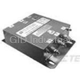
Power Line Filter 50Hz/60Hz 100A 480VAC Threaded Stud Flange Mount 100ADT6
Power Line Filter 50Hz/60Hz 100A 480VAC Threaded Stud Flange Mount 100ADT6S
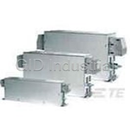
Power Line Filter 50Hz/60Hz 100A 480VAC Terminal Block Flange Mount 100BCF10
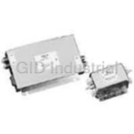
Power Line Filter RFI 100A 80VDC Terminal Block Bulkhead/Rack 100DCB10
Power Line Filter 100A 80VDC Screw Flange Mount 100DCB10B
Power Line Filter 100A 80VDC Screw Flange Mount 100DCB10BF
Request a Quote

The quote request has been received
Close

Facing challenges or have inquiries? Feel free to contact us!
Call Us +1-469-283-2440
What they say about us
FANTASTIC RESOURCE
One of our top priorities is maintaining our business with precision, and we are constantly looking for affiliates that can help us achieve our goal. With the aid of GID Industrial, our obsolete product management has never been more efficient. They have been a great resource to our company, and have quickly become a go-to supplier on our list!
Bucher Emhart Glass
EXCELLENT SERVICE
With our strict fundamentals and high expectations, we were surprised when we came across GID Industrial and their competitive pricing. When we approached them with our issue, they were incredibly confident in being able to provide us with a seamless solution at the best price for us. GID Industrial quickly understood our needs and provided us with excellent service, as well as fully tested product to ensure what we received would be the right fit for our company.
Fuji
HARD TO FIND A BETTER PROVIDER
Our company provides services to aid in the manufacture of technological products, such as semiconductors and flat panel displays, and often searching for distributors of obsolete product we require can waste time and money. Finding GID Industrial proved to be a great asset to our company, with cost effective solutions and superior knowledge on all of their materials, it’d be hard to find a better provider of obsolete or hard to find products.
Applied Materials
CONSISTENTLY DELIVERS QUALITY SOLUTIONS
Over the years, the equipment used in our company becomes discontinued, but they’re still of great use to us and our customers. Once these products are no longer available through the manufacturer, finding a reliable, quick supplier is a necessity, and luckily for us, GID Industrial has provided the most trustworthy, quality solutions to our obsolete component needs.
Nidec Vamco
TERRIFIC RESOURCE
This company has been a terrific help to us (I work for Trican Well Service) in sourcing the Micron Ram Memory we needed for our Siemens computers. Great service! And great pricing! I know when the product is shipping and when it will arrive, all the way through the ordering process.
Trican Well Service
GO TO SOURCE
When I can't find an obsolete part, I first call GID and they'll come up with my parts every time. Great customer service and follow up as well. Scott emails me from time to time to touch base and see if we're having trouble finding something.....which is often with our 25 yr old equipment.
ConAgra Foods