

 Manufacturers
TE CONNECTIVITY 1213001-1

Description
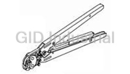
Hand Tools 626 PNEU HD 22-18 PIDG
1213001-1
Part Number
1213001-1
Price
Request Quote
Manufacturer
TE CONNECTIVITY
Lead Time
Request Quote
Category
Tools and Supplies » Assembly Tools
Specifications
Manufacturer
TE Connectivity
Manufacturers Part #
1213001-1
Industry Aliases
1213001-1
Sub-Category
Electronics Assembly Tools
Brand
AMP
Packaging
Package
Factory Pack Quantity
1
Datasheet
DDEController?Action=showdoc&DocId=Specification+Or+Standard%7F408-9586%7FD%7Fpdf%7FEnglish%7FENG_SS_408-9586_D.pdf
211 KiB

Extracted Text
Instruction Sheet PneumaticCrimpingHeads 314269-1,314270-1, 314270-3, 408--9586 1213001-1,and 314537-1 15MAR 10 RevE Pivot Pin(s) or Quick Pin(s) Rollers Pneumatic Crimping Head 314269--1 (Ref) Wire Anvil Tool Holder Jaw Assembly 189766--1 (Ref) Insulation Product: PIDG* Terminals and Splices Anvil Jaw PLASTI--GRIP* Terminals and Splices Wire Size: 26--14 AWG, Solid or Stranded Wire Indenter Product Catalog: 82042 Insulation Jaw Tooling Catalog: 124208 Indenter Jaw Figure 1 This instruction sheet provides recommended 1. INTRODUCTION procedures for wire preparation, crimping head installation, crimping, and maintenance and Pneumatic Crimping Heads 314269--1 (shown in inspection. For information concerning tool setup and Figure 1), 314270--1, 314270--3, 1213001--1, and operation, refer to Customer Manual 409--5862 314537--1 are designed to crimp PIDG Terminals and packaged with the pneumatic tooling assembly. Splices, and PLASTI--GRIP Terminals and Splices onto solid or stranded copper wire size 26--14 AWG. Dimensions in this instruction sheet are in NOTE Refer to Figure 2. The crimping head is used with 626 millimeters [with inch equivalents in brackets]. Pneumatic Tooling Assemblies 189721--1, 189722--1, Figures and illustrations are for reference only or 189724--1 fitted with Tool Holder Assembly i and are not drawn to scale. 189766--1. Reasons for reissue are provided in Section 8, The crimping heads can also be used with “2614” NOTE REVISION SUMMARY. Series Pneumatic Tooling Assemblies. i 2. DESCRIPTION The pneumatic crimping head consists of integral Crimping Head 314270--1 is designed to crimp jaws which close in an arc--like motion. After an NOTE wires with 1.02--2.41 mm [.040--.095 in.] operator locates the terminal or splice between the insulation diameter. crimping jaws and inserts the stripped wire, the tool is i activated to crimp the terminal or splice to the wire. E2010 Tyco Electronics Corporation, Berwyn, PA TOOLING ASSISTANCE CENTER1--800--722--1111 This controlled document is subject to change. 1 of 10 PRODUCT INFORMATION1--800--522--6752 Forlatest revision and Regional CustomerService, All Rights Reserved visit ourwebsite atwww.tycoelectronics.com TE logo and Tyco Electronics are trademarks. LOCB *Trademark. Otherproduct names, logos, orcompany names might be trademarks of theirrespective owners. ORIGINAL INSTRUCTIONS 408-9586 PneumaticCrimpingHeads PLASTI-GRIP PIDG Type PIDG ButtSplice Terminal Terminal 3 Equally Spaced Stripes on Nylon Insulation Restricting WIRESTRIPLENGTH(mm[IN.]) WIRE TERMINAL/SPLICE CRIMPING DOT TERMINALS SPLICES PRODUCT RANGE INSULATION HEAD CODE (AWG) COLORCODE MIN MAX MIN MAX PIDG 3.97 4.78 4.37 5.16 TERMINALS 314537--1 1DOT 26--22 YELLOW [.156] [.188] [.172] [.203] AND SPLICES 22--18 314270--1 1DOT PIDG (Aircraft) TERMINALS RED AND SPLICES 22--16 314270--3 1DOT 5.16 5.94 6.35 7.14 AND PLASTI--GRIP (Commercial) TERMINALS [.203] [.234] [.250] [.281] 314269--1 2DOTS 16--14 BLUE 1DOT PIDG SPLICES 1213001--1 22--18 RED 1RIB NOTE: For PIDG terminalsMS 25036--143through --147(Class1only), use22--18die. WIRESTRIP WIRE INSULATION TERMINAL/SPLICE CRIMPING DOT LENGTH(mm[IN.]) PRODUCT RANGE INSULATION DIAMETER HEAD CODE (AWG) RANGE(mm[IN.] COLORCODE MIN MAX 0.66--1.40 YELLOW WITH 4.75 5.56 26 [.026--.055] BLACK STRIPE [.187] [.219] 314537--1 1DOT 0.79--1.40 YELLOW WITH 24 [.031--.055] BLUE STRIPE 0.97--2.41 RED WITH 22 [.038--.095] GREEN STRIPE 1.17--2.41 RED WITH 314270--1 1DOT 20 [.046--.095] RED STRIPE 1.42--2.41 RED WITH PIDG NYLON 18 INSULATION [.056--.095] WHITE STRIPE RESTRICTING 6.35 7.14 0.79--1.40 YELLOW WITH TERMINALS 24 [.250] [.281] BLUE STRIPE [.031--.055] 0.97--2.79 RED WITH 22 GREEN STRIPE [.038--.110] 314270--3 1DOT 1.17--2.79 RED WITH 20 RED STRIPE [.046--.110] 1.42--2.79 RED WITH 18 WHITE STRIPE [.056--.110] 1.60--3.30 BLUE WITH 16 [.063--.130] BLUE STRIPE 314269--1 2DOTS 1.98--3.30 BLUE WITH 14 GREEN STRIPE [0.78--.130] NOTE: For PIDG insulationrestrictingnylonterminalsMS 7928/1--1through --10, use22--18die. NOTE: RefertoCatalog82042forproductpartnumbers. Figure 2 2 of 10 TycoElectronicsCorporation RevE 408-9586 PneumaticCrimpingHeads 3. HEADINSTALLATIONANDREMOVAL 4. HEADINSTALLATIONANDREMOVAL To avoid personal injury, ALWAYS keep fingers DANGER 3.1. HeadSelection clear of crimping jaws when operating the tool. Never place anything within the crimping jaws The crimping heads are color--coded to match the except terminals or splices. terminal and splice insulation color. Observe the embossed dots on the insulation of finished crimps to 4.1. TerminalCrimpingProcedure ensure that the correct combination of terminal or splice and head was used. See Figure 2. 1. Strip wire to dimensions shown in Figure 2. DO NOT nick wire strand or use wires with nicked or Crimping heads are coated with a preservative to missing conductor strands. NOTE prevent rust and corrosion. Wipe this preservative 2. Open crimping jaws by squeezing rollers from the head, particularly from the crimping i together simultaneously; then position terminal surfaces. between crimping jaws, as shown in Figure 3. The terminal is properly positioned when the tongue of the terminal is under the locator and the wire barrel 3.2. Installation is against the locator. To avoid personal injury, ALWAYS disconnect DANGER 3. After terminal is properly positioned in crimping pneumatic tool from air supply before installing or jaws, release rollers to allow crimping jaws to removing the crimping head. spring shut, holding terminal in place. 4. Insert stripped wire into terminal until the end of DO NOT operate pneumatic tool without the DANGER the conductor butts against the locator. proper crimping head installed. After crimping head is installed, make sure that the quick pins or pivot pins are FULLY tightened to avoid personal PIDG andPLASTI-GRIP Terminals injury and damage to the tool. “C” “B” “C” “B” 1. Remove quick pins from tool holder. Refer to PIDG PIDG Figure 1. Nylon Insulation Terminal Restricting 2. Insert crimping head into tool holder as shown in Terminal Figure 1. “C” “B” 3. After crimping head is properly aligned, insert “B” Equals Wire Barrel PLASTI--GRIP and tighten quick pins (provided with tool holder “C” Equals Insulation Barrel Terminal assembly) or pivot pins (provided with crimping head). See Figure 1. Tyco Electronics recommends using LOCTITE NOTE 242 removable threadlock, or equivalent, to prevent the quick pins or pivot pins from Locator i loosening. Terminal Tongue 4. Connect pneumatic tool to an adequate air Positioned Under supply between 620--690 kPa [90--100 psi]. For Locator specific information on air line requirements and air hose installation, refer to the customer manual packaged with the pneumatic tooling assembly. 3.3. Removal To avoid personal injury, ALWAYS disconnect DANGER pneumatic tool from air supply before removing crimping head. Wire Barrel Against Locator Locator Remove quick pins or pivot pins from crimping head; Figure 3 then remove crimping head from tool holder. RevE TycoElectronicsCorporation 3 of 10 408-9586 PneumaticCrimpingHeads 5. Activate the tool to complete the crimp. Open 4. Crimp terminal or splice as described in crimping jaws by squeezing the rollers together Paragraph 4.1 or 4.2. simultaneously; then remove crimped terminal. 5. Remove terminal or splice. Bend wire forward 6. Refer to Section 5 and Figure 6 for crimp and then backward. The terminal or splice should inspection. retain its grip on the wire. If the wire pulls out, reposition the insulation adjustment pins in the next 4.2. ButtSpliceCrimpingProcedure tighter position and repeat crimping procedure. 1. Strip wire to dimensions shown in Figure 2. DO NOT nick wire strand or use wires with nicked or PIDG ButtSplice missing conductor strands. Window “C” “B” Indent 2. Open crimping jaws by squeezing rollers “B” Equals Wire Barrel together simultaneously. Position splice between “C” Equals Insulation Barrel crimping jaws so that the window indent slides under the locator of crimp head. See Figure 4.A. 3. After splice is properly positioned in crimping Splice Wire Stop jaws, release rollers to allow crimping jaws to spring shut, holding splice in place. A FirstCrimp Locator 4. Insert stripped wire into wire barrel of splice until Window Indent Faces the end of the conductor is against the splice wire Indenter and Slides stop. See Figure 4.A. Under Locator 5. Activate tool to complete the crimp. Open crimping jaws by squeezing rollers together simultaneously; then remove crimped splice. 6. To crimp the other half of the butt splice, reposition it in the crimping jaws and repeat Steps 1 through 5. If the splice cannot be turned, rotate crimping head. See Figure 4.B. 7. Refer to Section 5 and Figure 6 for crimp inspection. End of Conductor Butts Against Splice 4.3. InsulationCrimpAdjustment Wire Stop A. PIDGTerminalsandSplices B SecondCrimp PIDG terminals and splices contain a wire NOTE insulation “grip”. Locator i The insulation crimping section of the crimping head has three positions: 1—Tight; 2—Medium; and 3—Loose. Window Indent on 1. Insert insulation adjustment pins in Position 3. Splice Slides Under SeeFigure5. Locator Always place both adjustment pins in the same NOTE position. See Figure 5. i End of Conductor 2. Place terminal or splice in crimping jaws, as Butts Against Splice shown in Figures 3 and 4. Wire Stop 3. Insert unstripped wire only into the insulation barrel of the terminal or splice. See Figure 4 Figures 3 and 4. 4 of 10 TycoElectronicsCorporation RevE 408-9586 PneumaticCrimpingHeads splices that meet the conditions shown in the “ACCEPT” column. “REJECT” terminations can be avoided through careful use of instructions in Section 4, and by performing regular head maintenance, as described in Section 6. Positions 6. MAINTENANCEANDINSPECTION DANGER To avoid personal injury, ALWAYS disconnect air supply from pneumatic tool before performing maintenance or inspection. Insulation Adjustment Tyco Electronics recommends that a maintenance Pin(s) and inspection program be performed periodically to (Ref) ensure dependable and uniform terminations. The pneumatic crimping head should be inspected once a Figure 5 month. Frequency of inspection should be adjusted to suit your requirements through experience. 6. Repeat adjustment as necessary until desired Frequency of inspection depends on: insulation grip is obtained. DO NOT use a tighter setting than required. 1. The care, amount of use, and handling of the crimping head. B. PLASTI-GRIPTerminals 2. The type and size of the product crimped. PLASTI--GRIP terminals contain only a wire NOTE insulation “support”. 3. The degree of operator skill. i 4. The presence of abnormal amounts of dust and dirt. The insulation crimping section of the crimping head has three positions: 1—Tight; 2—Medium; and 5. Your own established standards. 3—Loose. Each crimping head is thoroughly inspected before Position 3 is for wire having a large insulation packaging. Since there is the possibility of crimping diameter; Position 2 is for wire having a medium head damage during shipment, new crimping heads insulation diameter; and Position 1 is for wire having a should be inspected immediately upon arrival at your small insulation diameter. facility. 1. Perform insulation crimp adjustment by placing adjustment pins in Position 3 (loose), as shown in 6.1. DailyMaintenance Figure 5. Tyco Electronics recommends that each operator be 2. Crimp the terminal as described in Paragraph responsible for the following steps of daily 4.1, Terminal Crimping Procedure. maintenance: 3. Remove crimped terminal from crimping jaws 1. Remove dust, moisture, and other contaminants and visually inspect the insulation barrel crimp of with a clean, soft brush, or a lint--free cloth. Do the terminal. The insulation barrel crimp should be NOT use objects that could damage the head. in contact with and should support the wire insulation. 2. Make sure that all pins, rings, and other components are in place and secure. If the insulation barrel crimp does not provide “support” for wire insulation, place adjustment pins To avoid personal injury and damage to the tool, DANGER in Position 2 (medium) and repeat the crimp make sure quick pins or pivot pins are fully procedure. tightened. 4. Repeat adjustment as necessary until desired insulation support is obtained. DO NOT use a tighter setting than required. 3. Make certain all surfaces are protected with a thin coat of any good SAE 20 motor oil. Do NOT oil excessively. 5. CRIMPINSPECTION Inspect crimped terminals and splices by checking the 4. When the head assembly is not in use, store it features described in Figure 6. Use only terminals or in a clean dry, area. RevE TycoElectronicsCorporation 5 of 10 408-9586 PneumaticCrimpingHeads CrimpInspection 8 ACCEPT REJECT 4 4 7 5 8 4 5 5 3 PIDG 1 3 Insulation 1 Restricting 2 6 Wire Terminals 6 2 1 2 2 Range 1 Stamped 5 PIDG and Under PLASTI--GRIP Tongue Terminals 4 7 3 Wire Range Stamped 5 Under Tongue 8 9 1 2 5 4 6 2 1 4 7 PIDG 1 2 Butt Splice Wire 6 Stop 2 2 8 2 5 1 2 6 2 1 6 1 3 Wire Range 6 3 Stamped Here 9 Wire Range 7 6 Stamped Here 1 1 Insulationbarrelisinfirmcontact withwireinsulation. Wireinsulationextruded. (Insulationcrimptootight onPIDG terminals.) SeeParagraph4.3. 2 Correct color code, dot code, andtoolcombination. 2 Wrongdot codeandcolor codecombination. Seechart, Figure2. 3 Wiresizeiswithinwirerangestampedonterminaltongueor 3 Wiresizeisnot withinwirerangestampedonterminaltongue splice. or splice. 4 Crimpcenteredonwirebarrel. 4 Crimpnot centeredonwirebarrel. (Terminalwasnot butted against locator. SeeFigure3.) 5 Endof conductor isflushwith, or extendsbeyondendof 5 Endof conductor isnot flushwithor extendingbeyondendof terminalwirebarrel. wirebarrel. (Checkfor correct striplength.) 6 Endof conductor against wirestopof splice. 6 Excessiveflashor extrudedinsulation. (Wrongtool, terminal, or NOTE: If conductor isnot against wirestop, conductor must splicecombinationused, or damageddies.) SeeFigure2. at least beflushwith, or extendslightlybeyondwirebarrel of splice. 7 Nickedor missingconductor strands. 7 Wireinsulationdoesnot enter wirebarrel. 8 Wirenot fullyinsertedor wrongstriplength. Wireinsulationenteredwirebarrel. Checkfor correct wiresize 9 or striplength. Figure 6 6 of 10 TycoElectronicsCorporation RevE 408-9586 PneumaticCrimpingHeads 6.2. PeriodicInspection Wipe excess grease from crimping head, particularly from jaw closure areas. Grease transferred from jaw Regular inspections should be performed by quality closure area onto certain terminations may affect the control personnel. A record of scheduled inspections electrical characteristics of an application. should remain with the crimping heads or be supplied to supervisory personnel responsible for the crimping 6.4. GagingtheCrimpingChamber heads. Though recommendations call for at least one This inspection requires the use of plug gages inspection a month, the frequency should be based conforming to the dimensions shown in Figure 8. Tyco on amount of use, working conditions, operator Electronics does not manufacture or market these training and skill, and your established company gages. policies. These inspections should include a visual inspection (Paragraph 6.3) and a crimping chamber inspection (Paragraph 6.5). SuggestedPlugGageDesignWireBarrel Crimp 6.3. VisualInspection Crimping Heads 314269--1, 314270--1, 1. Remove all lubrication and accumulated film by 314270--3, and 314537--1 immersing the crimping head in a suitable commercial degreaser that will not affect paint or GO Dia NO--GO Dia plastic. 2. Make certain all components are in place. If replacements are necessary, refer to Figure 10. Jaw Closure 50.8 [2.0] Configuration Min. Typ. 3. Check all bearing surfaces for wear. Make sure the rollers turn freely with minimal resistance. Replace worn parts. 4. Inspect crimp area for flattened, chipped, or broken areas. See Figure 7. Replace worn or Crimping Head 1213001--1 Only damaged parts. 3.454 3.454 [.136] [.136] Pitted NO--GO Max. Max. GO Dim. Chipped Edge Dim. 31.75 [1.25] 3.962 3.962 Min. Typ. [.156] [.156] Max. Max. 12.7 [.50] Min. Typ. Die Closure Configuration Flattened JAWCLOSURE GAGEELEMENTDIAMETERS CRIMPING Area Broken Crimping Head DIMENSIONS (mm[IN.]) HEAD Corner 314269--1 (Ref) (mm[IN.]) GO NO--GO 314270--1 2.769--2.921 2.769--2.776 2.918--2.921 Figure 7 314270--3 [.1090--.1150] [.1090--.1093] [.1149--.1150] 3.023--3.175 3.023--3.030 3.172--3.175 Lubricate all pins, pivot points, and bearing surfaces 314269--1 [.1190--.1250] [.1190--.1193] [.1249--.1250] with a high quality grease. Tyco Electronics recommends the use of Molykote grease, which is a 1.600--1.752 1.600--1.608 1.750--1.752 314537--1 commercially available lubricant. Lubricate according [.0630--.0690] [.0630--.0633] [.0689--.0690] to the following schedule: 2.616--2.718 2.616--2.624 2.715--2.718 1213001--1 [.1030--.1070] [.1030--.1033] [.1069--.1070] Head used in daily production -- lubricate daily Head used daily (occasional) -- lubricate weekly Head used weekly -- lubricate monthly Figure 8 (cont’d) RevE TycoElectronicsCorporation 7 of 10 408-9586 PneumaticCrimpingHeads 4. Align the NO--GO element and try to insert it SuggestedPlugGageDesignInsulationCrimp into the chamber. The element may start entry, but it must not pass completely through the crimping GO Dim. NO--GO Dim. chamber. 5. Repeat this procedure for the insulation crimping NO GO section using a plug gage as shown in Figure 9.B. GO Jaw Closure If the crimping chamber passes the gage inspection, 6.35 Configuration [.250] the crimping head is considered dimensionally correct 3.18 Typ. and should be lubricated with a THIN coat of any [.125] good SAE 20 motor oil. If the crimping chamber does not conform to the plug gage conditions, contact your JAWCLOSURE GAGEELEMENTDIAMETERS CRIMPING local Tyco Electronics Representative or refer to DIMENSIONS (mm[IN.]) HEAD Section 7, REPLACEMENT AND REPAIR. (mm[IN.]) GO NO--GO 0.965--1.473 0.965--0.973 1.471--1.473 For additional information about the use of a plug 314270--1 [.0380--.0580] [.0380--.0383] [.0579--.0580] gage, see Instruction Sheet 408--7424. 0.762--1.270 0.762--0.770 1.267--1.270 314270--3 [.0300--.0500] [.0300--.0303] [.0499--.0500] 7. REPLACEMENTANDREPAIR 1.016--1.524 1.016--1.024 1.521--1.524 314269--1 Replacement parts and recommended spares are [.0400--.0600] [.0400--.0403] [.0599--.0600] listed in Figure 10. The recommended spares should 0.762--1.270 0.762--0.770 1.267--1.270 be stocked for immediate replacement. 314537--1 [.0300--.0500] [.0300--.0303] [.0499--.0500] Order replacement parts through your Tyco 0.762--1.270 0.762--0.770 1.267--1.270 1213001--1 Electronics Representative, or call 1--800--526--5142, [.0300--.0500] [.0300--.0303] [.0499--.0500] or send a facsimile of your purchase order to Figure 8 (end) 1--717--986--7605, or write to: CUSTOMER SERVICE (38--35) Disconnect air supply and remove crimping head DANGER TYCO ELECTRONICS CORPORATION from tool before inspecting crimping PO BOX 3608 chambers. HARRISBURG PA 17105--3608 For further repair and replacement information, call 1. Remove oil and dirt from the jaw bottoming the Tooling Assistance Center number at the bottom surfaces and plug gage element surfaces. of page 1. 2. Close wire barrel crimping jaws until they are bottomed, but not under pressure. 8. REVISIONSUMMARY 3. Align GO element with wire barrel crimping section. Push element straight into crimping Since the previous release of this sheet, the following chamber without using force. The GO element changes were made: must pass completely through the chamber as shown in Figure 9.A. S Added “Original Instructions” 8 of 10 TycoElectronicsCorporation RevE 408-9586 PneumaticCrimpingHeads Detail A Detail B InspectionofWireBarrel InspectionofInsulation CrimpingSection CrimpingSection Wire Barrel Jaws Adjustment Bottomed But Not Pins in Under Pressure Position 1 (Ref) Insulation Jaws Bottomed But Not Under Pressure GO Element Must Pass Completely Through the Crimping Chamber NO--GO Element May Enter Partially, But Must Not Pass Through the Crimping Chamber Figure 9 RevE TycoElectronicsCorporation 9 of 10 408-9586 PneumaticCrimpingHeads 19 21 Ref 2 3 1 1Ref 12 13 4 5 11 6 9 7 8 10 Ref 18 20 10 Ref 14 15 16 CrimpingHead 314269-1 Shown (Ref) 17 CUSTOMERREPLACEMENTPARTS ITEM PARTNO.FORCRIMPING HEAD QTYPER DESCRIPTION NO. HEAD 314269--1 314270--1, --3 314537--1 1213001--1 1 314560--1 314560--2 314560--3 1--306064--4 INDENTER 1 2 39085 39085 39085 39085 PIN, Pivot 1 3 314253--1 314253--1 314253--1 314253--1 SPRING 1 4 45965--6 302993 3--304052--6 4--304052--6 LOCATOR 1 5 9--305927--1 9--305927--1 3--306105--9 9--305927--1 SCREW, 8--32x.33 1 6 302994 302994 302994 302994--1 HOUSING, Stop 1 7 301201 301201 301201 301201 SPRING, Compression 1 8 3--23628--4 3--23628--4 3--23628--4 3--23628--4 PIN, Str, Grv.2500Dia 2 9 21048--7 21048--7 21048--7 21048--7 RING, Retaining 4 10 314561--1 314561--2 314561--3 1--306063--4 ANVIL 1 11 314479--1 314479--1 314479--1 314479--1 ROLLER 4 12 3--23619--7 3--23619--7 3--23619--7 3--23619--7 PIN, Str, Grv.1875Dia 2 13 21045--3 21045--3 21045--3 21045--3 RING, Retaining 4 14 39208 39208 39208 39208 RING 6 15 39207 39207 39207 39207 PIN, Adjustment 2 16 314477--1 314477--1 314477--1 314477--1 LINK 1 17 314477--2 314477--2 314477--2 314477--2 LINK 1 18 314563--1 314563--2z 314563--3 1--306065--5 ANVIL, Insulation 1 19 314562--1 314562--3 1--306066--5 INDENTER, Insulation 1 314562--2z 20 — 314563--4H — — ANVIL, Insulation 1 21 — 314562--4H — — INDENTER, Insulation 1 z For Crimping Head 314270--3 only. H For Crimping Head 314270--1 only. Figure 10 10 of 10 TycoElectronicsCorporation RevE
Frequently asked questions
How does Electronics Finder differ from its competitors?

Is there a warranty for the 1213001-1?
Which carrier will Electronics Finder use to ship my parts?
Can I buy parts from Electronics Finder if I am outside the USA?
Which payment methods does Electronics Finder accept?
Why buy from GID?

Quality
We are industry veterans who take pride in our work

Protection
Avoid the dangers of risky trading in the gray market

Access
Our network of suppliers is ready and at your disposal

Savings
Maintain legacy systems to prevent costly downtime

Speed
Time is of the essence, and we are respectful of yours
Related Products

Torque Wrenches Are Used To Properly Install Or Disassemble The Connectors 1055419-1
Tool For RF Connectors 1055442-1
Tool For RF Connectors 1055443-1
Insertion Tool For RF Connectors 1055447-1
Insertion Tool For RF Connectors 1055448-1
Assembly Tools, Sma Right Angle Cable Plugs 1055451-1
Request a Quote

The quote request has been received
Close

Facing challenges or have inquiries? Feel free to contact us!
Call Us +1-469-283-2440
What they say about us
FANTASTIC RESOURCE
One of our top priorities is maintaining our business with precision, and we are constantly looking for affiliates that can help us achieve our goal. With the aid of GID Industrial, our obsolete product management has never been more efficient. They have been a great resource to our company, and have quickly become a go-to supplier on our list!
Bucher Emhart Glass
EXCELLENT SERVICE
With our strict fundamentals and high expectations, we were surprised when we came across GID Industrial and their competitive pricing. When we approached them with our issue, they were incredibly confident in being able to provide us with a seamless solution at the best price for us. GID Industrial quickly understood our needs and provided us with excellent service, as well as fully tested product to ensure what we received would be the right fit for our company.
Fuji
HARD TO FIND A BETTER PROVIDER
Our company provides services to aid in the manufacture of technological products, such as semiconductors and flat panel displays, and often searching for distributors of obsolete product we require can waste time and money. Finding GID Industrial proved to be a great asset to our company, with cost effective solutions and superior knowledge on all of their materials, it’d be hard to find a better provider of obsolete or hard to find products.
Applied Materials
CONSISTENTLY DELIVERS QUALITY SOLUTIONS
Over the years, the equipment used in our company becomes discontinued, but they’re still of great use to us and our customers. Once these products are no longer available through the manufacturer, finding a reliable, quick supplier is a necessity, and luckily for us, GID Industrial has provided the most trustworthy, quality solutions to our obsolete component needs.
Nidec Vamco
TERRIFIC RESOURCE
This company has been a terrific help to us (I work for Trican Well Service) in sourcing the Micron Ram Memory we needed for our Siemens computers. Great service! And great pricing! I know when the product is shipping and when it will arrive, all the way through the ordering process.
Trican Well Service
GO TO SOURCE
When I can't find an obsolete part, I first call GID and they'll come up with my parts every time. Great customer service and follow up as well. Scott emails me from time to time to touch base and see if we're having trouble finding something.....which is often with our 25 yr old equipment.
ConAgra Foods