

 Manufacturers
TE CONNECTIVITY 1278219-1

Description
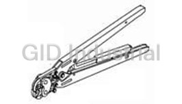
Light Crimp Plus SC Simplex Connector
1278219-1
Part Number
1278219-1
Price
Request Quote
Manufacturer
TE CONNECTIVITY
Lead Time
Request Quote
Category
Tools and Supplies » Assembly Tools
Specifications
Manufacturer
TE Connectivity
Manufacturers Part #
1278219-1
Industry Aliases
1278219-1
Sub-Category
Electronics Assembly Tools
Brand
AMP
Packaging
Package
Factory Pack Quantity
1
Datasheet
DDEController?Action=showdoc&DocId=Specification+Or+Standard%7F408-4471%7FM%7Fpdf%7FEnglish%7FENG_SS_408-4471_M.pdf
482 KiB

Extracted Text
Instruction Sheet LightCrimpPlus*SCSimplex 408--4471 FiberOpticConnectorKits 18 Mar 11 RevM VerifythatInstruction Sheet(408-Series) Strain Pertainsto ConnectorKitBeing Terminated Relief To Verify, Refer to Product Drawing for Applicable Instruction Sheet at: Inner www.te.com Eyelet (Search by Connector Kit Part Number, Crimp Click on the Part Number, Click on Product Drawing) Eyelet Bare Buffer Plunger Boot Dust CapG Connector Assembly Small Clear Tubing Tubing Termination CoverG Connector Housing GConnector kit is shipped with these installed onto connector assembly. Keep them in place until ready for assembly. Figure 1 1. INTRODUCTION 5.4. 900-mm EasyStrip orSemi-TightBuffered Fiber LightCrimp Plus SC simplex fiber optic connector kits Read these instructions thoroughly before assembling are designed to be applied to fiber optic cable. The the connector kits. connectors are used with singlemode or multimode 125--mm glass fiber cable. These kits can be used All numerical values in this instruction sheet are NOTE with any of the following media (paragraph of in metric units. Dimensions are in millimeters. assembly procedure is indicated next to media). Figures are for reference only and are not drawn i to scale. 5.1. 900-mm BareBuffered Fiber Reasons for reissue of this instruction sheet are 5.2. 250-mmCoated Fiber provided in Section 6, REVISION SUMMARY. 5.3. 2.5- to 3.0-mm LooseJacketed Cable 2. DESCRIPTION (See Figure 1) NOTE: Any jacketed cable used with SC connectors must allow for the axial movement of the buffered Each connector kit consists of a connector housing, fiber in the jacket which occurs when the connector is connector assembly, strain relief, inner eyelet, crimp mated to another connector or device. Certain cable eyelet, and clear tubing. Each kit is also supplied with constructions do not allow axial movement and are a bare buffer boot and small tubing to compensate for not suitable for use with SC connectors. Refer to small diameter cable. Also included, assembled onto Inspection Specification 129--1496 for a method of the connector, are a termination cover for the ferrule determining whether a given cable construction allows (front of connector) and a plunger dust cap for the axial movement (result of the buffer pull test). plunger (rear of connector). E2011 Tyco Electronics Corporation, a TE Connectivity Ltd. Company TOOLING ASSISTANCE CENTER 1--800--722--1111 This controlled document is subject to change. 1 of 17 All Rights Reserved PRODUCT INFORMATION 1--800--522--6752 For latest revision and Regional Customer Service, visit our website at www.te.com TE Connectivity, TE connectivity (logo), and TE (logo) are trademarks. LOCB *Trademark. Other logos, product and/or Company names may be trademarks of their respective owners. 408-4471 3. SAFETYPRECAUTIONS 5. ASSEMBLYPROCEDURE To avoid personal injury, ALWAYS wear eye DANGER protection when working with optical fibers. 5.1. 900-mm BareBufferedFiber NEVER look into the end of terminated or unterminated fibers. Laser radiation is invisible KitComponentsRequired but can damage eye tissue. NEVER eat, drink, or (Discard Other Components) smoke when working with fibers. This could lead to ingestion of glass particles. Plunger Dust CapG BE VERY CAREFUL to dispose of fiber ends DANGER Connector properly. The fibers create slivers that can easily Assembly puncture the skin and cause irritation. Bare Buffer Termination Boot CoverG DO NOT use defective or damaged components. CAUTION Replace them with new components. ! Connector Housing 4. REQUIREDTOOLSANDMATERIALS —Cable Holder Assembly 1278023--1 or GConnector kit is shipped with these installed onto connector 2064540--1 assembly. Keep them in place until ready for assembly. —Miller Strip Tool 1754708--1 —Alcohol Fiber Wipe Packet 501857--2 —isopropyl alcohol A. Preparing900-mm BareBufferedFiber (Figure 2) —Fiber Optic Cleaver 1871696--1 (408--10086) 1. Slide the bare buffer boot (small diameter end first) over the buffer. See Figure 2, Detail A. —LightCrimp Plus SC Die Set with Crimping Tool 492782--1 (consists of Die Set 492783--1 and 2. Remove the plunger dust cap from the PRO--CRIMPER* III Hand Tool 2064431--1) connector assembly, and discard. Can be used for terminating all fiber and cable. 3. Push the connector assembly into the holder of —LightCrimp* Inline Splice Die Set with Crimping the cable holder assembly with the termination Tool 2064603--1 (consists of Die Set 1985766--1 cover facing outward. See Figure 2, Detail B. Make and PRO--CRIMPER III Hand Tool 2064431--1) sure that the connector butts against the lip on the Can only be used for terminating 900--mm arm of the cable holder assembly. Slide the fiber bare buffered fiber, 250--mm coated fiber, and into the channel marked “BUFFER”. Make sure 1.6-- to 2.0--mm jacketed cable. that the tip of the buffer butts against the end of the channel. 4. Mark the buffer at each cross--slot of the channel. See Figure 2, Detail B. Remove the buffer from the cable holder assembly. 5. Using the strip tool, strip the fiber to the first mark. It is recommended holding the strip tool at an angle to the fiber and stripping the fiber in three sections. See Figure 2, Detail C. Clean the fiber with an alcohol fiber wipe to remove the fiber coating residue. Before using the strip tool, make sure that the “V” CAUTION opening is clean; otherwise the fiber could break. Only use isopropyl alcohol on the tool. ! 2 of 17 RevM 408-4471 B. Cleaving (Figure 3) 4. Squeeze the handles of the hand tool until the ratchet releases. Allow the handles to open fully. 1. Open the fiber clamp of the fiber optic cleaver. Then: Press the button, and slide the carriage back If using Die Set 492783--1, slowly close the (toward the fiber clamp). Then move the fiber slide handles until you hear 2 clicks from the ratchet. back until it stops. If using Die Set 1985766--1, slowly close the 2. Place the stripped fiber into the slot so that the handles until you hear 3 clicks from the ratchet. end of the buffer is at the 8--mm marking. See Figure 3, Detail A. 5. With the connector assembly in the cable holder assembly, position the ferrule or termination cover 3. While applying pressure on the buffer, carefully in the upper cavity of the front die and the plunger slide the fiber slide forward (toward the carriage) in the upper cavity of the rear die. See Figure 4, until it stops. See Figure 3, Detail B. Detail C. 4. Gently close the fiber clamp, and slide the carriage forward. DO NOT touch the button while The arrows marked on the front die indicate the CAUTION sliding the carriage. See Figure 3, Detail C. direction that the ferrule or termination cover must be pointing when the connector is 5. Open the fiber clamp, and move the fiber slide ! positioned in that cavity. For proper placement, back until it stops. and to avoid damage to the fiber, observe the 6. Remove the cleaved fiber, and properly dispose direction of the arrows. Refer to Figure 4, Detail of the scrap fiber. C and Figure 5, Detail A. DO NOT attempt to clean the fiber after it has CAUTION 6. Gently push the buffer toward the connector been cleaved. assembly to make sure that the fiber is still ! bottomed, then slowly squeeze the tool handles together until the ratchet releases. Allow the handles to open fully, and remove connector from C. Crimping (Figures4 and 5) the dies. 1. Open the cable clamp of the cable holder 7. Position the plunger of the connector assembly assembly, and position the buffer (with the cleaved in the first (smallest) cavity of the front die with the end facing the connector) inside the clamp. Move knurl against the edge of the groove in the die and the buffer so that the end of the fiber is even with the ferrule or termination cover pointing in the the front of the arm of the cable holder assembly, direction of the arrow. See Figure 5, Detail A. and holding the buffer in place, close the clamp. See Figure 4, Detail A. 8. Slowly squeeze the tool handles together until the ratchet releases. Allow the handles to open 2. Carefully insert the fiber into the plunger of the fully, and remove the connector assembly from the connector assembly until the fiber bottoms against die. the internal fiber. Make sure that the remaining mark on the buffer enters the plunger. The 9. Slide the bare buffer boot over the plunger until resultant bend in the buffer should hold the fiber the boot butts against the connector assembly. See against the internal fiber. See Figure 4, Detail B. Figure 5, Detail B. It is important that the fiber bottoms against, and 10. Remove the connector assembly from the NOTE remains against, the internal fiber. If the mark cable holder assembly. does not enter the plunger or if the fiber does not i 11. Align the key of the connector housing with the seem to bottom against the internal fiber, the chamfered edges of the connector assembly. Slide fiber may be caught on internal guides. Rotating the housing over the assembly until it snaps in the connector and backing the fiber out a small place. See Figure 5, Detail C. amount and re--entering may help. However, if the mark will not enter the plunger, the fiber must DO NOT force the components together. They NOTE be re--stripped. are designed to fit only one way. Make sure that the fiber does not pull rearward i from the contact (with the internal fiber) during the crimping operation. 3. If using Die Set 492783--1, remove (and retain) The assembly procedure for 900--mm bare buffered the termination cover. fiber is now complete. If using Die Set 1985766--1, do not remove the termination cover. "If connecting connectors, refer to Paragraph 5.5. RevM 3 of 17 408-4471 B. Cleaving (Figure 3) 5.2. 250-mmCoatedFiber 1. Open the fiber clamp of the fiber optic cleaver. Press the button, and slide the carriage back KitComponentsRequired (toward the fiber clamp). Then move the fiber slide (Discard Other Components) back until it stops. Plunger 2. Place the stripped fiber into the slot so that the Dust CapG end of the buffer is at the 8--mm marking. See Connector Figure 3, Detail A. Assembly 3. While applying pressure on the buffer, carefully Bare Buffer Termination slide the fiber slide forward (toward the carriage) Boot CoverG until it stops. See Figure 3, Detail B. 4. Gently close the fiber clamp, and slide the carriage forward. DO NOT touch the button while sliding the carriage. See Figure 3, Detail C. Small 5. Open the fiber clamp, and move the fiber slide Tubing Connector back until it stops. Housing 6. Remove the cleaved fiber, and properly dispose of the scrap fiber. GConnector kit is shipped with these installed onto connector assembly. Keep them in place until ready for assembly. CAUTION DO NOT attempt to clean the fiber after it has been cleaved. ! A. Preparing250-mmCoatedFiber (Figure 2) C. Crimping (Figures4 and 5) 1. Slide the bare buffer boot (small diameter end first) over the fiber. See Figure 2, Detail A. 1. Open the cable clamp of the cable holder assembly, and position the fiber (with the cleaved 2. Remove the plunger dust cap from the end facing the connector) inside the clamp. Move connector assembly, and discard. the fiber so that the end of the fiber is even with the front of the arm of the cable holder assembly, 3. Insert the small (white) tubing into the plunger of and holding the fiber in place, close the clamp. See the connector assembly until the tubing bottoms. Figure 4, Detail A. See Figure 2, Detail A. 2. Carefully insert the fiber into the plunger of the 4. Push the connector assembly into the holder of connector assembly until the fiber bottoms against the cable holder assembly with the termination the internal fiber. Make sure that the remaining cover facing outward. See Figure 2, Detail B. Make mark on the fiber enters the plunger. The resultant sure that the connector butts against the lip on the bend in the fiber should hold the fiber against the arm of the cable holder assembly. Slide the fiber internal fiber. See Figure 4, Detail B. into the channel marked “BUFFER”. Make sure that the tip of the fiber butts against the end of the Also, the fiber coating must enter the small tubing channel. that was installed in Step 3 of Paragraph 5.2.A. Make sure that the start of the fiber coating is not 5. Mark the fiber at each cross--slot of the channel. caught on the entry of the small tubing. See Figure 2, Detail B. Then, remove the fiber from the cable holder assembly. It is important that the fiber bottoms against, and NOTE remains against, the internal fiber. If the mark 6. Using the strip tool, strip the fiber to the first does not enter the plunger or if the fiber does not mark. It is recommended holding the strip tool at i seem to bottom against the internal fiber, the an angle to the fiber and stripping the fiber in three fiber may be caught on internal guides. Rotating sections. See Figure 2, Detail C. Clean the fiber the connector and backing the fiber out a small with an alcohol fiber wipe to remove the fiber buffer amount and re--entering may help. However, if residue. the mark will not enter the plunger, the fiber must be re--stripped. Before using the strip tool, make sure that the “V” CAUTION opening is clean; otherwise the fiber could break. Make sure that the fiber does not pull rearward Only use isopropyl alcohol on the tool. from the contact with the internal fiber during the ! crimping operation. 4 of 17 RevM 408-4471 3. If using Die Set 492783--1, remove (and retain) 7. Position the plunger of the connector assembly the termination cover. in the first (smallest) cavity of the front die with the knurl against the edge of the groove in the die and If using Die Set 1985766--1, do not remove the the ferrule or termination cover pointing in the termination cover. direction of the arrow. See Figure 5, Detail A. 4. Squeeze the handles of the hand tool until the 8. Slowly squeeze the tool handles together until ratchet releases. Allow the handles to open fully. the ratchet releases. Allow the handles to open Then: fully, and remove the connector assembly from the If using Die Set 492783--1, slowly close the die. handles until you hear 2 clicks from the ratchet. 9. Slide the bare buffer boot over the plunger until If using Die Set 1985766--1, slowly close the the boot butts against the connector assembly. See handles until you hear 3 clicks from the ratchet. Figure 5, Detail B. 5. With the connector assembly in the cable holder 10. Remove the connector assembly from the assembly, position the ferrule or termination cover cable holder assembly. in the upper cavity of the front die and the plunger in the upper cavity of the rear die. See Figure 4, 11. Align the key of the connector housing with the Detail C. chamfered edges of the connector assembly. Slide the housing over the assembly until it snaps in The arrows marked on the front die indicate the CAUTION place. See Figure 5, Detail C. direction that the ferrule or termination cover must be pointing when the connector is ! DO NOT force the components together. They NOTE positioned in that cavity. For proper placement, are designed to fit only one way. and to avoid damage to the fiber, observe the direction of the arrows. Refer to Figure 4, Detail i C and Figure 5, Detail A. 6. Gently push the fiber toward the connector assembly to make sure that the fiber is still The assembly procedure for 250--mm coated fiber is bottomed, then slowly squeeze the tool handles now complete. together until the ratchet releases. Allow the handles to open fully, and remove the connector from the dies. "If connecting connectors, refer to Paragraph 5.5. RevM 5 of 17 408-4471 Figure2: PreparingtheFiber Figure3: Cleaving Detail A Detail A Stripped Fiber in Slot Buffer (900--mmBare Fiber) or Fiber (250--mm Coated Fiber) Small Diameter End of Bare Buffer Boot For 250--mm Small Coated Fiber Tubing Plunger Detail B End of Buffer at Mark BufferorFiber 8--mm Marking at Cross--Slots Tip of Buffer (900--mm Bare Fiber) or Fiber (250--mm Coated Fiber) Detail B Against End of Channel Connector Assembly Cable Holder in Holder with Assembly Termination Cover Facing Outward Detail C Slide Fiber Slide Strip Fiber in Forward Sections to First Mark Strip Tool Detail C Fiber Clamp Closed Hold Strip Tool at 45_ Angle (Approx) to Fiber Direction of Strip Slide Carriage Forward 6 of 17 RevM 408-4471 Figure4: Crimping Figure5: Crimping Detail A Detail A Buffer (900--mm Bare Fiber) or Fiber (250--mm Coated Fiber) Held in Cable Clamp Plunger in First Cavity of Front Die Cleaved End of Fiber Even with Front of Arm of Cable Holder Assembly Knurl Against Edge of Groove in Die Detail B Termination Cover Facing Outward For Die Set 1985766--1, Termination Cover; For Die Set 492783--1, Ferrule Pointing in Direction of Arrow Fiber Bottomed Detail B Bare Buffer Boot Over in Plunger Plunger and Against Connector Assembly Bend Formed to Hold End of Fiber in Place Termination Cover (Shown) Detail C For Die Set 1985766--1, Termination Cover; For Die Set 492783--1, Ferrule In Upper Cavity of Front Die and Detail C Pointing in Direction of Arrow Key of Connector Housing Aligned with Chamfered Edges of Connector Assembly s Slide Housing Over Assembly Plunger in Upper Cavity of Rear Die RevM 7 of 17 408-4471 8. Slide the buffer into the channel marked 5.3. 2.5- to3.0-mmLooseJacketedCable “BUFFER” on the cable holder assembly. Make sure that the tip of the buffer butts against the end of the channel. See Figure 7, Detail C. KitComponentsRequired (Discard Other Components) 9. Mark the buffer at each cross--slot of the channel and at the right end of the channel (total of Plunger three marks). See Figure 7, Detail C. Remove the Dust CapG buffer from the cable holder assembly. Connector 10. Using the strip tool, strip the buffer to the first Assembly Strain mark. It is recommended holding the strip tool at Termination Relief an angle to the buffer and stripping the buffer in CoverG three sections. See Figure 7, Detail D. Clean the fiber with an alcohol fiber wipe to remove fiber coating residue. Inner Eyelet Before using the strip tool, make sure that the “V” CAUTION opening is clean; otherwise the fiber could break. Crimp Only use isopropyl alcohol on the tool. Eyelet ! Connector Housing B. Cleaving (Figure 8) GConnector kit is shipped with these installed onto connector 1. Open the fiber clamp of the fiber optic cleaver. assembly. Keep them in place until ready for assembly. Press the button, and slide the carriage back (toward the fiber clamp). Then move the fiber slide back until it stops. A. Preparing2.5- to3.0-mmLooseJacketedCable 2. Place the stripped buffer into the slot so that the (Figures6 and 7) end of the fiber is at the 8--mm marking. See 1. Slide the strain relief (small diameter end first) Figure 8, Detail A. over the cable. See Figure 6, Detail A. 3. While applying pressure on the fiber, carefully slide the fiber slide forward (toward the carriage) 2. Remove the plunger dust cap from the until it stops. See Figure 8, Detail B. connector assembly, and discard. 4. Gently close the fiber clamp, and slide the 3. Push the connector assembly into the holder of carriage forward. DO NOT touch the button while the cable holder assembly with the termination sliding the carriage. See Figure 8, Detail C. cover facing outward. See Figure 6, Detail B. Make sure that the connector is sitting flat against the 5. Open the fiber clamp, and move the fiber slide arm of the cable holder assembly. Slide the cable back until it stops. into the channel marked “CABLE.” Make sure that the tip of the jacket butts against the end of the 6. Remove the cleaved fiber, and properly dispose channel. of the scrap fiber. 4. Mark the cable at the right--most cross--slot of DO NOT attempt to clean the fiber after it has CAUTION the channel. See Figure 6, Detail B. Then, remove been cleaved. the cable from the cable holder assembly. ! 5. Using the strip tool, cut through the jacket at the mark. See Figure 6, Detail C. C. Crimping (Figures9, 10, and 11) 6. Remove the jacket segment, gather the strength Only use Die Set 492783--1 to terminate 2.5-- to members in a bundle, and fold them back along 3.0--mm loose jacketed cable. the jacket. See Figure 6, Detail D. 1. Open the cable clamp of the cable holder 7. Slide the crimp eyelet over the buffer and onto assembly, and position the buffer (with the cleaved the strength members to hold them in place. Slide end facing the connector) inside the clamp. Move the inner eyelet, non--flanged end first, onto the the buffer so that the end of the fiber is even with buffer. Push the inner eyelet under the strength the front of the arm of the cable holder assembly, members until the face is flush with the front of the and holding the buffer in place, close the clamp. crimp eyelet. See Figure 7, Detail B. See Figure 9, Detail A. 8 of 17 RevM 408-4471 2. Carefully insert the buffer into the plunger of the Make sure that a space of 3 to 5 mm exists CAUTION connector assembly until the fiber bottoms against between the face of the inner eyelet (shown in the internal fiber. See Figure 9, Detail B. Make Figure 7, Detail B) and the plunger (rear of ! sure that the remaining mark on the buffer enters connector assembly). Refer to Figure 10, the plunger. The resultant bend in the buffer should Detail A. hold the fiber against the internal fiber. Only a slight bend is necessary. Failure to ensure that this space exists may result CAUTION in improper connector performance when mated to a connector. NOTE It is important that the fiber bottoms against, and ! remains against, the internal fiber. If the mark does not enter the plunger or if the fiber does not i 8. Position the plunger of the connector assembly seem to bottom against the internal fiber, the in the first (smallest) cavity of the front die with the fiber may be caught on internal guides. Rotating knurl against the edge of the groove in the die and the connector and backing the buffer out a small the ferrule pointing in the direction of the arrow. amount and re--entering may help. However, if See Figure 10, Detail B. the mark will not enter the plunger, the fiber must be re--stripped. 9. Slowly squeeze the tool handles together until the ratchet releases. Allow the handles to open Make sure that the fiber does not pull rearward fully, and remove the connector assembly from the from the contact with the internal fiber during the die. crimping operation. 10. Slide the crimp eyelet away from the connector assembly until the strength members are free, then 3. Squeeze the handles of the hand tool until the slide the crimp eyelet toward the connector until ratchet releases. Allow the handles to open fully. the strength members and crimp eyelet butt Slowly close the handles until you hear 2 clicks against the connector. See Figure 10, Detail C. from the ratchet. 11. Position the crimp eyelet against the last cavity of the front die with the ferrule pointing in the 4. Remove the termination cover from the direction of the arrow. Make sure that the connector assembly, and retain. connector assembly is butted against the die. The crimp eyelet will move into the cavity when the dies 5. With the connector assembly in the cable holder are closed. See Figure 11, Detail A. Slowly assembly, position the ferrule in the upper cavity of squeeze the tool handles together until the ratchet the front die and the plunger in the upper cavity of releases. Allow the handles to open fully. Remove the rear die. See Figure 9, Detail C. the connector assembly from the die. 12. Install the termination cover onto connector CAUTION The arrows marked on the front die indicate the assembly. direction that the ferrule must be pointing when the connector is positioned in that cavity. For ! 13. Cut the strength members flush with the crimp proper placement, and to avoid damage to the sleeve. Slide the strain relief over the plunger until fiber, observe the direction of the arrows. Refer to the strain relief butts against the connector Figure 9, Detail C (also shown in Figure 10, assembly. See Figure 11, Detail B. Detail B). 14. Remove the connector assembly from the cable holder assembly. 6. Gently push the buffer toward the connector 15. Align the key of the connector housing with the assembly to make sure that the fiber is still chamfered edges of the connector assembly, and bottomed, then slowly squeeze the tool handles slide the housing over the assembly until it snaps together until the ratchet releases. Allow the in place. See Figure 11, Detail C. handles to open fully, and remove the connector from the dies. DO NOT force the components together. They NOTE are designed to fit only one way. 7. Open the cable clamp of the cable holder, and i straighten the cable. Close the cable clamp so that the cable is aligned with, and tracks straight back from, the plunger and through the cable clamp. The assembly procedure for 2.5-- to 3.0--mm loose See Figure 10, Detail A. Make sure that the inner jacketed cable is now complete. eyelet is still aligned with the right--most mark on the buffer. If necessary, adjust the position of the jacket. "If connecting connectors, refer to Paragraph 5.5. RevM 9 of 17 408-4471 Figure6: PreparingtheCable Figure7: PreparingtheCable Detail A Detail A Small Diameter End Cable Crimp Eyelet of Strain Relief Over Strength Members Detail B Inner Eyelet Under Strength Members Detail B Mark Cable at Front of Right--Most Cross--Slot Crimp Eyelet Face of Tip of Jacket Against Inner Eyelet End of Channel Mark Buffer at Detail C Cross--Slots and End of Channel Tip of Buffer Against End of Channel Cable Holder Connector Assembly in Assembly Holder with Termination Cover Facing Outward Detail C Strip Tool Cut Through Jacket Detail D Strip Buffer in Sections to First Mark Strip Tool Hold Strip Tool at Detail D 45_ Angle (Approx) Jacket Segment to Buffer Removed Direction Bundled Strength of Strip Members Folded Over Jacket 10 of 17 RevM 408-4471 Figure8: Cleaving Figure9: Crimping Detail A Detail A Stripped Buffer in Slot Buffer Held in Cable Clamp Cleaved End of Fiber Even with Front of Arm of Cable Holder Assembly End of Fiber at 8--mm Marking Detail B Termination Cover Detail B Facing Outward Slight Bend Formed to Hold End of Fiber in Place Fiber Bottomed in Plunger Slide Fiber Slide of Connector Assembly Forward Detail C Fiber Clamp Closed Detail C Ferrule in Upper Cavity of Front Die and Pointing in Direction of Arrow Slide Carriage Forward Plunger in Upper Cavity of Rear Die RevM 11 of 17 408-4471 Figure10: Crimping Figure11: Crimping Detail A Detail A Crimp Eyelet Against Last Cavity of Front Die with Ferrule Pointing in Direction of Arrow Cable Straight and Aligned with Plunger 3--5 mm Connector Assembly Space Against Die Inner Eyelet Aligned with Right--Most Mark on Buffer Detail B Detail B Plunger in First Cavity of Front DiewithFerrule Pointing in Direction of Arrow Cut Strength Members Flush with Crimp Sleeve Knurl Against Edge of Groove in Die Strain Relief Over Plunger and Against Connector Assembly Termination Cover Detail C Key of Connector Housing Detail C Aligned with Chamfered Edges of Connector Assembly Slide Housing Over Assembly 12 of 17 RevM 408-4471 5.4. 900-mmEasyStriporSemi-TightBufferedFiber KitComponentsRequired Strain Inner (Discard Other Components) Relief Eyelet Crimp Eyelet Plunger Dust CapG Connector Clear Assembly Small Tubing Tubing Termination CoverG Connector Housing GConnector kit is shipped with these installed onto connector assembly. Keep them in place until ready for assembly. 9. Using the strip tool, apply slightly less pressure A. Preparing900-mmEasyStriporSemi-Tight than when stripping 125--mm fiber, and strip the BufferedFiber (Figure 12) buffer only (leave the 250--mm fiber coating in 1. Mark a circumferential line (approximately 90_ place) to the second mark. Practice this first. around) 4 mm from one end of the clear tubing. 10. Mark the 250--mm fiber coating at the shoulder See Figure 12, Detail A. of the 900--mm buffer. Strip the buffer to the third 2. Place the inner eyelet, small diameter end first, mark. inside the clear tubing with the flange of the inner eyelet against the end of the clear tubing. See Before using the strip tool, make sure that the “V” CAUTION Figure 12, Detail A. opening is clean; otherwise the fiber could break. Only use isopropyl alcohol on the tool. ! 3. Slide the strain relief (small diameter end first), clear tubing (with the inner eyelet inside), and crimp eyelet onto the fiber. See Figure 12, Detail B. B. Cleaving (Figure 13) 4. Remove the plunger dust cap from the 1. Open the fiber clamp of the fiber optic cleaver. connector assembly, and discard. Press the button, and slide the carriage back (toward the fiber clamp). Then move the fiber slide 5. Insert the small (white) tubing into the plunger of back until it stops. the connector assembly until the tubing bottoms. See Figure 12, Detail C. 2. Place the stripped fiber into the slot so that the end of the buffer is at the 8--mm marking. See 6. Push the connector assembly into the holder of Figure 3, Detail A. the cable holder assembly with the termination cover facing outward. See Figure 12, Detail D. 3. While applying pressure on the buffer, carefully Make sure that the connector butts against the lip slide the fiber slide forward (toward the carriage) on the arm of the cable holder. Slide the fiber into until it stops. See Figure 3, Detail B. the channel marked “BUFFER. Make sure that the tip of the fiber butts against the end of the channel. 4. Gently close the fiber clamp, and slide the carriage forward. DO NOT touch the button while 7. Mark the fiber at each cross--slot of the channel. sliding the carriage. See Figure 3, Detail C. See Figure 12, Detail D. Also, mark the fiber at the end of the channel. Then, remove the fiber from 5. Open the fiber clamp, and move the fiber slide the channel. back until it stops. 8. Using the strip tool, strip the 250--mm fiber 6. Remove the cleaved fiber, and properly dispose coating and buffer to the first mark. It is of the scrap fiber. recommended holding the strip tool at an angle to the fiber coating and stripping the coating in three DO NOT attempt to clean the fiber after it has CAUTION sections. Refer to Figure 12, Detail E. Clean the been cleaved. fiber with an alcohol fiber wipe to remove the fiber ! coating residue. RevM 13 of 17 408-4471 C. Crimping (Figures14 and 15) 7. Position the plunger of the connector assembly in the first (smallest) cavity of the front die with the Only use Die Set 492783--1 to terminate 900--mm knurl against the edge of the groove in the die and easy strip or semi--tight buffered fiber. the ferrule pointing in the direction of the arrow. 1. Open the cable clamp of the cable holder See Figure 14, Detail D. assembly, and position the fiber (with the cleaved end facing the connector) inside the clamp. Move 8. Slowly squeeze the tool handles together until the fiber so that the end is even with the front of the ratchet releases. Allow the handles to open the arm of the cable holder assembly, and holding fully, and remove the connector assembly from the the fiber in place, close the clamp. See Figure 14, die. Detail A. 9. Slide the crimp eyelet up to, and until it butts 2. Holding the 250--mm fiber coating, carefully against, the connector assembly. insert the fiber into the plunger of the connector assembly until the fiber bottoms against the 10. Slide the clear tubing with the inner eyelet into internal fiber. Make sure that the second mark on the crimp eyelet until the circumferential line is the coating enters the plunger. The resultant bend aligned with the end of the crimp eyelet. See in the fiber should hold the fiber against the internal Figure 15, Detail A. fiber. See Figure 14, Detail B. 11. While maintaining the position of the clear Also, the fiber coating must enter the small tubing tubing relative to the crimp eyelet, position the installed in Step 5 of Paragraph 5.5.A. Make sure crimp eyelet against the last cavity of the front die that the start of the fiber coating is not caught on with the ferrule pointing in the direction of the the entry of the small tubing. arrow. Make sure the connector assembly is against the die and the circumferential line on the It is important that the fiber bottoms against, and NOTE clear tubing is aligned with the opposite end of the remains against, the internal fiber. If the mark crimp eyelet. The crimp eyelet will move into the does not enter the plunger or if the fiber does not i cavity when the dies are closed. See Figure 15, seem to bottom against the internal fiber, the Detail B. fiber may be caught on internal guides. Rotating the connector and backing the fiber out a small 12. Slowly squeeze the tool handles together until amount and re--entering may help. However, if the ratchet releases. Allow the handles to open the mark will not enter the plunger, the fiber must fully. be re--stripped. 13. Install the termination cover onto connector Make sure that the fiber does not pull rearward assembly. from the contact with the internal fiber during the crimping operation. 14. Open the cable clamp of the cable holder 3. Squeeze the handles of the hand tool until the assembly, and remove the fiber from the clamp. Slide the strain relief over the crimp eyelet until it ratchet releases. Allow the handles to open fully. butts against the connector assembly. See Figure Slowly close the handles until you hear 2 clicks 15, Detail C. from the ratchet. 4. Remove the termination cover from the 15. Remove the connector assembly from the connector assembly, and retain. cable holder assembly. 5. With the connector assembly in the cable holder 16. Align the key of the connector housing with the assembly, position the ferrule in the upper cavity of chamfered edges of the connector assembly, and the front die and the plunger in the upper cavity of slide the housing over the assembly until it snaps the rear die. See Figure 14, Detail C. in place. See Figure 15, Detail D. The arrows marked on the front die indicate the CAUTION DO NOT force the components together. They direction that the ferrule must be pointing when NOTE are designed to fit only one way. the connector is positioned in that cavity. For ! proper placement, and to avoid damage to the i fiber, observe the direction of the arrows. Refer to Figure 14, Details C and D. 6. Gently push the fiber toward the connector assembly to make sure that the fiber is still The assembly procedure for 900--mm easy strip or bottomed, then slowly squeeze the tool handles semi--tight buffered fiber is now complete. together until the ratchet releases. Allow the handles to open fully, and remove the connector from the dies. "If connecting connectors, refer to Paragraph 5.5. 14 of 17 RevM 408-4471 Figure12: PreparingtheFiber Figure13: Cleaving Clear Detail A Detail A Circumferential Stripped Fiber in Slot Tubing Line 4mm Inner Eyelet Small Diameter Detail B Endof StrainRelief Buffer Tube Crimp Eyelet Small Tubing Detail C Plunger End of Buffer at 8--mm Marking Mark Buffer Tube Detail D at Cross--Slots Detail B Tip of Buffer Tube Against End of Channel Mark Buffer Tube at End of Channel Cable Holder Connector Assembly in Assembly Holder with Termination Cover Facing Outward Detail E Slide Fiber Slide Forward Strip in Sections to First Mark Strip Tool Detail C Fiber Clamp Closed Hold Strip Tool at 45_ Angle (Approx) to Fiber Direction of Strip Slide Carriage Forward RevM 15 of 17 408-4471 Figure14: Crimping Figure15: Crimping Detail A Detail A Fiber Held in Cleaved End of Fiber Cable Clamp Even with Front of Arm of Cable Holder Assembly Clear Tubing Circumferential Line End of Crimp Eyelet Detail B Detail B Crimp Eyelet Against Last Cavity of Front Die with Termination Ferrule Pointing in Direction Cover Facing Fiber Bottomed of Arrow Outward in Plunger Connector Assembly Against Die Bend Formed to Hold End of Fiber in Place Detail C Ferrule in Upper Cavity of Front Die and Pointing Detail C in Direction of Arrow Bare Buffer Boot Over Plunger and Against Connector Assembly Plunger in Upper Cavity of Rear Die Termination Cover Detail D Plunger in First Cavity of Front Die Detail D with Ferrule Pointing in Direction of Arrow Key of Connector Housing Aligned with Chamfered Edges of Connector Assembly Knurl Against Edge of Groove in Die Slide Housing Over Assembly 16 of 17 RevM 408-4471 5.5. Inspection 6. REVISIONSUMMARY Remove the termination cover (if installed), and Revisions to this instruction sheet include: inspect the ferrule end face for cleanliness using 200¢ Microscope Kit 1754767--1 (includes 2.5--mm S Updated document to corporate requirements. adapter cap). DANGER:NeverViewActiveFiberSignals RevM 17 of 17
Frequently asked questions
How does Electronics Finder differ from its competitors?

Is there a warranty for the 1278219-1?
Which carrier will Electronics Finder use to ship my parts?
Can I buy parts from Electronics Finder if I am outside the USA?
Which payment methods does Electronics Finder accept?
Why buy from GID?

Quality
We are industry veterans who take pride in our work

Protection
Avoid the dangers of risky trading in the gray market

Access
Our network of suppliers is ready and at your disposal

Savings
Maintain legacy systems to prevent costly downtime

Speed
Time is of the essence, and we are respectful of yours
Related Products

Torque Wrenches Are Used To Properly Install Or Disassemble The Connectors 1055419-1
Tool For RF Connectors 1055442-1
Tool For RF Connectors 1055443-1
Insertion Tool For RF Connectors 1055447-1
Insertion Tool For RF Connectors 1055448-1
Assembly Tools, Sma Right Angle Cable Plugs 1055451-1
Request a Quote

The quote request has been received
Close

Facing challenges or have inquiries? Feel free to contact us!
Call Us +1-469-283-2440
What they say about us
FANTASTIC RESOURCE
One of our top priorities is maintaining our business with precision, and we are constantly looking for affiliates that can help us achieve our goal. With the aid of GID Industrial, our obsolete product management has never been more efficient. They have been a great resource to our company, and have quickly become a go-to supplier on our list!
Bucher Emhart Glass
EXCELLENT SERVICE
With our strict fundamentals and high expectations, we were surprised when we came across GID Industrial and their competitive pricing. When we approached them with our issue, they were incredibly confident in being able to provide us with a seamless solution at the best price for us. GID Industrial quickly understood our needs and provided us with excellent service, as well as fully tested product to ensure what we received would be the right fit for our company.
Fuji
HARD TO FIND A BETTER PROVIDER
Our company provides services to aid in the manufacture of technological products, such as semiconductors and flat panel displays, and often searching for distributors of obsolete product we require can waste time and money. Finding GID Industrial proved to be a great asset to our company, with cost effective solutions and superior knowledge on all of their materials, it’d be hard to find a better provider of obsolete or hard to find products.
Applied Materials
CONSISTENTLY DELIVERS QUALITY SOLUTIONS
Over the years, the equipment used in our company becomes discontinued, but they’re still of great use to us and our customers. Once these products are no longer available through the manufacturer, finding a reliable, quick supplier is a necessity, and luckily for us, GID Industrial has provided the most trustworthy, quality solutions to our obsolete component needs.
Nidec Vamco
TERRIFIC RESOURCE
This company has been a terrific help to us (I work for Trican Well Service) in sourcing the Micron Ram Memory we needed for our Siemens computers. Great service! And great pricing! I know when the product is shipping and when it will arrive, all the way through the ordering process.
Trican Well Service
GO TO SOURCE
When I can't find an obsolete part, I first call GID and they'll come up with my parts every time. Great customer service and follow up as well. Scott emails me from time to time to touch base and see if we're having trouble finding something.....which is often with our 25 yr old equipment.
ConAgra Foods