

 Manufacturers
TE CONNECTIVITY 1423159-8
Description
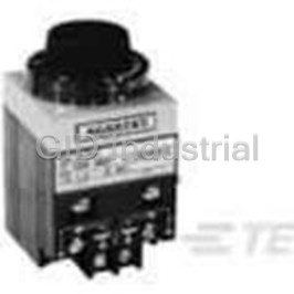
Time Delay Relay 48VDC 10A DPDT(114.8x82.6x78.5)mm Panel
1423159-8
Part Number
1423159-8
Price
Request Quote
Manufacturer
TE CONNECTIVITY
Lead Time
Request Quote
Category
Relays and I/O Modules » Time Delay Relay
Specifications
Manufacturer
TE Connectivity
Manufacturers Part #
1423159-8
Industry Aliases
7012NJ
Sub-Category
Time Delay Relays
Brand
AMP
Packaging
Package
Factory Pack Quantity
1
Datasheet
DDEController?Action=srchrtrv&DocNm=5-1773450-5_sec12_7000&DocType=CS&DocLang=EN.pdf
969 KiB

Extracted Text
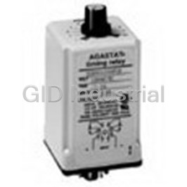
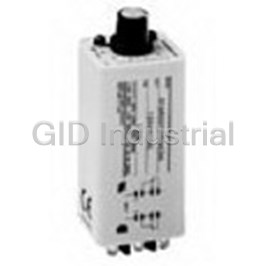
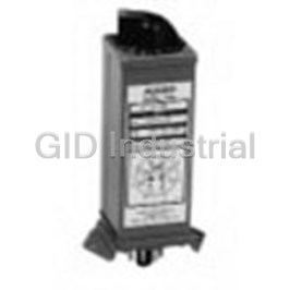
Specialty Relays AGASTAT 7000 Series, Industrial Electropneumatic Timing Relay Design & Construction On-delay model 7012 (delay on pickup) There are three main components of Applying voltage to the coil (L1-L2) for Series 7000 Timing Relays: at least 50 msec starts a time delay Timing Head cir cu lates air through a lasting for the preset time. During this vari able length to provide linearly pe ri od the nor mal ly closed con tacts adjustable timing. Pat ent ed design pro- (3-5 and 4-6) re main closed. At the end vides easy ad just ment and long service of the delay period the norm al ly closed life under severe operating con di tions. contacts break and the normally open Precision-Wound Potted Coil contacts (1-5 and 2-6) make. The Total sealing without external leads con tacts re main in this trans ferred eliminates moisture prob lems, gives po si tion until the coil is deenergized, maximum insulation value. at which time the switch ret urns to its Snap-Action Switch Assembly — orig i nal position. custom-de signed over-center mecha- De-energizing the coil, either dur ing or Product Facts nism provides snap action. Standard after the de lay pe ri od, will re cy cle the switches are DPDT arrangement. unit within 50 msec. n Available in on-delay, true Each of these subassemblies forms off-delay, and on/off-delay It will then pro vide a full delay period self-con tained mod ules assembled at upon re-energization, re gard less of how n Timing from 0.1 seconds to the factory with the other two to afford often the coil voltage is in ter rupt ed a wide choice of operating types, coil 60 minutes, in linear before the unit has been per mit ted to voltages, and timing ranges. increments "time-out" to its full delay setting. The squared design with front terminals n Oversize adjustment knobs, and rear mounting permits the grouping of serrated with high-resolution Series 7000 units side-by-side in mini- markings visible from all mum panel space. Auxiliary switch es may Off-delay model 7022 (delay on dropout) angles makes the timer be add ed in the base of the unit, without easy to set timers affecting the overall width or depth. Applying voltage to the coil (for at least 50 msec) will transfer the switch, n Inherent transient immunity Operation breaking the nor mal ly closed contacts Two basic operating types are available. n Standard voltages from (1-5 and 2-6), and mak ing the nor mal ly “On-De lay” mod els provide a delay period 6-550VAC and 12-550VDC open contacts (3-5 and 4-6). Contacts on energization, at the end of which the (special voltages available) remain in this transferred position as long switch transfers the load from one set of as the coil is en er gized. The time delay n Available in 2-pole or 4-pole contacts to an oth er. De-energizing the be gins immediately upon de-energization. models unit dur ing the delay period im me di ate ly At the end of the de lay period the switch recycles the unit, ready ing it for another n Numerous enclosure returns to its normal po si tion. full de lay period on re-energization. options — explosion proof, Re-energizing the coil during the delay In "Off-Delay" models the switch trans- dust tight, watertight, period will im me di ate ly return the timing fers the load im me di ate ly upon energiza- hermetically-sealed, mechanism to a point where it will pro- tion and the delay period does not be gin vide a full delay period upon sub se quent NEMA 1 until the unit is de-energized. At the end de-energization. The switch remains in of the delay period the switch returns to n Auxiliary timed and the transferred position. its original po si tion. Re- en er giz ing the instantaneous switches can unit during the delay period im me di ate ly be added for greater resets the timing, ready ing it for another switching flexibility full delay period on de-energization. No power is required during the timing n Many mounting options — period, providing a true off delay. Surface mount, Panel In addition to these basic operating types, mount, Octal plug-in “Double-Head” models offer sequential mounting delays on pull-in and drop-out in one n Options: quick-connect unit. With the addition of auxiliary terminals, dial stops, and switches the basic models provide two- step timing. transient pro tec tion module Note: Seismic & radiation tested n Easy-to-reach screw E7000 models are available. terminals, all on the face of Consult factory for detailed the unit, clearly identified in for ma tion. n Modular assembly — timing head, coil as sem bly and switchblock are all individual modules, with switches field-replaceable Note: 7032 types and certain models with accessories are not agency approved. n File E15631, Users should thoroughly review the technical data before selecting a product part File LR29186 number. It is recommended that users also seek out the pertinent approvals files of the agencies/laboratories and review them to ensure the product meets the requirements R for a given application. R Consult factory for ordering information. 12–8 Catalog 5-1773450-5 Dimensions are shown for Dimensions are in millimeters USA: +1 800 522 6752 For additional support numbers Revised 3-13 reference purposes only. unless otherwise specified. Asia Pacific: +86 0 400 820 6015 please visit www.te.com Specifications subject UK: +44 800 267 666 www.te.com to change. Specialty Relays Specialty Relays AGASTAT 7000 Series, Industrial Electropneumatic Timing Relay (Continued) 4. De-energizing coil resets both 4. Main switch transfers after total Auxiliary Switch Options for Auxiliary Switch Options switches instantly. First delay is preset delay. First delay is independ- On-Delay To increase the versatility of the basic independently adjustable, up to 30% ently adjustable, up to 30% of over all timer mod els, aux il ia ry switches may be Instant Transfer (Auxiliary Switch of over all delay. (Rec om mend ed delay. (Rec om mend ed maximum added to either on-delay or off-delay Code L, max i mum of 2 per relay.) maximum 100 sec onds.) 100 sec onds.) types. They switch additional circuits, 1. Energizing coil begins time delay and Instant Transfer (Auxiliary Switch pro vide two-step timing action, or fur- Auxiliary Switch Options for transfers aux il ia ry switch. Code L, max i mum of 1 per relay.) nish electrical in ter lock for sus tained Off-Delay 2. Main switch transfers after total coil energization from a momentary 1. Energizing coil transfers main and preset delay. In these models the same auxiliary impulse, depending on the type selected auxiliary switch es in stant ly. switch provides ei ther two-step timing or 3. De-energizing coil resets both and its ad just ment. They are installed at 2. De-energizing coil resets auxiliary instant transfer action, de pend ing on the switches instantly. the factory. All aux il ia ry switches are switch and be gins time delay. ad just ment of the actuator. Auxiliary switch is nonadjustable. SPDT with UL listings of 10A @ 125, 3. Main switch transfers after total Two-Step Timing (Auxiliary Switch 250, or 480 VAC. A maximum of one Two-Step Timing (Auxiliary Switch preset delay. Code T, max i mum of 1 per relay.) Code T or two Code L auxiliary switch es Code T, max i mum of 1 per relay.) Auxiliary switch is factory adjusted to 1. Energizing coil transfers main and may be added to each relay. The L or LL 1. Energizing coil begins time delay. give instant trans fer op er a tion. Two-step auxiliary switch es in stant ly. switch is available with on-delay relays 2. After first delay auxiliary switch timing may be set at the factory to cus- only. The T switch is available with both 2. De-energizing coil begins time delay. transfers. tomer specification up to a 3:2 ratio. the on-delay and off-de lay relays. 3. After first delay auxiliary switch 3. Main switch transfers after total transfers. preset delay. On-delay, Off-delay Model 7032 (Double Head) The Double Head model provides delayed switch trans fer on energization of its coil, and de layed resetting upon coil de- energization. Each delay period is in de pen dent ly adjustable. In new circuit designs or the improvement of ex ist ing con trols now using two or more conventional tim ers, the Double Head unit offers distinct advantages. Its compact design saves panel space, while the simplified wiring reduces costly in ter con nec tion. 12 On-delay Model 7014, Off-delay Model 7024 With the addition of an extra switch block at the bot tom of the basic unit, this version of the Series 7000 offers four pole switch capacity with simul taneous tim ing or two-step timing. The two-step operation is achieved by factory adjustment to your specifications. For two-step operation, a maximum timing ratio be tween upper and lower switches of 3:2 is rec om mend ed. Once ad- just ed at the factory, this ratio remains con stant regardless of changes in dial settings. (Ex: If up per switch transfer is set on dial at 60 sec., minimum time on lower switch should be 40 sec.) This Series 7000 unit offers many of the per for m ance fea- tures found in basic models — voltage ranges, timing and switch capacities. Four pole models add approximately 1-1/4" to the max i- mum height of the basic model, approximately 1/8" to the depth. They are designed for vertical op er a tion only. 12–9 Catalog 5-1773450-5 Dimensions are shown for Dimensions are in millimeters USA: +1 800 522 6752 For additional support numbers Revised 3-13 reference purposes only. unless otherwise specified. Asia Pacific: +86 0 400 820 6015 please visit www.te.com Specifications subject UK: +44 800 267 666 www.te.com to change. Specialty Relays AGASTAT 7000 Series, Industrial Electropneumatic Timing Relay (Continued) Surge/Transient Protection Option The Surge/Transient Protection Option pro tects elec tron ic Product Facts con trol cir cuits from tran sients and surg es which are n Protect electronic control gen er at ed when the timer coil is ac ti vat ed. The de vice is not circuits from voltage po lar i ty sen si tive and permits the user to ini tiate, delay, transients generated by the sequence and pro gram equip ment ac tions over a wide range timer coil of ap pli ca tions under the most se vere operating con di tions. The varistor will not affect the operating characteristics of n Fast response to the rapidly the 7000 Tim er. The varistor has bilateral and symmetrical rising back E.M.F. voltage and current characteristics. n High performance clamping voltage char ac ter is tics n UL recognized, (except varistor and coil together). Transient Suppressor Option "V" n Timer NOT polarity sensitive Timing Specifications (All values shown are at nominal voltage and 25°C unless otherwise specified) Operating Modes — Operating Voltage Coil Data (for DPDT) Model 7012/7014 — On-delay (delay on pick-up). Operating* Operating Model 7022/7024 — Off-delay (delay on drop-out). Coil Code Rated Voltage Rated Voltage Part # Letter Voltage Range Volt age Range Model 7032 — On-delay, off-delay (double head). @ 60Hz @50Hz Timing Adjustment — Timing is set by simply turning the dial to the desired time 7000 A 120 102-132 110 93.5-121 value. In the zone of approximately 25° sep a rat ing the high and low end of timing B 240 204-264 220 187-242 ranges A,D,E, and K, in stan ta neous operation (no time delay) will occur. All other C 480 408-528 ranges produce an infinite time de lay when the dial is set in this zone. D 550 468-605 Models 7014 and 7032 are available with letter dials only. The upper end of the time E 24 20.5-26.5 ranges in these models may be twice the values shown. AC F 127 108-140 Linear Timing Ranges — G 240 204-264 Models 7012, Models 7014, Code H 12 10.2-13.2 7022, 7024 7032 I6 5.1-6.6 A .1 to 1 Sec. .2 to 2 Sec. J 208 178-229 B .5 to 5 Sec. .7 to 7 Sec. Dual Voltage Coil C 1.5 to 15 Sec 2 to 20 Sec. K (Combines A&B) D 5 to 50 Sec. 10 to 100 Sec. Special AC Coils E 20 to 200 Sec. 30 to 300 Sec. L (L1, L2, etc.) F 1 to 10 Min. 1.5 to 15 Min. 7010 M 28 22.4-30.8 H 3 to 30 Min. 3 to 30 Min. N 48 38.4-52.8 I 6 to 60 Min. Not Avail. O 24 19.2-26.4 J 3 to 120 Cyc. Not Avail. P 125 100-137.5 K 1 to 300 Sec. Not Avail. Q 12 9.6-13.2 R 60 48-66 Repeat Accuracy — DC S 250 200-275 For delays of 200 seconds or less: 7012*, 7022, 7024: ±5% T 550 440-605 7014*: ±10% U 16 12.8-17.6 7032: ±15% V 32 25.8-35.2 For delays greater than 200 seconds: 7012*, 7022, 7014*, 7024: ±10% W 96 76.8-105.6 7032: ±15% Y6 4.8-6.6 * The first time delay afforded by Model 7012 with H (3 to 30 min.) and I (6 to 60 Z 220 176-242 min.) time ranges or Model 7014 with H time range will be approx. 15% long er than Special DC Coils sub se quent delays due to coil temperature rise. X (X1, X2, etc.) Reset Time — 50 msec. (except model 7032) *Four pole Models: Operational voltage range 90% to 110% for AC units; 85% to Relay Release Time — 50 msec. for on-delay models (7012/7014) 110% for DC units. Relay Operate Time — 50 msec. for off-delay models (7022/7024) See next page for more coil data. 12–10 Catalog 5-1773450-5 Dimensions are shown for Dimensions are in millimeters USA: +1 800 522 6752 For additional support numbers Revised 3-13 reference purposes only. unless otherwise specified. Asia Pacific: +86 0 400 820 6015 please visit www.te.com Specifications subject UK: +44 800 267 666 www.te.com to change. Specialty Relays Specialty Relays AGASTAT 7000 Series, Industrial Electropneumatic Timing Relay (Continued) Timing Specifications (All values shown are at nominal voltage and 25°C unless otherwise specified) Minimum operating voltages are based on ver ti cal ly mount ed 7012 units. 7012 hor i- Dielectric — Withstands 1500 volts RMS 60Hz between terminals and ground. zon tal ly mounted or 7022 ver ti cal ly or horizontally mounted units will operate sat is- 1,000 volts RMS 60 Hz between non-con nect ed terminals. For dielectric specification fac to ri ly at minimum voltages approximately 5% low er than those list ed. on hermetically sealed mod els consult factory. AC units drop out at approximately 50% of rated voltage. DC units drop out at ap prox- Insulation Resistance — 500 Megohms with 500VDC applied. i mate ly 10% of rated voltage. Temperature Range — All units may be operated on intermittent duty cy cles at voltages 10% above the listed Operating — -20°F to +165°F (-29°C to 74°C) maximums (in ter mit tent duty - maximum 50% duty cycle and 30 minutes “on” time.) Storage — -67°F to +165°F (-55°C to 74°C) Surge/Transient Protection Option Characteristics (DC Timers Only) Temperature Variation — Using a fixed time delay which was set and measured when the ambient temperature was 77°F (25°C), the maximum observed shift in the Coil Voltage Max Excess Max De-energization Nominal (DC) Energy Capacity (Joule) Tran sient Voltage average of three con sec u tive time de lays was -20% at -20°F (-29°C) and +20% at 165°F (74°C). 12 V 0.4 J 48 V 24 V 1.8 J 93 V Mounting/Terminals — Normal mounting of the basic unit is in a vertical po si tion, from the back of the panel. All units are tested for vertical operation. Basic 28 V 1.8 J 93 V models (7012, 7022) may also be horizontally mount ed, and will be adjusted ac cord- 32 V 2.5 J 135 V ing ly when Accessory Y1 is spec i fied in your order. 48 V 3.57 J 145 V Standard screw terminals (8-32 truss head screws sup plied) are located on the front of 60 V 6 J 250 V the unit, with per ma nent sche mat ic markings. Barrier isolation is de signed to ac com- 96 V 10 J 340 V mo date spade or ring tongue ter mi nals, with spacing to meet all industrial control 110 V 10 J 340 V spec i fi ca tions. 125 V 10 J 340 V The basic Series 7000 may also be panel mounted with the addition of a panel mount 220 V 17 J 366 V kit, X option, that includes all nec es sary hardware and faceplate. This offers the 250 V 17 J 366 V con ve nience of “out-front” adjustment, with large dial skirt knob. The faceplate and Surge Life — knob blend with ad vanced equipment and console designs, while the body of the unit Applied 100,000 times continuously with the in ter val of 10 seconds at room tempera- and its wiring are protected behind the panel. ture. Below 68 VAC: 12A; Above 68 VAC: 35A Other mounting options include plug-in styles and special configurations to meet Temperature Range — unusual installation re quire ments. Contact factory for details. Operating — -22°F to +167°F (-30°C to + 75°C) Power Consumption — Approximately 8 watts power at rated voltage . Storage — -40°F to +167°F (-40°C to +75°C) Approximate Weights — Output/Life Contact Ratings — Contact Capacity in Amps (Resistive Load) Models 7012, 7022 . . . . . . . . . . . . . . . . . . . . . . . 2 lbs. 4 ozs. Contact Min. 100,000 Min. 1,000,000 7014, 7024 . . . . . . . . . . . . . . . . . . . . . . 2 lbs. 10 ozs. Voltage Operations Operations 7032 . . . . . . . . . . . . . . . . . . . . . . . . . . . . 3 lbs. 5 ozs. 12 30 VDC 15.0 7.0 Weight may vary slightly with coil voltage. 110 VDC 1.0 0.5 120 V 60Hz 20.0 15.0 240 V 60Hz 20.0 15.0 480 V 60Hz 12.0 10.0 10 Amps Resistive, 240 VAC 1/4 Horsepower, 120 VAC/240VAC (per pole) 15 Amps 30 VDC (per pole) 5 Amps, General Purpose, 600VAC (per pole) 12–11 Catalog 5-1773450-5 Dimensions are shown for Dimensions are in millimeters USA: +1 800 522 6752 For additional support numbers Revised 3-13 reference purposes only. unless otherwise specified. Asia Pacific: +86 0 400 820 6015 please visit www.te.com Specifications subject UK: +44 800 267 666 www.te.com to change. Specialty Relays AGASTAT 7000 Series, Industrial Electropneumatic Timing Relay (Continued) Outline Dimensions (Dimensions in inches) Models 7012, 7022 Models 7014, 7024 Model 7032 Panel Mount Option “X” Surge/Transient Protection Option 12–12 Catalog 5-1773450-5 Dimensions are shown for Dimensions are in millimeters USA: +1 800 522 6752 For additional support numbers Revised 3-13 reference purposes only. unless otherwise specified. Asia Pacific: +86 0 400 820 6015 please visit www.te.com Specifications subject UK: +44 800 267 666 www.te.com to change. Specialty Relays Specialty Relays AGASTAT 7000 Series, Industrial Electropneumatic Timing Relay (Continued) Ordering Information Typical Part No. ‰ 70 12 A D GZ 1. Basic Series: 70 = 7000 series electropneumatic timing relay 2. Operation: 1 = On-delay 3 = On-delay, off-delay (double head) 2 = Off-delay 3. Contact Arrangement: 2 = 2PDT (2 form C) **4 = 4PDT (4 form C) 4. Coil Voltage: AC Coils DC Coils A = 120VAC, 60 Hz.; 110VAC, 50Hz. M = 28VDC B = 240VAC, 60 Hz.; 220VAC, 50Hz. N = 48VDC C = 480VAC, 60 Hz. O = 24VDC D = 550VAC, 60 Hz. P = 125VDC E = 24VAC, 60 Hz. Q = 12VDC F = 127VAC, 50 Hz. R = 60VDC G = 240VAC, 50Hz. S = 250VDC H = 12VAC, 60 Hz. T = 550VDC K = Dual voltage (combines A & B) U = 16VDC L = Special AC coils (L1, L2, etc.) V = 32VDC W = 96VDC Y = 6VDC Z = 220VDC X = Special DC coils (X1, X2, etc.) 5. Timing Range: Models 7012, 7022 & 7024 †Models 7014 & 7032 A = .1 to 1 sec. For model 7032 specify separate time B = .5 to 5 sec. range code for each head. Example: AB. C = 1.5 to 15 sec. Any two ranges may be selected. D = 5 to 50 sec. A = .2 to 2 sec. E = 20 to 200 sec. B = .7 to 7 sec. F = 1 to 10 min. C = 2 to 20 sec. H = 3 to 30 min. D = 10 to 100 sec. I = 6 to 60 min. E = 30 to 300 sec. 12 J = 3 to 120 cyc. F = 1.5 to 15 min. K = 1 to 300 sec. H = 3 to 30 min. 6. Options: A1 = Single quick-connect terminals (note 4). l2 = Tamper-proof Cap, transparent (Cannot be combined with Option X). A2 = Double quick-connect terminals (note 4). L = Auxiliary Switch, instant transfer. 7012 only (notes 2 & 6). B = Plug-in connectors (note 4). LL = Two Aux. Switches, instant transfer. On Model 7014 Factory Installed Only. (notes 2 & 6) GZ = Enclosure with bottom knockouts (note 1). M = Dust-tight Gasketing (notes 4 & 5). H2 = Hermetically sealed enclosure, 8 pin solder (notes 1 & 4). P = Octal Plug Adapter. Can be combined only with options l1,l2. M, S, X, or Y1. (note 4). H3 = Hermetically sealed enclosure, 8 pin octal (notes 1 & 4). S = Dial Stops. H4 = Hermetically sealed enclosure, 8 screw terminal block (notes 1 & 4). T = Auxiliary Switch, two-step timing (notes 2 & 6). *H6 = Hermetically sealed enclosure, 11 pin solder (notes 1 & 4). V = Transient/Surge Protection (for DC coil voltage only). *H7 = Hermetically sealed enclosure, 11 pin octal (notes 1 & 4). X = Panelmount includes hardware and adjustment for horizontal operation (note 4) *H8 = Hermetically sealed enclosure, 11 screw terminal block (notes 1 & 4). Y1 = Horizontal testing, for horizontal operation without panel mounting (note 4). l1 = Tamper-proof Cap, opaque black (Cannot be combined with Option X). Y2 = Horizontal testing, with Compensating Spring for vertical operation (note 4). Notes: 1. Cannot be combined with B, P or X Options 2. Cannot be combined with B, P or Y2 Options 3. Cannot be combined with GZ, H, l1, l2, K, W or Y1 Options 4. Not Avail. on 4-Pole Models 5. Not Available with L, T or LL options. 6. Not Available on hermetically sealed units. * Sized to accommodate one L or T Auxiliary Switch ** Not available on 7032 model. † Available with letter graduated dials only. Upper end of time range may be twice the value shown †† 120 cycles = 2 sec. Our authorized distributors are more likely to maintain the following items in stock for immediate delivery. 7012AA 7012AE 7012ACL 7012PB 7012PJ 7022AA 7022AE 7022AJ 7022PA 7012AB 7012AF 7012BC 7012PC 7012PK 7022AB 7022AF 7022AKT 7022PB 7012AC 7012AH 7012NC 7012PD 7012PKX 7022AC 7022AH 7022BC 7022PC 7012AD 7012AK 7012PA 7012PF 7012PJX 7022AD 7022AI 7022BK 7022PK 12–13 Catalog 5-1773450-5 Dimensions are shown for Dimensions are in millimeters USA: +1 800 522 6752 For additional support numbers Revised 3-13 reference purposes only. unless otherwise specified. Asia Pacific: +86 0 400 820 6015 please visit www.te.com Specifications subject UK: +44 800 267 666 www.te.com to change. Specialty Relays AGASTAT 7000 Series, Industrial Electropneumatic Timing Relay (Continued) Ordering Options — Can only be ordered as factory installed options (Dimensions, where shown, are in inches) A1 – Single Quick-Connect A2 – Double Quick-Connect B – Plug-In Connectors GZ – Metal En clo sure Ter mi nals Ter mi nals Use with Accessory “C” or “D” below. With knockouts for bottom connection. 3.16" W x 3.84" D x 7.63"H H – Hermetically Sealed I – Tamper-Proof Cover L – Auxiliary Switch LL – Auxiliary Switch Enclosure M – Dust tight P – Octal Plug Adapter S – Dial Stops T – Auxiliary Switch Gasket Gasket V – Transient/Surge Protection X – Panelmount Kit Mounting hardware included. Transient Protection Accessories (Not available for 7032 models) Plug-In Receptacle (Accessory C) Plug-In Receptacle (Accessory D) Screw Terminals Quick Connect Terminals Catalog No. 700137. Catalog No. 700141. For use with “B” Option. For use with “B” Option. Ordering options can only be ordered as factory installed options. 12–14 Catalog 5-1773450-5 Dimensions are shown for Dimensions are in millimeters USA: +1 800 522 6752 For additional support numbers Revised 3-13 reference purposes only. unless otherwise specified. Asia Pacific: +86 0 400 820 6015 please visit www.te.com Specifications subject UK: +44 800 267 666 www.te.com to change.
Frequently asked questions
How does Electronics Finder differ from its competitors?

Is there a warranty for the 1423159-8?
Which carrier will Electronics Finder use to ship my parts?
Can I buy parts from Electronics Finder if I am outside the USA?
Which payment methods does Electronics Finder accept?
Why buy from GID?

Quality
We are industry veterans who take pride in our work

Protection
Avoid the dangers of risky trading in the gray market

Access
Our network of suppliers is ready and at your disposal

Savings
Maintain legacy systems to prevent costly downtime

Speed
Time is of the essence, and we are respectful of yours
Related Products
Time Delay Relay 125VDC 10A DPDT(114.8x82.6x78.5)mm Panel 1-1437457-3
Time Delay Relay 125VDC 120VAC 10A DPDT(50x50x83)mm Socket 1-1437467-1
Time Delay Relay 24VDC 24VAC 10A DPDT (( 50mm 50mm 83mm)) Socket 1-1437468-3
Time Delay Relay 125VDC 120VAC 10A DPDT (( 38mm 35mm 77mm)) Socket 1-1437476-7
Time Delay Relay 28VDC 10A DPDT(63.5x38.6x123.9)mm Panel 1423152-2
Time Delay Relay 125VDC 10A DPDT(63.5x38.6x123.9)mm Chassis 1423154-1
Request a Quote

The quote request has been received
Close

Facing challenges or have inquiries? Feel free to contact us!
Call Us +1-469-283-2440
What they say about us
FANTASTIC RESOURCE
One of our top priorities is maintaining our business with precision, and we are constantly looking for affiliates that can help us achieve our goal. With the aid of GID Industrial, our obsolete product management has never been more efficient. They have been a great resource to our company, and have quickly become a go-to supplier on our list!
Bucher Emhart Glass
EXCELLENT SERVICE
With our strict fundamentals and high expectations, we were surprised when we came across GID Industrial and their competitive pricing. When we approached them with our issue, they were incredibly confident in being able to provide us with a seamless solution at the best price for us. GID Industrial quickly understood our needs and provided us with excellent service, as well as fully tested product to ensure what we received would be the right fit for our company.
Fuji
HARD TO FIND A BETTER PROVIDER
Our company provides services to aid in the manufacture of technological products, such as semiconductors and flat panel displays, and often searching for distributors of obsolete product we require can waste time and money. Finding GID Industrial proved to be a great asset to our company, with cost effective solutions and superior knowledge on all of their materials, it’d be hard to find a better provider of obsolete or hard to find products.
Applied Materials
CONSISTENTLY DELIVERS QUALITY SOLUTIONS
Over the years, the equipment used in our company becomes discontinued, but they’re still of great use to us and our customers. Once these products are no longer available through the manufacturer, finding a reliable, quick supplier is a necessity, and luckily for us, GID Industrial has provided the most trustworthy, quality solutions to our obsolete component needs.
Nidec Vamco
TERRIFIC RESOURCE
This company has been a terrific help to us (I work for Trican Well Service) in sourcing the Micron Ram Memory we needed for our Siemens computers. Great service! And great pricing! I know when the product is shipping and when it will arrive, all the way through the ordering process.
Trican Well Service
GO TO SOURCE
When I can't find an obsolete part, I first call GID and they'll come up with my parts every time. Great customer service and follow up as well. Scott emails me from time to time to touch base and see if we're having trouble finding something.....which is often with our 25 yr old equipment.
ConAgra Foods