

 Manufacturers
TE CONNECTIVITY 1423174-2
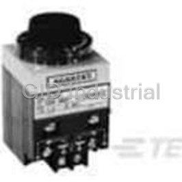
Description
Time Delay Relay 120VAC 10A 4PDT(82.55x84.33x147.83)mm Panel
1423174-2
Part Number
1423174-2
Price
Request Quote
Manufacturer
TE CONNECTIVITY
Lead Time
Request Quote
Category
Relays and I/O Modules » Time Delay Relay
Specifications
Manufacturer
TE Connectivity
Manufacturers Part #
1423174-2
Industry Aliases
E7024AC004
Sub-Category
Time Delay Relays
Brand
Raychem Wire and Tubing
Factory Pack Quantity
1
Datasheet
DDEController?Action=srchrtrv&DocNm=5-1773450-5_sec12_E7000&DocType=Catalog+Section&DocLang=English&PartCntxt=9-1437483-9.pdf
537 KiB

Extracted Text
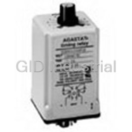
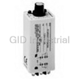
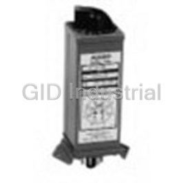
Specialty Relays Specialty Relays AGASTAT E7000 Series, Nuclear Qualified Time Delay Relays Seismic and Radiation Tested In order to satisfy the grow- Qualifying Class 1E Equip - The present E7000 Series ing need for electrical con- ment for Nuclear Power design has evolved over trol components suitable for Generating Stations) and 40 years of continual field class 1E service in nuclear IEEE Standard 344-1975 use in a wider range of power generating stations, (Seismic Qualifications for industrial applications. AGASTAT timing relays have Nuclear Power Generating On-Delay, Off-Delay and been tested for three appli- Stations). Testing was also Four-Pole versions are avail- cations. These E7000 Series referenced to ANSI/IEEE able for use with a choice electropneumatic devices C37.98 (formerly IEEE of 23 coil voltages, as well have demon strated compli- Standard 501-1978, as time delay adjustment to ance with the requirements Standard for Seismic as long as 60 minutes. of IEEE Standards 323- Testing of Relays). 1974 (Standard for Test Procedure Operate Time (milliseconds) Test Procedure Temperature Aging Hostile Environment Recycle Time (milliseconds) AGASTAT timing relay Models E7012, This test subjected the relays to a tem- Since the timing relays are intended for Time Delay (seconds) E7022, E7014 and E7024 were tested in perature of 100°C for 42 days, with per- use in auxiliary and control buildings, Repeatability (percent) accordance with the requirements of IEEE formance measured before and after and not in the reactor containment areas, Contact Bounce STD. 323-1974 (Standard for Qualifying thermal stress. a hostile environment test was per- (milliseconds at 28VDC, 1 amp) Class 1E Equipment for Nuclear Power formed in place of the Loss of Coolant Seismic Aging Contact Resistance Generating Stations), IEEE STD. 344-1975 Accident (LOCA) test. Relays were (milliohms at 28VDC, 1 amp) Sufficient interactions were performed at (Seismic Qualification for Nuclear Power subjected to combination extreme levels less than the fragility levels of the Data was measured and recorded and Generating Stations) and referenced to temperature/humidity plus under/over devices in order to satisfy the seismic used for comparison throughout the ANSI/EEE C37.98 (formerly IEEE voltage testing to prove their ability to aging requirements of IEEE STD 323- qualification test program in order to Standard 501-1978, Standard for function under adverse conditions even 1974 and IEEE STD 344-1975. detect any degradation of performance. Seismic Testing of Relays). The relays after having undergone all the previous were tested according to parameters aging simulation and seismic testing. Seismic Qualification Radiation Aging which in practice, should encompass the The devices were operated at minimum Artificially aged relays were subjected to Relays were subjected to a radiation majority of applications. Documented and maximum voltage extremes: 85 and 5 simulated seismic vibration, which veri- dosage of 2.0 x 10 Rads, which is con- data applies to timing relays which were 120 percent of rated voltage for AC fied the ability of the individual device to 12 sidered to exceed adverse plant operat- mounted on rigid test fixtures. The units, and 80 and 120 percent of rated perform its required function before, dur- ing requirements for such areas as following descriptions of the tests voltage for DC units, with temperatures ing and/or following design basis earth- auxiliary and control buildings. performed are presented in their actual ranging from 40°F to 172°F at 95 per- quakes. Relays were tested in the sequence. cent relative humidity. Cycling with Load Aging non-operating, operating and transi- The radiated units were then subjected to Baseline Performance tional modes. 27,500 operations at accelerated rate, In addition to aging tests, a series of with one set of contacts loaded to baseline tests were conducted before, 120VAC, 60Hz at 10 amps; or 125VDC and immediately after each aging at 1 amp, and the number of mechanical sequence: operations exceeding those experienced Pull-in Voltage in actual service. Drop-out Voltage Dielectric Strength at 1650V 60Hz Insulation Resistance The SRS shape (at 5 percent damping), is defined by four points: point A = 1.0 Hz and an acceleration equal to 25 percent of the Zero Period Acceleration point D = 4.0 Hz and 250 percent of the ZPA point E = 16.0 Hz and 250 percent of the ZPA point G = 33.0 Hz and a level equal to the ZPA SPECIMEN 1 & 3 (E7012 SERIES) RELAY STATE: TRANSITIONAL MODE (TD X 2) AXIS (H + V): TEST RUN NO. 41, 45, 60, 63 COMPOSITE OF FB/V-, SS/V-, SS/V+, FB/V+ X .707 DUE TO 45° INCLINATION OF TEST MACHINE. Figure 1. Response Spectrum, Transitional Mode 12–15 Catalog 5-1773450-5 Dimensions are shown for Dimensions are in millimeters USA: +1 800 522 6752 For additional support numbers Revised 3-13 reference purposes only. unless otherwise specified. Asia Pacific: +86 0 400 820 6015 please visit www.te.com Specifications subject UK: +44 800 267 666 www.te.com to change. Specialty Relays AGASTAT E7000 Series, Nuclear Qualified Time Delay Relays (Continued) Operation Two basic operating types are available: In off-delay models the switch transfers On-delay models provide a delay period the load immediately upon energization, on energization, at the end of which the and the delay period does not begin until switch transfers the load from one set of the unit is deenergized. At the end of the contacts to another. Deenergizing the delay period the switch returns to its unit during the delay period immediately original position. Reenergizing the unit recycles the unit, readying it for another during the delay period immediately full delay period on reenergization. resets the timing, readying it for another full delay period on deenergization. No power is required during the timing period. On-Delay Models, E7012 Off-Delay Models, E7022 (Delay on pick-up) (Delay on drop-out) Applying for at least 50 msec voltage Applying voltage to the coil (for at to the coil (L1-L2) starts a time delay least .050 second) will instantaneously lasting for the preset time. During this transfer the switch, breaking the normally period the normally closed contacts closed contacts (1–5 and 2–6), and (3–5 and 4–6) remain closed. At the end making the normally open contacts of the delay period the normally closed (3–5 and 4–6). Contacts remain in this contacts break and the normally open transferred position as long as the coil is contacts (1–5 and 2–6) make. The con- energized. The time delay begins imme- tacts remain in this transferred position diately upon deenergization. At the end until the coil is deenergized, at which of the delay period the switch returns to time the switch instantaneously returns its normal position. to its original position. Reenergizing the coil during the delay Deenergizing the coil, either during or period will immediately return the timing after the delay period, will recycle the mechanism to a point where it will pro- unit within .050 second. It will then vide a full delay period upon subsequent provide a full delay period upon reener- deenergization. The switch remains in gization, regardless of how often the coil the transferred position. voltage is interrupted before the unit has Four Pole Models, E7014, been permitted to “time-out” to its full E7024 delay setting. With the addition of an extra switch block at the bottom of the basic units, this version of the E7000 Series offers four pole switch capacity with simultaneous timing or two-step timing. The two-step operation is achieved by factory adjust- ment to your specifications. 12–16 Catalog 5-1773450-5 Dimensions are shown for Dimensions are in millimeters USA: +1 800 522 6752 For additional support numbers Revised 3-13 reference purposes only. unless otherwise specified. Asia Pacific: +86 0 400 820 6015 please visit www.te.com Specifications subject UK: +44 800 267 666 www.te.com to change. Specialty Relays Specialty Relays AGASTAT E7000 Series, Nuclear Qualified Time Delay Relays (Continued) Time Delay Information Delay Setting Contact Ratings — Nuclear All units are furnished with dials in Dial graduations are provided to minimize Resistive at 125 VDC . . . . . . . . 1.0 Amp linear increments covering the range the time required to set the unit to a Resistive at 120 VAC 60 Hz. . . 10.0 Amp selected. (See “Catalog Number Code”). specific delay. Rotate the dial clockwise Contact Ratings — Non-Nuclear In addition, ranges B through K provide to increase the delay; counter-clockwise Contact Capacity in Amps non-linear adjustment from .2 second to to decrease it. (Resistive Loads) the beginning of the linear zone. The following procedure is recom- Contact Min. 100,000 mended if the unit must be set to a very Repeat Accuracy Voltage Operations precise delay value: Repeat accuracy at any fixed temperature 30VDC 15.0 1. Set dial to desired time delay. (On is defined as: 110VDC 1.0 letter-graduated units, this requires *The repeat accuracy deviation (A ) of R 120V 60Hz 20.0 an approximation of a percentage a time-delay relay is a measure of the 240V 60 Hz 20.0 value between the arrowhead “” maximum deviation in the time-delay on the dial, which provides minimum 480V 60 Hz 12.0 that will be experienced in successive time, and the letter “E,” which Four pole models add approximately operations at any particular time setting provides maximum time.) 1-1/4" to the maximum height of the of the relay and for any particular 2. Record as many time delays as basic model, approximately 1/8" to the operating voltage or current. required to establish a stable average. depth. They are designed for vertical Repeat accuracy is obtained from the 3. If the recorded average delay is operation only. following formula: shorter than the desired time, turn (T –T ) Timing Adjustment 1 2 dial slightly clockwise; if it is longer, A = ± 100 R (T + T ) 1 2 The AGASTAT E7000 Series is the first turn dial counter-clockwise. Where — electropneumatic timer to offer the ease 4. Repeat step 2 after each adjustment, T = Maximum time delay. of adjustment and resetting of a graduated 1 until required delay is recorded. T = Minimum time delay. dial head. Discrete ranges covering a 2 Because of the variety of environments total span from .1 second to 60 minutes *NEMA part ICS 2-218.02 in which time delay relays are applied, are available. (See table on page 12-20.) Repeat accuracy at any fixed temperature we recommend a re-check of the time Each has its own graduated, clearly is ± 10% of setting. delay after approximately three hours of identified dial. Timing is set by simply The first time delay afforded by units operation. If any change from the initial turning the dial to the desired time value. with H (3 to 30 minutes) and I (6 to 60 time setting is apparent, the relay should In the zone of approximately 25° sepa- minutes) time ranges may be up to 15% be reset to the desired delay. The time rating the high and low ends of timing longer than subsequent delays, due to delay accuracy should then be moni- ranges A, D, E, and K, instantaneous coil temperature rise. tored on a monthly basis for several operation (no time delay) will occur. All months, and if no substantial change in Dial position error is not included in the other ranges produce an infinite time 12 time delay has taken place, the frequency repeat accuracy specification above. delay when the dial is set in this zone. of checking may be reduced. It is recommended that this procedure be incorporated in the Operating Instructions for your equipment. 12–17 Catalog 5-1773450-5 Dimensions are shown for Dimensions are in millimeters USA: +1 800 522 6752 For additional support numbers Revised 3-13 reference purposes only. unless otherwise specified. Asia Pacific: +86 0 400 820 6015 please visit www.te.com Specifications subject UK: +44 800 267 666 www.te.com to change. Specialty Relays AGASTAT E7000 Series, Nuclear Qualified Time Delay Relays (Continued) Relay Release (Recycle) Time — Environmental Characteristics Operating Conditions Model E7012 — 50 ms max. with DC or (Qualified Life) Parameter (Normal Environment) AC coils Temperature — Coil Operating Voltage, Nominal Model E7022 — N/A Minimum — 40°F (Rated) — Contact Ratings, Continuous — Normal — 70°F - 104°F Pull-in (% of rated value) — (Resistive at 125 Vdc) — Maximum — 156°F 80% min. with DC; 85% min. with 1.0 amp with DC or AC coils AC coils Humidity (R.H. %) — (Resistive at 120 Vac, 60 Hz) — Drop-out (% of rated value) — Minimum — 10% 10.0 amp with DC or AC coils 10% approx. with DC coils; Normal — 40-60% 50% approx. with AC coils Insulation Resistance Maximum — 95% Power (Watts at rated value) — (In megohms at 500 Vdc) — Pressure — Atmospheric 8 approx. with DC or AC coils 500 min. with DC or AC coils Radiation (rads) — Relay Operate Time — Dielectric (Vrms, 60 Hz) — 5 2.0 X 10 Gamma max. Model E7012 — N/A Between Terminals and Ground — Model E7022 — 50 ms. max. with DC 1,500 with DC or AC coils or AC coils Between Non-connected Terminals — 1,000 with DC or AC coils Repeat Accuracy — ±10% with DC or AC coils Operating Conditions (Abnormal Environment) Adverse Operating Normal DBE “A” DBE “B” DBE “C” DBE “D” Specifications Temperature (°F) 70-104 40 120 145 156 Humidity (R.H. %) 40-60 10-95 10-95 10-95 10-95 Coil Operating Voltage * (% of Rated) Model E7012 (AC) 85-110 85-110 85-110 85-110 85-110 (DC) 80-110 80-110 80-110 90-110 90-110 Model E7022 (AC) 85-110 85-110 85-110 85-110 85-110 (DC) 80-110 80-110 80-110 80-110 80-110 *All coils may be operated on intermittent duty cycles at voltages 10% above listed maximums (Intermittent Duty = Maximum 50% duty cycle and 30 minutes “ON” time.) Contact ratings as listed under Approximate Weight — The date of manufacture can be found REPLACEMENT SCHEDULE the UL Component Recognition in the first four (4) digits of the serial Model E7012 and E7022 with AC Program for 100,000 operations number on the nameplate: The qualified life of this unit is Coils — 2.13 lbs. (Per pole) — 25,000 operations or 10 years First two digits indicate XX XX Model E7012 and E7022 with DC 10 Amps, resistive, 240 VAC; the year from the date of manufacture, Coils — 2.25 lbs. 1/4 horsepower, 120 VAC/240 VAC; whichever occurs first. Second two digits indicate Model E7014 and E7024 with AC 15 Amps, 30 VDC; the week. Coils — 2.43 lbs. 5 Amps, General Purpose, 600 VAC Example: Date code 8014: 80 indicates Model E7014 and E7024 with DC Coil Data — 1980; 14 indicates the week of April 2 Coils — 2.57 lbs. All units draw approximately 8 watts through 8. (Weight may vary slightly with particular power at rated voltage. coil voltage.) The operating voltage range for AC MODEL E7012PC003 Terminals — relays is 85 to 110 percent of nominal COIL 125VDC Serial 8014 – Standard screw terminals (#8 – 32 truss rated value. TIME 1.5 TO 15 SEC. head screws supplied) are located on the AC units drop-out at approximately 50% L1 L2 front of the unit, with permanent of rated voltage. schematic markings. Barrier isolation is The operating range of DC relays is 80 designed to accommodate spade or to 110 percent of nominal rated value. ring-tongue terminals with spacing to DC units drop-out at approximately 10% meet industrial control specifications. of rated voltage. Note: TE Connectivity Corporation All units may be operated on intermittent cannot recommend the use of its duty cycles (50% on/off, maximum 30 products in the containment areas of minutes on) at voltages 10% above the Nuclear Power Generating Stations. listed maximums. 12–18 Catalog 5-1773450-5 Dimensions are shown for Dimensions are in millimeters USA: +1 800 522 6752 For additional support numbers Revised 3-13 reference purposes only. unless otherwise specified. Asia Pacific: +86 0 400 820 6015 please visit www.te.com Specifications subject UK: +44 800 267 666 www.te.com to change. Specialty Relays Specialty Relays AGASTAT E7000 Series, Nuclear Qualified Time Delay Relays (Continued) Dimensions and Mounting 12 L1 L2 M M The E7000 Series relay must A bracket for mounting the are provided in the rear of Mounting Instructions be mounted in the vertical device and the screws and the device for attaching the position. All performance lockwashers required to mounting bracket, or for specifications of these units attach it to the relay are mounting the relay directly are valid only when they are supplied with each unit. to a panel, from the rear. mounted in this manner. Four #8–32 tapped holes 12–19 Catalog 5-1773450-5 Dimensions are shown for Dimensions are in millimeters USA: +1 800 522 6752 For additional support numbers Revised 3-13 reference purposes only. unless otherwise specified. Asia Pacific: +86 0 400 820 6015 please visit www.te.com Specifications subject UK: +44 800 267 666 www.te.com to change. Specialty Relays AGASTAT E7000 Series, Nuclear Qualified Time Delay Relays (Continued) Ordering Information Catalog Number Code E 70 1 2 A A **004 Nuclear AGASTAT Operation Contact Arrangement Coil Time Range Configuration Safety 7000 Series 1 – On-delay 2 – Double Pole Voltage E7012, E7022 Code Related Timing Relay 2 – Off-delay Double Throw 4 – Four Pole Double Code Code Throw A 120V 60 Hz A .1 to 1 sec. 110V 50 Hz B .5 to 5 sec. B 240V 60Hz C 1.5 to 15 sec. 220V 50Hz D 5 to 50 sec. C 480V 60Hz E 20 to 200 sec. D 550V 60Hz F 1 to 10 min. AC E 24V 60Hz H 3 to 30 min. F 127V 50Hz I 6 to 60 min. G 240V 50Hz K 1 to 300 sec. H 12V 60Hz I 6V 60Hz *E7014 J 208V 60Hz A .2 to 2 sec. B .7 to 7 sec. M 28 VDC C 2 to 20 sec. N 48 VDC D 10 to 100 sec. O 24 VDC E 30 to 300 sec. P 125 VDC F 1.5 to 15 min. Q 12 VDC H 3 to 30 min. R 60 VDC * Model E7014 is available with letter-graduated dials only. The DC S 250 VDC E7024 upper end of the time ranges in these models may be twice the T 550 VDC A .1 to 1 sec. values shown. U 16 VDC B .5 to 5 sec. ** Configuration Code V 32 VDC C 1.5 to 15 sec. The Configuration Code is a suffix to the Model Number which W 96 VDC D 5 to 50 sec. provides a means of identification. When a significant product Y 6 VDC E 20 to 200 sec. change is introduced, the Configuration code and specification Z 220 VDC F 1 to 10 min. sheets will be revised. (001, 002, 003, 004, etc.). H 3 to 30 min. I 6 to 60 min. K 1 to 300 sec. Relay Classifications Control Code Summary Configuration Control Product Code – 001 Code – 002 Code – 003 Code – 004 E7000 Contains all materials present in Sept. 1981 — Elastomer gasket March 1989 — Paint change to Dec. 1991 — Paint change to original qualification testing. material change to improve timing head portion of relay. timing head portion of relay. thermal aging properties. New paint: Sherwin-Williams New paint: Prime coatings Material changed for Buna-N or E61YC37 primer and PPG No. 28032 Enamel. No primer Neoprene to Neoprene only. W48392 silver polyester top is used with this finish. coat. Configuration Code: The Configuration code is a suffix to the Model Number which provides a means of identification. When a significant product change is introduced, the Configuration code and specification sheets will be revised. (001, 002, 003, 004, etc.) PPG is a trademark of PPG Industries. Sherwin-Williams is a trademark of The Sherwin-Williams Company. 12–20 Catalog 5-1773450-5 Dimensions are shown for Dimensions are in millimeters USA: +1 800 522 6752 For additional support numbers Revised 3-13 reference purposes only. unless otherwise specified. Asia Pacific: +86 0 400 820 6015 please visit www.te.com Specifications subject UK: +44 800 267 666 www.te.com to change.
Frequently asked questions
How does Electronics Finder differ from its competitors?

Is there a warranty for the 1423174-2?
Which carrier will Electronics Finder use to ship my parts?
Can I buy parts from Electronics Finder if I am outside the USA?
Which payment methods does Electronics Finder accept?
Why buy from GID?

Quality
We are industry veterans who take pride in our work

Protection
Avoid the dangers of risky trading in the gray market

Access
Our network of suppliers is ready and at your disposal

Savings
Maintain legacy systems to prevent costly downtime

Speed
Time is of the essence, and we are respectful of yours
Related Products
Time Delay Relay 125VDC 10A DPDT(114.8x82.6x78.5)mm Panel 1-1437457-3
Time Delay Relay 125VDC 120VAC 10A DPDT(50x50x83)mm Socket 1-1437467-1
Time Delay Relay 24VDC 24VAC 10A DPDT (( 50mm 50mm 83mm)) Socket 1-1437468-3
Time Delay Relay 125VDC 120VAC 10A DPDT (( 38mm 35mm 77mm)) Socket 1-1437476-7
Time Delay Relay 28VDC 10A DPDT(63.5x38.6x123.9)mm Panel 1423152-2
Time Delay Relay 125VDC 10A DPDT(63.5x38.6x123.9)mm Chassis 1423154-1
Request a Quote

The quote request has been received
Close

Facing challenges or have inquiries? Feel free to contact us!
Call Us +1-469-283-2440
What they say about us
FANTASTIC RESOURCE
One of our top priorities is maintaining our business with precision, and we are constantly looking for affiliates that can help us achieve our goal. With the aid of GID Industrial, our obsolete product management has never been more efficient. They have been a great resource to our company, and have quickly become a go-to supplier on our list!
Bucher Emhart Glass
EXCELLENT SERVICE
With our strict fundamentals and high expectations, we were surprised when we came across GID Industrial and their competitive pricing. When we approached them with our issue, they were incredibly confident in being able to provide us with a seamless solution at the best price for us. GID Industrial quickly understood our needs and provided us with excellent service, as well as fully tested product to ensure what we received would be the right fit for our company.
Fuji
HARD TO FIND A BETTER PROVIDER
Our company provides services to aid in the manufacture of technological products, such as semiconductors and flat panel displays, and often searching for distributors of obsolete product we require can waste time and money. Finding GID Industrial proved to be a great asset to our company, with cost effective solutions and superior knowledge on all of their materials, it’d be hard to find a better provider of obsolete or hard to find products.
Applied Materials
CONSISTENTLY DELIVERS QUALITY SOLUTIONS
Over the years, the equipment used in our company becomes discontinued, but they’re still of great use to us and our customers. Once these products are no longer available through the manufacturer, finding a reliable, quick supplier is a necessity, and luckily for us, GID Industrial has provided the most trustworthy, quality solutions to our obsolete component needs.
Nidec Vamco
TERRIFIC RESOURCE
This company has been a terrific help to us (I work for Trican Well Service) in sourcing the Micron Ram Memory we needed for our Siemens computers. Great service! And great pricing! I know when the product is shipping and when it will arrive, all the way through the ordering process.
Trican Well Service
GO TO SOURCE
When I can't find an obsolete part, I first call GID and they'll come up with my parts every time. Great customer service and follow up as well. Scott emails me from time to time to touch base and see if we're having trouble finding something.....which is often with our 25 yr old equipment.
ConAgra Foods