

 Manufacturers
TE CONNECTIVITY 1424050-1

Description
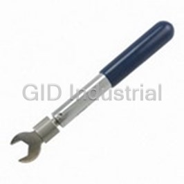
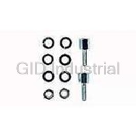
Punches & Dies PREMIUM SDE DIE BNC
1424050-1
Part Number
1424050-1
Price
Request Quote
Manufacturer
TE CONNECTIVITY
Lead Time
Request Quote
Category
Fasteners, Hardware and Fluid Transfer » Hardware Tools
Specifications
Manufacturer
TE Connectivity
Manufacturers Part #
1424050-1
Industry Aliases
1424050-1
Sub-Category
Hardware Tools
Brand
AMP
Factory Pack Quantity
1
Datasheet
DDEController?Action=showdoc&DocId=Specification+Or+Standard%7F408-8580%7FB%7Fpdf%7FEnglish%7FENG_SS_408-8580_B.pdf
257 KiB

Extracted Text
Instruction Sheet SDE Crimping Die Assemblies 91902-1, 91907-[ ], 91908-1, 408-8580 91909-1, 91910-[ ], and 1424050-1 08 NOV 16 Rev D Die Retaining Die Retaining Screw Pin (Qty: 2) Indenter Dies Ferrule Crimping Chamber Chamfered Edges Die Retaining Pin (Qty: 2) Anvil Dies Center Contact Retaining Screw Die Retaining Screw DIE ASSEMBLY PRODUCT TOOL FRAME 91902-1 50-Ohm C, HN, N, and TNC COAXICON* Connectors 354940-1 91907-[ ] ARINC Size 8 Triaxial Contacts or 9-1478240-0 91908-1 SMA Series 50-Ohm RF Connectors 91909-1 50-Ohm C, HN, N, and TNC COAXICON Connectors 9-1478240-0 91910-[ ] 50-Ohm BNC COAXICON Connectors 354940-1 or 1424050-1 50-Ohm BNC Connectors 9-1478240-0 Figure 1 1. INTRODUCTION The SDE crimping die assemblies listed in Figure 1 are designed to crimp the products also listed in Figure 1. The die assembly must be installed into the frame assembly listed in Figure 1. Refer to Instruction Sheet 408-9930 for information on the 354940-1, PRO-CRIMPER* III, frame assembly; and Instruction Sheet 408-8851 for information on the 9-1478240-0, SDE-SA, frame assembly. NOTE Dimensions in this instruction sheet are in metric units [with U.S. customary units in brackets]. Figures are not drawn to scale. Reasons for reissue of this instruction sheet are provided in Section 8, REVISION SUMMARY. 2. DESCRIPTION Each four-piece die assembly consists of two indenter dies and two anvil dies. When closed, the die assembly forms two or three crimping chambers. The larger crimping chambers crimp the ferrule of the connector onto the coaxial cable, and the smaller crimping chamber crimps the center contact onto the center conductor of the coaxial cable. Each set of dies is held in the tool frame by two pins and a screw. 3. INSTALLATION AND REMOVAL 1. Close the tool handles until the ratchet releases, then allow the tool handles to open fully. NOTE The ratchet has detents with audible "clicks" as the handles are closed. The ratchet releases on the sixth "click." 2. Remove the two die retaining screws and four die retaining pins from the tool jaws. © 2016 TE Connectivity family of companies TOOLING ASSISTANCE CENTER 1-800-722-1111 This controlled document is subject to change. 1 of 5 All Rights Reserved PRODUCT INFORMATION 1-800-522-6752 For latest revision and Regional Customer Service, *Trademark visit our website at www.te.com. TE Connectivity, TE connectivity (logo), and TE (logo) are trademarks. Other logos, product, and/or company names may be trademarks of their respective owners. ORIGINAL INSTRUCTIONS 408-8580 3. Install the anvil dies in the movable jaw of the tool frame so that the chamfered edges and marked surfaces face outward. Align the dies with the screw hole, then insert the two die retaining pins included with the die assembly through the holes in the dies and into the holes in the tool frame. 4. Secure the anvil dies with the die retaining screw included with the die assembly. DO NOT fully tighten the screw. 5. Install indenter dies in the stationary jaw of the tool frame so that the chamfered edges and marked surfaces face outward. Align the dies with the screw hole, then insert the two die retaining pins included with the die assembly through the holes in the dies and into the holes in the tool frame. 6. Secure the indenter dies with the die retaining screw included with the die assembly. DO NOT fully tighten the screw. 7. Slowly close the tool handles, making sure that the dies align properly. After the anvil dies enter the indenter dies, place a 1.57 ±0.05-mm [.062 ±.002-in.] diameter copper bus bar into the center contact crimping chamber of the die assembly. 8. Continue closing the tool handles until the ratchet has engaged sufficiently to hold the dies in place, then tighten both die retaining screws. 9. To remove the die assembly from the tool frame, close the tool handles until the ratchet releases, remove the two die retaining screws and four die retaining pins, and slide the dies out of the jaws. 4. CRIMPING PROCEDURE NOTE Refer to the instructions included with the connector for cable preparation and connector assembly. Before proceeding, ensure that the ferrule is on the cable and the braided shield is flared away from the cable. NOTE This tool frame has a crimp height adjustment feature. Initially, the crimp height should be verified. Make a sample crimp. Refer to the instructions included with the connector for the acceptable crimp height. If the crimp height is unacceptable, refer to Section 5 to adjust the crimp height. 4.1. Crimp the Center Contact (Refer To Figure 2) 1. Close the tool handles until the die assembly is partially closed. 2. Assemble the center contact onto the center conductor of the cable, and place the center contact on the anvil in the smallest crimping chamber. Make sure the flange on the end of the center contact butts against the die. 3. Holding the cable in place, close the tool handles until the ratchet releases. 4. Allow the tool handles to open fully and remove the crimped center contact from the dies. Crimping Center Contact Cross-Section View Jack Center Flange of Center Contact Flange Contact Butts Against Die Smallest Die Crimping Plug Center Chamber of Contact Flange Anvil Die Cable Die NOTE: Die shown in PRO-CRIMPER III frame assembly. Figure 2 2 of 5 Rev D 408-8580 4.2. Crimp the Ferrule (Refer To Figure 3) 1. Insert the crimped center contact into the connector body until the cable dielectric butts against the dielectric inside the connector body or until the center contact is securely positioned within the connector. Make sure that the braided shield of the cable is over the support sleeve of the connector body and that no strands from the shield enter the connector body. Crimping Ferrule Shoulder of Connector Body Butts Against Die Crimping Chamber of Anvil Die NOTE: Die shown in PRO-CRIMPER III frame assembly. Figure 3 2. Slide the ferrule over the braided shield and onto the connector until the ferrule butts against the shoulder of the connector body. 3. Place the ferrule in the appropriate crimping chamber of the anvil die so that the shoulder of the connector body butts against the edge of the die. NOTE Refer to the instructions included with the connector to determine the appropriate crimping chamber. 4. While holding the assembly together, close the tool handles until the dies have closed enough to secure the assembly in place. CAUTION Make sure that both sides of the ferrule are started evenly into the crimping chamber. DO not attempt to crimp an improperly positioned ferrule. 5. Carefully close the tool handles until the ratchet releases, then allow the tool handles to open fully, and remove the crimped connector from the dies. 5. CRIMP HEIGHT ADJUSTMENT (Refer To Figure 4) The tool frame ratchet mechanism features an adjustment wheel with numbered settings. If the crimp height is not acceptable, adjust the ratchet as follows: 1. Remove the lockscrew from the ratchet adjustment wheel. 2. Using a screwdriver, rotate the ratchet adjustment wheel from the opposite side of the tool frame. If a tighter crimp is required, rotate the ratchet adjustment wheel counterclockwise to a higher-numbered setting. If a looser crimp is required, rotate the ratchet adjustment wheel clockwise to a lower- numbered setting. Screwdriver Lockscrew Ratchet NOTE: Die shown in PRO-CRIMPER III Adjustment frame assembly shown, refer to Instruction Wheel Sheet 408-8851 for SDE-SA frame. Figure 4 3 of 5 Rev D 408-8580 3. Re-install the lockscrew. 4. Make a sample crimp and measure the crimp height. If the crimp height is still unacceptable, remove lockscrew and continue to adjust the ratchet. CAUTION Damaged product should not be used. If damage to the product is evident, it should be cut from the wire and replaced with new product. 6. MAINTENANCE AND INSPECTION The die assembly is inspected before shipment. It is recommended that the die assembly be inspected immediately upon arrival at your facility to ensure that the dies have not been damaged during shipment. The die assembly will perform correctly as long as: (1) the product specified is correct for the application, (2) the proper die assembly is used, (3) the die assembly has been measured to ensure that the openings are correct, and (4) the tool has been adjusted correctly. 6.1. Maintenance 1. Remove dust, moisture, and other contaminants with a clean, soft brush, or a clean, soft, lint-free cloth. DO NOT use any objects that could damage the dies or tool. 2. Make sure that the proper die retaining screws are properly secured. 3. When the dies are not in use, store them in a clean, dry area. 6.2. Inspection 1. Remove all lubrication and accumulated film from the dies by immersing the dies in a suitable commercial degreaser. 2. Make certain that die retaining screws and pins are properly secured. 3. Inspect the crimping surfaces for flattened, chipped, worn, or cracked areas. If damage is evident, the dies must be replaced. Refer to Section 7, REPLACEMENT. 4. Measure the die opening to ensure that it meets the dimensions given in Figure 5. 7. REPLACEMENT Order replacements through your local representative, or call 1-800-526-5142, or send a facsimile of your purchase order to 1-717-986-7605, or write to: CUSTOMER SERVICE (038-035) TYCO ELECTRONICS CORPORATION PO BOX 3608 HARRISBURG PA 17105-3608 8. REVISION SUMMARY In Figure 5, changed Crimp Height Dimension of Die Assembly 91909-1 from 1.29 to 1.19 (marked above the diamond crimp chambers) 4 of 5 Rev D 408-8580 Die Assembly Die Assembly 91902-1 91907-[ ] C A C A ±0.08 [.003] ±0.03 [.001] ±0.05 [.002] ±0.03 [.001] RG-141 TRIAXIAL CONN ARINC 8 RG-58 N PLUG B B ±0.10 [.004] ±0.05 [.002] Die Assembly Die Assembly 91908-1 91909-1 A C D E C B ±0.03 [.001] A (Typ) ±0.10 [.004] ±0.08 [.003] ±0.08 [.003] ±0.10 [.004] ±0.10 [.004] 5.69 SM A CONN 5.6 9 11 ..2 199 TWIN BNC RG 108 B A (Typ) ±0.10 [.004] Die Assembly Die Assembly 1424050-1 91910-[ ] A B D ±0.05 [.002] A (Typ) ±0.10 [.004] ±0.05 [.002] C ±0.10 [.004] INSUL CRIM P BRAID CRIM P 50 -Ohm 58 59 RG17 4-18 8 COM M BNC C ±0.05 [.002] A (Typ) B ±0.05 [.002] DIE CLOSURE DIMENSIONS (mm [in.]) DIE ASSEMBLY A B C D E 91902-1 1.93 [.076] 4.98 [.196] 5.56 [.219] --- --- 91907-[ ] 1.24 [.049] 3.78 [.149] 6.07 [.239] --- --- 91908-1 1.27 [.050] 2.44 [.096] 4.72 [.186] 5.54 [.218] 2.82 [.111] 91909-1 1.162-1.226 [.046-.048] 5.69 [.224] 7.16 [.282] --- --- 91910-2 1.219-1.283 [.048-.051] 2.34 [.092] 2.77 [.109] --- --- 91910-[ ] (Except -2) 1.219-1.283 [.048-.051] 2.90 [.114] 3.61 [.142] --- --- 1424050-1 1.12 [.044] 1.27 [.050] 2.64 [.104] 4.32 [.170] --- Figure 5 5 of 5 Rev D
Frequently asked questions
How does Electronics Finder differ from its competitors?

Is there a warranty for the 1424050-1?
Which carrier will Electronics Finder use to ship my parts?
Can I buy parts from Electronics Finder if I am outside the USA?
Which payment methods does Electronics Finder accept?
Why buy from GID?

Quality
We are industry veterans who take pride in our work

Protection
Avoid the dangers of risky trading in the gray market

Access
Our network of suppliers is ready and at your disposal

Savings
Maintain legacy systems to prevent costly downtime

Speed
Time is of the essence, and we are respectful of yours
Related Products
Crimpers TOOL 1055236-1
Mini Torque Wrenches 1055258-1

Wrenches 2098 0351 54 1055276-1
Hand Tools CABLE BENDER 1055479-1
Connector Accessories Crimp Assembly Kit 1055779-1
Crimpers TOOL 1055835-1
Request a Quote

The quote request has been received
Close

Facing challenges or have inquiries? Feel free to contact us!
Call Us +1-469-283-2440
What they say about us
FANTASTIC RESOURCE
One of our top priorities is maintaining our business with precision, and we are constantly looking for affiliates that can help us achieve our goal. With the aid of GID Industrial, our obsolete product management has never been more efficient. They have been a great resource to our company, and have quickly become a go-to supplier on our list!
Bucher Emhart Glass
EXCELLENT SERVICE
With our strict fundamentals and high expectations, we were surprised when we came across GID Industrial and their competitive pricing. When we approached them with our issue, they were incredibly confident in being able to provide us with a seamless solution at the best price for us. GID Industrial quickly understood our needs and provided us with excellent service, as well as fully tested product to ensure what we received would be the right fit for our company.
Fuji
HARD TO FIND A BETTER PROVIDER
Our company provides services to aid in the manufacture of technological products, such as semiconductors and flat panel displays, and often searching for distributors of obsolete product we require can waste time and money. Finding GID Industrial proved to be a great asset to our company, with cost effective solutions and superior knowledge on all of their materials, it’d be hard to find a better provider of obsolete or hard to find products.
Applied Materials
CONSISTENTLY DELIVERS QUALITY SOLUTIONS
Over the years, the equipment used in our company becomes discontinued, but they’re still of great use to us and our customers. Once these products are no longer available through the manufacturer, finding a reliable, quick supplier is a necessity, and luckily for us, GID Industrial has provided the most trustworthy, quality solutions to our obsolete component needs.
Nidec Vamco
TERRIFIC RESOURCE
This company has been a terrific help to us (I work for Trican Well Service) in sourcing the Micron Ram Memory we needed for our Siemens computers. Great service! And great pricing! I know when the product is shipping and when it will arrive, all the way through the ordering process.
Trican Well Service
GO TO SOURCE
When I can't find an obsolete part, I first call GID and they'll come up with my parts every time. Great customer service and follow up as well. Scott emails me from time to time to touch base and see if we're having trouble finding something.....which is often with our 25 yr old equipment.
ConAgra Foods